Review

Thin-Film Lithium Cobalt Oxide for Lithium-Ion Batteries

1
College of Materials, Xiamen University, Fujian 361005, China
2
Fujian Key Laboratory of Surface and Interface Engineering for High Performance Materials, Xiamen University, Fujian 361005, China
*
Authors to whom correspondence should be addressed.
Energies 2022, 15(23), 8980; https://doi.org/10.3390/en15238980
Submission received: 2 November 2022 / Revised: 19 November 2022 / Accepted: 21 November 2022 / Published: 28 November 2022
(This article belongs to the Special Issue Advanced and Multifunctional Materials for Energy Storage Systems)

Abstract

:
Lithium cobalt oxide (LCO) cathode has been widely applied in 3C products (computer, communication, and consumer), and LCO films are currently the most promising cathode materials for thin-film lithium batteries (TFBs) due to their high volumetric energy density and favorable durability. Most LCO thin films are fabricated by physical vapor deposition (PVD) techniques, while the influence of preparation on the materials’ properties and electrochemical performance has not been highlighted. In this review, the dominant effects (heating, substrate, power, atmosphere, etc.) on LCO thin films are summarized, and the LCO thin films fabricated by other techniques (spin coating, sol–gel, atomic layer deposition, pulsed laser deposition, etc.) are outlined. Moreover, the modification strategies including bulk doping and surface coating for powder and thin-film LCO electrodes are discussed in detail. This review may pave the way for developing novel, durable, and high-performance LCO thin films by versatile methods for TFB and other energy storage devices.

1. Introduction

1.1. Thin-Film Lithium Battery

In recent years, with the rapid development of micro-electromechanical system (MEMS) and smart wearable devices, applicable power sources with high energy density and long cycling life are urgently required [1,2]. E.g., integrated circuits, smart security cards, and other intelligent systems with the micron/nano-scale structures are in need of thin-thickness, light-weight, long-life, high-safety, and high-energy-density power supply. Therefore, the thin-film and miniaturized lithium-ion battery (LIB) has become an important research direction [3,4,5]. Among present cathode materials, lithium cobalt oxide (LCO) has a high working potential and high volumetric capacity [6,7,8,9], and its volumetric change is small enough to avoid film crack upon cycling [10,11,12]. Moreover, the LCO cathode has good conductivity, which can meet the electron transport property without conductive additives. Therefore, the research of the LCO film electrode is important for developing the high-performance thin-film lithium battery (TFB). An effective way to increase the energy density of LCO is to increase its cut-off voltage. The modification methods to elevate the cut-off voltage of powder LCO electrodes are also suitable for thin-film LCO electrodes. However, it faces several problems that hinder its wide application.

1.2. High-Voltage LiCoO2 Cathode

LCO materials have three phases: a high-temperature-phase layered structure (HT-LCO), low-temperature-phase spinel structure (LT-LCO), and rock-salt-phase structure (RS-LTO). The oxygen in the LT-LCO is arranged in an ideal cubic close-packed lattice, and Co3+ and Li+ are distributed on both sides of the oxygen layer, in which the Li+ layer contains 25% Co3+ and the Co3+ layer contains 25% Li+. The Li+ and Co3+ are randomly arranged in the lattice of LCO without a clear boundary. The HT-LCO has excellent electrochemical performance and belongs to the hexagonal R-3m space group with an α-NaFeO2 structure. The oxygen atoms are densely packed with the O3 structure along the (001) crystal plane, occupying the 6c site. The Co3+ and Li+ are alternately arranged occupying the 3b and 3a sites of oxygen octahedral holes.
Although LCO has a theoretical capacity of 274 mAh g−1, its reversible capacity is only approximately 140 mAh g−1 (4.2 V vs. Li/Li+) in practice [13,14,15,16]. Therefore, it is necessary to extract more Li+ from LCO and maintain the stability of crystal structure [17]. The stability of LCO is affected by several factors: First, when LCO undergoes the deep removal of Li+, metal-ion migration and cation segregation occur in the crystal lattice, and such structural transformations are irreversible [18,19]. Second, the release of lattice oxygen leads to the collapse of LCO framework, which leads to the distortion of the crystal structure [20,21]. Third, cathode electrolyte interphase (CEI) formation on the surface of LCO affects the Li+ diffusion and electrode durability. Some reports have noted that the cut-off voltage of LCO should not be above 4.6 V due to the phase transitions at 4.55 V to H1 and H3-3 phases, and the irreversible transformation causes the lithium loss and further capacity attenuation [22,23].
The energy density of TFB using the LCO cathode is restricted by its cut-off voltage, and the modification methods for powder LCO electrodes have important potential for thin-film LCO electrodes [24,25]. Using the surface coating, the formed artificial CEI can inhibit the interfacial side reaction and improve the stability of the LCO film under a higher cut-off voltage for delivering higher reversible capacity [26]. Bulk doping can be achieved by annealing the sputtered LCO film fabricated from a transition metal-doped LCO target under appropriate conditions [27,28]. Both bulk doping and surface coating are beneficial for the electrochemical performance and structural stability of LCO thin films upon cycling.

1.3. Fabrication of LiCoO2 Thin Films

Since the last century, magnetron sputtering deposition technology realizes the merits of high speed, low temperature, and low toxicity. The magnetron sputtering technology perfectly fits the microelectronics, micro-memory, and other micro-devices in the field of low energy demand, and has even gradually been expanded to flexible devices and implantable medical devices [29,30]. Therefore, magnetron sputtering has become the most common method for making LCO thin-film electrodes [31]. Various parameters of magnetron sputtering affect the properties of LCO film electrodes. The growth conditions of sputtered LCO have great influence on the grain orientation, microstructure, and overall stoichiometric ratio of the LCO film, and thus affect its electrochemical performance. Since LCO is an insertion-based cathode material, the powder LCO electrode is usually infiltrated by electrolyte, so that Li can be released from various directions, while the orientation of thin-film LCO material greatly affects the activation energy required for Li migration in all-solid-state batteries [32]. The orientation of LCO films is usually controlled by selecting appropriate substrate materials [33]. When LCO grains nucleate and grow on substrates with specific orientations, they will form the same orientation as the substrate [34,35,36]. Therefore, the optimal orientation conducive to Li-ion transport can be obtained by regulating the substrate [37]. The LCO films with preferred crystal orientation can be obtained by in situ heating or post-annealing at a proper temperature. By controlling the sputtering power, the LCO films with better crystallinity and favorable orientations can also be obtained [38,39,40,41]. At the same time, with the bias voltage, LCO films without post-annealing can be obtained to ensure high crystallization and phase purity [42].
Additionally, LCO thin films can also be fabricated by other techniques, including wet-chemistry [43], atomic layer deposition (ALD) [44], and pulsed laser deposition (PLD) [45]. However, each method has its pros and cons in different application contexts. Wet-chemistry is a good candidate for future mass production, while physical vapor deposition (PVD) is suitable for fabricating thin-film devices. Compared to magnetron sputtering, ALD is good at depositing conformal and ultra-thin LCO films, and PLD can be used to prepare thick LCO films with versatile composition.

1.4. Outline

In this review, the important parameters for depositing LCO thin films by magnetron sputtering are discussed, and some other methods for fabricating LCO thin-film cathodes are reported, including some important strategies for modifying the powder and thin-film LCO cathodes. From the industrial perspective, the next development is to combine the advantages and characteristics of a single strategy into multiple strategies. To obtain a higher capacity and better durability of LCO films in the limited space, the reasonable structure design of TFB could induce a higher specific energy density of the LCO thin-film cathode for more extensive application.

2. Sputtering of LiCoO2 Thin Films

According to the characteristics of target materials and the effect of target deposition, magnetron sputtering technology can be divided into radio frequency (RF) sputtering and direct current (DC) sputtering. During operation, secondary electrons are bound near the target surface by the action of a mutually perpendicular electromagnetic field, which increases the ionization rate of gas to a greater extent, thus increasing the density of incident ions. The secondary electrons fall onto the substrate after energy depletion to achieve the low heat and low damage to the substrate. The ionized inert gas molecules bombard the target material under the action of an electromagnetic field to make the materials sputtered onto the substrate, achieving the uniform deposition of films.

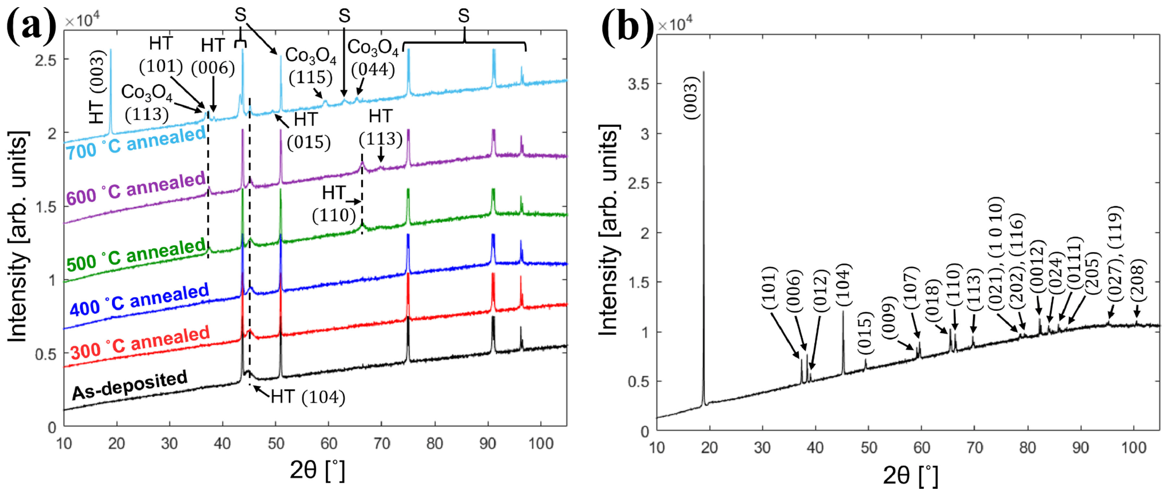
2.1. Annealing Process

In contrast to bulk LCO, most LCO films deposited by PVD technology has the problem of insufficient diffusion kinetics for nucleation and growth, which directly leads to the structural instability of LCO films. The annealing treatment of amorphous LCO films in air or oxygen can improve the crystallinity of LCO and reduce the residual stress inside the film. However, along with the increase in crystallinity, the materials are easy to peel from the substrate, and thus the control of annealing parameters is important.
Turrell et al. [46] deposited LCO films on tungsten–nickel alloy foils and annealed them at different temperatures. Figure 1a,b display the XRD patterns of film LCO and powder LCO samples, respectively. In the XRD pattern of the film annealed at 700 °C, a peak with orientation of (003) that is not favorable to lithium embedding can be found, while the peak with an orientation of (110) obtained at 500–600 °C disappears at 700 °C. The high temperature brings inevitable changes to the morphology of the substrate, and 600 °C may be the best annealing temperature in terms of structural properties in this work. The maximum capacity of 132 mAh g−1 was obtained at 0.1C with a higher cut-off voltage of 4.3 V. However, after 50 cycles, the capacity rapidly decays to 92 mAh g−1, but the cycle stability can be improved at the cost of part reversible capacity. Ma et al. [47] deposited the LCO film directly onto a stainless steel (SS) substrate by RF magnetron sputtering, and compared the influence of annealing parameters on the surface morphology of the LCO film. The annealed LCO films all show network cracks with an average width of ~100 nm. The LCO films annealed in air display more obvious crack with a width of ~400 nm. This phenomenon may be caused by the mismatch of thermal expansion coefficients between the SS substrate and the LCO thin film, leading to the residual stress and peeling from the substrate. Further optimization of the heating rate, holding time, and cooling rate of annealing may achieve the compromise between crystallinity and internal stress. The impurity diffusion from the SS substrate to LCO is also one of the reasons for the damage of the LCO structure. The sample annealed at 500 °C shows an initial discharge capacity of 32.5 μAh cm−2 μm−1, but rapidly decreases to 13.4 μAh cm−2 μm−1 after 37 cycles. This may be caused by the micro-short circuit between thin-film electrodes due to the uneven roughness of the SS substrate.

2.2. Substrate Influence

Unlike powder LCO, the thin-film LCO has the advantage of a large contact area with electrolyte, so that Li+ can be fully extracted without being mainly affected by the grain orientation. However, the contact area between the LCO film and solid electrolyte is also limited when the orientation of LCO film is vertical to the substrate.
Wu et al. [48] found that, for the (003) LCO, Li-ions needs to pass through the Co-O plane with an activation energy of up to 6.8 eV, or must pass through grain boundary with an activation energy of 0.7 eV (Figure 2a). This ion diffusion pathway is mainly limited by grain boundary contact at the (003) crystal orientation with high interfacial impedance. Another Li-ion diffusion pathway of (110) crystal orientation is parallel to the electric field, and the Li+ diffusion energy barrier along the CoO2 sheet is as low as 0.3 eV, providing fast Li+ migration channels with the lowest transfer resistance. The TFB using (110) LCO shows an excellent rate performance of ~47 μAh cm−2 μm−1 (~101 mAh g−1) at a current density of 500 μA cm−2 (10C-rates) and remains at 45 μAh cm−2 μm−1 after 100 cycles at 2C rates. Shiraki et al. [49] prepared the (10 1 ¯ 4) epitaxial LCO films with the CoO2 layer tilted at 52° relative to the surface on the Pt (110) surface. In the laminar LCO, Li-ions mainly diffuse in two dimensions along the CoO2 layer. This means that the (10 1 ¯ 4) and (11 2 ¯ 0) LCO films are suitable for Li-ion conduction. Using the platinum-coated silicon wafers, stainless steels, and titanium plates as substrates, Bohne et al. [50] observed that the different textures of LCO films are highly dependent on the substrate properties rather than the thickness of LCO films. The strong (003) preferred crystal orientation is obtained over a large range of film thickness. However, sputtering LCO films on Si wafers result in the (101) dominant crystal orientation. Yoon et al. [51] improved the electrochemical performance of TFB by adding a Li2O buffer layer to reduce the lattice matching between the LCO cathode and Al (111) current collector. This strategy inhibits the formation of an Li-deficient phase Co3O4 and retards the growth of the unmatched (003) LCO. Although the initial discharge capacity of (003) and (110) LCO cathodes are similar (42.4 and 40.6 μAh cm−2μm−1), the (003) LCO with lower ionic conductivity exhibits obviously decreased capacity as the current density increases.

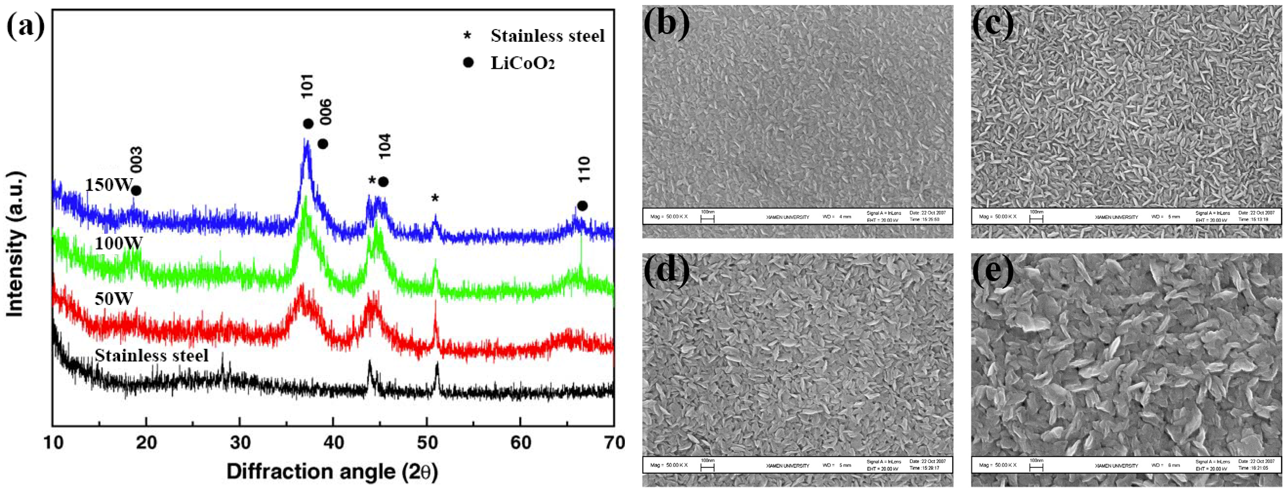
2.3. Sputtering Power

The post-annealing treatment at high temperature is often accompanied by the reaction between the cathode material and current collecting substrate, which will cause irreversible phase transition upon cycling (Figure 2b) [52]. Therefore, the crystalline of the LCO film without high-temperature treatment becomes a key problem, which could be mitigated by changing the sputtering power.
Jeon et al. [53] used RF magnetron sputtering to deposit the LCO film on the SS substrate by varying the sputtering power from 50 to 150 W. After deposition, the films show the preferred orientations of (101) and (104). As shown in Figure 3a, with the increase of sputtering power, the crystallinity of (101) and (104) LCO becomes stronger, which is favorable for improving the lithium transportation. Pan et al. [54] compared the surface morphology of LCO films deposited by different RF sputtering power. As shown in Figure 3b–e, the as-deposited films at different power are smooth and crack-free, but the particles become bigger with the increase in sputtering power. After 25 cycles, the capacity retention of LCO films fabricated at 150 and 200 W exceeds 88%, while that of other films prepared at lower power (80 and 100 W) is only ~65%, indicating that increasing the sputtering power can enhance the cycle stability of LCO films. The bias sputtering of LCO is also an effective way to fabricate crystalline LCO films. The enhanced electrochemical properties by the substrate bias are associated with the microscale structural changes due to the ion bombardment, delivering energy to the deposited films. Tintignac et al. [55] obtained crack-free LCO films by a combination of biased sputtering and post-annealing. It is also proven that the de-lithiation process is highly reversible in the LCO films fabricated by biased sputtering.

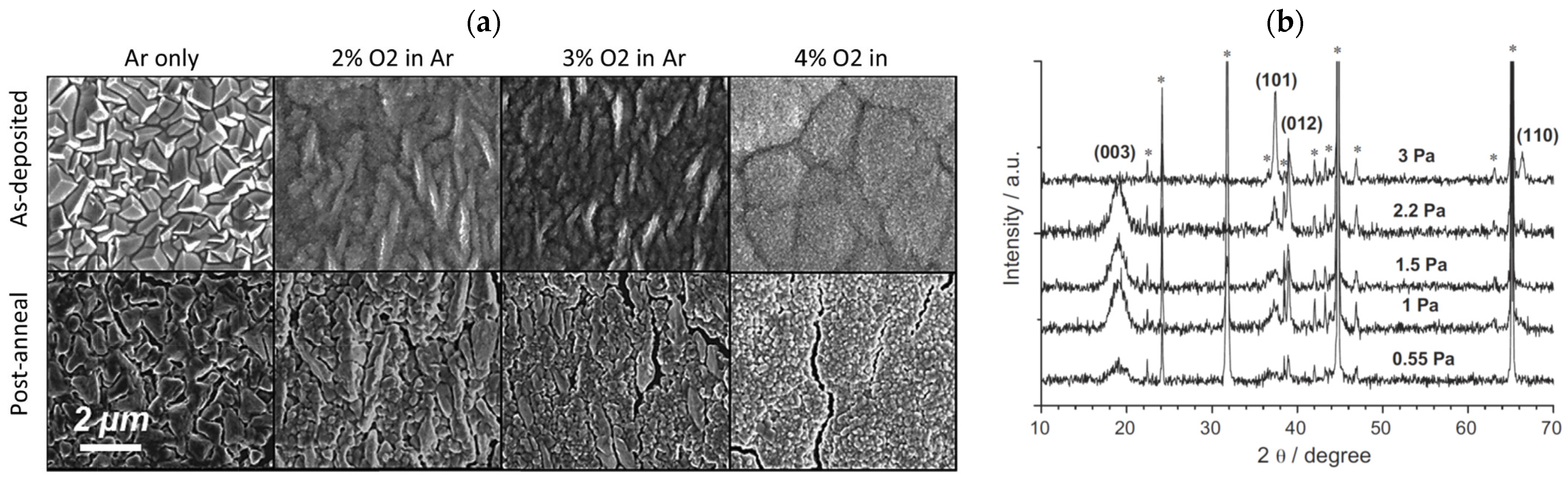
2.4. Sputtering Atmosphere

Ar is an inert atmosphere to provide the ions for sputtering the target, while oxygen acts as a reactive gas for oxidizing the metal target, thus promoting the generation of the LCO film. Trask et al. analyzed the effect of different O2 contents on the LCO deposition. The addition of O2 into the Ar induces a fine grain structure of LCO, resulting into similar morphological changes after high-temperature annealing.
Jason et al. [56] studied the microstructure evolution of LCO films by varying the sputtering atmosphere and noted the reduced grain size and absence of the large cubic grains in the 4% O2 condition (Figure 4a). Without sufficient partial pressure of O2, when the film is larger than 5 μm, the LCO begins to have large and cubic Li-Co3O4 grains with a tightly packed (333) plane parallel to the film. When oxygen is present in the sputtering gas, the LCO film becomes rich in oxygen, thus inhibiting the growth of closed Co3O4 grains, and finer grains appear. With the increasing content of O2, the cycling performance is also gradually increased. The LCO prepared under the conditions of 2%, 3%, and 4% O2 maintains ~85% of the initial capacity at 0.1C for 100 cycles. The LCO film made under 4% O2 conditions shows an enhanced cycle performance of 95% capacity retention after 100 cycles. For the pure Ar atmosphere, the L shows single close-packed texture grains. As the O2 content increases, the as-deposited films become fine grains as a result of the mitigation of volume strain due to the mismatch of LCO and substrate. Tintignac et al. [57] revealed a stratified HT-LCO and cubic LT-LCO in the LCO films and measured the relative content of the two compounds, demonstrating the increase of the layered HT-LCO phase by increasing the gas pressure (Figure 4b). The systematic presence of residual Co3O4 indicates the compositional evolution of LCO film by regulating the working pressure.

3. LiCoO2 Thin Films Fabricated by Other Methods

3.1. Spin Coating and Sol–Gel Methods

High-quality LCO films have been obtained by magnetron sputtering methods. However, it is difficult to use those methods to produce large-area and high-quality films due to high cost, restricted conditions, and long production times. Wet chemistry process offers a low-cost opportunity for mass production of LCO films.
Kwon et al. [58] achieved the epitaxial growth of LCO films by spin coating, and the c axis orientation of LCO [1–10] are parallel to the [100] sapphire substrate. By a two-step process of heating and post-annealing, the LCO film can be promoted to grow in different orientations. Porthault et al. [59] synthesized the LCO thin films by a sol–gel method using acrylic acid (AA) as the chelating agent. The gelation process is optimized by changing the solvents (ethylene glycol and water) and precursor (Li, Co, and AA) molar ratio, and the films are deposited on Au/TiO2/SixN/SiO2/Si substrate by spin coating. The films are deposited by multiple steps to increase the density and calcined at 800 °C for 5 h, successfully forming the R-3m phase HT-LCO film with superior electrochemical performance.

3.2. Atomic Layer Deposition

ALD is a method for forming thin films by alternately pumping a pulsed gas phase precursor into the reaction chamber and a gas-solid chemisorption reaction occurs on the surface of the substrate. The periodic deposition process contains four steps: First, though the first precursor gas, chemical adsorption and reaction happen on the substrate surface; Second, the remaining gas is flushed with inert gas; Third, through the second precursor gas, the coating is formed by a chemical reaction with the first precursor gas on the substrate surface; Fourth, the excess second precursor gas is washed away by flushing gas and the reaction product is repeated. Unlike chemical vapor deposition (CVD), the PVD process has a limited effect on stepwise deposition in multi-functional structures because the atomic/molecular diffusion and growth face a complex relationship between the substrate and the precursor. However, this effect can be avoided by the ALD method, which is based on the surface saturation, and thus provides the possibility of more complicated substrate structures.
Donders et al. [44] utilized a combination of CoCp2 as the cobalt precursor, LiOtBu as the lithium precursor, and O2 plasma as the oxidant source to deposit LCO films. The HT-LCO film is obtained after the deposition at 325 °C and the annealing at 700 °C. Although the electrochemical test shows that the capacity is only approximately 60% of the theoretical capacity, it provides evidence that ALD can deposit electrochemically active LCO. It also indicates that inactive Li2O may be formed during the deposition of LCO by ALD. Optimizing the electrochemical performance of thin films by adjusting the ratio of Co/Li precursor is considered as an important direction of ALD deposition.

3.3. Pulsed Laser Deposition

PLD is a technique where a target is irradiated with a high-power pulse laser to produce a flume containing atoms and molecules of the target material to be deposited on the substrate to produce a film [60]. This produces high levels of plasma, and the plasma and laser beam continue to function by raising the temperature and pressure along the target surface and inducing directional isothermal adiabatic expansion. Finally, the launched plasma in the rapid cooling adiabatic expansion forms deposition on the substrate. It is easy to ensure the stability of stoichiometry after coating complex materials, and the highly consistent target composition is the significant advantage of PLD.
Shiraki et al. [61] deposited the epitaxial (110) LCO films by PLD on single-crystal Au (110) and Pt (110) substrates. The lattice constant of the c axis in the LCO film on Pt (110) is larger than that on Au (110) substrates. The Li-ion diffusion coefficients in the LCO film on Pt (110) is obviously higher than that in LCO (110) film on Au (110). The root cause of the difference in Li-ion diffusion is the different lattice constant in the epitaxial LCO films.

3.4. Pros and Cons of Each Method

LCO thin films obtained by spin coating have advantages in mass production, but at the same time, the energy density is sacrificed, and the uniformity of thin films is difficult to ensure. ALD can achieve the precise control of thin films in nano-scale and prepare high-tap-density thin films. However, the selection of a precursor is harsh, and the cost is too high for industry, so it is not suitable for mass preparation. PLD has low requirements on the target materials and deposition environment, but the efficiency of large-area deposition is low. Magnetron sputtering, after decades of development, has become a mature technology in industrial production through the control of substrate temperature, sputtering atmosphere, bias control, power control, substrate control, and other optimizations that can maximize the film quality. The magnetron sputtering technology is still one of the most promising methods for preparing LCO films to prevent the influence of deposition variety on the electrochemical and physical properties.

4. Modification of LiCoO2 Cathode

4.1. Bulk Doping

When more than half of the Li-ions are removed, the crystal structure of LCO is easy to collapse and the cycle life is greatly attenuated. Doping transition or non-transition metals is an important way to improve the structural stability of LCO films. It is believed that the influence of transition metal doping on LCO is concentrated on the capacity, while non-transition metal doping mainly affects the de-lithiation potential of LCO.
Dong et al. [62] synthesized the Mn-doped LCO by a molten salt method using NaOH to provide an alkaline environment for making the uniform reactant mixture, enhancing the stability of the valence state of Mn ions while retaining the single-phase nature. It is found that the electrochemical inert Mn4+ can play a supporting role upon cycling, inhibiting the phase transition of LCO at 4.2 V, and significantly improve the structural stability, conductivity and li-ion diffusion rate of LCO. Sun et al. [63] used the positively charged Co(OH)2−xx+ nanoplates and negatively charged Ti2−x/4x/4O4x nanosheets by electrostatic gravity assembly, and calcine them with LiOH to form the Ti-doped LCO. The Ti doping enhances the stability of the structure and inhibits the phase change at the same time. Even at a 4.5 V cut-off voltage, it exhibits a capacity of 205 mAh g−1 and a capacity retention rate of 97% after 200 cycles. Using Mg-doped LCO, Huang et al. [64] found that the Li-Mg mixed structure generated on the surface of Mg-pillared LCO is beneficial to remove the overgrowth of CEI and phase transition near the surface. The Mg-pillared LCO under 0.2C shows the high capacity of 204 mAh g−1 within 3.0–4.6 V (Figure 5a), and at 1.0C, the retention capacity is increased to 84% (Figure 5b). Ganesh et al. [65] deposited a series of LiZrxCo1−xO2 films on the Au/Ti/SiO2/Si (100) substrates using a Zr-doped LCO target. The cathode films show the high initial discharge capacity of 64.4 µAh cm−2 µm−1 with a capacity retention rate of 98.5% after 25 cycles. Ganesh et al. [66] deposited the LiTiyCo1−yO2 (y = 0, 0.02, 0.05, 0.1) films on the Si substrate by magnetron sputtering. The films exhibited preferred (003), (101), and (104) crystal orientations related to the single-phase hexagonal R-3m space group, reducing the charge transfer resistance of Ti-doped LCO films and inducing the high initial capacity of 65 μA h cm−2 μm−1 with a capacity retention of 98% after 25 cycles.

4.2. Surface Coating

Electrode materials and electrolyte interface largely affect the electrochemical performance of TFB. The CEI film is composed of inorganic and organic compounds, which not only determine the cycling life, but also change the electrochemical behavior of cathode materials.
Fingerle et al. [67] investigated the surface chemistry of a sputtered LCO film when contacted with ethyl carbonate (EC) by synchrotron-based soft X-ray photoelectron spectroscopy (SXPS). The electronic and chemical properties of the interface are determined by the progressively adsorbed EC, demonstrating that the decomposition layer is passivated. Li-ions extract from the electrode and dissolve into the electrolyte without forming Li-rich residuals, indicating that the electrolyte reduction remains limited, which may be due to the large offset between the LCO valence band and EC energy band. Noh et al. [68] fabricated bare and ZrO2-coated LCO thin films by DC magnetron sputtering on SS substrates. Both the deposited films have a crystallized structure of (003) preferred crystal orientation after annealed at 600 °C. The ZrO2-coated LCO thin film exhibits improved cycling stability compared to that of the bare LCO film at a high cut-off potential of 4.5 V. Yang et al. [69] coated a 20 nm Li1+xAlxTi2−x(PO4)3 (LATP) solid electrolyte film on the surface of LCO, and found that LATP coating could prevent the reaction between cathode and electrolyte, thereby reducing the dissolution of Co3+ and improving the electrochemical performance of LCO at a high cut-off voltage of 4.5 V. Nie et al. [70] developed a simple wet-mixing method to achieve a thin and uniform Al-doped ZnO coating on the surface of LCO particles, which establishes a stable surface and CEI layer, inhibiting the electrolyte decomposition. At the same time, the coating also provids good ionic conductivity for LCO to achieve high cycling stability at a high voltage of 4.5 V. Huang et al. [71] used a dextran sulfate lithium (DSL) binder instead of a polyvinylidene fluoride (PVDF) binder to uniformly coat the surface of LCO particles. In particular, the combination between the sulfate group of the DSL chain and LCO particles increases the stability of the Co-O bonds. The harmful phase transition generated in LCO above 4.55 V is inhibited (Figure 5c) and the interfacial resistance after cycling is also reduced (Figure 5d). The cut-off voltage of LCO electrodes has been increased from the initial 4.2 to present 4.6 V as listed in Table 1, and its actual discharge capacity gradually has increased from 140 to 220 mAh g−1.

5. Conclusions and Perspective

Currently, LCO thin films are the best candidate to be cathode materials for LIB, and especially TFB, due to their high volumetric capacity and high working voltage. Among them, most LCO thin films are fabricated by magnetron sputtering and the experiment parameters largely affect the deposition and performance. Specifically, the heating process can increase the crystallinity but generate internal stress, which should be properly regulated for realizing high capacity and good durability. The substrate may induce the preferred orientations of deposited LCO films. The sputtering power and atmosphere are the key parameters for simultaneously tuning the morphology and crystal orientation of LCO films. For the LCO films deposited by other techniques (spin coating, sol–gel, ALD, PLD, etc.), the crystal structure may be further optimized when combined with a heating process, and high-loading films for mass production could be obtained through those techniques. To further improve the electrochemical property of powder and thin-film LCO, bulk doping and surface coating are both effective strategies for increasing the reversible capacity and protecting the surface. In practice, the multiple optimization strategies of doping, coating, and nano-structuring are necessary for fully utilizing state-of-the-art LCO films. In the future, novel materials, structures, and techniques need to be developed, such as the elimination of an annealing process for the integration with on-chip devices; the stacking structure of thin films for achieving high energy density; or the all-in-one integration of energy conversion and storage devices for the next-generation portable electronics.

Author Contributions

Conceptualization, Z.D. and J.L.; validation, L.W. and D.-L.P.; formal analysis, J.L.; investigation, Z.D.; data curation, Y.W.; writing—original draft preparation, Z.D.; writing—review and editing, J.L.; visualization, L.W.; supervision, D.-L.P.; project administration, D.-L.P.; funding acquisition, J.L. and D.-L.P. All authors have read and agreed to the published version of the manuscript.

Funding

This work was supported by National Natural Science Foundation of China (Nos. 52101273 and 51931006), Natural Science Foundation of Fujian Province of China (No. 2020J05014), Fundamental Research Funds for the Central Universities of China (Nos. 20720220106 and 20720200080).

Conflicts of Interest

The authors declare no conflict of interest.

References

  1. Park, H.Y.; Lee, S.R.; Lee, Y.J.; Cho, B.W.; Cho, W.I. Bias Sputtering and Characterization of LiCoO2 Thin Film Cathodes for Thin Film Microbattery. Mater. Chem. Phys. 2005, 93, 70–78. [Google Scholar] [CrossRef]
  2. Pan, X.; Hong, X.; Xu, L.; Li, Y.; Yan, M.; Mai, L. On-Chip Micro/Nano Devices for Energy Conversion and Storage. Nano Today 2019, 28, 100764. [Google Scholar]
  3. Mai, L.; Sheng, J.; Xu, L.; Tan, S.; Meng, J. One-Dimensional Hetero-Nanostructures for Rechargeable Batteries. Acc. Chem. Res. 2018, 51, 950–959. [Google Scholar] [CrossRef] [PubMed]
  4. Zhou, L.; Zhang, K.; Hu, Z.; Tao, Z.; Mai, L.; Kang, Y.-M.; Chou, S.-L.; Chen, J. Recent Developments on and Prospects for Electrode Materials with Hierarchical Structures for Lithium-Ion Batteries. Adv. Energy Mater. 2018, 8, 1701415. [Google Scholar] [CrossRef]
  5. Goodenough, J.B.; Kim, Y. Challenges for Rechargeable Li Batteries. Chem. Mater. 2009, 22, 587–603. [Google Scholar] [CrossRef]
  6. Mizushima, K.; Jones, P.C.; Wiseman, P.J.; Goodenough, J.B. Lixcoo2 (0 < X < −1): A New Cathode Material for Batteries of High Energy Density. Mater. Res. Bull. 1980, 15, 783–789. [Google Scholar]
  7. Muldoon, J.; Bucur, C.B.; Gregory, T. Quest for Nonaqueous Multivalent Secondary Batteries: Magnesium and Beyond. Chem. Rev. 2014, 114, 11683–11720. [Google Scholar] [CrossRef] [PubMed]
  8. Goodenough, J.B.; Park, K.S. The Li-Ion Rechargeable Battery: A Perspective. J. Am. Chem. Soc. 2013, 135, 1167–1176. [Google Scholar] [CrossRef] [PubMed]
  9. Wang, K.; Wan, J.; Xiang, Y.; Zhu, J.; Leng, Q.; Wang, M.; Xu, L.; Yang, Y. Recent Advances and Historical Developments of High Voltage Lithium Cobalt Oxide Materials for Rechargeable Li-Ion Batteries. J. Power Sources 2020, 460, 228062. [Google Scholar] [CrossRef]
  10. Smith, A.J.; Dahn, H.M.; Burns, J.C.; Dahn, J.R. Long-Term Low-Rate Cycling of LiCoO2/Graphite Li-Ion Cells at 55 °C. J. Electrochem. Soc. 2012, 159, A705–A710. [Google Scholar] [CrossRef]
  11. He, P.; Yu, H.; Li, D.; Zhou, H. Layered Lithium Transition Metal Oxide Cathodes Towards High Energy Lithium-Ion Batteries. J. Mater. Chem. 2012, 22, 3680–3695. [Google Scholar] [CrossRef]
  12. Chikkannanavar, S.B.; Bernardi, D.M.; Liu, L. A Review of Blended Cathode Materials for Use in Li-Ion Batteries. J. Power Sources 2014, 248, 91–100. [Google Scholar] [CrossRef]
  13. Ohzuku, T.; Ueda, A. Solid-State Redox Reactions of LiCoO2 (R3m) for 4 Volt Secondary Lithium Cells. J. Electrochem. Soc. 1994, 141, 2972–2977. [Google Scholar] [CrossRef]
  14. Li, C.; Zhang, H.P.; Fu, L.J.; Liu, H.; Wu, Y.P.; Rahm, E.; Holze, R.; Wu, H.Q. Cathode Materials Modified by Surface Coating for Lithium Ion Batteries. Electrochim. Acta 2006, 51, 3872–3883. [Google Scholar] [CrossRef]
  15. Park, J.S.; Mane, A.U.; Elam, J.W.; Croy, J.R. Amorphous Metal Fluoride Passivation Coatings Prepared by Atomic Layer Deposition on LiCoO2 for Li-Ion Batteries. Chem. Mater. 2015, 27, 1917–1920. [Google Scholar] [CrossRef]
  16. Crabtree, G.; Kócs, E.; Trahey, L. The Energy-Storage Frontier: Lithium-Ion Batteries and Beyond. MRS Bull. 2015, 40, 1067–1078. [Google Scholar] [CrossRef] [Green Version]
  17. Xu, K. Electrolytes and Interphases in Li-Ion Batteries and Beyond. Chem. Rev. 2014, 114, 11503–11618. [Google Scholar] [CrossRef]
  18. Chen, Z.; Dahn, J.R. Methods to Obtain Excellent Capacity Retention in LiCoO2 Cycled to 4.5 V. Electrochim. Acta 2004, 49, 1079–1090. [Google Scholar] [CrossRef]
  19. Choi, N.-S.; Han, J.-G.; Ha, S.-Y.; Park, I.; Back, C.-K. Recent Advances in the Electrolytes for Interfacial Stability of High-Voltage Cathodes in Lithium-Ion Batteries. RSC Adv. 2015, 5, 2732–2748. [Google Scholar] [CrossRef]
  20. Sharifi-Asl, S.; Lu, J.; Amine, K.; Shahbazian-Yassar, R. Oxygen Release Degradation in Li-Ion Battery Cathode Materials: Mechanisms and Mitigating Approaches. Adv. Energy Mater. 2019, 9, 1900551. [Google Scholar] [CrossRef]
  21. Zhou, A.; Dai, X.; Lu, Y.; Wang, Q.; Fu, M.; Li, J. Enhanced Interfacial Kinetics and High-Voltage/High-Rate Performance of LiCoO2 Cathode by Controlled Sputter-Coating with a Nanoscale Li4ti5o12 Ionic Conductor. ACS Appl. Mater. Interfaces 2016, 8, 34123–34131. [Google Scholar] [CrossRef]
  22. Aboulaich, A.; Ouzaouit, K.; Faqir, H.; Kaddami, A.; Benzakour, I.; Akalay, I. Improving Thermal and Electrochemical Performances of Licoo 2 Cathode at High Cut-Off Charge Potentials by Mf 3 (M = Ce, Al) Coating. Mater. Res. Bull. 2016, 73, 362–368. [Google Scholar] [CrossRef]
  23. Xia, L.; Xia, Y.; Liu, Z. Thiophene Derivatives as Novel Functional Additives for High-Voltage LiCoO2 Operations in Lithium Ion Batteries. Electrochim. Acta 2015, 151, 429–436. [Google Scholar] [CrossRef]
  24. Hayashi, M.; Takahashi, M.; Sakurai, Y. Preparation of Positive LiCoO2 Films by Electron Cyclotron Resonance (Ecr) Plasma Sputtering Method and Its Application to All-Solid-State Thin-Film Lithium Batteries. J. Power Sources 2007, 174, 990–995. [Google Scholar] [CrossRef]
  25. Takahashi, M.; Hayashi, M.; Shodai, T. Characterization of All-Solid-State Secondary Batteries with LiCoO2 Thin Films Prepared by Ecr Sputtering as Positive Electrodes. J. Power Sources 2009, 189, 191–196. [Google Scholar] [CrossRef]
  26. Wang, Z.; Lee, J.Z.; Xin, H.L.; Han, L.; Grillon, N.; Guy-Bouyssou, D.; Bouyssou, E.; Proust, M.; Meng, Y.S. Effects of Cathode Electrolyte Interfacial (Cei) Layer on Long Term Cycling of All-Solid-State Thin-Film Batteries. J. Power Sources 2016, 324, 342–348. [Google Scholar] [CrossRef] [Green Version]
  27. Kim, H.S.; Oh, Y.; Kang, K.H.; Kim, J.H.; Kim, J.; Yoon, C.S. Characterization of Sputter-Deposited LiCoO2 Thin Film Grown on Nasicon-Type Electrolyte for Application in All-Solid-State Rechargeable Lithium Battery. ACS Appl. Mater. Interfaces 2017, 9, 16063–16070. [Google Scholar] [CrossRef]
  28. Lidor-Shalev, O.; Leifer, N.; Ejgenberg, M.; Aviv, H.; Perelshtein, I.; Goobes, G.; Noked, M. Rosy, Molecular Layer Deposition of Alucone Thin Film on LiCoO2 to Enable High Voltage Operation. Batter. Supercaps 2021, 4, 1739–1748. [Google Scholar] [CrossRef]
  29. Kutbee, A.T.; Ghoneim, M.T.; Ahmad, S.M.; Hussain, M.M. Free-Form Flexible Lithium-Ion Microbattery. IEEE Trans. Nanotechnol. 2016, 15, 402–408. [Google Scholar] [CrossRef] [Green Version]
  30. Lin, J.; Lin, L.; Qu, S.; Deng, D.; Wu, Y.; Yan, X.; Xie, Q.; Wang, L.; Peng, D. Promising Electrode and Electrolyte Materials for High-Energy-Density Thin-Film Lithium Batteries. Energy Environ. Mater. 2021, 5, 133–156. [Google Scholar] [CrossRef]
  31. Krówka, K.; Wiatrowski, A.; Posadowski, W.M. Magnetron Sputtering Modes During Pulsed Deposition Process Determined by the Analysis of Power Supply Parameter. Thin Solid Film. 2012, 520, 4127–4130. [Google Scholar] [CrossRef]
  32. Julien, C.M.; Mauger, A.; Hussain, O.M. Sputtered LiCoO2 Cathode Materials for All-Solid-State Thin-Film Lithium Microbatteries. Materials 2019, 12, 2687. [Google Scholar] [CrossRef]
  33. Lu, W.; Zhang, J.; Xu, J.; Wu, X.; Chen, L. In Situ Visualized Cathode Electrolyte Interphase on LiCoO2 in High Voltage Cycling. ACS Appl. Mater. Interfaces 2017, 9, 19313–19318. [Google Scholar] [CrossRef]
  34. Liao, C.-L.; Lee, Y.-H.; Fung, K.-Z. The Film Growth and Electrochemical Properties of Rf-Sputtered LiCoO2 Thin Films. J. Alloys Compd. 2007, 436, 303–308. [Google Scholar] [CrossRef]
  35. HakanYudar, H.; Pat, S.; Özen, S.; Mohammadigharehbagh, R.; Musaoğlu, C.; Korkmaz, Ş.; Pat, Z. Microstructural, Surface and Electrochemical Properties of the Nano Layered LiCoO2 Thin Film Cathode for Li Ion Battery. Vacuum 2018, 152, 248–251. [Google Scholar] [CrossRef]
  36. Joo, H.; Lee, H.; Cho, G.; Nam, T.; Huh, S.; Choi, B.; Jueong, H.; Noh, J. Influence of the Metal-Induced Crystallization on the Structural and Electrochemical Properties of Sputtered LiCoO2 Thin Films. Thin Solid Film. 2017, 641, 53–58. [Google Scholar] [CrossRef]
  37. Pan, R.; Rau, D.; Moryson, Y.; Sann, J.; Janek, J. Reversible Capacity Loss of LiCoO2 Thin Film Electrodes. ACS Appl. Energy Mater. 2020, 3, 6065–6071. [Google Scholar] [CrossRef]
  38. Liao, C.-L.; Fung, K.-Z. Lithium Cobalt Oxide Cathode Film Prepared by Rf Sputtering. J. Power Sources 2004, 128, 263–269. [Google Scholar] [CrossRef]
  39. Jung, K.-T.; Cho, G.-B.; Kim, K.-W.; Nam, T.-H.; Jeong, H.-M.; Huh, S.-C.; Chung, H.-S.; Noh, J.-P. Influence of the Substrate Texture on the Structural and Electrochemical Properties of Sputtered LiCoO2 Thin Films. Thin Solid Film. 2013, 546, 414–417. [Google Scholar] [CrossRef]
  40. Jayanth-Babu, K.; Jeevan-Kumar, P.; Hussain, O.M.; Julien, C.M. Influence of Annealing Temperature on Microstructural and Electrochemical Properties of Rf-Sputtered Limn2o4 Film Cathodes. J. Solid State Electrochem. 2012, 16, 3383–3390. [Google Scholar] [CrossRef]
  41. Noh, J.-P.; Cho, G.-B.; Jung, K.-T.; Kang, W.-G.; Ha, C.-W.; Ahn, H.-J.; Ahn, J.-H.; Nam, T.-H.; Kim, K.-W. Fabrication of LiCoO2 Thin Film Cathodes by Dc Magnetron Sputtering Method. Mater. Res. Bull. 2012, 47, 2823–2826. [Google Scholar] [CrossRef]
  42. Tintignac, S.; Baddour-Hadjean, R.; Pereira-Ramos, J.P.; Salot, R. Electrochemical Properties of High Rate Bias Sputtered LiCoO2 Thin Films in Liquid Electrolyte. J. Power Sources 2014, 245, 76–82. [Google Scholar] [CrossRef]
  43. Xia, H.; Wan, Y.; Assenmacher, W.; Mader, W.; Yuan, G.; Lu, L. Facile Synthesis of Chain-Like LiCoO2 Nanowire Arrays as Three-Dimensional Cathode for Microbatteries. NPG Asia Mater. 2014, 6, e126. [Google Scholar] [CrossRef] [Green Version]
  44. Donders, M.E.; Arnoldbik, W.M.; Knoops, H.C.M.; Kessels, W.M.M.; Notten, P.H.L. Atomic Layer Deposition of LiCoO2 thin-Film Electrodes for All-Solid-State Li-Ion Micro-Batteries. J. Electrochem. Soc. 2013, 160, A3066–A3071. [Google Scholar] [CrossRef] [Green Version]
  45. Shiraki, S.; Oki, H.; Takagi, Y.; Suzuki, T.; Kumatani, A.; Shimizu, R.; Haruta, M.; Ohsawa, T.; Sato, Y.; Ikuhara, Y.; et al. Fabrication of All-Solid-State Battery Using Epitaxial LiCoO2 Thin Films. J. Power Sources 2014, 267, 881–887. [Google Scholar] [CrossRef]
  46. Turrell, S.J.; Zekoll, S.; Liu, J.; Grovenor, C.R.M.; Speller, S.C. Optimization of a Potential Manufacturing Process for Thin-Film LiCoO2 Cathodes. Thin Solid Film. 2021, 735, 138888. [Google Scholar] [CrossRef]
  47. Ma, Y.; Chen, M.; Yan, Y.; Wei, Y.; Liu, W.; Zhang, X.; Li, J.; Fu, Z.; Li, J.; Zhang, X. Annealing of LiCoO2 Films on Flexible Stainless Steel for Thin Film Lithium Batteries. J. Mater. Res. 2019, 35, 31–41. [Google Scholar] [CrossRef]
  48. Wu, T.; Zhao, Y.; Zhang, X.; Ma, S.; Wei, K.; Wei, Y.; Cui, Y. Improved Solid Interfacial Kinetics and Electrochemical Performance for LiCoO2(1 1 0) Textured Thin-Film Lithium Batteries. Appl. Surf. Sci. 2022, 591, 153174. [Google Scholar] [CrossRef]
  49. Shiraki, S.; Takagi, Y.; Shimizu, R.; Suzuki, T.; Haruta, M.; Sato, Y.; Ikuhara, Y.; Hitosugi, T. Orientation Control of LiCoO2 Epitaxial Thin Films on Metal Substrates. Thin Solid Film. 2016, 600, 175–178. [Google Scholar] [CrossRef] [Green Version]
  50. Bohne, L.; Pirk, T.; Jaegermann, W. Investigations on the Influence of the Substrate on the Crystal Structure of Sputtered LiCoO2. J. Solid State Electrochem. 2011, 17, 2095–2099. [Google Scholar] [CrossRef]
  51. Yoon, Y.; Park, C.; Kim, J.; Shin, D. Lattice Orientation Control of Lithium Cobalt Oxide Cathode Film for All-Solid-State Thin Film Batteries. J. Power Sources 2013, 226, 186–190. [Google Scholar] [CrossRef]
  52. Wang, L.; Chen, B.; Ma, J.; Cui, G.; Chen, L. Reviving Lithium Cobalt Oxide-Based Lithium Secondary Batteries-toward a Higher Energy Density. Chem. Soc. Rev. 2018, 47, 6505–6602. [Google Scholar] [CrossRef]
  53. Jeon, S.-W.; Lim, J.-K.; Lim, S.-H.; Lee, S.-M. As-Deposited LiCoO2 Thin Film Cathodes Prepared by Rf Magnetron Sputtering. Electrochim. Acta 2005, 51, 268–273. [Google Scholar] [CrossRef]
  54. Pan, H.; Yang, Y. Effects of Radio-Frequency Sputtering Powers on the Microstructures and Electrochemical Properties of LiCoO2 Thin Film Electrodes. J. Power Sources 2009, 189, 633–637. [Google Scholar] [CrossRef]
  55. Tintignac, S.; Baddour-Hadjean, R.; Pereira-Ramos, J.P.; Salot, R. High Rate Bias Sputtered Licoo 2 Thinfilms as Positive Electrode for All-Solid-State Lithium Microbatteries. Electrochim. Acta 2014, 146, 472–476. [Google Scholar] [CrossRef]
  56. Trask, J.; Anapolsky, A.; Cardozo, B.; Januar, E.; Kumar, K.; Miller, M.; Brown, R.; Bhardwaj, R. Optimization of 10-Μm, Sputtered, Licoo 2 Cathodes to Enable Higher Energy Density Solid State Batteries. J. Power Sources 2017, 350, 56–64. [Google Scholar] [CrossRef]
  57. Tintignac, S.; Baddour-Hadjean, R.; Pereira-Ramos, J.-P.; Salot, R. High Performance Sputtered LiCoO2 Thin Films Obtained at a Moderate Annealing Treatment Combined to a Bias Effect. Electrochim. Acta 2012, 60, 121–129. [Google Scholar] [CrossRef]
  58. Kwon, T.; Ohnishi, T.; Mitsuishi, K.; Ozawa, T.C.; Takada, K. Synthesis of LiCoO2 Epitaxial Thin Films Using a Sol–Gel Method. J. Power Sources 2015, 274, 417–423. [Google Scholar] [CrossRef]
  59. Porthault, H.; Le Cras, F.; Franger, S. Synthesis of LiCoO2 Thin Films by Sol/Gel Process. J. Power Sources 2010, 195, 6262–6267. [Google Scholar] [CrossRef]
  60. Nandihalli, N. Thermoelectric Films and Periodic Structures and Spin Seebeck Effect Systems: Facets of Performance Optimization. Mater. Today Energy 2022, 25, 100965. [Google Scholar] [CrossRef]
  61. Shiraki, S.; Oki, H.; Hitosugi, T. Li Diffusion in (110)-Oriented LiCoO2 Thin Films Grown on Au and Pt (110) Substrates. Surface Interface Anal. 2016, 48, 1240–1243. [Google Scholar] [CrossRef]
  62. Luo, D.; Li, G.; Yu, C.; Yang, L.; Zheng, J.; Guan, X.; Li, L. Low-Concentration Donor-Doped LiCoO2 as a High Performance Cathode Material for Li-Ion Batteries to Operate between −10.4 and 45.4 °C. J. Mater. Chem. 2012, 22, 22233–22241. [Google Scholar] [CrossRef]
  63. Sun, L.; Zhang, Z.; Hu, X.; Tian, H.; Zhang, Y.; Yang, X. Realization of Ti Doping by Electrostatic Assembly to Improve the Stability of LiCoO2 Cycled to 4.5 v. J. Electrochem. Soc. 2019, 166, A1793–A1798. [Google Scholar] [CrossRef]
  64. Huang, Y.; Zhu, Y.; Fu, H.; Ou, M.; Hu, C.; Yu, S.; Hu, Z.; Chen, C.T.; Jiang, G.; Gu, H.; et al. Mg-Pillared LiCoO2: Towards Stable Cycling at 4.6 V. Angew. Chem. Int. Ed. Engl. 2021, 60, 4682–4688. [Google Scholar] [CrossRef] [PubMed]
  65. Ganesh, K.S.; Reddy, B.P.; Kumar, P.J.; Hussain, O.M. Influence of Zr Dopant on Microstructural and Electrochemical Properties of LiCoO2 Thin Film Cathodes by Rf Sputtering. J. Electroanal. Chem. 2018, 828, 71–79. [Google Scholar] [CrossRef]
  66. Ganesh, K.S.; Reddy, B.P.; Kumar, P.J.; Jayanthbabu, K.; Rosaiah, P.; Hussain, O.M. Microstructural and Electrochemical Properties of Liti Y Co 1-Y O2 Film Cathodes Prepared by Rf Sputtering. J. Solid State Electrochem. 2015, 19, 3621–3627. [Google Scholar] [CrossRef]
  67. Fingerle, M.; Späth, T.; Schulz, N.; Hausbrand, R. Adsorption of Ethylene Carbonate on Lithium Cobalt Oxide Thin Films: A Synchrotron-Based Spectroscopic Study of the Surface Chemistry. Chem. Phys. 2017, 498–499, 19–24. [Google Scholar] [CrossRef]
  68. Noh, J.-P.; Jung, K.-T.; Jang, M.-S.; Kwon, T.-H.; Cho, G.-B.; Kim, K.-W.; Nam, T.-H. Protection Effect of ZrO2 Coating Layer on LiCoO2 Thin Film Fabricated by Dc Magnetron Sputtering. J. Nanosci. Nanotechnol. 2013, 13, 7152–7154. [Google Scholar] [CrossRef]
  69. Yang, Q.; Huang, J.; Li, Y.; Wang, Y.; Qiu, J.; Zhang, J.; Yu, H.; Yu, X.; Li, H.; Chen, L. Surface-Protected LiCoO2 with Ultrathin Solid Oxide Electrolyte Film for High-Voltage Lithium Ion Batteries and Lithium Polymer Batteries. J. Power Sources 2018, 388, 65–70. [Google Scholar] [CrossRef]
  70. Nie, K.; Sun, X.; Wang, J.; Wang, Y.; Qi, W.; Xiao, D.; Zhang, J.-N.; Xiao, R.; Yu, X.; Li, H.; et al. Realizing Long-Term Cycling Stability and Superior Rate Performance of 4.5 v–LiCoO2 by Aluminum Doped Zinc Oxide Coating Achieved by a Simple Wet-Mixing Method. J. Power Sources 2020, 470, 228423. [Google Scholar] [CrossRef]
  71. Huang, H.; Li, Z.; Gu, S.; Bian, J.; Li, Y.; Chen, J.; Liao, K.; Gan, Q.; Wang, Y.; Wu, S.; et al. Dextran Sulfate Lithium as Versatile Binder to Stabilize High-Voltage LiCoO2 to 4.6 V. Adv. Energy Mater. 2021, 11, 2101864. [Google Scholar] [CrossRef]
  72. Kim, J.; Kang, H.; Go, N.; Jeong, S.; Yim, T.; Jo, Y.N.; Lee, K.T.; Mun, J. Egg-Shell Structured LiCoO2 by Cu2+ Substitution to Li+ Sites Via Facile Stirring in an Aqueous Copper(Ii) Nitrate Solution. J. Mater. Chem. A 2017, 5, 24892–24900. [Google Scholar] [CrossRef]
  73. Qian, J.; Liu, L.; Yang, J.; Li, S.; Wang, X.; Zhuang, H.L.; Lu, Y. Electrochemical Surface Passivation of LiCoO2 Particles at Ultrahigh Voltage and Its Applications in Lithium-Based Batteries. Nat. Commun. 2018, 9, 4918. [Google Scholar] [CrossRef]
Figure 1. (a) XRD patterns of as-deposited and annealed LCO films at different temperatures. Peak labels of HT-LCO and substrates are abbreviated to HT and S, respectively. (b) XRD pattern of LCO powder from its LCO target. Reproduced with permission [46]. Copyright 2021, Elsevier.
Energies 15 08980 g001
Figure 2. (a) Scheme of LCO(003)/LiPON/Li and LCO(110)/LiPON/Li thin-film lithium batteries. Reproduced with permission [48]. Copyright 2022, Elsevier. (b) Variations in the a and c parameters and phases during Li-ion extraction from LCO electrodes. Reproduced with permission [52]. Copyright 2018, Royal Society of Chemistry.
Energies 15 08980 g002
Figure 3. (a) XRD patterns of LCO films fabricated at different RF sputtering powers. Reproduced with permission [53]. Copyright 2005, Elsevier. SEM images of as-deposited LCO films on the Pt-substrate fabricated at different RF sputtering powers of (b) 80, (c) 100, (d) 150, and (e) 200 W. Reproduced with permission [54]. Copyright 2009, Elsevier.
Energies 15 08980 g003
Figure 4. (a) SEM images of 10 μm thick LCO films on Au-coated Al substrate fabricated under different atmosphere and annealing condition. Reproduced with permission [56]. Copyright 2017, Elsevier. XRD patterns of (b) LCO films deposited at different working gas pressure. * means substrate peaks. Reproduced with permission [57]. Copyright 2012, Elsevier.
Energies 15 08980 g004
Figure 5. (a) Charge/discharge curves and (b) cycling performance of Mg-doped LCO electrodes. (c) Cyclic voltammetry curves and (d) electrochemical impedance spectra of PVDF-LCO and DSL-LCO.
Energies 15 08980 g005
Table 1. Capacity performance of modified high-voltage LCO electrodes.
MethodsMaterialsVoltage (V)C-RateCyclesCapacity RetentionReference
DopingCu4.42.0C50078.7%[72]
Ti4.51.0C20097.0%[63]
Mg4.61.0C10084.0%[64]
CoatingLATP4.50.2C5093.2%[69]
Al-Zn-O4.50.2C65080.0%[70]
Li-Al-F4.60.1C10089.1%[73]
Publisher’s Note: MDPI stays neutral with regard to jurisdictional claims in published maps and institutional affiliations.

