Article

Effects of Negative Sequence Voltage Subharmonics on Cage Induction Motors

1
Department of Ship Electrical Power Engineering, Faculty of Marine Electrical Engineering, Gdynia Maritime University, Morska St. 83, 81-225 Gdynia, Poland
2
Diagnostic and Service of Electric Motors Department, Zakład Maszyn Elektrycznych “EMIT” Cantoni Group, Narutowicza St. 72, 99-320 Żychlin, Poland
3
Department of Ship Automation, Faculty of Marine Electrical Engineering, Gdynia Maritime University, Morska St. 83, 81-225 Gdynia, Poland
*
Author to whom correspondence should be addressed.
Energies 2022, 15(23), 8797; https://doi.org/10.3390/en15238797
Submission received: 3 October 2022 / Revised: 10 November 2022 / Accepted: 16 November 2022 / Published: 22 November 2022
(This article belongs to the Special Issue Power Quality and Electrical Machines)

Abstract

:
In some power systems, voltage waveforms contain, apart from harmonics, interharmonics and subharmonics that are components of frequency less than or not an integer multiple of the fundamental frequency. Voltage subharmonics and interharmonics may be of both a positive and negative sequence, independently of their frequency. Previous papers on induction motors under subharmonics have been generally limited to the components of a positive sequence. This study deals with the effect of negative sequence subharmonics on the work of induction motors. Investigations were performed using the 2D finite element method and an experimental method. Differences between the impact of positive and negative sequence subharmonics are discussed. It was found that negative sequence voltage subharmonics can result in significant current subharmonics, torque pulsations and vibration. Further, because of possible resonance, motors that are comparatively resistant to positive sequence subharmonics might be especially sensitive to negative sequence subharmonics of the same frequency and vice versa.

1. Introduction

Voltage waveforms in public and industrial power networks commonly contain various undesirable components—usually voltage harmonics. Apart from harmonics, they could also contain subharmonics and interharmonics, which are components of frequency that less than or not an integer multiple of the fundamental frequency. Subharmonics (subsynchronous interharmonics) are often considered as a special case of interharmonics. However, in some studies (for instance [1,2,3,4]), they are regarded separately as they exert a specific impact on electrical equipment [5].
Voltage subharmonics (VShs) are generated by renewable sources of energy such as wind power stations [5,6,7,8] and photovoltaic plants [9,10,11], by double frequency systems such as high voltage DC links and inverters [3,12,13,14,15,16], and also by cycloconverters [3,15], arc furnaces [3,15,17] and pulsating loads [3,15,16,18,19]. Voltage subharmonics can also occur in the voltage produced by inverters [4,20,21]. Notably, cyclic voltage fluctuations are considered as a superposition of the fundamental, subharmonic and interharmonic components [5,22,23,24]. It is also worth mentioning that in some systems, VShs reach levels of about 1% of the fundamental component, for example in [8,13,25].
VShs exert an extraordinarily negative effect on various types of electrical equipment. They disrupt the work of light sources, power and measurement transformers, power electronics and control equipment as well as rotating machinery [1,2,3,4,20,21,22,23,24,26,27,28,29,30,31,32,33,34,35]. In induction motors, VShs cause a local saturation of magnetic circuits [30], speed fluctuations [4,23,24,28,29,30,31], increases in power losses and overheating [3,20,26,27,28,31,33,34,35], and torque pulsations [21,23,27,28,29,31], which may result in vibration of an extremely high level [2]. To make the matter worse, the frequency of torque pulsations may correspond to the natural frequency of the first elastic-mode of the rotating mass [21,31], leading to resonance phenomena. Elastic-mode resonance [21,36] causes, among others, a magnification of torque pulsations, possibly even by a factor exceeding 100 [21]. Consequently, apparently inconsiderable torque pulsations may, after their amplification, result in destruction of a power train [21]. Ref. [21] reported fluctuations of the output voltage of an inverter, causing small torque pulsations (1.5% peak-to-peak). Under resonance the torque pulsations were magnified by the factor of 110, resulting in a coupling failure.
Although VShs are regarded as extraordinarily harmful, their permissible levels have not been introduced into power quality standards. The main reason is the lack of sufficient data to determine the permissible levels. For example, the standard EN 50160 Voltage characteristics of electricity supplied by public distribution systems [37] contains the following comment (concerning both subsynchronous and supersynchronous interharmonics): “The level of interharmonics is increasing due to development of the application of frequency converters and similar control equipment. Levels are under consideration, pending more experience”. Similarly, in an informative annex of the standard IEEE-519: IEEE Recommended practices and requirements for harmonic control in electric power systems [38], the limits are provided together with the following comment: “It is important to recognize that the suggested voltage interharmonic limits are based on lamp flicker assessed using the measurement technique (…). These voltage interharmonic limits correlate with a short-term flicker severity Pst value equal to 1.0 (…). The recommended limits (…) are not based on the effects of interharmonics on other equipment and systems such as generator, mechanical systems, motors, transformers, signaling and communication systems, and filters. Due consideration should be given to these effects…”.
Summarizing the above considerations, the introduction of permissible levels of VShs into the power quality standards requires in-depth investigations of the effect of VShs on various types of electrical equipment. Among others, harmful phenomena occurring in induction motors should be fully explained.
Induction motors under VShs have been the subject of numerous studies [2,3,4,20,21,23,24,25,26,27,28,29,30,31,33,34,35]. However, the previous works were generally devoted to two cases of subharmonic occurrence. The first one concerns supplying a voltage containing a single subharmonic component of a positive sequence [3,24,31,32,33,34]. The other deals with sinusoidal voltage fluctuations in frequency that are less than the frequency of the fundamental voltage component [2,23,24,28,29,30]. It should be noted that such a modulation results in the presence of positive sequence subharmonics and interharmonics (based on [16]). Some results of research on the impact of negative sequence VShs on an induction motor were provided in [3,24,26,35]. Among them [24], summarized results of the investigations on speed fluctuations and flicker attenuation, and [3,26,35] dealt with excessive heating and thermal aging of the insulation system.
In summary, the results of the investigations on torque pulsations and vibration have not been presented in the previous works on negative sequence VShs. Additionally, the previous studies generally did not deal with the effect of the moment of load inertia and the frequency of VShs on the current subharmonics. The main contribution of this paper is the assessment of torque pulsations, vibration and currents of the induction motor under negative sequence VShs. The assessment should be useful for determining the permissible subharmonic levels and introducing them into the power quality standards.

2. Sequence of Voltage Subharmonics

The sequence of voltage harmonics is strictly connected with their order (frequency); for instance, the fifth voltage harmonic is of a negative sequence, while the seventh harmonic is of a positive sequence. In contrast, the sequence of VShs (voltage subharmonics) does not depend on their frequency but on their origin. In practice, at any frequency, VShs can be both of a positive and negative sequence [16].
A significant source of VShs are double conversion systems [15,16]. They contain an AC/DC rectifier and a DC/AC inverter, connected through a DC link, which is in practice, a capacitor or a reactor, whose task is to suppress ripples. If the capacitor or reactor were of infinite value, the double conversion system would generate only voltage harmonics of frequencies fh [15,16]:
f h = ( p 1 n 1 ) f 1
where p1 is the pulse number of the rectifier, f1 is the line frequency and n is an integer.
In fact, as the capacitor or reactor are of the finite value, ripples occur in the DC link [15]. For a current source inverter their frequency can be expressed as [15]:
f r = n p 2 f o
where p2 is the pulse number of the inverter and fo is the inverter output frequency.
Further, for voltage source inverters, frequencies fr generally depend on the PWM modulation strategy [14,15].
The ripples in the DC link cause a modulation (with frequency fr) of both the fundamental and higher current harmonics supplying double conversion systems [15,16]. At the same time, if the sine of frequency f is modulated with frequency fm, two additional components of frequencies f + fm and ffm occur in the waveform (based on [5,22,23]). Consequently, the input current of a double conversion system contains subharmonics and interharmonics of frequencies (fsh, fih) equal to (based on [15,16]):
f s h / i h = f 1 f r ,
f s h / i h = f h f r ,  
If the frequency described by (3a) and (3b) is of a positive value, the sequence of subharmonics and interharmonics is the same as that of the current harmonic being modulated (based on [16]). Further, if (3a) or (3b) indicate negative frequency, the sequence of a subharmonic/interharmonic changes from positive to negative or vice versa (based on [16]). For example, the interharmonic of frequency f1 + fr is always of a positive sequence (for the full current balance), whereas the component of frequency f1fr could be of either of a positive or negative sequence, depending on the sign of the above expression.
Other sources of subharmonic and interharmonic contamination are asynchronous and synchronous motors driving loads of pulsating anti-torque, for example reciprocating compressors [18,19]. The motor input current contains, among others, components of frequencies (based on [16,18]):
f i h / s h = f 1 f a
where fa is the frequency of anti-torque pulsations.
For frequency fa less than the line frequency f1, the generated subharmonics and interharmonics are only of a positive sequence, otherwise of both negative and positive (based on [12,16]). Notably, the frequency of voltage fluctuations due to electromechanical loads is often less than the network frequency f1 [39]; consequently, the above components are expected to be of a positive sequence. It is worth adding that in the case of an inverter-driven motor, fluctuations of the anti-torque cause ripples in the DC link of frequency fr = fa, and consequently, the supply current contains current subharmonics and interharmonics of the frequencies described by (3a) and (3b) (based on [12]).
Apart from of AC motors, subharmonics and interharmonics originate from the work of other fluctuating loads. Some of them can be roughly modeled with time-varying resistance (based on [16]):
R ( t ) = R 0 ( 1 r s i n ( 2 π f z t ) )
where fz is the load varying frequency and r is the coefficient less than unity.
The frequency of the generated subharmonics and interharmonics can be expressed as (based on [16]):
f s h / i h = f 1 n f z
If the term f1 ± nfz is greater than zero, the subharmonics and interharmonics components are of a positive sequence, otherwise of a negative sequence (based on [16]). Notably, some loads containing power electronic devices may fluctuate with a frequency fz significantly greater than the line frequency, even exceeding 150 Hz [39].
In summary, various loads in a power system may generate subharmonics of both a positive and negative sequence.

3. Methodology

For the investigations, two methods were employed: the finite element method (FEM) and an experimental method. FEM calculations on currents and torque pulsations were performed for two cage induction motor types: SLgm 315 ML2B (200 kW) and TSg100L-4B (3 kW). These were denoted as motor 1 and motor 2, respectively. The chosen parameters of the motors under investigations are presented in Table 1. For the two-dimensional FEM analysis, the ANSYS Electronics Desktop environment (ANSYS Electromagnetics Suite 18.0.0—for motor 1) and the ANSYS Electronics Desktop environment 2022R1 (for motor 2) were used. The applied tau-type meshes consisted of 8082 and 22,094 triangle elements for motor 1 and motor 2, respectively. The parameters of the motor models were identified on the basis of the construction data and the results of measurements [31,33]. It is worth mentioning that one of the co-authors is an employee of the manufacturer of motor 1 and took part in its design process. Field computations were carried out with a transient-type solver. More details concerning the applied models are presented in the authors’ previous works [31,33,34].
The experimental setup consisted of a multi-machine system for generation of subharmonics, power quality analyzers and the two investigated motor types (3SIE100L4B, 3 kW, see Table 1), which were equipped with a system of vibration measurement. One of the motors was uncoupled and embedded on a rigid, steel frame and the other was coupled with an unloaded DC generator. In this study, they are referred to as motor 3 Case A and motor 3 Case B, respectively.
The tested motors were supplied with a multi-machine system composed of two synchronous generators coupled via a transformer (based on [40]). One of the alternators produced the fundamental voltage harmonic, and the other injected the subharmonic component. The parameters of the generators are specified in [2].
For the vibration measurement and the analysis, the Bruel&Kjear (B&K) system was used, which consists of a standalone four-channel data acquisition module (B&K type 3676-B-040), an accelerometer calibrator (B&K type 4294), a computer with the installed BK Connect software and a three-axis accelerometer (B&K type 4529-B) mounted on an additional steel stand [2]. It is worth adding that the accelerometer was calibrated before each experiment and that the vibration measurements were performed in accordance with the chief provisions of the standard [41]. Further, the voltage and current frequency components were measured with a computer-based power quality analyzer and a power quality estimator-analyzer [42] designed at Gdynia Maritime University for commercial purposes and certified by the Polish Register of Shipping. A simplified diagram of the measurement system is presented in Figure 1.
The next graph (Figure 2) presents a comparison of the measured and computed current subharmonics for motor 2 versus the frequency of VShs. The experimental tests and the FEM computations were performed for VShs with a value of 1%, and the uncoupled motor and the value of the fundamental voltage component corresponding to the nominal flux. The comparison proves that the applied numerical model is of sufficient accuracy for the paper’s purpose. An additional model validation is provided in [33,34] for motor 2 and positive sequence VShs (motor 1 was not experimentally tested because of its high rated power).

4. Results

4.1. Preliminary Remarks

All the numerical computations and experimental tests were carried out for VShs (voltage subharmonics) values that were 1% of the fundamental voltage component and the rated load torque. The results of the FEM analyses chosen to be presented in this study correspond to the work with a load of the negligible moment of inertia (NMI). Justification for this case is included in the authors’ previous works [31,32]. Further, the current and torque components are presented in relation to the rated current (Irat) or the rated torque (Trat).

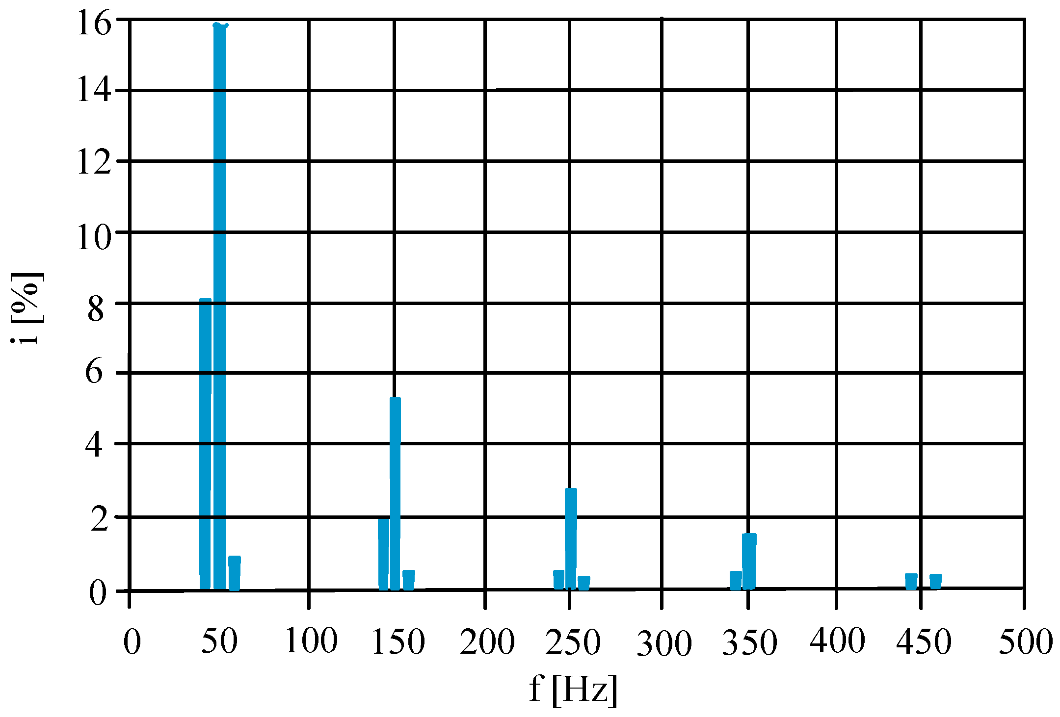
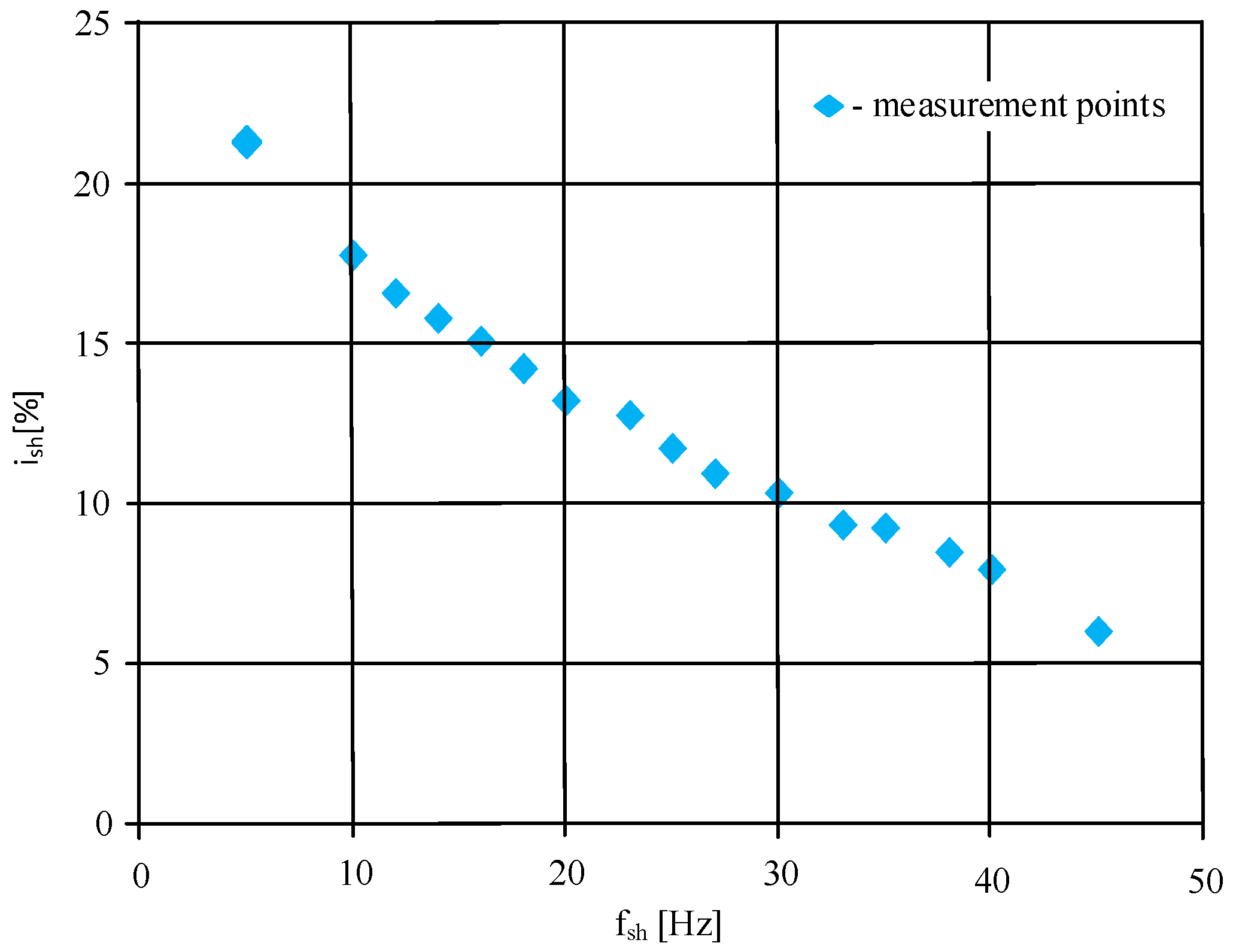
4.2. Effect of Negative Sequence Subharmonics on Currents

Noxious phenomena occurring in induction motors under VShs, such as vibration, torsional vibration, an increase in power losses, overheating and speed fluctuations [2,3,4,20,21,23,24,26,27,28,29,30,31,33,34,35] are generally interconnected with current subharmonics and interharmonics flowing through windings.
Below, Figure 3 and Figure 4 present a comparison of current spectra for motor 1 supplied with the voltage containing VShs of frequency fsh = 43 Hz and different sequences. For the injection of a positive sequence voltage subharmonic (Figure 3), the current contains, among others, a subharmonic with a value equal to 12.6% of the rated current, accompanied by the current interharmonic with a value that is 10.6% of Irat and frequency 57 Hz. The presence of current interharmonic results from the speed fluctuations and resonance phenomena [24,31,33]. Further, for the injection of a negative sequence voltage subharmonic (Figure 4), the current subharmonic is equal 8.3% of Irat and the 57-Hz current interharmonic, which is merely 0.9% of Irat. It is worth adding that the presence of the third harmonic in the phase stator winding current is typical for delta-connected motors.
The difference between the effects of a positive and negative sequence VShs results mostly from the frequency of torque pulsations (fp). For positive sequence VShs, the magnetic fields induced by the fundamental and subharmonic components rotate in the same direction, and the frequency of the torque pulsations is (based on [24]):
f p = f 1 f s h
For negative sequence VShs they rotate in the opposite direction and the frequency of torque pulsations is equal:
f p = f 1 + f s h
In practice, for positive sequence VShs, the frequency fp is within the range 0–f1, while for negative sequence subharmonics, it is within the range f1–2f1. At the same time, for the frequency of torque pulsations fp close to the natural frequency of the rigid-body mode (fNr-b) [18], resonance may occur [2,18,31,33]). The frequency fNr-b is in the single-tens-of-Hz range for small motors, while for powerful ones, it is a few Hz (based on the authors’ experience [2,18,31,32,33]). Under the rigid-body resonance, the speed fluctuations boost current subharmonics and interharmonics, which results in a further magnification of torque pulsations and speed fluctuations. Consequently, current subharmonics and interharmonics may reach extremely high values [2,33]. Such resonance phenomena were reported for both asynchronous and synchronous motors under positive sequence VShs [2,18,23,31,33], whereas for negative sequence VShs, they are not expected. Another difference between positive and negative sequence VShs concerns the slip. For positive sequence VShs, it is less than zero, and for negative sequence VShs, it is always greater than two (for perfect idling).
In Figure 5, the current subharmonics versus the frequency of negative sequence VShs are presented. For motor 1, the current subharmonics are as high as 32.9% of Irat for a frequency of fsh = 10 Hz, whereas for greater frequencies fsh they are much lower. The shape of this characteristic can be explained by the fact that low-frequency current subharmonics are suppressed mostly by windings resistance, which takes a comparatively low value for medium- and high-power induction motors (based on [31]). Further, for motor 2, the current subharmonics are significantly lower and change approximately linearly from 11.5% of Irat for fsh = 10 Hz to 7.0% of Irat for fsh = 45 Hz. For comparison, for positive sequence VShs and the work with the high moment of load inertia, the current subharmonic is about 30% higher for fsh = 10 Hz and much lower for fsh = 45 Hz.
It should be added that the authors also carried out numerical investigations for various moments of load inertia as well for the work with a constant rotational speed, which corresponds to the work with a load of the high moment of inertia [31]. The results of the calculations show that for negative sequence VShs, the moment of load inertia has a negligible impact on current subharmonics and interharmonics. On the contrary, their values significantly depend on the moment of load inertia for positive sequence VShs [31,33].
In summary, for negative sequence VShs, current subharmonics practically do not depend on the moment of load inertia, and in some cases, are significantly less than for positive sequence VShs. The differences result mostly from other frequencies of torque pulsations and the absence of the rigid-body mode resonance for negative sequence VShs.

4.3. Torque Pulsations under Negative Sequence Subharmonics

Torque pulsations induce vibrations [43,44], which may reach an extraordinary level under VShs [2]. To make the matter worse, under the elastic-mode resonance, the amplitude of torque pulsations could be significantly magnified, which may lead to a mechanical failure of a power train [21,31].
Below, in Figure 6, the pulsating torque component (ΔTp) caused by VShs is presented. In practice, the characteristics shown in Figure 6 correspond to the torque component of the frequency described with Equation (8). For motor 1 and the frequency fsh = 10 Hz, the component ΔTp is 41% of Trat. With the increasing frequency fsh, the pulsating torque component decreases nonlinearly to about 10% of Trat for fsh = 45 Hz. Further, for motor 2, the component ΔTp (Figure 6) is much less affected by fsh than in the case of motor 1 and takes significantly lower values (between 8.6% and 15.7% of Trat).
As mentioned in the previous subsection, the resonance of the rigid-body mode was not observed under negative sequence VShs. At the same time, resonance phenomena reported under positive sequence VShs [23,31,33] may significantly increase the value of the torque component ΔTp. For example, for motor 2 under the resonance, the pulsating torque component was about 60% of Trat.
It is also worth adding that the FEM analyses on torque pulsations were carried out for a constant rotational speed. The differences between the torque pulsations for the constant rotational speed and a load of the negligible moment of inertia are inconsiderable, similar to the case of currents (see the previous subsection).
In summary, the torque pulsations caused by negative sequence VShs may take significant values, up to about 40% of Trat in the case of the investigated motors. The main difference between the effect of negative and positive sequence VShs is the lack of resonance phenomena (of the rigid-body mode) for negative sequence VShs.

4.4. Vibration under Negative Sequence Subharmonics

The results of the empirical investigations on vibration are presented below. As the highest vibration under VShs occurs for an idling motor (for example [2,32]), the experimental research concerned no-load. The appropriate tests were performed for motor 3, Case A (an uncoupled motor) and Case B (a motor coupled with a DC generator)—see Section 3. All the presented measurement points correspond to the averaged value vibration velocity obtained in three independent tests. The averaging was performed directly in the BK Connect software. Further, the assessment of vibration severity was carried out in accordance with the standard [45] because the threshold values of evaluation zones [41,45] are not univocally specified in its current version [41].
The measured broad-band vibration velocity [41,45] is shown in Figure 7 and Figure 8 for Case A and Case B, respectively. For Case A, the maximal velocity is 4.46 mm/s for frequency fsh = 16 Hz and the vertical direction. For Case B (Figure 8), the maximal vibration velocity is 4.23 mm/s for frequency fsh = 20 Hz and the longitudinal direction. Notably, for electrical machines under power quality disturbances, the most severe vibration is often observed in the transverse direction [2,43,44], but it also may occur in the longitudinal direction [32,43].
For both Case A and Case B, the measured vibration velocity generally falls into the evaluation Zone C [41,45], which corresponds to the vibration velocity within the range 1.8–4.5 mm/s for small electric motors [45]. It should be stressed that vibration within Zone C is considered unacceptable for long-term continuous operation [41,45]. Additionally, for Case A (Figure 7), the maximal vibration velocity (4.46 mm/s) is close to the threshold value of the evaluation Zone D (4.5 mm/s) [45]. According to the standards [41,45], the vibration within Zone D is “normally considered to be of sufficient severity to cause damage to the machine”.
Although the measured vibration velocity should be considered excessive, it was significantly less than for the same motor under positive sequence VShs [2]. For a positive sequence and Case A, the vibration velocity was as high as 7.38 mm/s and for Case B, it was 6.95 mm/s. The details concerning the investigations under positive sequence VShs are presented in the authors’ previous study [2]. The difference between the effect of positive and negative sequence VShs can be explained by two reasons. The first is the lack of the rigid-body resonance for negative sequence subharmonics, which can significantly amplify torque pulsations (see the previous subsections). The other reason could be a different response of the mechanical structure to torque pulsations of various frequencies [43,44]. As mentioned above, for positive and negative sequence VShs, torque pulsations are of different frequencies.
It is also worth adding that for Case A and positive sequence VShs, the maxima of the current subharmonic and vibration velocity occur for the same frequency corresponding to the rigid-body resonance [2]. In contrast, for negative sequence VShs, the characteristics of vibration velocity (Figure 7) and current subharmonics (Figure 9) differ significantly.
In summary, negative sequence VShs may cause excessive vibration. However, in the case of the investigated motor, the vibration levels are significantly lower than under a positive sequence VShs.

5. Discussion

The previous works [2,3,4,20,21,23,24,26,27,28,29,30,31,33,34,35] show the extraordinarily harmful impact of VShs (voltage subharmonics) on induction motors. These analyses were generally limited to positive sequence VShs; however, in power network subharmonics, both sequences may occur. In this study the effect of negative sequence VShs on induction motors was examined.
The negative sequence VShs may cause a flow of current subharmonics of significant values, high torque pulsations and excessive vibration, similar to the effects of positive sequence VShs. Nevertheless, there are some differences between the effects of positive and negative sequence VShs on induction motors. As discussed in the previous section, the differences generally result from the frequency of torque pulsations fp. For positive sequence subharmonics, the frequency fp is between null and the line frequency, whereas for the negative sequence, it is between the line and twice the line frequency. For negative sequence VShs, the frequency fp is usually considerably greater than the natural frequency fNr-b (see Section 3), and the resonance of the rigid-body mode does not occur. Consequently, torque pulsations, the vibration velocity and an increase in windings temperature [33,35] might be remarkably less than for the same motors under positive sequence VShs. Further, for positive sequence VShs, current subharmonics and torque pulsations depend significantly on the moment of load inertia [23,31,33], whereas for negative sequence they are practically independent.
Apart from of the rigid-body mode resonance of the rotating mass, other kinds of resonances might also occur, leading to excessive vibration or torsional vibration. It should be stressed that “excessive motor electromagnetic vibration is very often a result of a resonance condition on the structure of an entire unit or on the motor components, such as a stator core or frame” [43]. Further, as mentioned in Section 1, the elastic-mode resonance of the rotating mass is particularly dangerous for a power train structure [21,36]. Resonance phenomena could magnify the amplitude of torque pulsations, even by a factor exceeding 100 [21], leading to a shaft or coupling destruction [21,31]. For some power trains, the natural frequency of the first elastic mode is below the line frequency (especially for high power motors), and for others, it is above (based on [21,31,36] and the authors’ calculations). The former might be exposed to the resonance under positive sequence VShs, and the latter under negative sequence VShs. As a result, a power train resistant to positive sequence VShs could be particularly susceptible to negative sequence VSs of the same frequency and vice versa.
In summary, for the investigated motors, negative sequence VShs caused significantly lower torque pulsations and vibration than positive sequence VShs. On the other hand, the appearance of negative sequence VShs carries the additional risk of damage to the power train because of possible resonance phenomena.

6. Conclusions

In a power network, both a positive and negative sequence voltage subharmonic (VShs) could be expected. The sequence of VShs is not connected with their frequency, as in the case of harmonics, but with their origin [16]. The results of investigations presented here show that negative sequence VShs may cause a flow of significant current subharmonics, high torque pulsations and vibration at an unacceptable level. Notably, for the investigated motors, the intensity of these undesirable phenomena was usually considerably less than for positive sequence VShs. For negative sequence VShs, the rigid-body mode resonance of the rotating mass is not expected, current subharmonics and torque pulsations are practically independent of the moment of load inertia, contrary to positive sequence VShs [31]. The differences between positive and negative sequence VShs result chiefly from another frequency of torque pulsations. For a positive sequence, it is between null and the line frequency, and for a negative sequence, it is between the line frequency and the double line frequency. Due to another frequency of torque pulsations, negative sequence subharmonics might cause various resonance phenomena in motors that are comparatively resistant to positive sequence VShs. In particular, the occurrence of the elastic-mode resonance of the rotating mass [21,31,36] can result in the destruction of a power train.

Author Contributions

Conceptualization, P.G., M.P.; methodology, D.H., P.K. and M.P.; formal analysis, D.H., P.K., A.M. and M.P.; investigation D.H., P.K., A.M. and M.P.; writing—original draft preparation, P.G.; supervision, P.G. All authors have read and agreed to the published version of the manuscript.

Funding

This project is financially supported under the framework of a program of the Ministry of Science and Higher Education (Poland) as “Regional Excellence Initiative” in the years 2019–2022, project number 006/RID/2018/19, amount of funding 11,870,000 PLN.

Data Availability Statement

Not applicable.

Conflicts of Interest

The authors declare no conflict of interest. The funders had no role in the design of the study; in the collection, analyses, or interpretation of data; in the writing of the manuscript, or in the decision to publish the results.

References

  1. Crotti, G.; D’Avanzo, G.; Letizia, P.S.; Luiso, M. Measuring harmonics with inductive voltage transformers in presence of subharmonics. IEEE Trans. Instrum. Meas. 2021, 70, 1–13. [Google Scholar] [CrossRef]
  2. Gnaciński, P.; Pepliński, M.; Murawski, L.; Szeleziński, A. Vibration of induction machine supplied with voltage containing subharmonics and interharmonics. IEEE Trans. Energy Convers. 2019, 34, 1928–1937. [Google Scholar] [CrossRef]
  3. Testa, A.; Langella, R. Power system subharmonics. In Proceedings of the IEEE Power Engineering Society General Meeting, San Francisco, CA, USA, 16–16 June 2005; Volume 3, pp. 2237–2242. [Google Scholar]
  4. Zhang, S.; Kang, J.; Yuan, J. Analysis and suppression of oscillation in V/F controlled induction motor drive systems. IEEE Trans. Transp. Electrif. 2022, 8, 1566–1574. [Google Scholar] [CrossRef]
  5. Bollen, M.H.J.; Gu, I.Y.H. Origin of power quality variations. In Signal Processing of Power Quality Disturbances; Wiley: New York, NY, USA, 2006; pp. 41–162. [Google Scholar]
  6. Wen, Z.; Peng, S.; Yang, J.; Deng, J.; He, H.; Wang, T. Analysis of the propagation characteristic of subsynchronousoscillationin wind integrated power system. Energies 2019, 12, 1081. [Google Scholar] [CrossRef] [Green Version]
  7. Xie, G.-L.; Zhang, B.-H.; Li, Y.; Mao, C.-X. Harmonic propagation and interaction evaluation between small-scale wind farms and nonlinear loads. Energies 2013, 6, 3297–3322. [Google Scholar] [CrossRef] [Green Version]
  8. Xie, X.; Zhang, X.; Liu, H.; Liu, H.; Li, Y.; Zhang, C. Characteristic analysis of subsynchronous resonance in practical wind farms connected to series-compensated transmissions. IEEE Trans. Energy Convers. 2017, 32, 1117–1126. [Google Scholar] [CrossRef]
  9. Pan, Y.; Sangwongwanich, A.; Yang, Y.; Blaabjerg, F.A. Phase-shifting MPPT method to mitigate interharmonics from cascaded H-bridge PV inverters. In Proceedings of the 2020 IEEE Applied Power Electronics Conference and Exposition (APEC), New Orleans, LA, USA, 15–19 March 2020; pp. 157–163. [Google Scholar]
  10. Ravindran, V.; Busatto, T.; Rönnberg, S.K.; Meyer, J.; Bollen, M.H.J. Time-varying interharmonics in different types of grid-tied PV inverter systems. IEEE Trans. Power Deliv. 2020, 35, 483–496. [Google Scholar] [CrossRef]
  11. Zhong, Q.; Qiu, Y.; Zhao, Y.; Li, H.; Wang, G.; Wen, F. Interharmonic Analysis Model of Photovoltaic Grid-connected System with Extended Dynamic Phasors. J. Mod. Power Syst. Clean Energy 2021, 9, 1540–1547. [Google Scholar] [CrossRef]
  12. Li, M.; Wang, X.; Tan, J. The analysis of interharmonics generated by VSI-fed adjustable speed drives considering mechanical load fluctuations. In Proceedings of the 2012 Power Engineering and Automation Conference, Wuhan, China, 18–20 September 2012; pp. 1–5. [Google Scholar]
  13. Nassif, A.B. Assessing the impact of harmonics and interharmonics of top and mudpump variable frequency drives in drilling rigs. IEEE Trans. Ind. Appl. 2019, 55, 5574–5583. [Google Scholar] [CrossRef]
  14. Soltani, H.; Davari, P.; Zare, F.; Blaabjerg, F. Effects of modulation techniques on the input current interharmonics of adjustable speed drives. IEEE Trans. Ind. Electron. 2018, 65, 167–178. [Google Scholar] [CrossRef]
  15. Testa, A.; Akram, M.F.; Burch, R.; Carpinelli, G.; Chang, G.; Dinavahi, V.; Hatziadoniu, C.; Grady, W.M.; Gunther, E.; Halpin, M.; et al. Interharmonics: Theory and modeling. IEEE Trans. Power Deliv. 2007, 22, 2335–2348. [Google Scholar] [CrossRef]
  16. Zhang, D.; Xu, W.; Liu, Y. On the phase sequence characteristics of interharmonics. IEEE Trans. Power Deliv. 2005, 20, 2563–2569. [Google Scholar] [CrossRef]
  17. Lin, F.; Lin, Y.; Huang, D.; Lin, C.; Zhang, Y. Ultra-High-Power Arc Furnace Model for Low Frequency Non-Stationary Inter-harmonics. In Proceedings of the 2020 5th Asia Conference on Power and Electrical Engineering (ACPEE), Chengdu, China, 4–7 June 2020; pp. 2049–2053. [Google Scholar]
  18. Arkkio, A.; Mölsä, E.; Holopainen, T.P. Reducing the losses of electrical machines under torsional vibration. In Proceedings of the 2018 XIII International Conferenceon Electrical Machines (ICEM), Alexandroupoli, Greece, 3–6 September 2018; pp. 1303–1309. [Google Scholar]
  19. Zhiyuan, M.; Xiong, M.W.; Le, L.; Zhong, X. Interharmonics analysis of a 7.5 kW air compressor motor. CIRED Open Access Proc. J. 2017, 2017, 738–741. [Google Scholar] [CrossRef] [Green Version]
  20. Jardan, R.K.; Stumpf, P.; Bartal, P.; Varga, Z.; Nagy, I. A novel approach in studying the effects of subharmonics on ultrahigh-speed ac motor drives. IEEE Trans. Ind. Electron. 2010, 58, 1274–1281. [Google Scholar] [CrossRef]
  21. Tripp, H.; Kim, D.; Whitney, R. A comprehensive cause analysis of a coupling failure induced by torsional oscillations in a variable speed motor. In Proceedings of the 22nd Turbomachinery Symposium, College Station, TX, USA; 1993; pp. 17–24. [Google Scholar]
  22. Gallo, D.; Landi, C.; Langella, R.A.; Testa, A. Limits for low frequency interharmonic voltages: Can they be based on the flickermeter use. In Proceedings of the 2005 IEEE Russia Power Tech, St. Petersburg, Russia, 27–30 June 2005; pp. 1–7. [Google Scholar]
  23. Ghaseminezhad, M.; Doroudi, A.; Hosseinian, S.H.; Jalilian, A. High torque and excessive vibration on the induction motors under special voltage fluctuation conditions. COMPEL-Int. J. Comput. Math. Electr. Electron. Eng. 2021, 40, 822–836. [Google Scholar] [CrossRef]
  24. Tennakoon, S.; Perera, S.; Robinson, D. Flicker attenuation—Part I: Response of three-phase induction motors to regular voltage fluctuations. IEEE Trans. Power Deliv. 2008, 23, 1207–1214. [Google Scholar] [CrossRef]
  25. Barros, J.; de Apraiz, M.; Diego, R.I. Measurement of subharmonics in power voltages. In Proceedings of the Power Tech 2007 IEEE Conference, Lausanne, Switzerland, 1–5 July 2007; pp. 1736–1740. [Google Scholar]
  26. De Abreu, J.P.G.; Emanuel, A.E. Induction motor thermal aging caused by voltage distortion and imbalance: Loss of useful life and its estimated costs. IEEE Trans. Ind. Appl. 2002, 38, 12–20. [Google Scholar] [CrossRef]
  27. Farah M., J.; Abdollahi, R. An analytical investigation of induction motor behavior in the case of flicker occurrence using finite element method. Univ. Politeh. Buchar. Sci. Bull. Ser. C-Electr. Eng. Comput. Sci. 2019, 81, 181–192. [Google Scholar]
  28. Ghaseminezhad, M.; Doroudi, A.; Hosseinian, S.H.; Jalilian, A. Analysis of voltage fluctuation impact on induction motors by an innovative equivalent circuit considering the speed changes. IET Gener. Transm. Distrib. 2017, 11, 512–519. [Google Scholar] [CrossRef]
  29. Ghaseminezhad, M.; Doroudi, A.; Hosseinian, S.H.; Jalilian, A. Analytical field study on induction motors under fluctuated voltages. Iran. J. Electr. Electron. Eng. 2021, 17, 1620. [Google Scholar]
  30. Ghaseminezhad, M.; Doroudi, A.; Hosseinian, S.H.; Jalilian, A. An investigation of induction motor saturation under voltage fluctuation conditions. J. Magn. 2017, 22, 306–314. [Google Scholar] [CrossRef]
  31. Gnaciński, P.; Klimczak, P. High-Power induction motors supplied with voltage containing subharmonics. Energies 2020, 13, 5894. [Google Scholar] [CrossRef]
  32. Gnaciński, P.; Muc, A.; Pepliński, M. Influence of Voltage Subharmonics on Line Start Permanent Magnet Synchronous Motor. IEEE Access 2021, 9, 164275–164281. [Google Scholar] [CrossRef]
  33. Gnaciński, P.; Pepliński, M.; Hallmann, D.; Jankowski, P. The effects of voltage subharmonics on cage induction machine. Int. J. Electr. Power Energy Syst. 2019, 111, 125–131. [Google Scholar] [CrossRef]
  34. Gnaciński, P.; Pepliński, M.; Hallmann, D.; Jankowski, P. Induction cage machine thermal transients under lowered voltage quality. IET Electr. Power Appl. 2019, 13, 479–486. [Google Scholar] [CrossRef]
  35. Gnaciński, P.; Pepliński, M. Heating of induction cage machine supplied with voltage containing negative-sequence subharmonics. In Proceedings of the 2016 XXII International Conference on Electrical Machines (ICEM), Lausanne, Switzerland, 4–7 September 2016; pp. 1770–1775. [Google Scholar]
  36. Feese, T.; Ryan, M. Torsional vibration problem with motor/ID fan system due to PWM variable frequency drive. In Proceedings of the 37th Turbomachinery Symposium, Houston, TX, USA, 8–11 September 2008. [Google Scholar]
  37. EN Standard 50160; Voltage Characteristics of Electricity Supplied by Public Distribution Network. CELENEC: Brussels, Belgium, 2010.
  38. IEEE Standard 519-2014 (Revision of IEEE Standard 519-1992); IEEE Recommended Practice and Requirements for Harmonic Control in Electric Power Systems. IEEE: New York, NY, USA, 2014.
  39. Kuwałek, P.; Wiczyński, G. Dependence of Voltage Fluctuation Severity on Clipped Sinewave Distortion of Voltage. IEEE Trans. Instrum. Meas. 2021, 70, 1–8. [Google Scholar] [CrossRef]
  40. Ho, S.L.; Fu, W.N. Analysis of indirect temperature-rise tests of induction machines using time stepping finite element method. IEEE Trans. Energy Convers. 2001, 16, 55–60. [Google Scholar] [CrossRef] [Green Version]
  41. ISO Standard 20816-1; Mechanical Vibration—Measurement and Evaluation of Machine Vibration—Part 1: General Guidelines. ISO: Genova, Switzerland, 2016.
  42. Tarasiuk, T. Estimator-analyzer of power quality: Part I–Methods and algorithms. Meas. J. Int. Meas. Confed. 2011, 44, 238–247. [Google Scholar] [CrossRef]
  43. Tsypkin, M. Induction motor condition monitoring: Vibration analysis technique—diagnosis of electromagnetic anomalies. In Proceedings of the 2017 IEEE International Automatic Testing Conference, Schaumburg, IL, USA, 9–15 September 2017. [Google Scholar]
  44. Tsypkin, M. The origin of the electromagnetic vibration of induction motors operating in modern industry: Practical experience—Analysis and diagnostics. IEEE Trans. Ind. Appl. 2017, 53, 1669–1676. [Google Scholar] [CrossRef]
  45. ISO Standard 10816-1; Mechanical Vibration—Evaluation of Machine Vibration by Measurements on Non-Rotating Parts—Part 1: General Guidelines. ISO: Genova, Switzerland, 1995.
Figure 1. Simplified diagram of the measurement stand.
Energies 15 08797 g001
Figure 2. Measured and calculated current subharmonics (related to the rated current) vs. the frequency of voltage subharmonics for motor 2 and voltage containing negative sequence subharmonics of the value Ush = 1% U1.
Energies 15 08797 g002
Figure 3. Current spectrum of motor 1 supplied with the voltage containing the positive sequence subharmonic of frequency fsh = 43 Hz.
Energies 15 08797 g003
Figure 4. Current spectrum of motor 1 supplied with the voltage containing the negative sequence subharmonic of frequency fsh = 43 Hz.
Energies 15 08797 g004
Figure 5. Current subharmonics vs. the subharmonic frequency for motor 1 and motor 2.
Energies 15 08797 g005
Figure 6. Pulsating torque component ΔTp of the frequency described with Equation (8) vs. the subharmonic frequency for motor 1 and motor 2.
Energies 15 08797 g006
Figure 7. Measured broad-band vibration velocity in the horizontal (H), vertical (V) and longitudinal (L) direction vs. the subharmonic frequency for motor 3 Case A (uncoupled motor).
Energies 15 08797 g007
Figure 8. Measured broad-band vibration velocity in the horizontal (H), vertical (V) and longitudinal (L) direction vs. the subharmonic frequency for motor 3 Case B (a motor coupled with a DC generator).
Energies 15 08797 g008
Figure 9. Measured current subharmonics vs. the subharmonic frequency for motor 3 Case A.
Energies 15 08797 g009
Table 1. Chosen parameters of the investigated motors.
MotorTypeRated Power
(kW)
Rated Speed
(rpm)
Rated
Voltage
(V)
Rated
Current
(A)
motor 1SLgm 315 ML2B2002982400 Δ346
motor 2TSg100L-4B31420380 Δ6.9
motor 33SIE100L4B31465400 Y6.3
Publisher’s Note: MDPI stays neutral with regard to jurisdictional claims in published maps and institutional affiliations.

