Article

Thermal Visualization and Performance Analysis in a Channel Installing Transverse Baffles with Square Wings

1
Division of System Engineering, Graduate School of Engineering, Mie University, Tsu 514-8507, Japan
2
Department of Mechanical Engineering, Mahanakorn University of Technology, Bangkok 10530, Thailand
3
School of Engineering, King Mongkut’s Institute of Technology Ladkrabang, Bangkok 10520, Thailand
4
Division of Mechanical Engineering, Graduate School of Engineering, Mie University, Tsu 514-8507, Japan
5
Engineering Innovation Unit, Graduate School of Regional Innovation Studies, Mie University, Tsu 514-8507, Japan
*
Author to whom correspondence should be addressed.
Energies 2022, 15(22), 8736; https://doi.org/10.3390/en15228736
Submission received: 13 October 2022 / Revised: 10 November 2022 / Accepted: 13 November 2022 / Published: 20 November 2022
(This article belongs to the Special Issue New Challenges in Heat Transfer Enhancement)

Abstract

:
The experimental examination of local heat transfer, thermal intensification, friction factors, and thermal performance factors (TPF) in a rectangular channel with square-winged transverse baffles (SW-TB) are presented in this paper. The purpose of this study is to modify the typical transverse baffles (TB) into square-winged transverse baffles (SW-TB) in order to improve the thermal performance and heat transfer rate of the channel. The effects of SW-TBs with various wing attack angles and Reynolds numbers on the heat transfer performance characteristics were examined using a thermochromic liquid crystal sheet. In the experiments, the SW-TBs were attached to the bottom wall of the channel, which had an aspect ratio (W:H) of 3.75:1. The SW-TBs had a width (w) of 150 mm, a square perforated cross-sectional area (a × b) of 8 × 8 mm2, and attack angles (θ) of 0° (solid transverse-baffle), 22.5°, 45°, 67.5°, and 90°. The bottom wall of the channel was evenly heated, while the other walls were insulated. The temperature contours on the heated surface were plotted using temperatures obtained through using the thermochromic liquid crystal (TLC) image-processing method. Experimental results revealed that the SW-TBs created multiple impinging jets, apart from the recirculation. At the proper attack angles (θ = 22.5° and 45°), the SW-TBs offered greater heat transfer rates and caused lower friction losses, resulting in higher TPFs than the solid transverse baffles. In the current work, channels where the SW-TBs display a θ = 45° presented the greatest TPF, as high as 1.26. The multiple impinging jets issuing by the SW-TBs suppressed the size of the recirculation flow and allowed better contact between the fluid flow and channel wall.

Graphical Abstract

1. Introduction

For more than a century, fluid mechanics and thermodynamics have been developing strategies to increase heat transfer in industrial/thermal-engineering applications [1]. Highly efficient heat exchangers are desired in thermal/energy engineering applications such as for solar air heating, refrigeration, gas turbines, vehicle manufacturing, and chemical engineering. This is to utilize energy resources efficiently and reduce costs. Several heat transfer devices have been developed to boost the rate of heat transfer. Baffles are common devices applied to intensify the heat transfer rates in channels, especially in solar air heaters. These devices promote axial-to-wall flow by cross-sectional mixing, intensification of flow turbulence, and flow collision near walls. Baffles of various designs, such as W-shaped baffles, perforated baffles, Z-shaped baffles, wavy surfaces [2], V-shaped baffles [3], baffles with wings, and arc-shaped baffles [4], among other types, have been proposed. The effects of baffles on thermal intensification, friction factors, and thermal performance factor (TPF) behaviors in flowing channels/ducts have been widely studied. Several parameters, such as pitch length, baffle height, attack angle, and Reynolds number [5,6], have been investigated. Karwa and Maheshwari [7] reported on the influence of fully and half-perforated baffles (open areas of 46% and 26%) on the TPF parameters in a channel, with the relative roughness pitches ranging from 7.2 to 28.8. Fully and half-perforated baffles (PBs) were installed at wider walls under constant rate heating conditions, with Reynolds numbers ranging from 2700 to 11,150. They discovered that the fully perforated and half-perforated baffles augmented the heat transfer rates by 169% and 274%, respectively, over that of a plain channel. However, the friction factors rose by 8.02 and 17.5 times, respectively. They also discovered that half-perforated baffles outperformed completely perforated baffles in terms of TPF. Half-perforated baffles achieved a 75% TPF advantage over a plain channel.
The influence of the inclined perforated baffles on the heat transfer rate, flow structure, and thermal performance in a flow channel was explored by Ary et al. [8]. Their results suggested that the flow structure around the holes varied substantially, depending on the number of holes, which had a significant impact on local heat transfer. Additionally, two baffles performed better than one. Sriromreun et al. [9] examined the influence of Z-shaped baffles having various baffle heights (e/H), pitch ratios (P/H), and arrangements in the Reynolds number range of 4400 to 20,400. They found that in-phase 45° Z-baffles yielded a greater heat transfer and TPF values than out-phase 45° Z-baffles. Kumar et al. [10] investigated heat transfer in a duct with periodic oblique baffles and perforated slots. They reported that the heat transfer rate increased to 9.0 times that of a plain channel. Additionally, thermal performance factors were enhanced to 3.4. Habet et al. [11] measured the heat transfer rates in a rectangular duct, with the inline and staggered baffles having perforation ratios (β) ranging from 0% (solid baffle) to 40%. At perforation ratios of 20% and 40%, staggered baffles performed better than the inline ones in terms of the heat transmission rate. They also discovered that, at a Reynolds number of 12,000, staggered baffles with β = 0% and solid baffles yielded the greatest thermal performance factor. Boonloi and Jedsadaratanachai [12] reported on the influence of wavy baffle turbulators, with wavy baffle height ratios (b/H) ranging from 0.05 to 0.3, on flow and heat transfer behaviors. Under optimal conditions, baffles having b/H = 0.1 gave the maximum thermal performance factor, 3.7. Bhattacharyya et al. [13] employed perforated angular-cut baffles with various pitch ratios, perforation ratios, attack angles, and configurations (inline/alternate) for heat transfer augmentation. Heat transfer was clearly more efficient at larger attack angles. Modified baffles with a perforation ratio of 0.15, pitch ratio of 0.1, and attack angle of 45° offered the greatest heat transfer. Faujdar et al. [14] analyzed the influence of V-down pattern perforated baffles with various baffle heights and open area ratios on the thermal performance of a solar air heater (SAH). A maximal thermal performance of 2.54 was achieved at a baffle height of 9 mm and a 20% open area. Tandel et al. [15] applied vertical plate perforated baffles in a SAH. They reported that the heat transfer coefficient and heat transfer rate were, respectively, 5.8% and 5.2% higher than a typical SAH. Recently, Khanlari et al. [16] reported that applying a CuO nano-embedded coating on SAH surfaces helped improve their energy and exergy efficiencies. El Habet et al. [17] investigated the effects of tilt angle (0°, 30°, 45°, and 60°) and the perforation ratio (10% to 40%) of staggered baffles on heat transfer and flow behaviors. Their results revealed that heat transfer and friction were higher at smaller tilt angles and perforation ratios. However, the maximum thermal enhancement ratio (optimal condition) was found at the largest tilt angle, 60°, and the smallest perforation ratio, 10%.
Typical/conventional transverse baffles (TB) are used to generate recirculation flow adjacent to the baffle rear, followed by reattachment, which helps to increase the heat transfer rate. However, the recirculation inefficiently transfers heat between the fluid flow and the local wall. The current work seeks ways to minimize the recirculation by forming a square wing to induce an impinging jet flow, attacking on the wall next to the rear, in order to improve heat transfer in the region. Several researchers attempted to modify baffles to enhance the heat transfer rate and reduce pressure losses. According to earlier research, holes and perforations in baffles (Figure 1) significantly help to reduce pressure losses. This idea has been adopted for newly designed baffles, namely, square-winged transverse baffles (SW-TBs). These transverse baffles with square wings are utilized to form (a) recirculation flow, which creates flow reattachment between the baffles; and (2) multiple impinging flows behind the baffles, to diminish the dead zone. The combination is expected to enhance the fluid–wall contact, and thus the heat transfer rate. In addition, the presence of gaps on the baffles also helps by reducing friction loss. This study encompasses assessing the different attack angles of the square wings (θ = 0° (solid transverse-baffle), 22.5°, 45°, 67.5°, and 90°), in order to find the optimum conditions for both heat transfer and friction loss. The novel contribution from this work is the visualization of the heat transfer behaviors by SW-TBs having different wing attack angles, using a thermochromic liquid crystal sheet. This technique gives the local thermal distributions on the wall surfaces, to gain a better understanding of the heat transfer enhancement mechanism and thus filling a gap in the current body of knowledge.

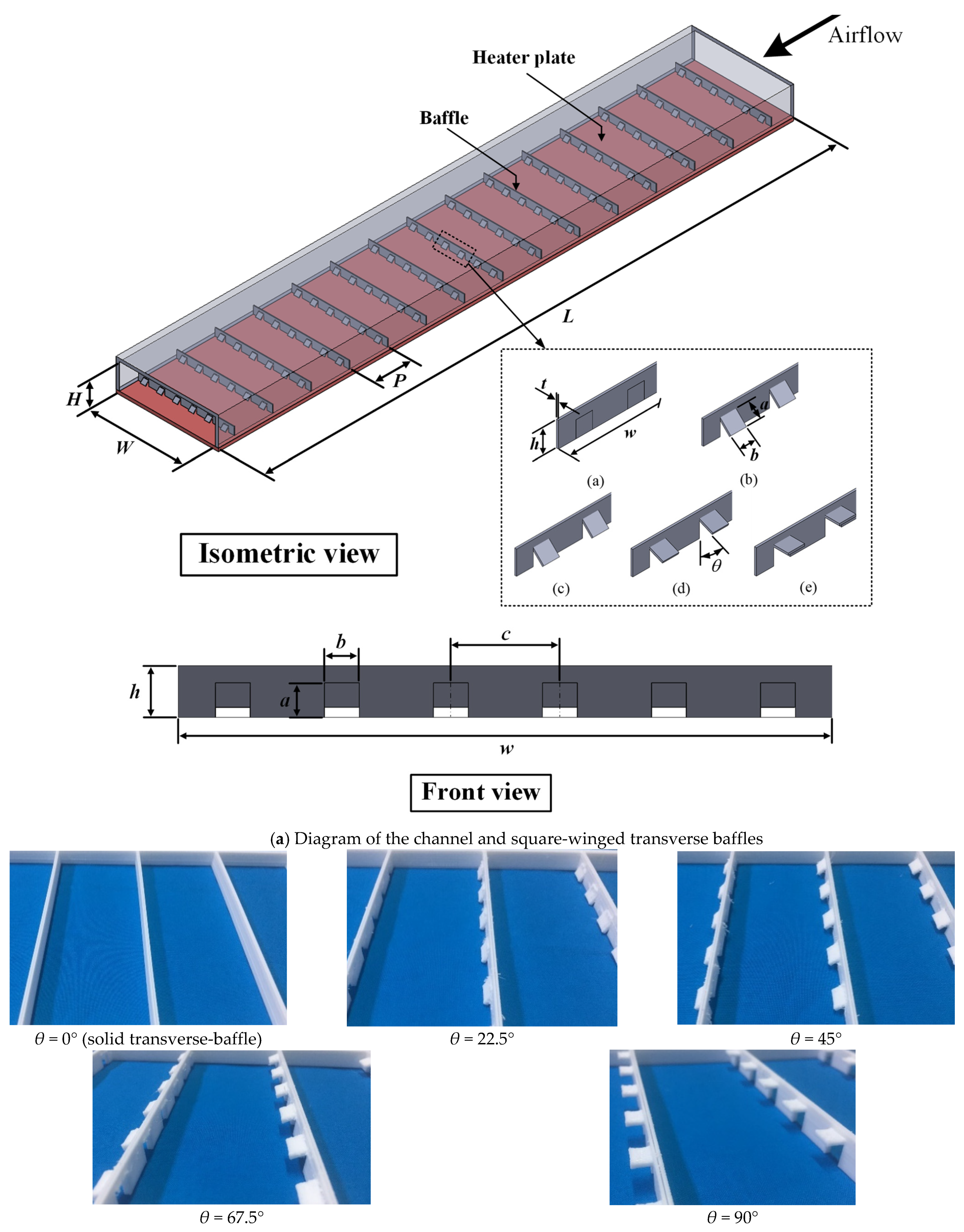
2. Channel and Perforated Square-Wing Transverse Baffle Configurations

In the present report, square-winged transverse baffles (SW-TBs) having various wing attack angles (θ) were tested in channel flow. Figure 2a,b show the channel and baffle features. A channel with a width (W) of 150 mm and height (H) of 40 mm (aspect ratio (AR) of 3.75:1) was constructed from acrylic plates. The total length of the channel was 3500 mm, which was divided into three sections. These sections were (1) a 2000 mm-long entrance section; (2) a 600 mm-long heating section; and (3) a 600 mm-long outlet section. Baffles were installed on the bottom wall of the channel. The SW-TB was made entirely of polylactic acid (PLA) plastic. The SW-TBs were 150 mm wide (W). The cross-sectional area of the perforated part was 8 × 8 mm2. Square-winged transverse baffles (SW-TBs) were fabricated with wing attack angles (θ) of 0° (solid transverse-baffle), 22.5°, 45°, 67.5°, and 90°. The SW-TBs were installed with a constant pitch length (p) of 60 mm or a pitch ratio (p/H) of 1.5 (60 mm). During experiments, the bottom wall was heated using a thin heater sheet (0.254 mm) under a constant heat flux condition of 600 W/m2, while the other three walls were insulated.

3. Experimental Program

Figure 2c depicts the experimental facilities used in the current research. A flow channel with square-winged transverse baffles (SW-TBs), an orifice flow meter with a control valve, a high-pressure blower, a data logger, resistance temperature detectors (RTDs), a digital pressure gauge, an electric heater sheet, a digital multi-meter, a Variac transformer, and an inverter comprised the experimental setup. Voltage was regulated using a Variac transformer to control the heat flow via an electric heater sheet. Three RTDs were used to monitor the inlet air temperatures, and five RTDs were used to monitor the outlet air temperatures. A thermochromic liquid crystal (TLC) sheet was placed over the bottom wall of the channel to monitor the wall temperatures along the 150 × 600 mm2 test section. The heat transfer region was a bottom wall that was maintained under a steady heat flux condition. The heat transfer area was 150 mm wide and spanned between two baffle modules. The distance between the two baffle modules was 120 mm (2p/H). Throughout the test period, a constant 60 W of electrical power was supplied. To measure the temperature distribution on the heated surface, TLCs were fitted on the heated test surface. The TLCs utilized in this experiment are designed to operate in the temperature range of 30–35 °C. Image-processing software then performed analysis on the collected images. A calibrated orifice flow meter was used to monitor the air flow rates. Reynolds numbers were controlled over the range of 6000 to 24,000 by adjusting the volumetric air flow rate at the entrance using a control valve and a three-phase inverter. A digital pressure gauge was used to monitor the pressure losses (ΔP) over the test section using entrance and exit static pressure taps in the bottom wall of the channel. The opening area ratio (β) of the square-winged transverse baffles (SW-TBs) was determined in this study as the area ratio of the perforation holes to the SW-TB frontal area:
β = (n(ab))/(Wh)
where n is the number of perforation holes; a is the perforation width (8 mm); b is the perforation height (8 mm); W is the baffle width (150 mm); and h is the baffle height (12 mm). The opening area ratio (β) was kept constant at 0.21. The test conditions for the experiment are fully described in Table 1.

4. Data Assessment

This section provides a summary of the data reduction of the measured results. The Nusselt number, friction factor, and TPF for the channel containing SW-TBs are determined as follows. The convective heat transfer heat energy (Qconv) from the heater to the air in a channel (Qa) is
Q conv   =   Q a
In terms of enthalpy change [4,9], Qa may be written as
Q a   =   m ˙ c p , a ( T o T i )
A heat balance revealed that Qa was 6.5% less than the heat provided by the heater (QVI = IV).
The total input heat to the heating wire (QVI) can be calculated from the output voltage (V) and current (I) of the power supply. The heat loss can be examined from
( ( Q VI Q a ) / Q VI )   ×   100 %     6.5 %
The average value of heat transfer rate obtained by heat supplied by the electric heating wire (QVI) and that absorbed by the air in the test section is determined for the calculation of an internal convective heat transfer coefficient.
The heat transfer through the channel can be expressed as follows [4,9]:
Q conv   =   h A ( T ˜ w T b )
where A is the heat transfer area at the heated test channel (W × L = 150 mm × 120 mm). Bulk air temperature is determined as Tb = (To + Ti)/2 and T ˜ w is the average wall temperature. Substituting Equations (3) and (5) into Equation (2) yields [4,9]:
h   =   m ˙ c p , a ( T o T i ) / A ( T ˜ w T b )
Then, the local Nu Equation (5) can be evaluated from [4,9]:
N u   =   h D h / k f
The Friction factor (f) can be calculated from [4,9]:
f   =   ( 2 Δ P / L ) ( ρ u 2 D h )
The data are recorded after the system reaches a steady state. The Reynolds number (Re) is defined by [4,9]:
R e   =   ρ u D h / μ
where Dh is the tube hydraulic diameter; u is the inlet air velocity; and ρ and μ are the density and dynamic viscosity of air, respectively. In Equation (9), ρu is the mass flux, which is estimated as m ˙ / A i n , where Ain is the cross-sectional area of the channel entrance. Inlet temperature is used to calculate the kinematic viscosity (μ). Webb [18] introduced the concept of heat transfer augmentation or thermal performance factor (TPF), which is defined as the ratio of the heat transfer coefficient (h) of an enhanced channel to that of a smooth channel (hs) at constant pumping power.
Using the criterion of a constant pumping power evaluation [18]:
( V ˙ Δ P ) s   =   ( V ˙ Δ P )
The following can be provided as the link between the friction factor and Reynolds number:
(fRe3)s = (fRe3)
Res = Re(f/fs)1/3
Under the same pumping (pp) condition, the thermal performance factor (TPF) is evaluated by simultaneous determination of enhanced heat transfer and friction loss in terms of the Nusselt number ratio and friction factor ratio, respectively. The equation of TPF can be written as follows [4,9,18,19]:
TPF   =   h h s | p p   =   N u N u s | p p   =   ( N u N u s ) ( f s f ) 1 / 3
In the current study, the uncertainties of the key parameters were evaluated using Equations (14)–(18). The following equations were devised by Kline and McClintock [20] based on the errors of the individually observed parameters (x1, x2, … xn) to provide the uncertainties of the prediction parameter (X). The evaluated uncertainties are summarized in Table 2.
δ X X   =   ( δ x 1 x 1 ) 2 + ( δ x 2 x 2 ) 2 + + ( δ x n x n ) 2
Δ Re Re   =   ( Δ u u ) 2 + ( Δ μ μ ) 2 + ( Δ ρ ρ ) 2
Δ N u N u   =   ( Δ h h ) 2 + ( Δ k k ) 2
Δ f f   =   ( Δ ( Δ P ) Δ P ) 2 + ( Δ ρ ρ ) 2 + ( 2 Δ u u ) 2
Δ T P F T P F   =   1 3 ( 3 Δ N u N u ) 2 + ( 3 Δ N u p N u p ) 2 + ( Δ f f ) 2 + ( Δ f p f p ) 2

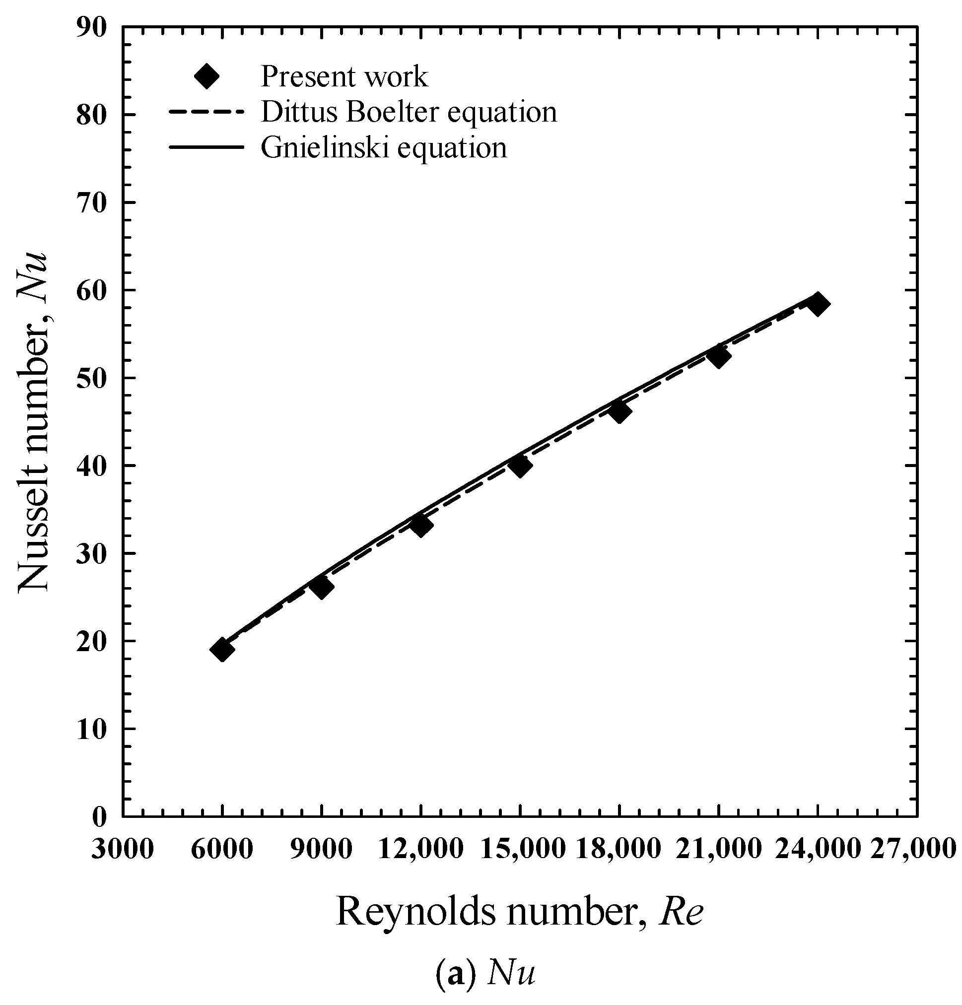
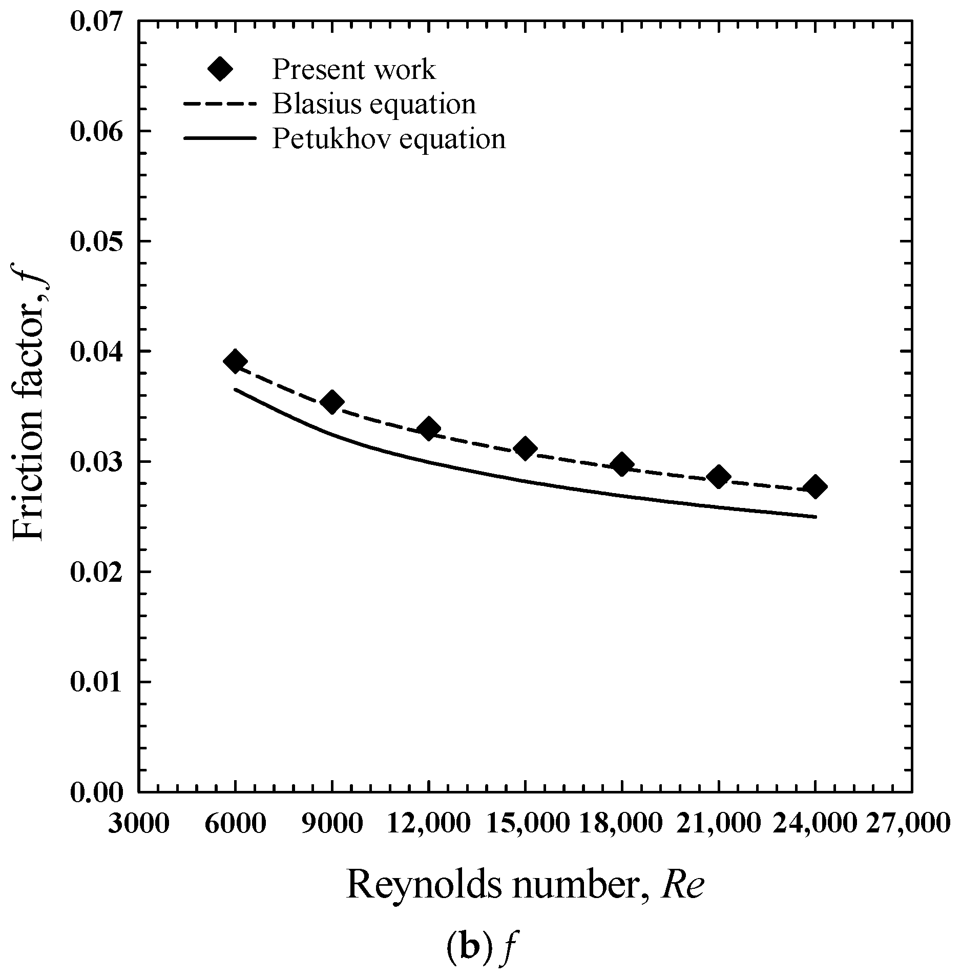
5. Experimental Validation

The Nu and f results of the current smooth channel were validated by comparing the experimental data with the results obtained from the standard correlations [21], as illustrated in Figure 3. This analysis shows the reliability of the experimental system. Figure 3a,b show the results of the experiments that measured heat transfer in terms of Nusselt number and friction factor for the smooth channel. These results are in good agreement with the those obtained from the Dittus–Boelter, Gnielinski, Blasius, and Petukhov equations. Comparisons indicate that the deviations of Nu and f were ±3.17% and ±10.38%, respectively, which are acceptable. The current findings also demonstrated that Nu increased and f decreased with increasing Re values. The values of and trends in Nu and f verification demonstrated that the experimental equipment was accurate and appropriate for practical use.

6. Experimental Results and Discussion

In this section, the results obtained from a channel equipped with perforated square-winged transverse baffles are depicted in the form of Nu or f versus Re. The trends in Nu/Nus or f/fs vs. Re were also analyzed. The TPF is used to evaluate the comprehensive performance of the enhancement devices. The heat transfer, friction losses, and thermal performance results of the channel containing square-winged transverse baffles (SW-TBs) having attack angles of 22.5°, 45°, 67.5°, and 90° and Reynolds numbers varying from 6000 to 24,000 are presented and discussed along with those of the plain channel.

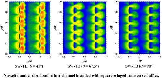
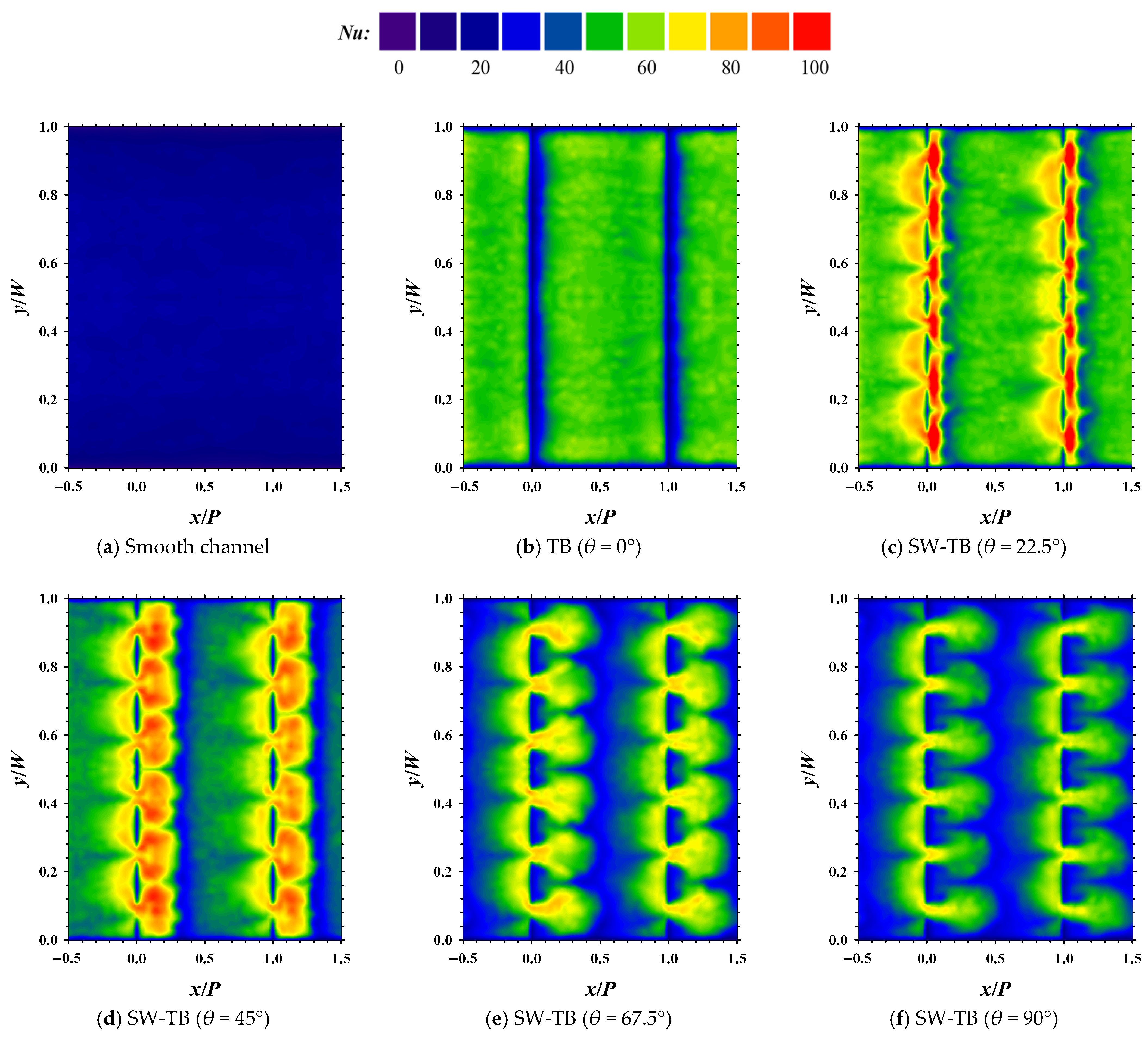
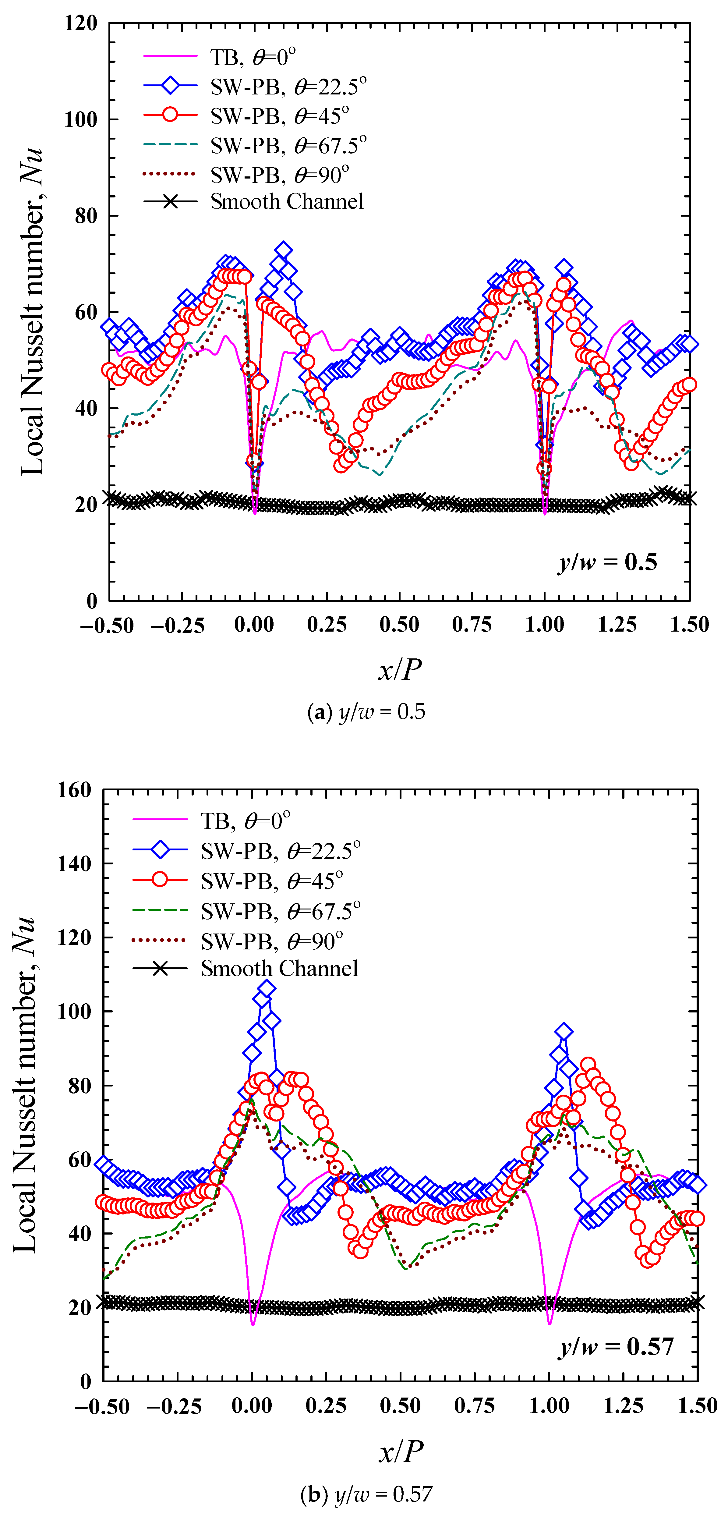
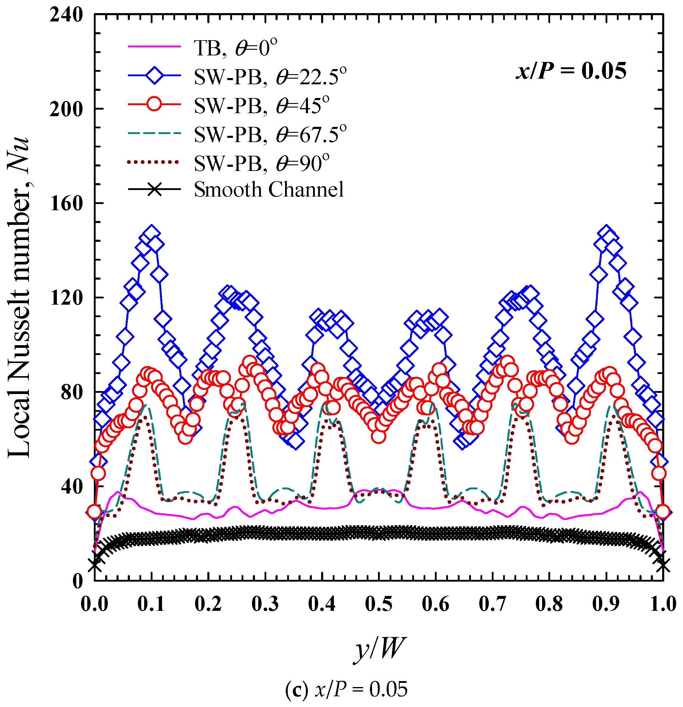
6.1. Local Nusselt Number Characteristics

Figure 4 and Figure 5 display the local Nusselt number profiles on the bottom wall, which was mounted with baffles having a blockage ratio (e/H) of 0.3 and a pitch ratio (p/H) of 1.5 at Re = 6000. Clearly, the presence of baffles resulted in greater heat transfer (Nu) than for the smooth channel. The channel equipped with perforated square-winged transverse baffles can generate impinging jet flows and recirculation behind the baffles. Impinging jets and recirculation promote fluid mixing in the near-wall region and behind the rear baffles. Figure 4b shows that heat transfer in a channel fitted with perforated square-winged transverse baffles is superior to that in a smooth channel.
Solid transverse baffles (TB, θ = 0°) gave moderate heat transfer rates between the baffles. However, the heat transfer rates were extremely low in the vicinity of the baffles (x/P = 0.0 and 1.0). These results can be explained since the baffles inhibited the flow reattachment around this area. Fluid flowed over the baffles and then reattached, causing flow recirculation, which helped enhance the heat transfer. For square-winged transverse baffles (SW-TBs) with square-wing attack angles of 22.5°, 45°, 67.5°, and 90°, high heat transfer rates appeared in the vicinity of the baffles (x/P = 0.0 and 1.0) due to the shapes of the multiple impingement flows. At larger square-wing attack angles, high heat transfer areas shifted further from the baffles due to changes in flow reattachment. Additionally, the high-heat-transfer areas became larger, reflecting the spreading of the reattachment and recirculation flow. However, at smaller square-wing attack angles, the intensities of the high heat transfer increased, and the dead zone became narrower. This indicates that impingement at smaller square-wing attack angles was stronger. Among all the square-winged transverse baffles, the ones with the square-wing attack angles (θ) of 22.5° and 45° showed the optimal results, signified by the high intensity and large heat transfer area, especially at x/P = 0.0–0.1 and x/P = 1.0–1.1, as seen in Figure 5a,b. The results reflect that the baffles with the optimum square-wing attack angle (θ) introduce strong impingement, which effectively washes the dead zones, as seen in Figure 5c. This enlarged area for heat transfer allows the fluid in the core and near-wall regions to mix evenly under the influence of irregular disturbances and impinging jet flows and recirculation, thereby enhancing the heat transfer. The influences of the two factors were amplified under turbulent flow conditions. Thus, the heat transfer capability increases with a decreasing square wing attack angle.

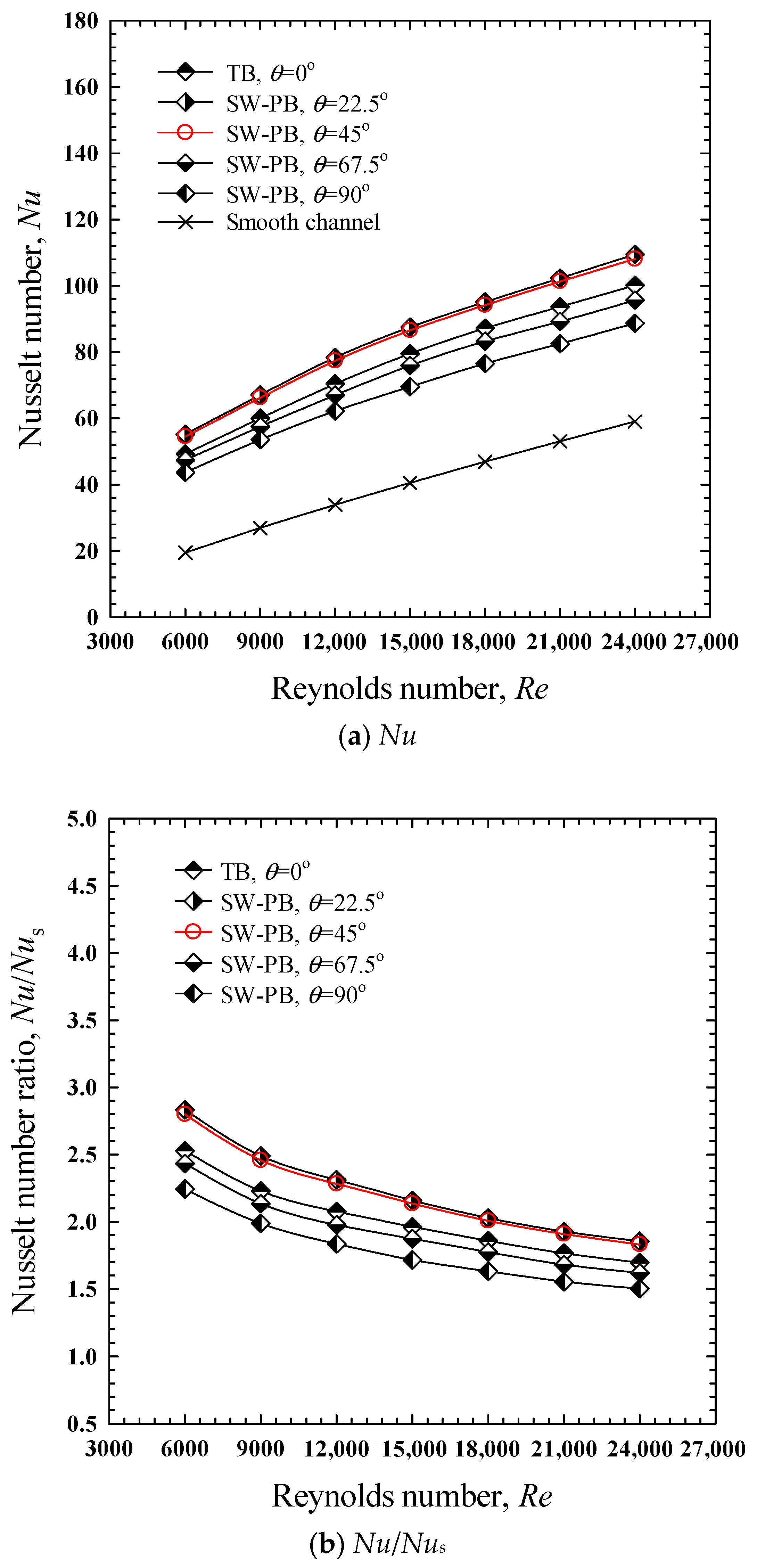
6.2. Average Heat Transfer Rate

Figure 6 shows the variation in the average heat transfer rate with Reynolds number for a channel containing SW-TBs with various square-wing attack angles (θ = 22.5°, 45°, 67.5°, and 90°) as well as a plain tube. The heat transfer rate (Nu) from the smooth channel is also plotted for comparison. The heat transfer rate increased with decreased square-wing attack angles (θ) and increased Reynolds number. Under all conditions, the heat transfer rate increased with the Reynolds number because of the higher intensity of the fluid turbulence. Under the same operating conditions, the channel fitted with square-winged transverse baffles (SW-TBs) significantly outperformed the smooth channel in terms of their Nusselt numbers. The results are due to the secondary flows described in Section 6.1. The consequences were stronger fluid collision and greater fluid fluctuation caused by the recirculation and longitudinal vortex flows that resulted in greater heat transfer. The SW-TBs with θ = 0° (solid transverse-baffle), 22.5°, 45°, 67.5°, and 90°, respectively, enhanced the heat transfer rate (Nu) by 69.6–152.9%, 85.4–183.4%, 83.05–179.9%, 61.9–143.3%, and 50.2–124.3% above those of the plain channel. The highest heat transfer rate among the square-wing attack angles (θ) was achieved for θ = 22.5°. Among the baffles, the SW-TBs with an attack angle of 45° yielded heat transfer rates that were superior to those with attack angles of 0°, 22.5°, 67.5°, and 90°, by around 7.95–10.68%, 0.99–1.29%, 13.04–15.46%, and 21.88–24.8%, respectively. As illustrated in Figure 5, the Nu/Nus ratios decreased as the Reynolds number (Re) increased. At 6000 ≤ Re ≤ 24,000, the Nu/Nus ratios increased using SW-TBs where θ = 0° (solid transverse baffle), 22.5°, 45°, 67.5°, and 90°, these being 1.69–2.53, 1.85–2.83, 1.83–2.79, 1.62–2.43, and 1.51–2.24, respectively.

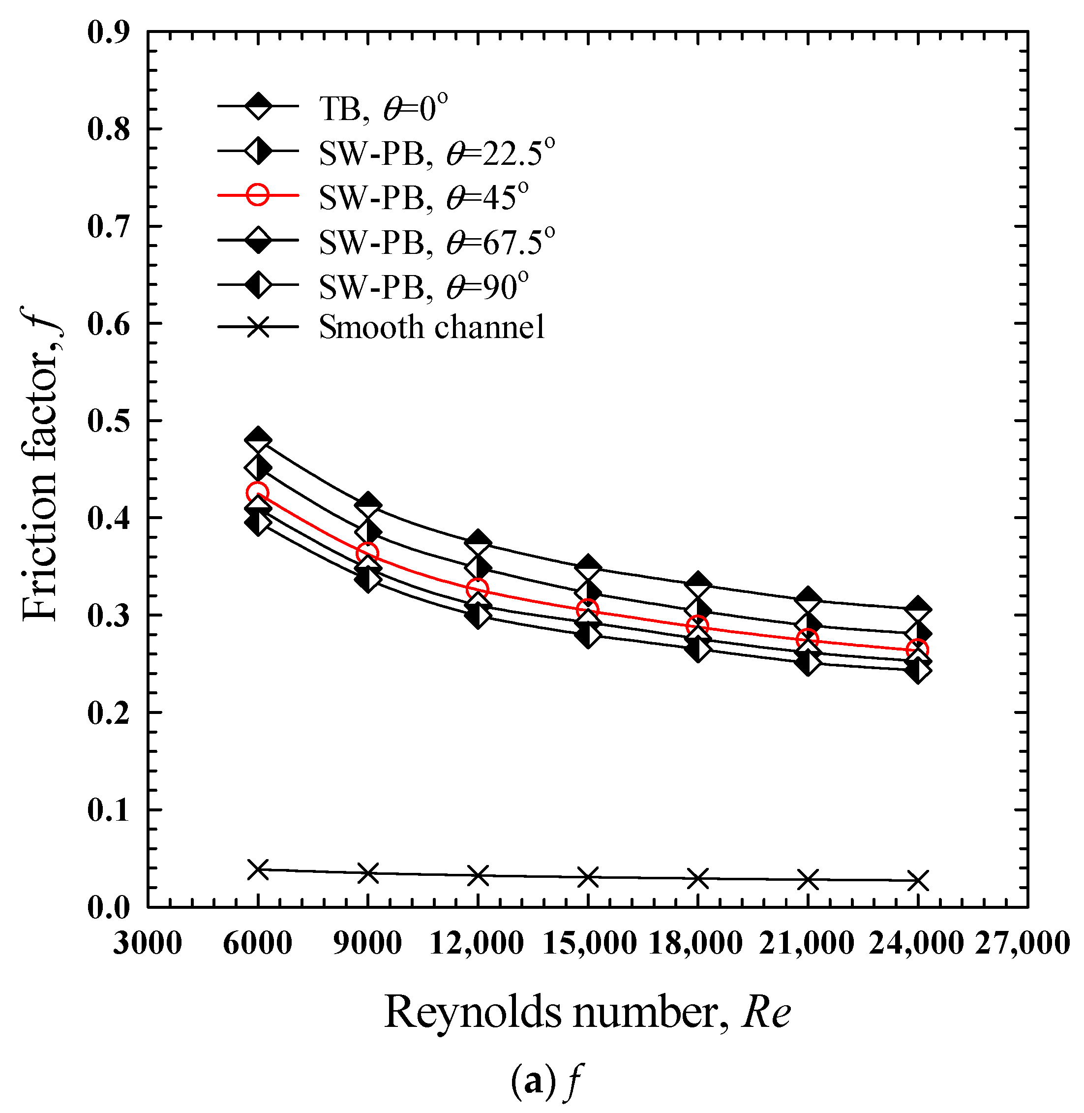
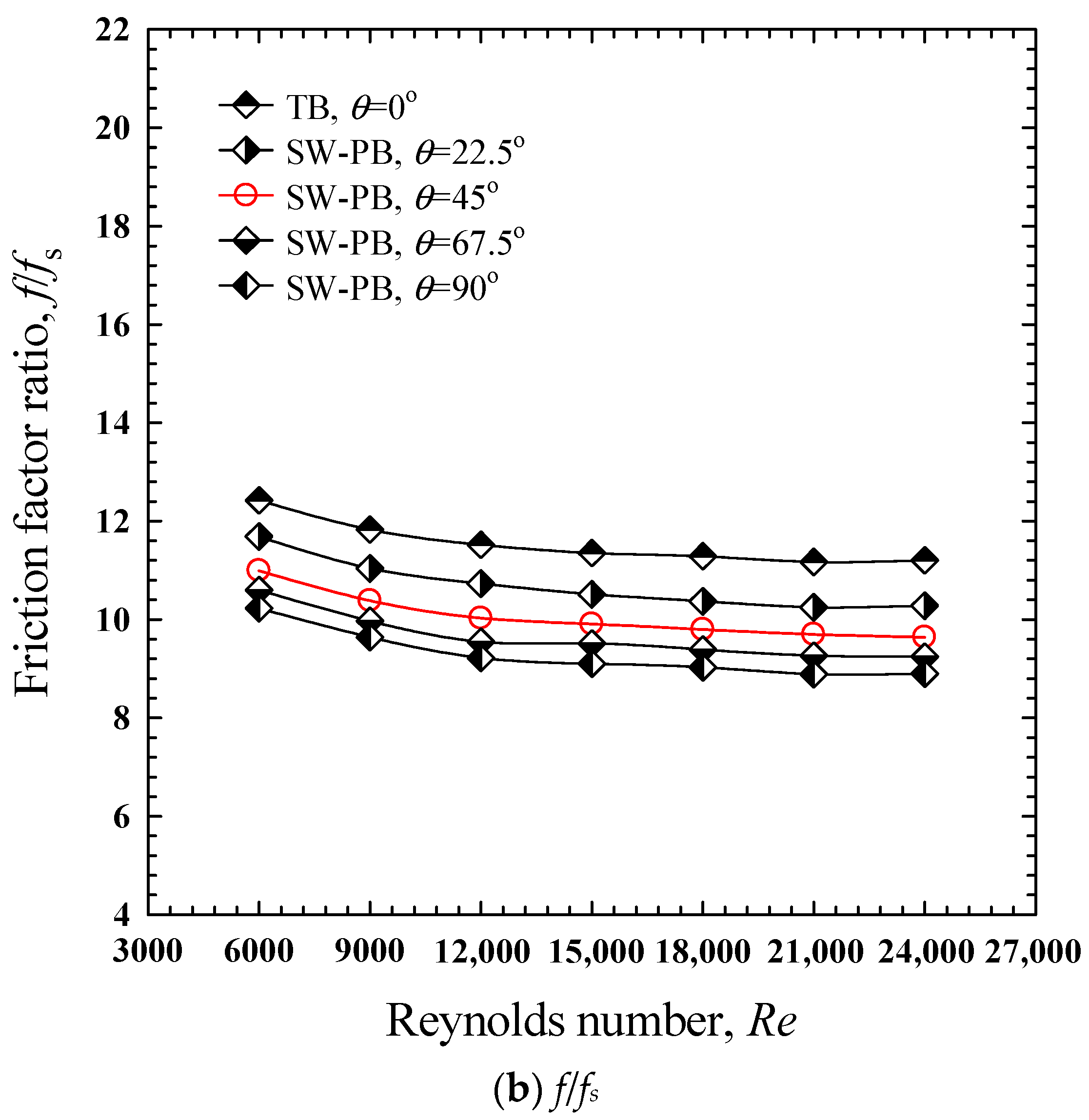
6.3. Friction Factor

The relationship between the pressure loss in terms of friction factor and Reynolds number for the channel fitted with square-winged transverse baffles (SW-TBs) at various attack angles (θ = 22.5°, 45°, 67.5°, and 90°) and Reynolds numbers, is presented in Figure 7, along with the results for a smooth channel. The influence of the square-winged transverse baffles (SW-TBs) on the friction factor (f) is shown in Figure 7a. These finding suggests that the channel fitted with square-winged transverse baffles (SW-TBs) caused an additional pressure drop, leading to higher friction factors as compared to a smooth channel. Contact between the large upwind area of the transverse baffles with square wings and air, long flow paths, and strong turbulence at the boundary layer caused intense turbulence, and the impinging jets were the main sources of the flow resistance change. Experimental results showed that SW-TBs caused a significant increase in the friction factor—6.5 to 36 times above the smooth channel. This is ascribed to flow obstruction, increased surface area, recirculation, and impinging flows generated by the SW-TBs. Generally, the recirculation/reverse flow induces a much greater increase in friction factor than axial flow does. Additionally, friction was also caused by increased contact area and dynamic pressure dissipation. Figure 8 reveals that an increase in the air velocity (Reynolds number) led to a drop in the friction factor (f) because the friction between the surface of the SW-TBs and the air was reduced. For 6000 ≤ Re ≤ 24,000, the use of SW-TBs with θ = 0° (solid transverse-baffle), 22.5°, 45°, 67.5° and 90°, respectively, yielded f/fs ratios of 11.17–12.42, 10.25–11.69, 9.64–10.99, 9.24–10.59, and 8.89–10.23. In other word, the friction factors (f) caused by the solid transverse baffles were greater than those caused by SW-TBs with θ = 22.5°, 45°, 67.5°, and 90°, by up to 1.06–1.09, 1.13–1.16, 1.17–1.21, and 1.21–1.26 times, respectively. The results indicate that the presence of a gap in the SW-TBs helped to reduce the friction loss as compared to the solid one.

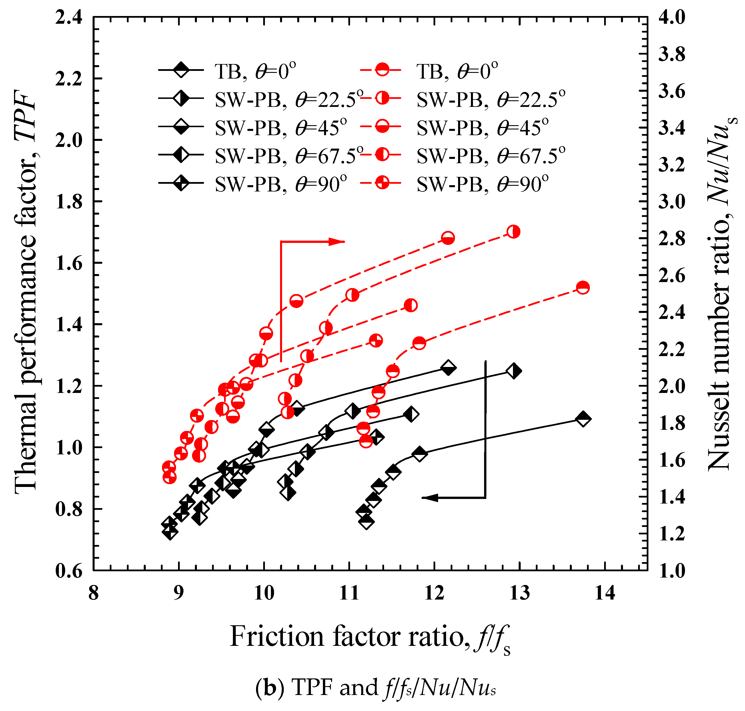
6.4. Thermal Performance Evaluation

The thermal performance factor (TPF) is defined by Equation (13). Figure 8 shows the variation in TPF with Re for channels with square-winged transverse baffles (SW-TBs) installed. Figure 8a,b depict the effect of the square-winged transverse baffles (SW-TBs) on the thermal performance factor (TPF) at an equal pumping power. For all square-winged transverse baffles, increased Re values reduced the TPF. Overall, TPF varies from 0.76 to 1.26, which indicates that a channel with square-winged transverse baffles (SW-TBs) installed may not achieve the expected energy saving under turbulent flow. However, channels with square-winged transverse baffle (SW-TB) inserts are advantageous in terms of energy saving at low Reynolds numbers (Re). The TPFs for SW-TBs with low wing attack angles (θ = 22.5°, 45°, and 67.5°) were above unity and substantially higher than that produced by a solid baffle (θ = 0°) under similar flow conditions. This suggests that SW-TBs offer an advantage over using solid baffles. For all SW-TBs examined, the TPF tended to increase as the attack angle (θ) decreased. For 6000 ≤ Re ≤ 24,000, the thermal performance factor (TPF) values for SW-TBs with θ = 0°, 22.5°, 45°, 67.5°, and 90° were in the ranges of 0.76–1.09, 0.85–1.25, 0.86–1.26, 0.77–1.11, and 0.72–1.03, respectively. The SW-TBs with an attack angle of 45° presented a greater TPF than other SW-TBs owing to the resultant high heat transfer and moderate friction losses. The thermal performance (TPF) of the SW-TBs at an attack angle of 45° were found to be 13.21–15.28%, 0.75–0.95%, 11.47–13.64%, and 18.67–21.84% greater than those channels with θ = 0°, 22.5°, 67.5°, and 90°, respectively.

6.5. Comparison with the Relevant Works

In Figure 9, the thermal performance factors (TPF) for the square-winged transverse baffles (SW-TBs, θ = 45°) are compared to those for previously modified transverse baffles of various designs. Such designs include inclined perforated baffles (baffle height ratio of 0.5, baffle pitch ratio of 10, hole position ratio of 0.266, and open area ratio of 12%) [10]; inline/staggered perforated baffles (perforation ratio of 40%) [11]; staggered and partially tilted perforated baffles (tilt angle of 45° and perforation ratio of 40%) [17]; and V-shaped perforated baffles (e/H = 0.285–0.6, P/e = 1.0–4.0, and open area ratio of 12–44%) [22]. According to Figure 9, inclined perforated baffles [10] had a better thermal performance (TPF) than the others. The thermal performance (TPF) values offered by the current square-winged transverse baffles (SW-TBs, θ = 45°) were moderate compared to the V-shaped perforated baffles [22]. It is noteworthy that the thermal performance (TPF) of the SW-TBs (θ = 45°) was greater than those of the inline/staggered perforated baffles [11] and staggered and partially tilted perforated baffles [17], while it was lower than those of inclined perforated baffles [10] for all Reynolds number and V-shaped perforated baffles [22] at the low Reynolds numbers.

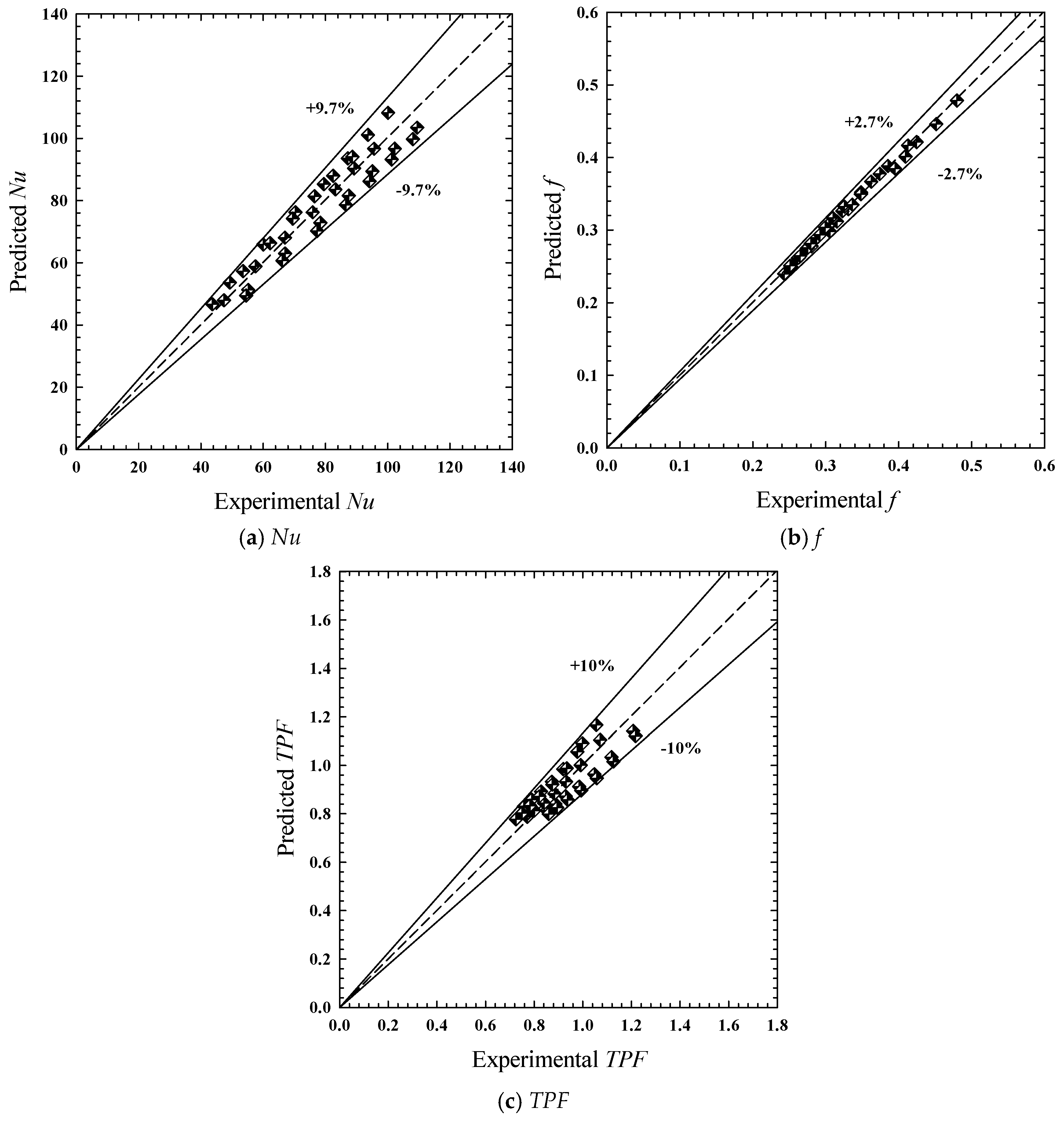
6.6. Empirical Correlation of Heat Transfer (Nu) and Friction Factor (f) and TPF

The experimental findings demonstrated that the geometries of the square-winged transverse baffles (SW-TBs) had a significant impact on Nu, f, and TPF. The established correlations were a function of the wing attack angle (θ), flow characteristics (Re), and fluid properties (Pr), as indicated by Equations (19)–(21).
Nu = f1(Re, Pr, θ)
f = f2(Re, θ)
TPF = f3(Re, θ)
All correlations for the range of the present experimental setup and parameters were developed using multiple regression, including correlations for the Nusselt number (Nu), friction factor (f), and TPF. Equations (22)–(24) provide empirical correlations obtained from studies done in the range of 6000 < Re < 24,000. In the present work, the predicted results from these equations were verified, and the outcomes are displayed in Figure 10a–c.
N u   =   1.878 Re 0.506 Pr 0.4 ( 90 + θ ) 0.201
f   =   38.472 Re 0.342 ( 90 + θ ) 0.314
T P F   =   15.101 Re 0.244 ( 90 + θ ) 0.097
A comparison of the experimental data and correlations for Nu, f, and TPF is shown in Figure 10a–c. The predicted data for Nu, f, and TPF deviate from the experimental data, within ±9.7%, ±2.7%, and ±10%, respectively. The deviations are mainly due to the experimental inconsistencies, including the turbulent fluctuation, axial heat loss, and textured surface of the square-winged transverse baffles.

7. Conclusions

The heat transfer enhancement behaviors of square-winged transverse baffles (SW-TB) were experimentally investigated using a thermochromic liquid crystal (TLC) sheet. Local heat transfer distributions were visualized and presented for a better understanding of the heat transfer mechanisms.
The important findings of this investigation are summarized as follows:
The SW-TBs where θ = 0°, 22.5°, 45°, 67.5°, and 90°, respectively, showed augmented heat transfer of 69.6–152.9%, 85.37–183.4%, 83.05–179.9%, 61.9–143.3%, and 50.2–124.3% over that of a smooth channel. The enhanced heat transfer corresponded to TPF values of 0.76–1.09, 0.85–1.25, 0.86–1.26, 0.77–1.11, and 0.72–1.03, respectively.
Square-winged transverse baffles (SW-TBs) have a practical design for decreasing the pressure drop penalty. They are useful in designing baffles that promote energy savings.
Square-winged transverse baffles (SW-TBs) promoted recirculation flow and induced multiple impinging flows behind each baffle. This allowed better contact between the fluid flow and the channel wall, and thus more efficient heat transfer.

Author Contributions

Validation, K.W. and V.C.; Formal analysis, M.P.; Data curation, A.P. and V.C.; Writing—original draft, S.E.-A.; Writing—review & editing, N.M. and M.H. All authors have read and agreed to the published version of the manuscript.

Funding

This research received no external funding.

Conflicts of Interest

The authors declare no conflict of interest.

Nomenclature

asquare perforated height, (m)
Aheat transfer area
Aincross-sectional channel area of the flow entrance
bsquare perforated width, (m)
cdistance between the square perforated, (m)
cpspecific heat of air at constant pressure, (J/kg K)
Dhhydraulic diameter, (m)
ffriction factor of channel with baffles, (-)
fsfriction factor of smooth channel, (-)
hbaffle height, (m)
Hchannel height, (m)
hcoefficient of heat transfer, (W/m2 K)
Icurrent, (amp)
kfthermal conductivity of air, (W/m K)
Lair flow passage length, (m)
m ˙ air mass flow rate, (kg/s)
NuNusselt number of channels with baffles, (-)
NusNusselt number of smooth channels, (-)
ptransverse baffle pitch length, (m)
Pstatic pressure, (Pa)
ΔPpressure drop, (Pa)
Qaheat gain of air, (W)
Qconvheat convection, (W)
ReReynolds number, (-)
tbaffle thickness, (m)
Tbbulk temperature of air, (K)
Tiinlet temperature of air, (K)
Tooutlet temperature of air, (K)
Twwall temperature of heater plate, (K)
uair inlet velocity, (m/s)
Vvoltage, (volts)
V ˙ volumetric flow rate, (m3/s)
Wchannel width, (m)
Greek symbols
θattack angle of square wing (degrees)
μviscosity of air, (Ns/m2)
βopening area ratio
ρdensity of air, (kg/m3)
Subscripts
aair
bbulk
conconvective
ffluid
hhydraulic
iinlet
ooutlet
wwall
Abbreviations
PBperforated baffle
PLApolylactic acid
RTDresistance temperature detectors
SW-TB square-winged transverse baffle
TLCthermochromic liquid crystals
TPFthermal performance factor

References

  1. Alqarni, M.S.; Memon, A.A.; Anwaar, H.; Usman; Muhammad, T. The forced convection analysis of water alumina nanofluid flow through a 3D annulus with rotating cylinders via κ-ε turbulence model. Energies 2022, 15, 6730. [Google Scholar] [CrossRef]
  2. Khatri, R.; Goswami, S.; Anas, M.; Sharma, S.; Agarwal, S.; Aggarwal, S. Performance evaluation of an arched plate solar air heater with porous aluminum wire mesh cylindrical fins. Energy Rep. 2020, 6, 627–633. [Google Scholar] [CrossRef]
  3. Kumar, A.; Kim, M.H. Heat transfer and fluid flow characteristics in air duct with various V-pattern rib roughness on the heated plate: A comparative study. Energy 2016, 103, 75–85. [Google Scholar] [CrossRef]
  4. Promvonge, P.; Eiamsa-ard, S.; Wongcharee, K.; Chuwattanakul, V.; Samruaisin, P.; Chokphoemphun, S.; Nanan, K.; Eiamsa-ard, P. Characterization of heat transfer and artificial neural networks prediction on overall performance index of a channel installed with arc-shaped baffle turbulators. Case Stud. Therm. Eng. 2021, 26, 101067. [Google Scholar] [CrossRef]
  5. Kumar, R.; Sethi, M.; Chauhan, R.; Kumar, A. Experimental study of enhancement of heat transfer and pressure drop in a solar air channel with discretized broken V-pattern baffle. Renew. Energy 2017, 101, 856–872. [Google Scholar] [CrossRef]
  6. Feng, C.N.; Liang, C.H.; Li, Z.X. Friction factor and heat transfer evaluation of cross-corrugated triangular flow channels with trapezoidal baffles. Energy Build. 2022, 257, 111816. [Google Scholar] [CrossRef]
  7. Karwa, R.; Maheshwari, B.K. Heat transfer and friction in an asymmetrically heated rectangular duct with half and fully perforated baffles at different pitches. Int. Commun. Heat Mass Transf. 2009, 36, 264–268. [Google Scholar] [CrossRef]
  8. Ary, B.K.P.; Lee, M.S.; Ahn, S.W.; Lee, D.H. The effect of the inclined perforated baffle on heat transfer and flow patterns in the channel. Int. Commun. Heat Mass Transf. 2012, 39, 1578–1583. [Google Scholar] [CrossRef]
  9. Sriromreun, P.; Thianpong, C.; Promvonge, P. Experimental and numerical study on heat transfer enhancement in a channel with Z-shaped baffles. Int. Commun. Heat Mass Transf. 2012, 39, 945–952. [Google Scholar] [CrossRef]
  10. Kumar, R.; Nadda, R.; Kumar, S.; Razak, A.; Sharifpure, M.; Aybar, H.S.; Saleel, C.A.; Afzal, A. Influence of artificial roughness parametric variation on thermal performance of solar thermal collector: An experimental study, response surface analysis and ANN modelling. Sustain. Energy Technol. Assess. 2022, 52, 102047. [Google Scholar] [CrossRef]
  11. El Habet, M.A.; Ahmed, S.A.; Saleh, M.A. Thermal/hydraulic characteristics of a rectangular channel with inline/staggered perforated baffles. Int. Commun. Heat Mass Transf. 2021, 128, 105591. [Google Scholar] [CrossRef]
  12. Boonloi, A.; Jedsadaratanachai, W. CFD analysis on heat transfer characteristics and fluid flow structure in a square duct with modified wavy baffles. Case Stud. Therm. Eng. 2022, 29, 101660. [Google Scholar] [CrossRef]
  13. Bhattacharyya, S.; Vishwakarma, D.K.; Goel, V.; Chamoli, S.; Issakhov, A.; Meyer, J.P. Thermodynamics and heat transfer study of a circular tube embedded with novel perforated angular-cut alternate segmental baffles. J. Therm. Anal. Calorim. 2021, 145, 1445–1465. [Google Scholar] [CrossRef]
  14. Faujdar, S.; Agrawal, M. Computational fluid dynamics based numerical study to determine the performance of triangular solar air heater duct having perforated baffles in V-down pattern mounted underneath absorber plate. Sol Energy 2021, 52, 235–252. [Google Scholar] [CrossRef]
  15. Tandel, H.U.; Modi, K.V. Experimental assessment of double-pass solar air heater by incorporating perforated baffles and solar water heating system. Renew. Energy 2022, 183, 385–405. [Google Scholar] [CrossRef]
  16. Khanlari, A.; Tuncer, A.D.; Sözen, A.; Aytaç, İ.; Çiftçi, E.; Variyenli, H.İ. Energy and exergy analysis of a vertical solar air heater with nano-enhanced absorber coating and perforated baffles. Renew. Energy 2022, 187, 586–602. [Google Scholar] [CrossRef]
  17. El Habet, M.A.; Ahmed, S.A.; Saleh, M.A. The effect of using staggered and partially tilted perforated baffles on heat transfer and flow characteristics in a rectangular channel. Int. J. Therm. Sci. 2022, 174, 107422. [Google Scholar] [CrossRef]
  18. Webb, R.L. Performance evaluation criteria for use of enhanced heat transfer surfaces in heat exchanger design. Int. J. Heat Mass Transf. 1981, 24, 715–726. [Google Scholar] [CrossRef]
  19. Nanan, K.; Thianpong, C.; Pimsarn, M.; Chuwattanakul, V.; Eiamsa-ard, S. Flow and thermal mechanisms in a heat exchanger tube inserted with twisted cross-baffle turbulators. Appl. Therm. Eng. 2017, 114, 130–1475. [Google Scholar] [CrossRef]
  20. Kline, S.J.; McClintock, F.A. Describing Uncertainties in Single Sample Experiments. Mech. Eng. 1953, 75, 3–8. [Google Scholar]
  21. Bergman, T.L.; Lavine, A.S.; Incropera, F.P.; Dewitt, P.D. Fundamentals of Heat and Mass Transfer, 7th ed.; John Wiley & Sons Inc.: Hoboken, NJ, USA, 2011. [Google Scholar]
  22. Chamoli, S.; Thakur, N.S. Correlations for solar air heater duct with V-shaped perforated baffles as roughness elements on absorber plate. Int. J. Sustain. Energy 2016, 35, 1–20. [Google Scholar] [CrossRef]
Figure 1. Previously designed perforated baffles. (a) Inline/staggered perforated baffles [11]. (b) Inclined perforated baffles [10]. (c) V-down pattern perforated baffles [14]. (d) Perforated baffles [15]. (e) Perforated baffles [16]. (f) Staggered and partially tilted perforated baffles [17].
Energies 15 08736 g001aEnergies 15 08736 g001b
Figure 2. (a) Design of the channel and square-wing transvers baffles; (b) the structures of the channels into which the square-winged transverse baffles were installed, with various wing attack angles (θ); and (c) the experimental setup.
Energies 15 08736 g002aEnergies 15 08736 g002b
Figure 3. Validation test of a smooth channel: (a) Nusselt number as a function of Reynolds number; and (b) friction factor as a function of Reynolds number.
Energies 15 08736 g003aEnergies 15 08736 g003b
Figure 4. Nusselt number distribution in a channel installed with square-winged transverse baffles (SW-TBs) at Re = 6000.
Energies 15 08736 g004
Figure 5. Normalized Nusselt number at y/w = 0.5, y/w = 0.57, and x/P = 0.05 at Re = 6000.
Energies 15 08736 g005aEnergies 15 08736 g005b
Figure 6. Nusselt number (Nu) and Nusselt number ratio (Nu/Nus) of a channel with square-winged transverse baffles (SW-TBs).
Energies 15 08736 g006
Figure 7. Friction factor (f) and friction factor ratio (f/fs) of a channel with square-winged transverse baffles (SW-TB).
Energies 15 08736 g007aEnergies 15 08736 g007b
Figure 8. Thermal performance of a channel with square-winged transverse baffles (SW-TBs).
Energies 15 08736 g008aEnergies 15 08736 g008b
Figure 9. Comparison of the current results and those reported in previously published articles [10,11,17,22].
Energies 15 08736 g009
Figure 10. Experimental data prediction results.
Energies 15 08736 g010
Table 1. The geometric parameters and conditions of the experiments.
No.ParameterValue
1Blockage ratio (h/H)0.2
2Pitch ratio (p/H)1.5
3Square-wing attack angles (θ)0°, 22.5°, 45°, 67.5°, and 90°
4Area ratio of the perforation holes0.21
5Aspect ratio (W:H)3.75
6Reynolds number (Re)6000–24,000
7Heat flux condition600 W/m2
Table 2. Uncertainties of the experimental parameters.
Experimental ParameterUnits(%) Maximum Uncertainties
Nu - 5.12
f - 4.98
Re - 4.6
TPF-5.2
Publisher’s Note: MDPI stays neutral with regard to jurisdictional claims in published maps and institutional affiliations.

