Abstract
Hydraulic fracturing is an important technology for the stimulation of oil and gas reservoirs. Conventional fracturing technology based on “sand-carrying” faces some challenges such as sand plugs; incompatibility with the well completion method; damage to the reservoir caused by the incomplete gel-breaking of the fracturing fluid; solid proppants inefficiently turning the corner in complex fracture networks, and so on. In this paper, a novel self-generated proppant fracturing fluid system is proposed to solve the above problems caused by “sand-carrying”. The advantage of the fracturing fluid system is that in the whole process of fracturing, no solid proppants will be injected. The fracturing fluid itself will transform into solid proppants in the induced fractures under high temperatures to resist fracture closure stress. The fluid system consists of two kinds of liquids. One is the phase change liquid (PCL), which occurs as a liquid–solid phase change at high-formation temperatures to form a solid proppant. The other is the non-phase change liquid (NPCL), which controls the dispersity of the PCL in the two-phase fluid system. The main building block of the PCL is confirmed to be the bisphenol-A diglycidyl ether-type epoxy resin, whereas the NPCL is mainly composed of surfactants. The viscosity, phase-change temperature, and time of the fracturing fluid system are, respectively, about 30 mPa·s, 80 °C, and 20 min.
1. Introduction
Hydraulic fracturing, as the main technology for the stimulation of oil and gas reservoirs, has been widely used in the field. Since the advent of this technology in 1947, remarkable progress has been made in the materials and techniques used after decades of development [1]. However, conventional hydraulic fracturing based on “sand-carrying” still has some limitations and challenges [2]:
- (1)
- During proppant transport, the density of the proppant is much higher than that of the carrying fluid, which makes the proppants settle at the bottom of the fractures and causes an accumulation at the entrance of the fractures [3]. To achieve the goal of suspending the proppants in the carrying fluid, the viscosity of the fluid is usually raised by adding thickening agents. Although this solves the settlement of the proppants, other problems arise [4]. For instance, polymer gels may be left over as residues from the formation process which causes damage [5], or there may be some potential risks in the construction process with the pump pressure and the friction in the pipe being very high due to the use of high-viscosity liquids [6].
- (2)
- In a complex fracture network, the solids may not effectively turn the corner at the junction of the intersecting fractures, which limits the transported distance in the branch fractures and is even likely to bridge off at these intersections leaving only the main planar fracture propped [7].
- (3)
- The proppant placement in conventional fracturing is homogeneous and continuous in the fractures, which makes the flow of oil and gas seep through the intergranular pores of the solid particles, causing the limitations of the reservoir stimulation [8].
To deal with the problems discussed above, a novel self-generated proppant fracturing fluid system is proposed in this paper. No solid proppants will be injected in the process of fracturing, except for two kinds of liquids (PCL and NPCL) that act as both fracturing fluids and proppants. The fracturing with the new fluid system has the following advantages:
- (1)
- No solid injection releases the limitations of the well completion mode on the fracturing. Problems such as sand plugs, high friction inside the tubes, and gel residue damage can be solved. In addition, the high viscosity of the fracturing fluid is no longer required.
- (2)
- The liquids can effectively turn the corner at the junction of the intersecting fractures in the complex fracture network. The limitations of solid transportation can be solved in the branch fractures, which makes both the main planar fractures and branch fractures prop.
- (3)
- The proppant placement controlled by two-phase flow patterns is discontinuous and heterogeneous due to the two kinds of liquids flowing separately in the fractures, which greatly increases the fracture conductivity.
2. Study on the PCL
2.1. Design Principles of the PCL
- (1)
- Sensitive stimuli-responsive
It can recognize external stimuli and only make an established response to a single stimulus. The external stimulation conditions are set to a high temperature, and the PCL only rapidly transforms from a liquid to a solid under a high-temperature environment.
- (2)
- Long-term stability
Long-term stability includes liquid long-term stability and solid long-term stability. The long-term stability of a liquid means that the PCL’s properties will not change when stored at room temperature for a long time. The long-term stability of the solid refers to the physical and chemical properties of the solid, which, when convert from the PCL, do not change under high temperatures, high pressure, and long-term contact with the organic solvent, strong acid, strong base, and so on.
- (3)
- Phase-change behavior and properties of cured products are controlled
The time and temperature factors affecting the phase transformation behavior, the strength and hardness of the solidified product, and other factors can have a significant impact on the fracturing construction process and the fracturing construction effect can be controlled. This allows the phase-change fracturing fluid to meet different geological conditions and ambient temperatures and match different fracturing processes and achieve a good fracturing effect at the same time.
- (4)
- Chemical inertness
When the phase-change fracturing fluid makes contact with the formation fluid (crude oil or formation water), the commonly used downhole working fluid, and clay minerals, it will not react with them to produce flocc or precipitation or cause damage to the reservoir, adversely affecting the phase-change behavior.
- (5)
- Easy to inject
The PCL should have low viscosity and friction resistance and show good liquid fluidity and deformation ability in the pipeline, wellbore, and fracture flow before reaching the phase-change temperature so as to reduce the water head loss in the process and reduce the wellhead pump pressure. In fractures, fluid flows over longer distances and is more easily diverted at fracture-to-fracture junctions, allowing better communication between the branch and natural fractures.
- (6)
- Immiscible
The PCL and NPCL always occupy their own flow channels in pipelines, wellbores, and fractures, and there will be no dissolution of one phase in another phase.
2.2. Component Screening of PCL
Thermal stimuli-responsive materials can meet the requirements for the PCL using the above design principles. This kind of material is usually a liquid prepolymer with a small molecular weight. Through a chemical reaction with the initiator under heating conditions, the prepolymer is transformed from liquid into solid, forming a linear or three-dimensional network structure [9].
- (1)
- Unsaturated polyester
Unsaturated polyester is a kind of linear polymer compound with multifunctional groups, which is generated by unsaturated (or saturated) diacid and dialcohol through a polycondensation reaction. Unsaturated polyester polymers contain both ester bonds and unsaturated double bonds on the main chain, with carboxyl and hydroxyl groups at both ends of the macromolecular chain. The structural type is shown in Figure 1.

Figure 1.
Schematic diagram of unsaturated polyester structure.
The double bonds on the main chain of the molecule can be cross-linked with other monomers containing double bonds by free radical copolymerization. The process is divided into four stages: chain initiation, chain propagation, chain termination, and chain transfer. After the reaction, the molecular structure changes from linear to large molecules with a three-dimensional network structure. The increase in the molecular weight makes the unsaturated polyester complete the transformation from liquid to solid [10].
The biggest advantages of using an unsaturated polyester polymer as the PCL are that the ① requirement for the phase transition temperature is not particularly high; ② synthesis process of the liquid system is simple; ③ cured product has a certain tensile, bending, and compression resistance; and ④ cured product has good chemical resistance.
The disadvantages are that the ① volume shrinkage of the cured product is large; ② strength and modulus of the cured product are relatively low compared to other thermal stimuli-responsive materials; ③ heat resistance of the cured product is poor and the thermal deformation temperature is about 50~60 °C; and ④ cured product has poor resistance to organic solvents.
- (2)
- Phenolic resin
These polymer compounds are mainly obtained by the condensation polymerization of phenol and formaldehyde under alkaline conditions [11]. The molecular structure is mainly linear, containing the hydroxyl methyl active group on the molecular main chain of the polymer. Condensation reactions can occur under alkaline (NaOH), acidic (organic acid), metal oxide, or direct heating conditions from small molecule monomer condensation to macromolecule polymer; the macroscopic performance is from liquid converting into solid. The molecular structure is shown in Figure 2. When the prepolymer with the benzyl alcohol structure on the benzene ring has a phase change, the alcohol hydroxyl group attacks the hydrogen atom on the ortho- or para-position of the phenolic hydroxyl group on the benzene ring, forming a methylene bridge to combine two small molecules and remove a molecule of water [12,13,14].

Figure 2.
Schematic diagram of linear polymer structure.
Compared with other thermal stimuli-responsive materials, the main advantages of using this kind of polymer as the phase-change fracturing fluid include the following [15,16,17]: ① The cured product has a high-temperature resistance. Even under very high-temperature conditions, it can maintain the integrity and dimensional stability of its structure. As a proppant, it will be in a high-temperature environment for a long time during the formation, and its high-temperature resistance has great advantages for maintaining the flow conductivity for a long time. ② The cured product has good chemical stability, and the solid proppant after the phase change can resist the dissolution or decomposition of most chemicals. ③ The price of the raw materials is low, the synthesis process of the liquid system is simple and mature, and the investment in the synthesis and processing equipment is small; therefore, it is highly economical to produce.
The disadvantages are as follows: ① The mechanical properties of the cured products are lower than those of other kinds of thermal stimuli-responsive materials. As a proppant, its ability to resist a high closing pressure and maintain fracture conductivity is questionable [18]. ② The curing reaction rate during the phase transformation process is low, and it takes a long time to complete curing, which may require a long time for well shut-in and liquid flowback. ③ The phase-change process is a condensation reaction, accompanied by the formation of by-products. ④ The temperature and pressure required for complete solid formation are relatively high, and the solid material formed is hard but brittle [19].
- (3)
- Urea-formaldehyde resins
This kind of compound is mainly based on carbamide and formaldehyde as the raw materials, under the action of catalyst (alkaline or acidic) polycondensation to form a variety of methylol urea, and then dehydration condensation between the methylol urea molecules into a linear polymer. Before curing, it is a polymer composed alternately of substituted urea, methylene, or a small amount of dimethylene. During curing, the molecules react with -NH- to form a three-dimensional network structure [20,21].
These polymers have the following advantages as the PCL: ① They are fast in the curing reaction rate, and the well shut-in time after the completion of on-site construction is required to be short so it can flow back quickly. ② They have a certain resistance to chemical corrosion or corrosion and can resist both a weak acid and a weak alkali. ③ Raw materials are readily available at low prices.
However, the disadvantages of using such materials as the PCL are as follows: ① The cured product has poor mechanical properties, which makes it easy to be broken under a high closure pressure. Maintaining the conductivity of fractures for a long time is doubtful [22]. ② It easily decomposes under the conditions of a strong acid or alkali, which makes it difficult to guarantee the long-term stability of the cured product in the working fluid of the downhole. ③ The high curing shrinkage rate makes great changes to the morphology and size of the cured product, which increases the instability in the downhole work as a proppant.
- (4)
- Epoxy resin
This kind of polymer molecule with two or more epoxy groups due to the chemical activity of the epoxy groups can be used for a variety of compounds containing active hydrogen (such as amine, anhydride, etc.) to make the ring-opening cross-linking reaction [23]. Finally, a polymer with a three-dimensional spatial network structure is formed. There are many kinds of these polymers [24]. According to their different structures, they are mainly divided into the following types, as shown in Table 1.

Table 1.
Epoxy resins with different molecular structures.
Although there are many kinds of polymers with epoxy groups, most of them are mainly glycidyl ether structures, and the other groups connected by epoxy groups through ether bonds are mainly bisphenol-A [25]. The chemical structure is shown in Figure 3.

Figure 3.
Structure diagram of bisphenol-A epoxy resin.
Compared with other thermal stimuli-responsive materials, this kind of polymer has more advantages than the PCL: ① Because the molecular structure contains groups with high activity and strong polarity, such as epoxy groups, hydroxyl groups, and ether bonds, the intermolecular force is stronger [26]. ② Due to the dense molecular structure, there is strong cohesion between and within molecules. The aromatic ring in the phenolic group makes the molecule have high rigidity. Macroscopically, the solid material formed after the phase change has higher strength and hardness compared with other thermal stimuli-responsive materials [27]. ③ The curing process is an addition reaction without water or other volatile by-products, and the curing shrinkage is as low as 1~2%. ④ As the PCL, it has good long-term storage stability. ⑤ The cured product has a good heat resistance and the maximum heat resistance temperature can reach more than 200 °C, which can adapt to most oil and gas reservoirs. ⑥ The cured product has great chemical stability with the ability to resist a strong acid or alkali. ⑦ The curing process is simple. By matching different polymer curing agent systems, the reaction can be carried out in a temperature range of 0~180, which can adapt to different formation temperatures [28].
In summary, unsaturated polyester, phenolic resin, and urea-formaldehyde resins are obtained by polycondensation, which produces the by-products and has a great shrinkage of the cured products. In addition, the cured products of unsaturated polyester have poor heat resistance and low heat distortion temperatures, which cannot meet the high-temperature environment in the downhole. The curing time of phenolic resin is too long to meet the requirements of the flowback. The solid materials converted from urea-formaldehyde resins have poor chemical stability and are not compatible with the downhole fluids. However, the epoxy resin was obtained by an addition reaction without the by-products and shrinkage of the cured products. The solid materials converted from epoxy resin have great heat resistance and chemical stability, which can resist the closure stress to support the fractures to maintain conductivity in high-temperature environments and under strong acid or alkali conditions. In addition, the curing time can be adjusted by different curing agents, which has little impact on the flowback. These advantages can meet the conditions required in the design principles of the PCL. Therefore, bisphenol-A epoxy resin is selected as the basis of the phase-change fracturing fluid system.
2.3. Synthesis of the PCL
The bisphenol-A diglycidyl ether can be synthesized directly from epichlorohydrin and diphenol-propane under alkaline conditions [29]. The reaction steps mainly include a ring-opening reaction, propagation reaction, and ring-closure reaction. The reaction mechanism is shown in Table 2.

Table 2.
Reaction mechanism of bisphenol-A diglycidyl ether.
A blender, a thermometer, condensation tube, and constant pressure-drop funnel were loaded into a four-mouth flask, and certain amounts of epichlorohydrin and diphenyl propane were added to the prepared flask, and then the flask was heated at about 75 °C. The mixture was stirred in the flask until the diphenyl propane was dissolved and then drops of NaOH were slowly added to the mixture, keeping the temperature in the flask at about 70 °C. After the NaOH was added, the temperature in the flask was maintained at 70~80 °C and the reaction continued for a period of time until the liquid turned yellow and the reaction stopped. When the temperature in the flask decreased, distilled water and benzene solution were slowly added to the flask, the mixture was fully stirred, the water was separated using a separating funnel, and then the solution was washed with distilled water several times until it was neutral. The separated organic layer was distilled under atmospheric pressure to remove most of the benzene and then the residual solvent, water, and unreacted epichlorohydrin were removed by vacuum distillation to obtain a yellow viscous liquid [30]. The experimental instruments and materials are shown in Table 3.

Table 3.
Experimental instruments and materials.
The experimental results are shown in Figure 4a. The viscosity of the PCL was about 200 mPa·s with a density of about 1.15 g/cm3. Figure 4b shows the solid material converted from the PCL under high-temperature conditions (about 80 °C). The cured product had a certain hardness but was brittle. The obtained phase-change liquid was tested for long-term stability. Considering the different seasons and storage environment temperatures, the experimental design was to store the PCL sealed without light for 15 days at 20 °C, 30 °C, and 45 °C to observe whether the liquid properties would change. The test results are shown in Figure 5a–c.
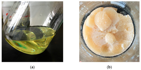
Figure 4.
The PCL and the cured product: (a) The PCL in liquid form; (b) The cured product converted from the PCL at a high temperature.
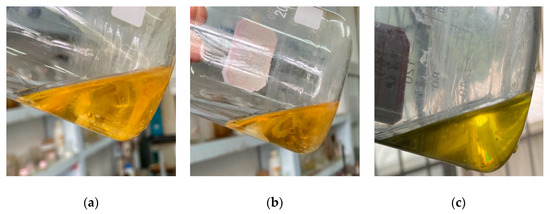
Figure 5.
Long-term stability test results of the PCL at different temperatures: (a) PCL at 20 °C for 15 days; (b) PCL at 30 °C for 15 days; (c) PCL at 45 ℃ for 15 days.
It can be seen in Figure 5 that the PCL had no change in properties but still had great fluidity. The curing reaction was carried out, which proved that there was no difference in the behavior and results of the reaction from those before. The test results show that the characteristics of the PCL could meet the requirements of the design principles of the phase-change fracturing fluid system.
2.4. Screening and Synthesis of Curing Agent (CA)
The PCL is a kind of prepolymer that needs to be cured at a high temperature under the joint action of the curing agent (CA). CAs can be divided into two types, reactive and catalytic. With the increase in the temperature, a reactive CA can react with the epoxy group in the PCL and become a part of the cured product [31]. The liquid system is further cross-linked from the initial linear structure to form a three-dimensional network structure through stepwise polymerization. In the polar covalent bond formed by the oxygen atom on the epoxy group and the carbon atom at the end of the main chain due to the large electronegativity of the oxygen atom and the strong attraction to the electron, the common electron in the C=O bond shifts to the oxygen atom, resulting in the oxygen atom forming a negatively charged enrichment region, and the carbon atom at the end of the main chain forming a positively charged enrichment region. The delocalization of positive and negative charges enables the epoxy group to react with nucleophiles or electrophiles to initiate ring-opening polymerization [32]. Therefore, reactive CAs usually have active hydrogen atoms such as aliphatic derivatives, organic acids, anhydrides, etc.
Under certain reaction conditions, a catalytic CA initiates the phase-change liquid to open the ring of its epoxy group and then carries out the curing reaction according to the process of cationic or anionic polymerization. The PCL forms a network structure through self-polymerization to form a homopolymer dominated by an ether bond. Compared with a catalytic CA, a reactive CA can participate in the curing reaction and become a part of the cured product. In addition, the properties of the cured product can be further optimized by modifying it.
Reactive CAs are mainly divided into amines and anhydrides. The curing reaction mechanism and the molecular structure of the cured products are shown in Table 4. The advantages and disadvantages of using these two curing agents as the phase-change fracturing fluid are shown in Table 5.

Table 4.
Reaction mechanism and products of different curing agents with the PCL.

Table 5.
Characteristics of the two curing agents as phase change fracturing fluid.
Based on these advantages, the curing agent meeting the requirements of the fracturing fluid system was synthesized through a laboratory test. The synthesis mechanism and infrared analysis results are shown in Figure 6 and Figure 7. Figure 7 shows that there was a strong absorption peak at 1770~1720 cm−1, corresponding to the stretching vibration of the C=O group. The moderate absorption peak at 1300~1000 cm−1 corresponds to the stretching vibration of C-O-C. The results of the infrared spectrum analysis indicated that the CA was synthesized, which meets the requirement of the phase change.
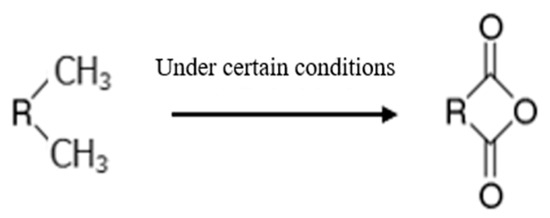
Figure 6.
The reaction mechanism of the CA.
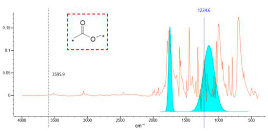
Figure 7.
The infrared spectrum of the curing agent. (The blue number indicates the wave number corresponding to the peak and the * indicates that any accessory can be connected such as functional group or atom).
2.5. Modification of the PCL and Testing of Cured Products
The high viscosity of the PCL and the low strength of the cured product cannot meet the requirements of injection and long-term conductivity. Therefore, it is necessary to further modify these defects of the PCL.
The viscosity of the PCL can be reduced by diluting it with solvent. The diluent can be divided into two types, reactive and non-reactive. Non-reactive diluent refers to solvents that do not contain epoxy groups in the molecular structure and will not react with the CA in the curing process. In addition, most of them will volatilize in the curing process. In addition to reducing the viscosity of the PCL, they will also affect the phase-change time and the heat resistance and strength of the cured products. Common non-reactive diluents include toluene, styrene, absolute ethanol, etc.
Reactive diluents usually refer to low-molecular-weight compounds with one or more epoxy groups. They can directly participate in the curing reaction of the PCL and become a part of the three-dimensional network of the macromolecular structure, which can introduce functional groups into the molecular structure of the cured products in the process of the reaction. Therefore, not only the viscosity of the PCL is reduced, but also the cured product can be modified. Reactive diluents include aliphatic, alicyclic and aromatic, etc. According to the molecular structure of the PCL and the principle of similar solubility, the molecular structure of diluents is designed as a glycidyl ether-type and an aromatic ring is introduced to give it good compatibility with the PCL. The introduction of the rigid group can also increase the mechanical properties of the cured products.
The diluent (RD) synthesized by this experiment was a colorless transparent liquid with a density of about 1.06 g/cm3. The RD was mixed with the PCL according to the different mass percentages and the viscosity of the PCL decreased rapidly with the mass of the RD to less than 15%. When the RD’s mass increased in the range of 15~20%, the viscosity of the mixed liquid system decreased slowly. When the mass of the RD exceeded 20%, the further downward trend of the viscosity was not obvious, which determined that the mass of the RD was 20% in the fluid system. The measured viscosity of the mixture after dilution was about 20 mPa·s.
In view of the brittleness of the cured product, the toughening of the modification of the PCL was carried out through an experiment. The toughening effect was achieved by introducing molecular fragments that can improve the toughness of the cured product into the molecular structure.
As shown in Figure 8, the polyurethane fragment was introduced into the molecular structure of the PCL through the reaction between isocyanate and the hydroxyl group of the PCL’s molecular structure. The amino formate and long aliphatic chain (PF) in the main chain of the modified PCL toughened the cured product.
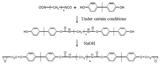
Figure 8.
Toughening modification of phase-change liquid.
The structure of the modified phase-change liquid was characterized by a Fourier transform infrared spectrometer manufactured by Thermo Scientific and the results were analyzed by KnowItAll (R) information system 2018 infrared spectrum analysis software, as shown in Figure 9. A moderate-intensity absorption peak appeared at 3440~3400 cm−1, which was caused by the asymmetric stretching vibration of -NH. The strong absorption peak at 1740~1680 cm−1 was caused by the stretching vibration of C=O. The moderate absorption peak at 1540~1530 cm−1 corresponds to the deformation vibration of -CHN. The moderate absorption peak at 1265~1200 cm−1 was caused by the stretching vibration of N-C-O. The absorption peak at 1090~1040 cm−1 corresponds to the C-O stretching vibration. Through comprehensive analysis, it was concluded that PF was successfully introduced into the molecular structure of the PCL. A moderate-intensity absorption peak appeared at 1280~1230 cm−1, corresponding to the symmetrical stretching vibration of C-O-C. There was a strong absorption peak at 950~815 cm−1, indicating the asymmetric stretching vibration of the C-O-C. The strong absorption peak at 880~805 cm−1 corresponds to the deformation vibration of the C-O-C. Comprehensive analysis showed that the reaction successfully formed epoxy groups.
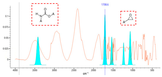
Figure 9.
Infrared spectrum of modified phase-change liquid.
The introduction of the RD and PF successfully modified the PCL, which effectively reduced the liquid viscosity and increased the strength and hardness of the cured product.
Through the modification experiment, it was found that the mass of the RD and PF had a great influence on the strength and hardness of the cured product. Therefore, the influence of different proportions of RD and PF on the mechanical properties and conductivity of the cured product was studied by combining the crushing rate experiment and flow conductivity test.
Crushing rate experimental method
The PF and RD were mixed with 16 base liquid (unmodified PCL) in different proportions (1:1, 1:2, 1:3, 1:4, 5:5, 6:4, 7:3, 8:2, and 9:1) and heated with the CA at 80 °C to form solid materials as shown in Figure 10. Then, the nine samples were tested in the crushing rate experiment and flow conductivity test. The test results are shown in Figure 11 and Figure 12.
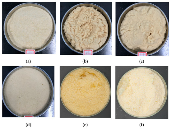
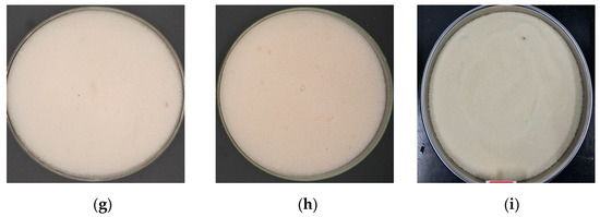
Figure 10.
Solid materials converted from the PCL with different proportions of RD and PF: (a) The ratio of PF to RD is 9:1; (b) The ratio of PF to RD is 8:2; (c) The ratio of PF to RD is 7:3; (d) The ratio of PF to RD is 6:4; (e) The ratio of PF to RD is 5:5; (f) The ratio of PF to RD is 1:1; (g) The ratio of PF to RD is 1:2; (h) The ratio of PF to RD is 1:3; (i) The ratio of PF to RD is 1:4.
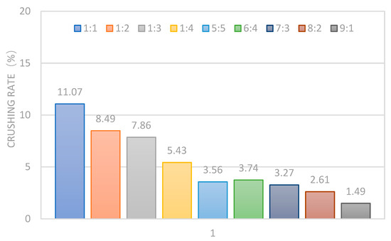
Figure 11.
Experimental results of crushing rate.
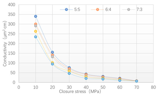
Figure 12.
Fracture conductivity of cured products.
The test results show that the crushing rate of the cured products was over 5% with a small amount of the RD and PF, which cannot meet the requirements of proppant crushing resistance. With the increase in the PF, the crushing rate of the cured products gradually decreased until the PF exceeded 20% and the crushing rate was less than 5%. It was indicated that introducing flexible segments into the main chain and increasing the amount of the RD could significantly strengthen the strength and hardness of the cured products and effectively reduce the crushing rate. In particular, the higher the PF proportion, the lower the crushing rate of the cured product. This indicates that the flexible chain segment containing long aliphatic chain and carbamate group had a significant effect on improving the strength and toughness of the cured products and greatly reduced the crushing under high loading conditions. Table 6 shows a comparison of the crushing rate of the ceramic and new material. It can be seen that the strength and hardness of the new material with different sizes were better than those of the ceramic proppants.

Table 6.
Comparison of crushing rate of ceramic and new material.
Combined with the experimental results of the crushing rate test, five ratios of the RD and PF (1:9, 2:8, 3:7, 4:6, 5:5) were optimized for the conductivity test. The proppant concentration was set to 5 kg/m2 and the closure stress was set to 10, 20, 30, 40, 50, 60, and 70 MPa, respectively.
The results (see Figure 12) show that the fracture conductivity decreased with the decrease in the RD. Through the determination of sample deformation, it was found that the cured products with a low RD content would not crush under high load conditions but had a large deformation. It was indicated that although the increase in the PF content could improve the strength and toughness of the cured products and make them difficult to crush under high load conditions, the hardness could not be fully strengthened, which caused large plastic deformation to lead to a decrease in conductivity. The introduction of the aromatic nucleus of the RD improved the rigidity of the cured products and the epoxy group of the RD reacted with the PCL in the curing reaction to form a three-dimensional spatial network structure and cause the internal structures of the molecules to become closer. Macroscopically, this shows that the cured products had higher hardness and could resist high closure stress without deformation. Finally, the proportion of each component of the phase-change fracturing fluid was designed as RD: PF: PCL = 5:5:16.
Figure 13 and Figure 14 show a comparison of the conductivity of the quartz sand, ceramsite, and new material. It can be seen that the conductivity of the new material was much higher than that of the quartz and ceramsite, with the closure stress under 30 MPa. When the closure stress was over 30 MPa, the new material’s conductivity was less than the ceramsite but higher than the quartz sand. The test results (see Figure 14) also indicated that the ceramsite was more easily breakable under high closure stress, which is consistent with the results of the crushing rate test (see Table 6). The reason for the decrease in the conductivity of the new material is the deformation rather than the breaking.
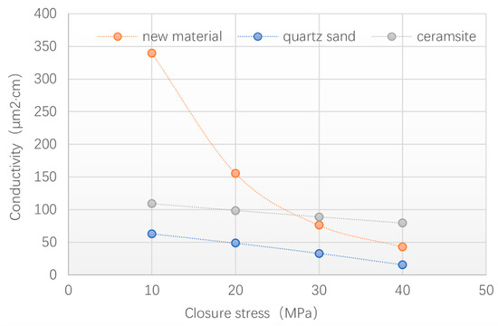
Figure 13.
Comparison of conductivity between quartz sand, ceramsite, and new material.
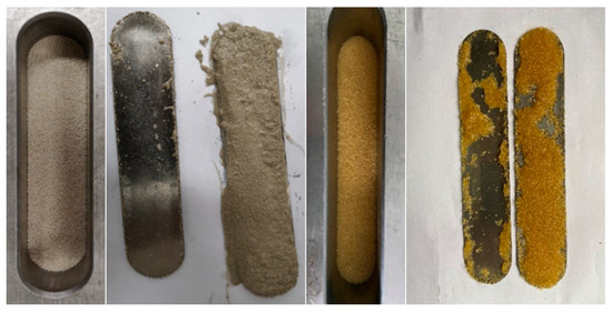
Figure 14.
Fracture conductivity test results.
3. Study on the NPCL
3.1. Design Principle of the NPCL
- (1)
- Immiscible
The PCL and NPCL always occupy their own flow channels in pipelines, wellbore, and fractures, and there will be no dissolution of one phase in another phase. Because the PCL is organic, the NPCL was designed to be inorganic to maintain the immiscibility of the two kinds of fluids.
- (2)
- Easy to inject
The NPCL should have a good flow capacity in pipelines, wellbores, and fractures. As the only liquid requiring flowback, its good fluidity is conducive to that.
- (3)
- Chemical inertness
The NPCL will not react with the formation fluid that causes damage to the reservoir.
- (4)
- The capacity to control the shape, size, and sorting of the PCL
Drawing on the advantages of traditional solid proppants, the proppant with high sphericity will bear less load per unit area under the condition of high closure stress so that the proppant particles will not be broken easily. Therefore, the product after the curing of the phase-change liquid should have high sphericity. The shape of the cured product is determined by the two-phase flow pattern. Through the component design of the NPCL, the PCL can be dispersed in the shape of droplets in a two-phase flow, which finally forms solid particles with high sphericity. The size of the solid particles should be able to change with different construction and formation conditions. By changing the liquid properties of the NPCL, the size of the PCL droplets can be controlled in a two-phase flow to control the size of the solid particles after the phase change.
Under the condition of high closure stress, the better the sorting of the proppant, the smaller the load per unit area and the less likely the proppant to break and deform, meaning it can maintain a high conductivity of fractures for a long time. The sorting of the solid particles is determined by the dispersion and stability of the PCL droplets in the NPCL. Through the modification of the NPCL, the PCL can be stably dispersed in the NPCL, which constructs a stable two-phase flow system of the dispersed phase and continuous phase.
3.2. Screening of the NPCL
According to the design principles, the base fluid of the NPCL is deionized water, whose good fluidity meets the requirement of easy injection, and it is difficult to dissolve and is miscible with organic PCL. Figure 15 shows the mixed state of the PCL and water.
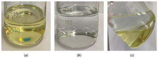
Figure 15.
The mixture of the PCL and water: (a) The PCL; (b) Water; (c) Mixture of PCL and water with a clear boundary.
Based on the molecular interaction theory of the two-phase interfacial layer, the PCL can be dispersed in the NPCL as droplets by changing the interfacial tension between the two phases. The following solutions are proposed.
- (1)
- Reduce interface energy
In a two-phase liquid system, the potential energy of the interface molecules is affected by the phase interface area and interface energy [33]. The dispersion of the PCL in the NCPL results in an increase in the interface area of the two-phase liquid, which leads to an increase in molecular potential energy. However, the interfacial molecules tend to be in a stable state with minimum energy, which leads to the dispersion process being blocked. Only by using surfactants to reduce the interfacial energy can the molecular potential energy be reduced and then promote the formation of the dispersed phase.
Under the same volume conditions, the spherical surface area is the smallest and the dispersed phase will reduce the interface area based on the principle of minimizing the interface potential energy so that the dispersed phase tends to be spherical [34]. Therefore, by adding surfactant into the NPCL, the formation of the dispersed system can be realized and the shape and size of dispersed-phase droplets can be controlled (Figure 16).

Figure 16.
Coalescence process of dispersed droplets.
Therefore, the stable state of the dispersed phase is relative and the coalescence rate plays a major role in the maintenance time of its stable state. Surfactants form a surface film on the two-phase interface through their lipophilic and hydrophilic amphoteric groups, which can stabilize the dispersion state and reduce the rate of coalescence (see Figure 17).

Figure 17.
The schematic diagram of liquid film and interfacial film in a two-phase system.
In addition, polymer and solid particles can also stabilize the interfacial film. Polymers can be adsorbed on the two-phase interface by diffusion and migration. Because of their links, each chain can adsorb on the interface to form an adsorption layer, which will make the boundary film thicker and increase the stability of the interfacial film [35]. Solid particles, whose sizes are much smaller than the PCL droplets and can be wetted by the two-phase liquid, are able to adsorb on the interface layer to thicken the interface film and improve the interface strength (see Figure 18).

Figure 18.
Schematic diagram of the comprehensive action of three substances at the two-phase interface.
According to the above ideas, the NPCL was synthesized and mixed with the PCL. Figure 19a,b show the PCL mixed with the NPCL. It can be observed that the PCL was suspended and dispersed in the NPCL in the form of droplets, with high dispersion and a clear two-phase interface. The dispersion system could maintain a stable state for a long time without coalescence between the droplets.
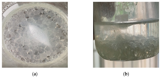
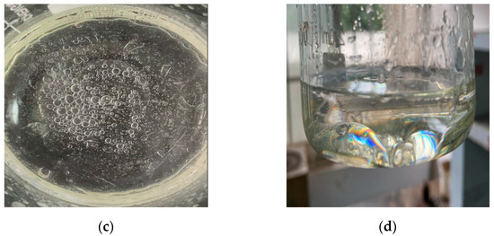
Figure 19.
Dispersion state of the PCL in the NPCL and water: (a) The PCL dispersed in the NPCL in the form of droplets; (b) The PCL maintains the state of the droplets without coalescence for 60 min; (c) Poor dispersion of PCL in water; (d) PCL changes from a dispersed phase to a continuous phase in water in 10 min.
Figure 19c,d show the PCL mixed with water. It can be seen that the droplets formed by the PCL coalesced quickly in water and changed from dispersed-phase to continuous-phase, indicating the poor stability of the dispersed system.
The experiment shows that the addition of polymer, surfactant, and solid particles could form a strong interfacial film on the two-phase interface to ensure the stability of the dispersion system. The formula of the NPCL was determined: water + 1.5% surfactant + 0.01% polymer + 0.5% solid particles.
The NPCL inevitably came into contact with the formation fluid, so it was necessary to evaluate its compatibility with the formation fluid through experiments. Kerosene and diesel oil were used to simulate crude oil, and the simulated formation water was prepared in a laboratory (see Table 7). The formation fluids prepared in the laboratory were mixed with the NPCL at different temperatures (25 °C and 80 °C) to observe whether they would react to form flocs or precipitation. The test results are shown in Figure 20 (for easy observation, the NPCL is dyed blue).

Table 7.
Simulation of formation water composition.

Figure 20.
Experimental results of chemical inertness of the NPCL.
Figure 20a–h show the NPCL (blue liquid) separately mixed with kerosene, diesel oil, and formation water with high or low salinity at different temperatures. The Figure 20a–d are the test results of the NPCL mixed with the kerosene and diesel oil at 25 °C and 80 °C. It can be observed that the interface of the two-phase liquid was clear without miscibility, flocs, and precipitation, which indicates the great compatibility between the NPCL and the crude oil. The Figure 20e–h are the test results of the NPCL mixed with the formation water with high or low salinity at 25 °C and 80 °C. The two kinds of liquid were miscible into each other but no flocs or precipitation were produced, which also proves the great compatibility between the NPCL and the formation water.
4. The Reaction of Fracturing Fluid System under Reservoir Conditions
The process of fracturing fluid distribution, phase change, and propping in induced fractures is influenced by various complex factors during formation (including rock and fluid characteristics, high temperatures and high pressures, fracture complexities, etc.). Therefore, it is necessary to evaluate the phase-change behavior of the new fracturing fluid system under complex formation conditions through experiments to prove the feasibility of its field application.
4.1. Fracturing Fluid Reaction under the Pressure and Fluid of a Reservoir
The PCL and NPCL were mixed at a volume ratio of 1:1, and then the two-phase liquid was mixed with rock powder, crude oil, and formation water. After full stirring and standing for 60 min, the mixed liquid was transferred to the reactor. The reaction temperature was set at 80 °C and the pressure in the reactor was set at 5 MPa, 10 MPa, and 15 MPa, respectively, and the reaction time was set at 10 min. After the reaction, the samples were taken out and the phase-change results were observed and compared with the previous reaction results to verify the adaptability of the liquid system in the formation conditions.
Figure 21a shows that the two-phase liquid was mixed with rock powder, crude oil and formation water. It can be seen that the droplets of the PCL dispersed in the NPCL steadily without coalescence in 60 min, which proves that the complex formation condition would not influence the dispersibility of the two-phase liquid. Figure 21b–d show the cured products that were converted from liquids at 80 °C and in 10 min with different pressure (5 MPa, 10 MPa, 15 MPa). The test results show that the pressure had no effect on the phase-change behavior and the cured products. Figure 21e–g show that the shape and size of the cured products were not affected by the pressure or formation fluid through microstructure observations, which further proved that complex formation conditions would not affect the process and results of the phase change.
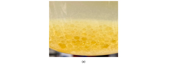
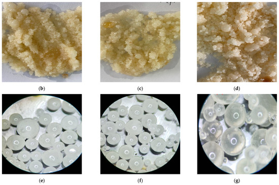
Figure 21.
The process and result of the phase change under complex formation conditions: (a) Two-phase liquid mixed with rock powder, crude oil, and formation water; (b) Solid particles cured in 10 MPa; (c) Solid particles cured in 15 MPa; (d) Solid particles cured in 20 MPa; (e) Microstructure of solid particles cured in 10 MPa; (f) Microstructure of solid particles cured in 15 MPa; (g) Microstructure of solid particles cured in 20 MPa.
4.2. Fracturing Fluid Reaction in Complex Fractures
The PCL and NPCL were placed into two liquid tanks, respectively, at a volume ratio of 1:1. The core that was cut to simulate the complex fractures (see Figure 22) was put into the core holder and heated until the temperature rose to 80 °C. Then, the two-phase liquid was displaced into the core at a constant rate and the confining pressure was increased to simulate a fracture closure. After 10 min, the sample was removed to observe the phase-change results and the distribution of the cured products.

Figure 22.
Core cutting to simulate complex fractures. (the 3 pictures show complex cracks formed by cutting at different angles).
The test results show that the phase-change behavior of the fluid system would not be affected by the complexity of the fractures. In the fractures, the good fluidity of the liquid was reflected at the junction of the fractures and showed that the effective diverting of liquid allowed all fractures to be filled with solid particles converted from liquid, which greatly increased the effective propped area (see Figure 23a). In addition, the high dispersion of the PCL droplets in the NPCL caused the solid particles to fill in the fractures to increase the propping area (see Figure 23b). Figure 23c shows the microstructure of the solid particles converted from the PCL, which proves that the sphericity size of the particles would not be influenced by the formation conditions. Combined with the above experiments, this shows that the fracturing fluid system has good adaptability under reservoir conditions.
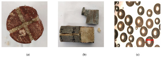
Figure 23.
Simulating phase change in complex fractures: (a) Liquid steers at the junction of fractures; (b) Solid particles completely fill in fractures; (c) The microstructure of solid particles cured in complex fractures.
5. Conclusions
- (1)
- The polymer compounds with a glycidyl ether structure have a close molecular structure, high curing efficiency at high temperatures, low curing shrinkage, and good long-term stability at room temperature. These advantages can just meet the requirements of thermal stimulation response and chemical inertia in the design of the phase-change fracturing fluid. The cured product has a certain strength and hardness, good heat resistance, and chemical stability.
- (2)
- By introducing aromatic groups with a rigid structure to synthesize the reactive diluents, the viscosity of the phase-change liquid is reduced from more than 200 MPa·s to about 80 MPa·s, meeting the injectability requirement. Through the hydroxyl reaction between the PF and phase-change liquid, the flexible segment is introduced to modify the amino formate group and long-chain fat chain in the main chain of the molecule, combined with the rigid structure group introduced in the diluent, and in the curing reaction, the epoxy ring-opening branch in the side chain forms a three-dimensional network structure of the bulk polymer so that the cured product of the phase-change liquid has high strength and hardness, resulting in the long-term stability of the cured product.
- (3)
- The design of a non-phase-change fracturing fluid system is based on the interfacial energy theory. By reducing the interfacial tension between two phases and forming an interfacial film, the phase-change fracturing fluid can keep dispersing and be controlled to be spherical. The optimal formula is water + 1.5% surfactant + 0.01% polymer + 0.5% solid particles.
- (4)
- Through the phase-change experiment of the simulated liquid system under complex formation conditions, it is proved that ① the phase-change behavior and the results of the fracturing fluid system are not affected by complex formation conditions and ② the adaptability of the fracturing fluid in complex fractures is good, which not only reflects the advantage of good liquid fluidity, but also makes it easy to turn at the intersection of joints in the fractures, and the dispersion system composed of a two-phase liquid enables the phase-change solid particles to fill the whole fracture.
Author Contributions
Conceptualization, Y.C.; Data curation, W.C., J.Z. and B.T.; Formal analysis, Y.C.; Investigation, Y.C., Y.S., J.G. and B.T.; Methodology, Y.S.; Resources, J.G.; Supervision, Y.C.; Visualization, J.Y. and F.L.; Writing—original draft, Y.C.; Writing—review & editing, Y.C. All authors have read and agreed to the published version of the manuscript.
Funding
This research was funded by [the key projects supported by the joint fund of the National Natural Science Foundation of China] grant number [U21A20105] And the APC was funded by [PetroChina Southwest Oil & Gas Field Company; the research project on proppant flowback mechanisms and fiber-based proppant flowback control techniques in the process of flowback after fracturing in a horizontal well in Shaximiao in the formation of a tight gas reservoir]. grant number [20220302-24].
Conflicts of Interest
The authors declare no conflict of interest.
References
- Tong, S.; Gao, D. Basic research progress and development suggestions on hydraulic fracturing. Oil Drill. Prod. Technol. 2019, 41, 101–115. [Google Scholar]
- Chen, Y. Experimental Study on a New Type of Self-Propping Fracturing Technology; Southwest Petroleum University: Chengdu, China, 2017. [Google Scholar]
- Zhao, L.; Chen, Y.; Du, J.; Liu, P.; Li, N.; Luo, Z.; Zhang, C.; Huang, F. Experimental Study on a New Type of Self-Propping Fracturing Technology. Energy 2019, 183, 249–261. [Google Scholar] [CrossRef]
- Chang, F.F.; Berger, P.D.; Lee, C.H. In-Situ Formation of Proppant and Highly Permeable Blocks for Hydraulic Fracturing. In Proceedings of the Society of Petroleum Engineers SPE Hydraulic Fracturing Technology Conference, The Woodlands, TX, USA, 3 March 2015. [Google Scholar]
- Faroughi, S.A.; Pruvot, J.; Mcandrew, J. The rheological behavior of energized fluids and foams with application to hydraulic fracturing: Review. J. Pet. Sci. Eng. 2017, 163, 243–263. [Google Scholar] [CrossRef]
- Fernandes, C.; Faroughi, S.A.; Ribeiro, R.; Isabel, A.; McKinley, G.H. Finite volume simulations of particle-laden viscoelastic fluid flows: Application to hydraulic fracture processes. Eng. Comput. 2022, 159, 217–234. [Google Scholar] [CrossRef]
- Sahai, R.; Miskimins, J.L. Laboratory Results of Proppant Transport in Complex Fracture Systems. In Proceedings of the Society of Petroleum Engineers SPE Hydraulic Fracturing Technology Conference, The Woodlands, TX, USA, 4 February 2014. [Google Scholar]
- Weijers, L.; Griffin, L.G.; Sugiyama, H.; Shimamoto, T.; Takada, S.; Chong, K.K.; Wright, C.A.; Terracina, J.M. The First Successful Fracture Treatment Campaign Conducted in Japan: Stimulation Challenges in a Deep, Naturally Fractured Volcanic Rock. In Proceedings of the SPE Annual Technical Conference and Exhibition, San Antonio, TX, USA, 29 September–2 October 2002. [Google Scholar]
- Luo, J.; Zhu, Y.; Guo, Q.; Tan, L.; Zhuang, Y.; Liu, M.; Zhang, C.; Zhu, M.; Xiang, W. Chemical stimulation on the hydraulic properties of artificially fractured granite for enhanced geothermal system. Energy 2018, 142, 754–764. [Google Scholar] [CrossRef]
- Smeal, T.W.; Brownell, G.L. Unsaturated Polyesters. U.S. Patent US5500171 A, 19 March 1996. [Google Scholar]
- Ishida, H.; Rodriguez, Y.C. Catalyzing the curing reaction of a new benzoxazine-based phenolic resin. J. Appl. Polym. Sci. 2010, 58, 1751–1760. [Google Scholar] [CrossRef]
- Kosonen, H.; Valkama, S.; Nykänen, A.; Toivanen, M.; ten Brinke, G.; Ruokolainen, J.; Ikkala, O. Functional Porous Structures Based on the Pyrolysis of Cured Templates of Block Copolymer and Phenolic Resin. Adv. Mater. 2010, 18, 201–205. [Google Scholar] [CrossRef]
- Josifovic, A.; Roberts, J.J.; Corney, J.; Davies, B.; Shipton, Z.K. Reducing the environmental impact of hydraulic fracturing through design optimisation of positive displacement pumps. Energy 2016, 115, 1216–1233. [Google Scholar] [CrossRef]
- Ren, H.; Sun, J.Z.; Wu, B.; Zhou, Q.Y. Synthesis and characterization of a novel epoxy resin containing naphthyl/dicyclopentadiene moieties and its cured polymer. Polymer 2006, 47, 8309–8316. [Google Scholar] [CrossRef]
- Rimdusit, S.; Ishida, H. Development of new class of electronic packaging materials based on ternary systems of benzoxazine, epoxy, and phenolic resins. Polymer 2000, 41, 7941–7949. [Google Scholar] [CrossRef]
- Varley, R.J.; Hodgkin, J.H.; Simon, G.P. Toughening of a trifunctional epoxy system-Part VI. Structure property relationships of the thermoplastic toughened system. Polymer 2001, 42, 3847–3858. [Google Scholar] [CrossRef]
- Wu, C.S. Epoxy resins possessing flame retardant elements from silicon incorporated epoxy compounds cured with phosphorus or nitrogen containing curing agents. Polymer 2002, 43, 4277–4284. [Google Scholar] [CrossRef]
- Nakamura, A.; Inoue, Y. Electrostatic manipulation of enantio-differentiating photo-cyclodimerization of 2-anthracenecarboxylate within γ-cyclodextrin cavity through chemical modification. Inverted product distribution and enhanced enantioselectivity. J. Am. Chem. Soc. 2005, 127, 5338–5339. [Google Scholar] [CrossRef]
- Pan, G.; Du, Z.; Zhang, C.; Li, C.; Yang, X.; Li, H. Synthesis, characterization, and properties of novel novolac epoxy resin containing naphthalene moiety. Polymer 2007, 13, 3686–3693. [Google Scholar] [CrossRef]
- Liu, N.; Li, L.; Wang, L.; Zheng, S. Organic-inorganic poly-benzoxazine copolymers with double decker silsesquioxanes in the main chains: Synthesis and thermally activated ring-opening polymerization behavior. Polymer 2017, 109, 254–265. [Google Scholar] [CrossRef]
- Aditi, S.; Niranjan, K. Renewable resource based thermostable tough hyperbranched epoxy thermosets as sustainable materials. Polym. Degrad. Stab. 2017, 135, 8–17. [Google Scholar]
- Chen, S.; Guo, L.; Du, D.; Rui, J.; Qiu, T.; Ye, J.; Li, X. Waterborne POSS-silane-urethane hybrid polymer and the fluorinated films. Polymer 2016, 103, 27–35. [Google Scholar] [CrossRef]
- Raneesh, K.; Jyotis, P.; Kuruvilla, J. Mechanical, thermal, and viscoelastic response of novel in situ CTBN/POSS/epoxy hybrid composite system. Polym. Compos. 2016, 37, 2109–2120. [Google Scholar]
- Rapheepraew, S.; Vuthichai, E. Synthesis of poly (siloxane/ double-decker silses quioxane) via dehy drocarbonative condensation reaction and its functionalization. Polymer 2016, 86, 113–119. [Google Scholar]
- Chen, L.; Zhao, P.; Xie, H.; Yu, W. Thermal properties of epoxy resin based thermal interfacial materials by filling Ag nanoparticle-decorated graphene nanosheets. Compos. Sci. Technol. 2016, 125, 17–21. [Google Scholar] [CrossRef]
- Liu, Z.; Yuan, L.; Liang, G.; Gu, A. Tough epoxy/cyanate ester resins with improved thermal stability, lower dielectric constant and loss based on unique hyperbranched polysiloxane liquid crystalline. Polym. Adv. Technol. 2015, 26, 1608–1618. [Google Scholar] [CrossRef]
- Xu, J.; Zhang, W.; Jiang, Q.; Mu, J.; Jiang, Z. Synthesis and properties of poly (aryl ether sulfone) incorporating cage and linear organ-osiloxane in the backbones. Polymer 2015, 62, 77–85. [Google Scholar] [CrossRef]
- Vahedi, V.; Pasbakhsh, P.; Chai, S.-P. Toward high performance epoxy/halloysite nanocomposites: New insights based on rheological, curing, and impact properties. Mater. Des. 2015, 68, 42–53. [Google Scholar] [CrossRef]
- Jerzy, J.C.; Elżbieta, L. Modification of epoxy resins with functional silanes, poly-siloxanes, silses-quioxanes, silica and silicates. Prog. Polym. Sci. 2015, 41, 67–121. [Google Scholar]
- Matějka, L.; Kroutilová, I.A.; Lichtenhan, J.D.; Haddad, T.S. Structure ordering and reinforcement in POSS containing hybrids. Eur. Polym. J. 2014, 52, 117–126. [Google Scholar] [CrossRef]
- Zhang, W.; Xu, J.; Li, X.; Song, G.; Mu, J. Preparation, characterization, and properties of poly (aryl ether sulfone) systems with double-decker silses-quioxane in the main chains by reactive blending. J. Polym. Sci. Part A Polym. Chem. 2014, 52, 780–788. [Google Scholar] [CrossRef]
- Ma, S.; Liu, X.; Fan, L.; Jiang, Y.; Cao, L.; Tang, Z.; Zhu, J. Synthesis and Properties of a Bio-Based Epoxy Resin with High Epoxy Value and Low Viscosity. Chem. Sus. Chem. 2014, 7, 555–562. [Google Scholar] [CrossRef]
- Xu, Y.-J.; Chen, L.; Rao, W.-H.; Qi, M.; Guo, D.-M.; Liao, W.; Wang, Y.-Z. Latent curing epoxy system with excellent thermal stability, flame retardance and dielectric property. Chem. Eng. J. 2018, 347, 223–232. [Google Scholar] [CrossRef]
- Yang, S.; Zhang, Q.; Hu, Y.; Ding, G.; Wang, J.; Huo, S.; Zhang, B.; Cheng, J. Synthesis of s-triazine based tri-imidazole derivatives and their application as thermal latent curing agents for epoxy resin. Mater. Lett. 2018, 216, 127–130. [Google Scholar] [CrossRef]
- Fei, X.; Wei, W.; Tang, Y.; Zhu, Y.; Luo, J.; Chen, M.; Liu, X. Simultaneous enhancements in toughness, tensile strength, and thermal properties of epoxy-anhydride thermosets with a carboxyl-terminated hyperbranched polyester. Eur. Polym. J. 2017, 90, 431–441. [Google Scholar] [CrossRef]
Publisher’s Note: MDPI stays neutral with regard to jurisdictional claims in published maps and institutional affiliations. |
© 2022 by the authors. Licensee MDPI, Basel, Switzerland. This article is an open access article distributed under the terms and conditions of the Creative Commons Attribution (CC BY) license (https://creativecommons.org/licenses/by/4.0/).


