Article

Fluidic Thrust, Propulsion, Vector Control of Supersonic Jets by Flow Entrainment and the Coanda Effect

by
Toshihiko Shakouchi
* and
Shunsuke Fukushima
Graduate School of Engineering, Mie University, Tsu 514-8507, Japan
*
Author to whom correspondence should be addressed.
Energies 2022, 15(22), 8513; https://doi.org/10.3390/en15228513
Submission received: 13 October 2022 / Revised: 9 November 2022 / Accepted: 11 November 2022 / Published: 14 November 2022
(This article belongs to the Special Issue Advanced Propulsion System and Thermal Management Technology)

Abstract

:
Thrust, propulsion, vector control of supersonic jets has been applied to jet and rocket engines, ejectors, and other many devices. In general, there are two approaches to this type of control, namely mechanical moving systems and fluidic thrust vector control systems without moving parts, with mechanical moving systems being the most common. However, generally speaking, these systems are very complicated, and more simple methods and devices are desired. In this study, an extremely simple method for the thrust vector control of a supersonic jet by a fluidic Coanda nozzle (FC-nozzle) using the entrainment of the surrounding fluid and Coanda effect is newly proposed. The FC-nozzle consists of a pipe nozzle (Pi-nozzle), spacer, and linearly expanded Coanda nozzle (Co-nozzle) with eight suction pipes (Su-pipes) installed to surround the jet from the Pi-nozzle. The jet from the Pi-nozzle flows straight with the entrainment flow of the surrounding fluid. When some Su-pipes are closed, the pressure between the jet and Co-nozzle wall decreases, and subsequently, the jet deflects to the closed side of the Su-pipe and reattaches to the wall by the Coanda effect. The flow characteristics and deflection characteristics of the supersonic jet from the FC-nozzle are examined by the visualized flow pattern using the Schlieren method and measurements of the velocity distribution. As a result, it is shown that by changing the number of Su-pipes and the locations at which they are closed, the deflection angle and circumferential position of the jet from the Pi-nozzle can be easily controlled.

1. Introduction

Supersonic jets are widely used in the industrial field, in applications such as jet and rocket engines, ejectors, gas-atomization, and many other devices. There has been significant research on the flow characteristics of supersonic under-expanded jet flows (SSU-jets). Donaldson and Snedeker [1] and Kojima and Matsuoka [2] showed the flow structure of the SSU-Jet by measuring the pressure and velocity distributions, and Nourl and Whitelaw [3], Zapryaggaezet et al. [4], and Shakouchi et al. [5,6] (2019, 2020) investigated the flow characteristics of the SSU-Jet by visualizing its flow pattern with the Schlieren method and measuring the pressure and velocity distributions to show the applications of this device. Shadow et al. [7] investigated the spreading rate of the SSU-jet, and Gutmark et al. [8] studied the aeroacoustics of turbulent jets and noise reduction by the chevron nozzle.
The vector control of jet thrust through propulsion is an important research subject. Thrust vector control of the SSU-jet is mainly applied to the altitude control of aircrafts by a jet engine or rocket engine. There are two approaches in general, namely mechanical moving systems and fluidic thrust vector control systems without moving parts, with mechanical moving systems being the most common. Recent typical examples of such systems are the mechanical thrust vector control system of the jet engine in V/STOL aircrafts and rocket engines. However, this is a very complicated system, and simpler methods and devices are desired. Some fluidic systems without moving parts have been proposed. Deere [9] summarized the research on a fluidic thrust vectoring system without moving parts conducted at the NASA Langley Research Center and showed that the throat shifting method provides the most efficient thrust control of the fluidic thrust vectoring methods, but larger thrust vector angles can be obtained with the shock vector control method. Additionally, Páscoa et al. [10] reviewed studies on thrust-vectoring in support of a V/STOL non-moving mechanical propulsion system and introduced the idea that, generally speaking, there are three major systems based on mechanical approaches: the two main bulk streams of the Coanda nozzle and the fluidic control concepts. Fluidic vector thrust control systems with co-flow [11,12], counter-flow [13], a synthetic jet actuator [14,15], shock vector control [16], and sonic throat skewing [17] were introduced and explained. Allen and Smith [18] presented a jet vectoring technique with a novel spray method called Coanda-assisted spray manipulation. The primary jet flows through the center of a rounded collar. The control jet is parallel to the primary jet flow and is adjacent to the convex collar according to known Coanda effect principles and entraining and vectoring of the primary jet, resulting in controllable radial-peripheral directional spraying. However, further research on the thrust vector control of supersonic jets is required. Porhashem et al. [19] and Yan, et al. [20] investigated thrust control by fluidic injection and the flow field characteristics of the SSU-jet. Trancossi et al. [10,21,22,23,24] analyzed the use of the aerial Coanda high-efficiency orienting nozzle (ACHEON) for aircraft propulsion based on the dynamic equilibrium of two jet streams. Conventional fluidic vector control systems without moving parts also require seconday control jets.
In this paper, a new and simple method for the vector control of supersonic jets is proposed. This method involves a fluidic Coanda nozzle (FC-nozzle) and uses the entrainment of the surrounding fluid and the Coanda effect [6]. The FC-nozzle consists of a pipe nozzle (Pi-nozzle), spacer, and linearly expanded Coanda nozzle (Co-nozzle) with eight suction pipes (Su-pipes) installed to surround the jet from the Pi-nozzle. The jet from the Pi-nozzle flows straight with entrainment of the surrounding fluid. When some suction pipes are closed, the pressure between the jet and Co-nozzle wall decreases, and subsequently, the jet deflects to the closed side of the Su-pipe and attaches to the wall by the Coanda effect. The flow characteristics and deflection characteristics of the supersonic jet from the FC-nozzle were investigated by the visualized flow pattern using the Schlieren method and measurements of the velocity distribution. We show that by changing the number of Su-pipes and the locations at which they close, the deflection angle and circumferential position of the jet can be controlled. Furthermore, when there is no fluid to be entrained by the jet, that is, when the surroundings are in a vacuum state, the same type of control can be performed by blowing small amounts of fluid and air from the Su-pipe. This new fluidic thrust vector control system of the supersonic jet is extremely simple compared to other conventional methods that require control with additional devices, such as secondary jets.

2. Experimental Apparatus and Procedure

2.1. Schematics of the Fluidic Coanda Nozzle

Figure 1 shows a schematic diagram of the fluidic Coanda nozzle (FC-nozzle) with no moving parts. The FC-nozzle is an extremely simple system that consists of a pipe nozzle (Pi-nozzle), spacer, and linearly expanded Coanda nozzle (Co-nozzle) with eight suction pipes (Su-pipes) installed to surround the jet from the Pi-nozzle. The diameter of the Pi-nozzle is d0 = 4.0 mm, and the inlet diameter, length, and expansion angle of the Co-nozzle are dic = 5.0 mm, Lc/dis = 2.4, and α = 20°, respectively. On the circumference of the Co-nozzle, eight Su-pipes (n = 8) with diameters of dis = 2.4 mm are installed. The thickness of the spacer is 2.0 mm, and the inlet and outlet diameters are 4.0 and 4.7 mm, respectively. The origin of the coordinates is at the center of the Pi-nozzle exit, and the direction of jet flow is along the x axis. The directions perpendicular to it are the r and r’ axes, as shown in Figure 1.

2.2. Experimental Procedure

The compressed air from the air compressor is supplied to the Pi-nozzle after passing through a dryer and flow control valve, and supersonic jets are issued from the Pi-nozzle or FC-nozzle to the ambient air. A static pressure hole with a diameter of 0.8 mm is installed on the pipe wall connected to the upstream side of the Pi-nozzle, and the pressure there is used as the supply pressure, P0. The supplied pressure changes from P0 = 0.1 to 0.48 MPa. In the current study, most of the experiments were carried out at a supply pressure of P0 = 0.38 MPa, which is sufficient to obtain a supersonic jet. The flow pattern was visualized by the Schlieren method (KATO KOKEN, ss150, Japan) and the image was recorded. The total and static pressures in the flow field were measured with Pitot tubes, and the velocity distribution was obtained using their values, taking into account the effect of air compressibility. The outer and inner diameters of the total pressure tube were 1.0 mm and 0.8 mm, respectively, and the diameter and hole diameter of the static pressure tube were 1.0 mm and 0.6 mm, respectively.

3. Propulsion Vectoring Method

When all 8 Su-pipes are opened, the jet entrains the surrounding fluid from the Su-pipes and around the jet, and flows downstream along the nozzle axis, as shown in Figure 1a. On the other hand, when some Su-pipes are closed, the jet cannot entrain surrounding fluid from their sides, and subsequently, the pressure between the outer edge of the jet and the wall of the Co-nozzle decreases, and then, the jet deflects to the closed side of the Su-pipe by the Coanda effect, as shown in Figure 1b. Therefore, arbitrary circumferential vector control of the jet from the Pi-nozzle can be performed by changing the number of Su-pipes and the locations at which they are closed. If these Su-pipes are opened and closed using a solenoid valve and a computer control system, dynamic thrust vector control becomes possible.
There does not necessarily have to be eight Su-pipes. All that is necessary is to block part of the circumference of the jet from the Pi-nozzle.

4. Results and Discussion

First, the flow characteristics of under-expanded supersonic jet from the Pi-nozzle are investigated using the visualized flow pattern and measurements of the velocity distribution.

4.1. Jet Flow from the Pi-Nozzle

4.1.1. Visualized Flow Pattern

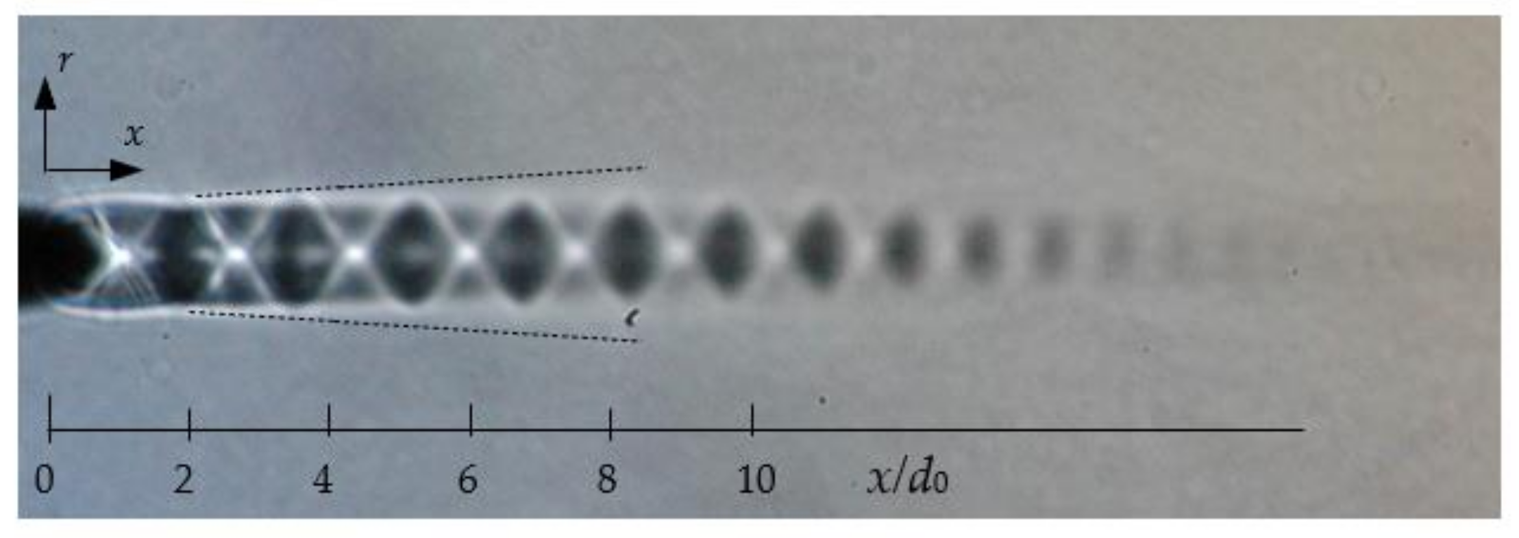
The visualized flow pattern of the under-expanded supersonic jet from the pipe nozzle (Pi-nozzle) (Figure 1) produced by the Schlieren method is shown in Figure 2. The supplied pressure is P0 = 0.38 MPa. The black and white colored areas in the jet are compression and expansion regions, respectively, and white colored x shaped pseudo-shock waves can be seen in the shock cell. The dotted lines in the figure indicate the approximate jet boundary derived from the measurements of the cross sectional velocity distributions at x/d0 = 2.1, 4.2, 5.4, 8.3. The jet boundary is at the position of r at u/uc = 0.1. The jet expands at the nozzle exit and the jet width increases almost linearly in the range of x/d0 > 3.0.

4.1.2. Jet Centerline Velocity Distribution

The jet centerline velocity uc is indicated by a circle in Figure 5 shown later. This was obtained from the measurements of the total and static pressure distributions. The jet repeatedly expands and compresses and reaches the maximum value at x/d0 = 5.8. In the downstream area of x/d0 > 12.5, uc decay occurs slowly.

4.2. Jet Flow from the FC-Nozzle

Next, the flow characteristics and vector control of the jet issued from the FC-nozzle with the Co-nozzle were investigated using the visualized flow pattern and measurements of the velocity distribution.

4.2.1. Visualized Flow Pattern

Figure 3a shows the visualized flow pattern of the FC-jet issued from the FC-nozzle when all the Su-pipes are opened, 0-close. The supplied pressure is P0 = 0.38 MPa. The jet flows straight to the downstream entraining the surrounding fluid from the Su-pipes and around the jet (Figure 1a). The shock waves can be seen in the jet, and the white and black colored areas from the nozzle exit represent the expansion and compression shock waves, respectively. However, the FC-jet with 0-close decays faster than the Pi-jet shown in Figure 2, because the entrainment of surrounding fluid is suppressed by the Co-nozzle.
Figure 3d shows the case in which Su-pipes ①–③ and ⑥–⑧ are closed (6-closed). The entrainment from those Su-pipes is prevented, and the pressure between the outer edge of the jet from the Pi-nozzle and the wall of the Co-nozzle decreases. Consequently, the jet deflects and reattaches to the wall of the Co-nozzle by the Coanda effect. The deflection angle is β = 10°, which is the same as the opening angle of the Co-nozzle.
Figure 3b,c show the 2- and 4-closed cases, respectively. Figure 3e shows the 8-closed case, where the jet flows straight to the downstream area; however, since the jet cannot entrain the surrounding fluid from the Su-pipe and the flow resistance of the nozzle increases, the jet velocity is slower than those of the others.

4.2.2. Deflection Angle, β

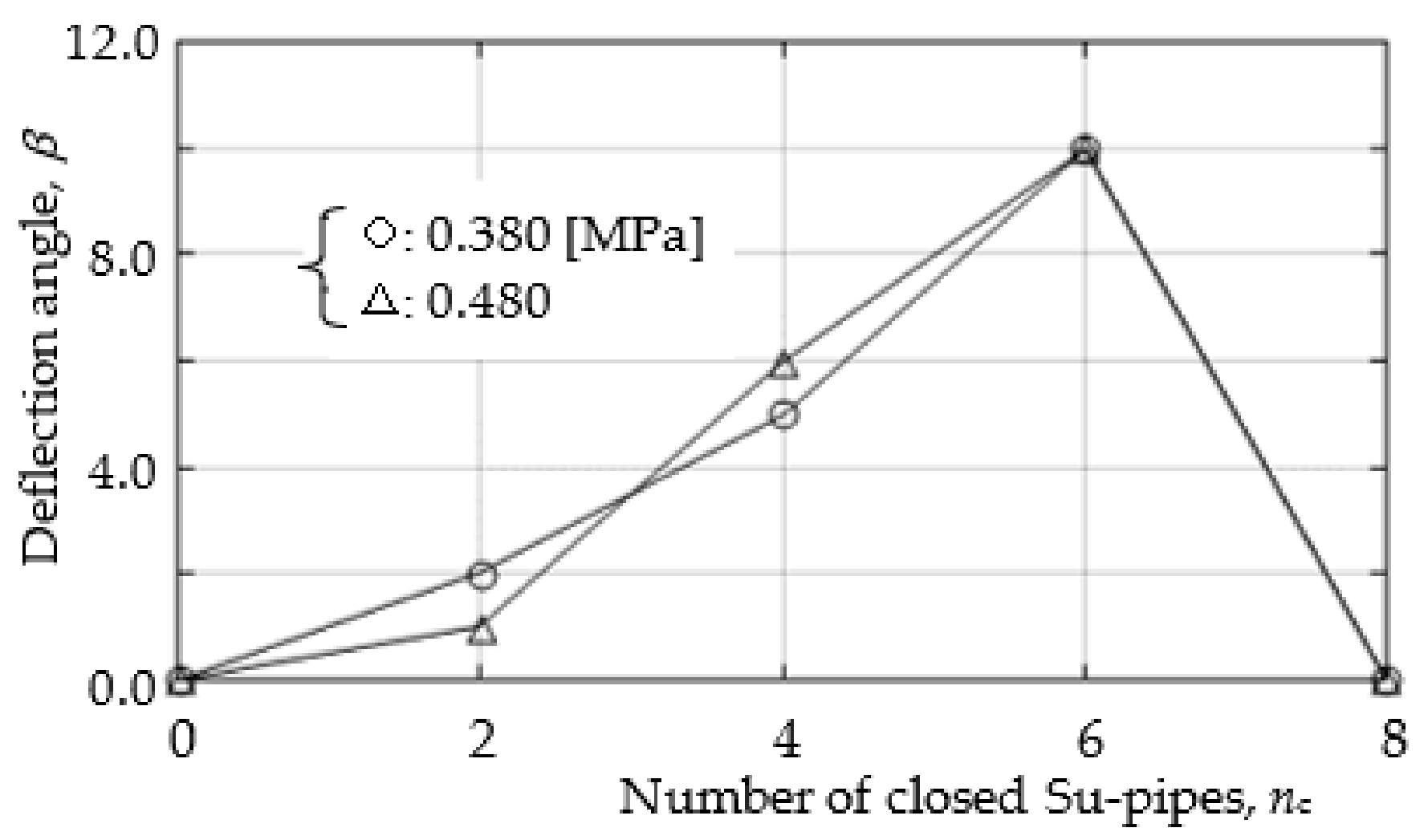
Figure 4 shows the deflection angle, β, and the number of closed Su-pipes, nc. β increases as nc increases and has a maximum value of β = 10° at nc = 6. In the figure, the results for the greater supply pressure, P0 = 0.46 MPa, are also shown for reference, and both values are approximately the same. By changing the number of Su-pipes and the locations at which the Su-pipes close, the deflection angle and circumferential position of the jet can be controlled.

4.2.3. Practical Operation

In practical applications, it is conceivable to use a computer-controlled solenoid valve to change the number of Su-pipes and the locations at which they close.

4.3. Velocity Distribution

In order to clarify the flow characteristics of the straight and deflected jets, the jet center line and cross-sectional velocity distributions were measured.

4.3.1. Jet Centerline Velocity Distribution
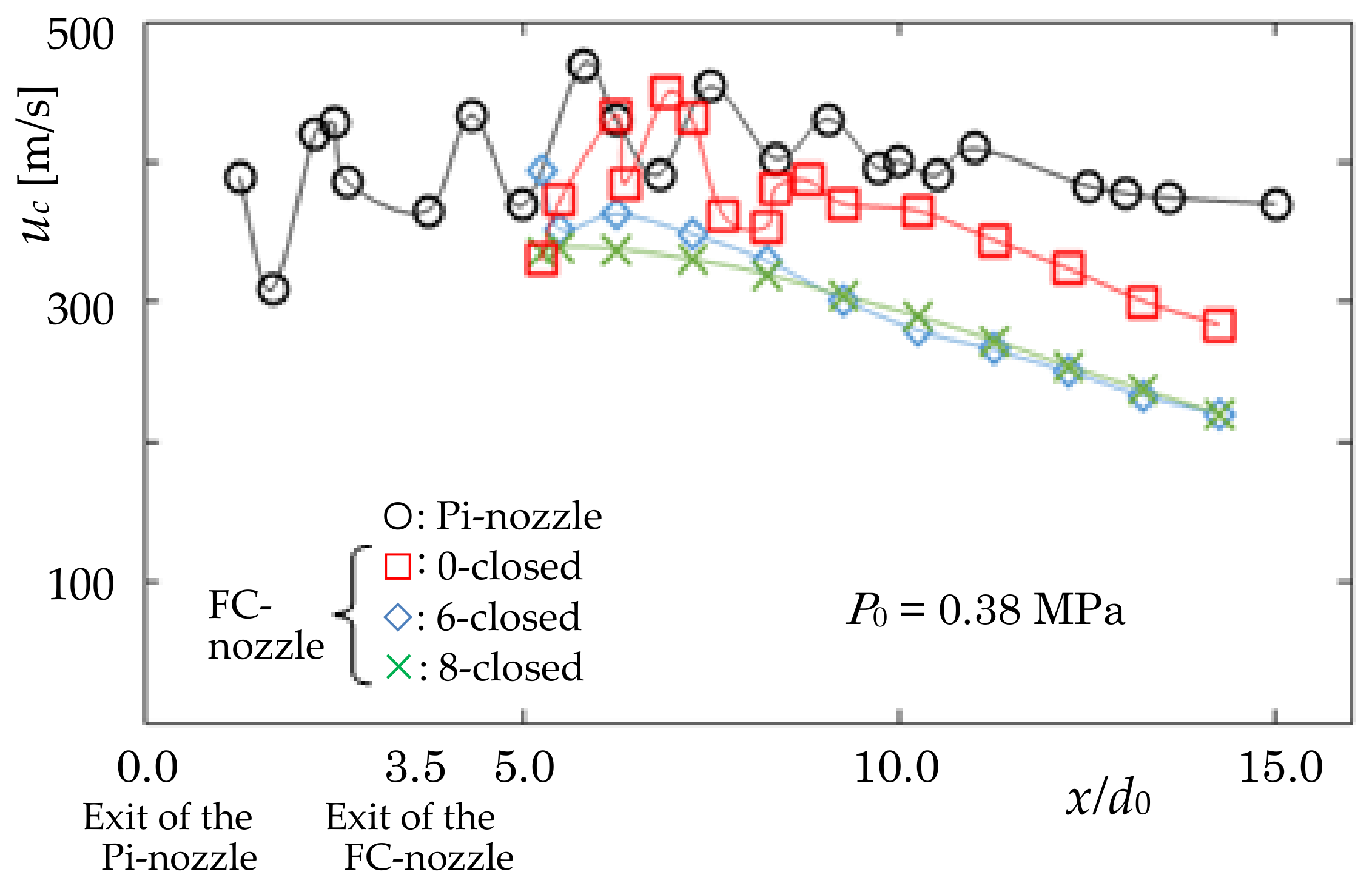
Figure 5 shows the centerline velocity distribution of the jets uc at P0 = 0.38 MPa. The velocity was obtained by measurements of the total and static pressure distributions with consideration of the compressibility of the fluid, air. In Figure 5, the position of the nozzle exit of the FC-nozzle is x/d0 = 3.5 (the distance in the x-direction from the exit of the FC-nozzle: s/d0 = 0.0). The Pi-jet flows downstream with a large fluctuation of uc, corresponding to the expansion and compression shock waves of the flow, and uc decreases monotonously in the region of x/d0 > 11. In the 0-closed case, uc is smaller than in the Pi-jet due to the large flow resistance of the Co-nozzle. Moreover, as the number of closed Su-pipes increases, the entrainment of the surrounding fluid from the Su-pipe decreases. The uc of the 8-closed condition decreases monotonously, and it approximately equals that of the 6-closed case in the region of x/d0 > 8.
Figure 5. Jet centerline velocity distribution, uc (0-, 6-, 8-closed jets and Pi-jet, P0 = 0.380 MPa): The uc of the 0-closed nozzle is smaller than that of the Pi-jet owing to the large flow resistance of the Co-nozzle.
Energies 15 08513 g005

4.3.2. Cross-Sectional Pressure and Velocity Distributions

1.
Total Pressure Distribution
Figure 6a shows the total pressure distributions, Pt /P0, in the cross-section at x/d0 = 4.2 (s/d0 = 0.7) for the 0-closed condition as an example. The jet of the 0-closed case flow straight to the downstream area, and the profile is axisymmetric and dented at the center. In comparison, the 6-closed case has a small maximum total pressure because of the large flow resistance of the Co-nozzle and the asymmetric profile.
Figure 6b,c are the results at x/d0 = 5.4, 8.3, respectively. The profile at x/d0 = 8.3 for the 0-closed case is axisymmetric, and the maximum value is approximately twice that of the 6-closed case.
2.
Static Pressure Distribution
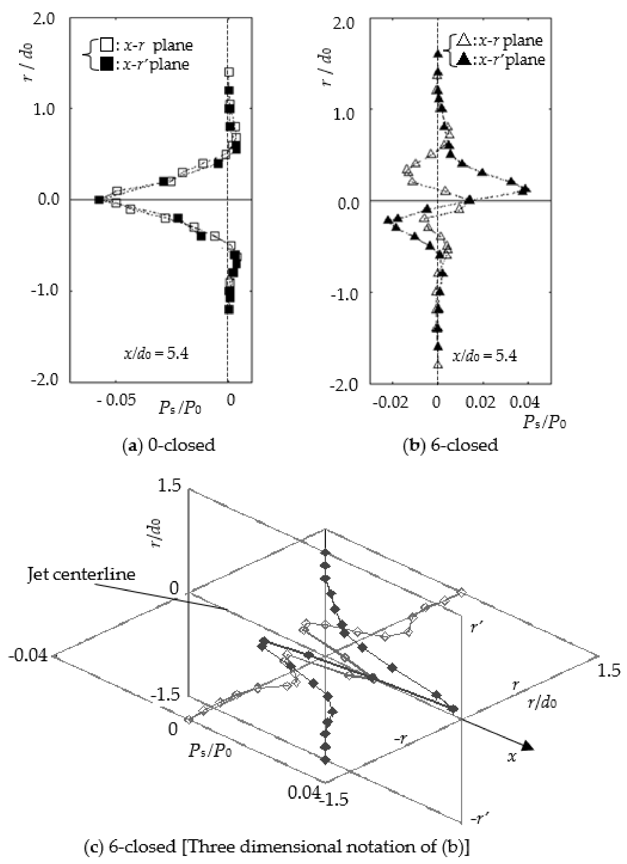
Figure 7a shows the static pressure distribution, Ps/P0, in the cross section at x/d0 = 5.4 (s/d0 = 1.9) for the 0-closed case. The profile is dented at the center by the expansion shock wave [2].
Figure 7b shows the results for the 6-closed case and Figure 7c is a three-dimensional drawing of Figure 7b. The profile is asymmetric, because the jet deflects and reattaches to the wall of the Co-nozzle, and consequently, the shape of the jet deforms. The jet reattaches to the wall of the Co-nozzle at the +r’-axis side and entrains the surrounding fluid from the –r’-axis side because of negative pressure.
3.
Sectional Velocity Distribution
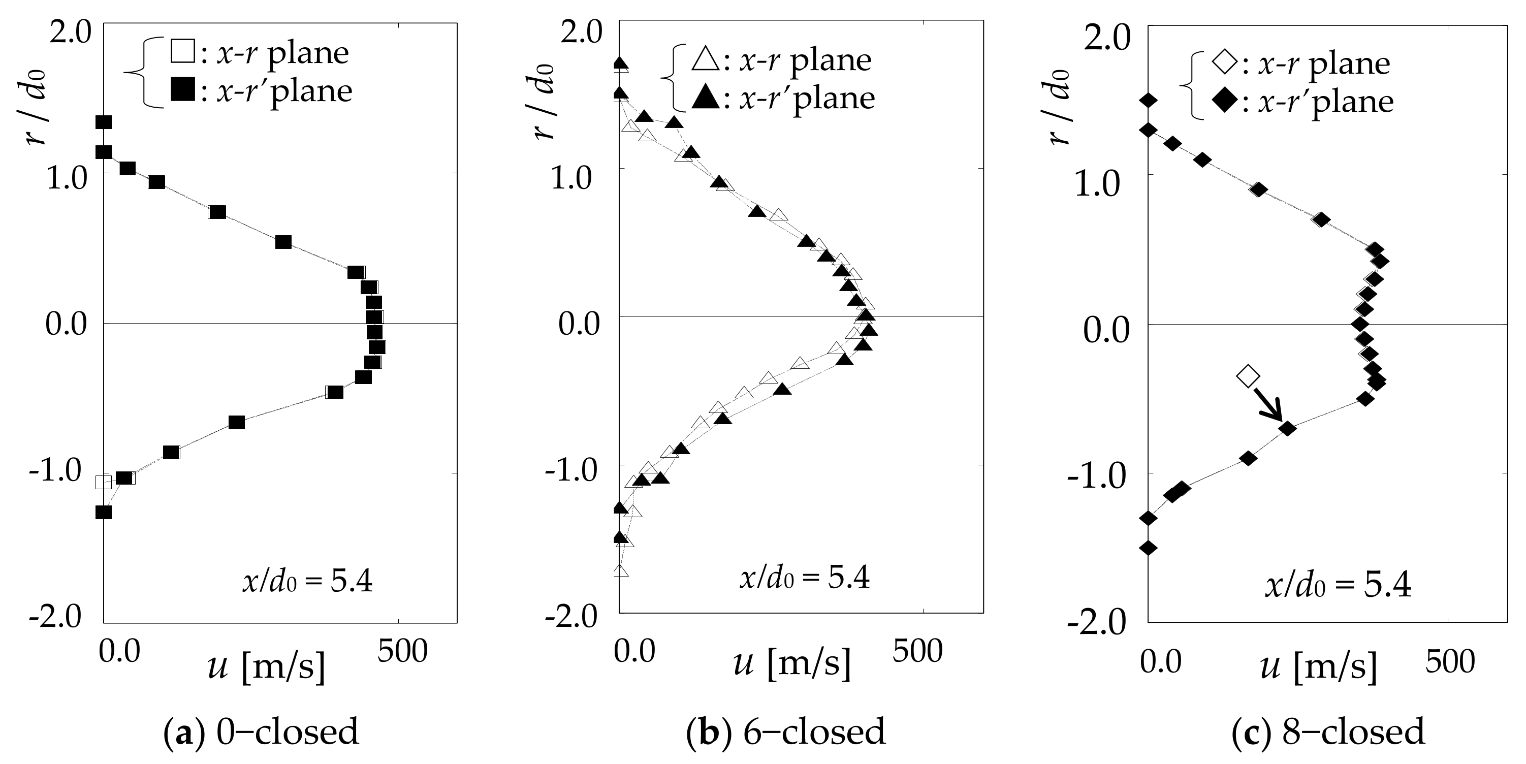
Figure 8 shows the velocity distribution obtained with the total and static pressure measurements under the consideration of the compressibility of the fluid in the cross-section at x/d0 = 5.4. The velocity profile of the 6–closed case is smaller than that of the 0-closed case because of a larger flow resistance of the Co-nozzle.
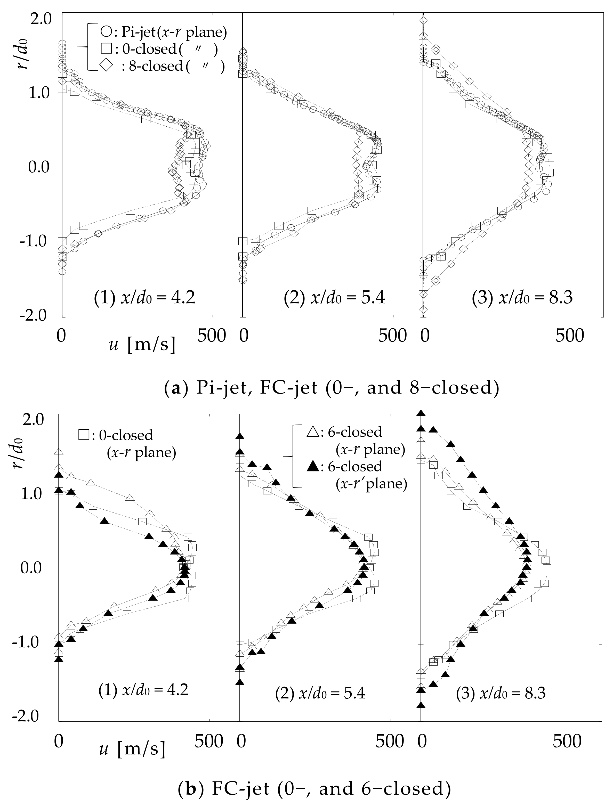
Figure 9 shows the velocity distribution in the cross section at x/d0 = 4.2, 5.4, and 8.3 for the 0-, 6-, and 8-closed cases. In Figure 9a, the results for the Pi-jet are also shown for reference. The velocity was obtained by taking the static pressure, Ps, as the ambient pressure, i.e., the atmospheric pressure, Pa. The velocity distribution of the 0-closed case at x/d0 = 5.4 and the results shown in Figure 8a are approximately the same, because the static pressure is much smaller than the total pressure, as shown in Figure 6 and Figure 7. In this case, it seems that the velocity may be obtained by using Ps as Pa.
The maximum velocity of the 0-closed case is approximately equal to that of the Pi-jet and larger than that of the 8-closed case, because the flow resistance of the Co-nozzle for the 8-closed case is greater than those of the others.
The flow characteristics of the straight and deflected flows were made clear by the velocity measurements.

4.3.3. Thrust, Approximate Estimation

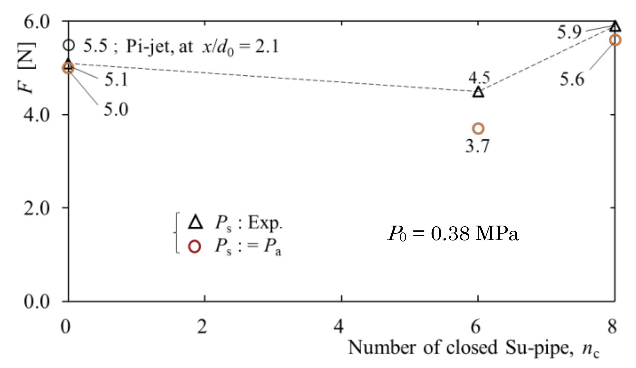
The deflected jet has an asymmetric velocity profile, as shown in Figure 9b. The thrust, F, of the jet was calculated by the following equation under the assumption that the cross-section of the jet is approximately circular. At this time, the mean values of the x-r and x-r’ planes were taken for the asymmetric velocity distribution. The density, ρ, was estimated approximately using the equation of the state of gas.
F   =   0 ρ u 2 2 π r d r   +   P e     P a   A e
Figure 10 shows the thrust, F, of the FC-jet calculated at x/d0 = 5.4 (s/d0 = 1.9) for P0 = 0.38 MPa. The F of the 6-closed case is smaller than that of the 0-closed case because the entrainment from the surroundings of the 6-closed case is restricted. On the other hand, the F of the 8-closed case is larger than that of the 0-closed case, and this seems to be due to the jet approaching proper expansion. The differences in the F value when the static pressure is atmospheric pressure, and when the measurements were used, the value was ± 6 % for the 0- and 8-closed cases and ±29% for the 6-closed case, respectively. The large difference for the 6-closed case is probably due to the deformation and asymmetry of the jet’s shape. We showed that by changing the number of the Su-pipes and the locations at which they close, the deflection angle and circumferential position of the jet can be controlled, and consequently, the thrust of the supersonic jet can be controlled by a new simple fluidic vector control system.

4.3.4. Thrust Vectoring by Sub Jets

When there is no fluid to be entrained by the jet, that is, when the surrounding area is in a vacuum state, the same control can be performed by blowing a small amount of fluid from the Su-pipe.
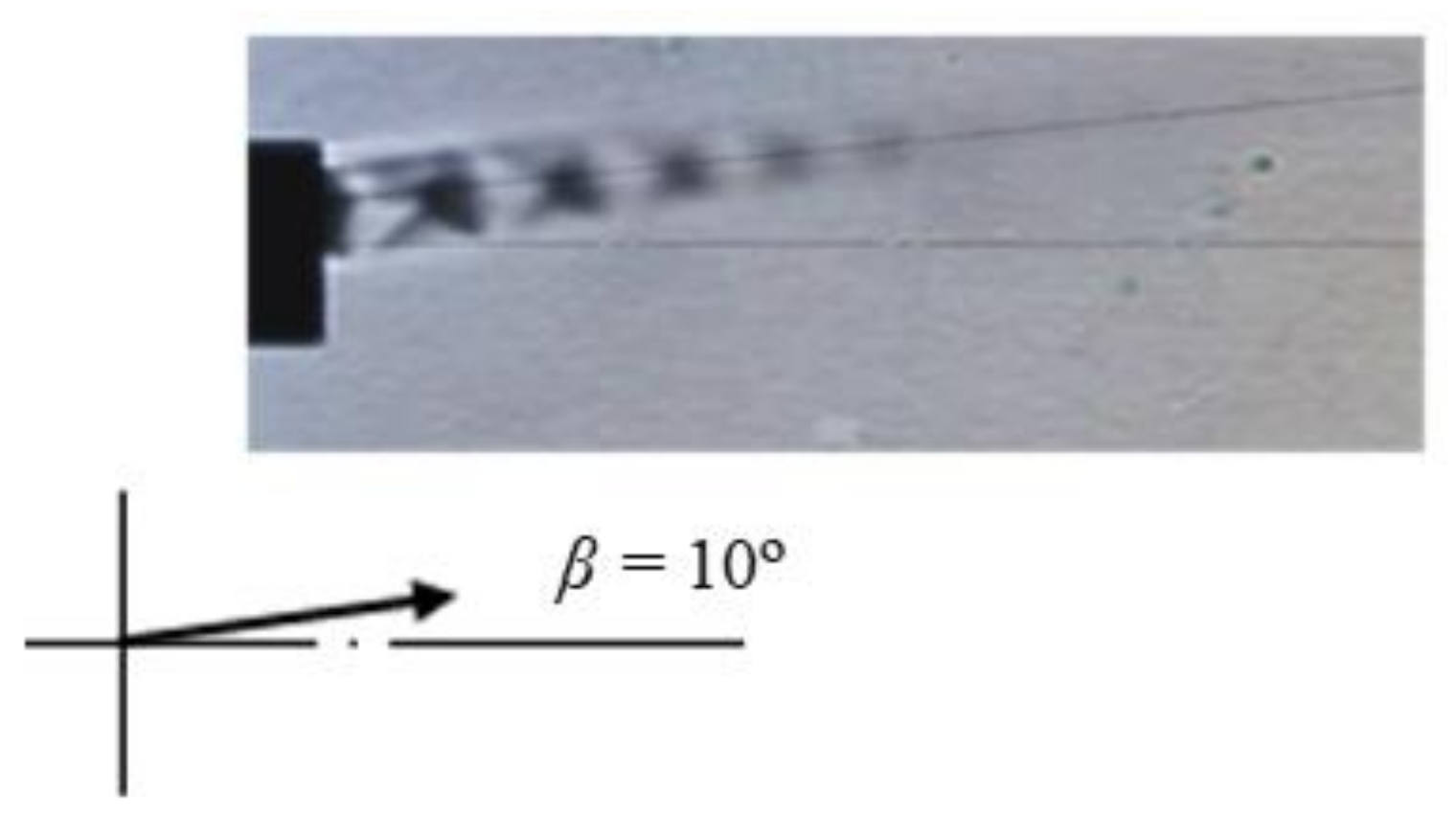
Using the same nozzle, the FC-nozzle, to blow sub-jets from the two Su-pipes (2-blow) at a small portion of the total flow rate of Qc = 10 [L/min], the jet supplied with P0 = 0.38 MPa is deflected, similar to the result shown in Figure 3d, at an angle of β = 10° to the side that does not blow out, because the pressure on the blowing side increases. Qc = 10 [L/min] is about 1.8% of the main jet flow estimated under the standard state.
Figure 11 shows the visualized flow pattern, and the number of Su-pipes blowing is nb = 2 from ④ and ⑤ in Figure 3 with all remaining Su-pipes are closed.
1.
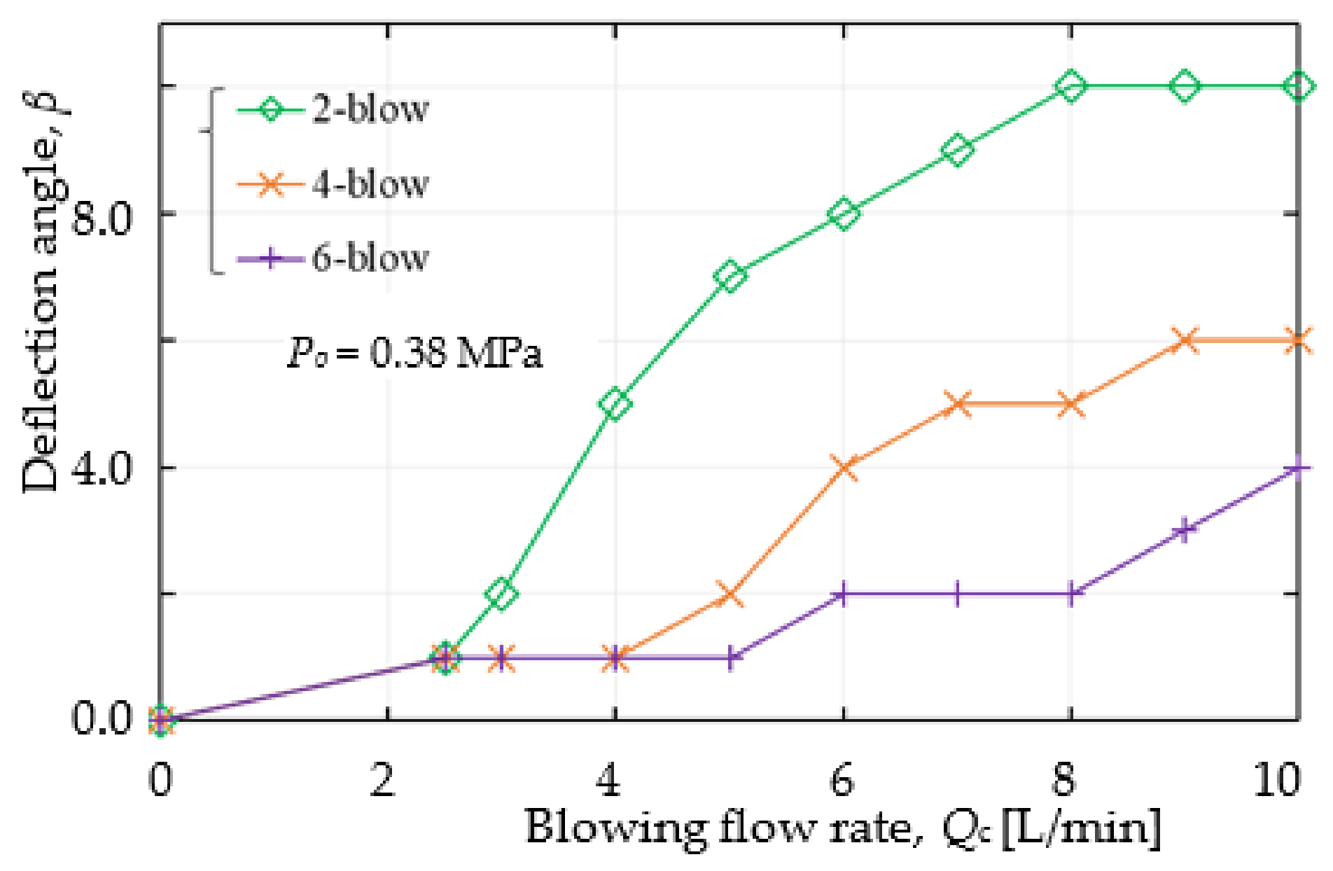
Effect of the Blowing Flow Rate Qc on the Deflection Angle β Figure 12 shows the relationship between β and Qc when air is blown from Su-pipes 2, 4, and 6. β increases as Qc increases, and β also increases as the number of blowing nozzles, nb, decreases, because by increasing nb, the blowing flow rate per Su-pipe decreases. The deflection angle has a maximum value of β = 10° at nb = 2 and Qc = 8 [L/min].
2.
Effect of the Number of Blowing Nozzles, nb, on the Deflection Angle β
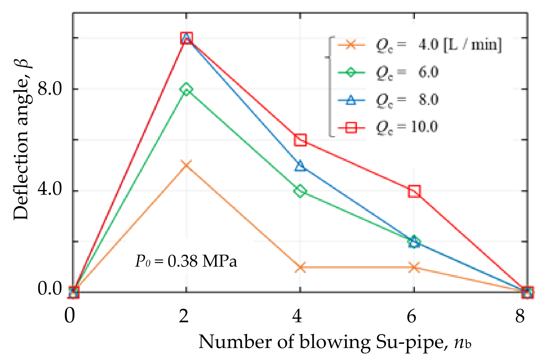
Figure 13 indicates the relation between β and nb. The deflection angle has a maximum value of β = 10° at nb = 2, and in the 4−, 6−, and 8−blow cases, the deflected angles are 6°, 4°, and 0°, respectively.
It is considered that the deflection angle β can be increased by increasing the opening angle α of the FC-nozzle. However, investigation of the characteristics of the shape of the FC-nozzle, such as the optimal length and α, is a subject for further study.

5. Conclusions

In this paper, thrust vector control of the supersonic under-expanded jet by a non-moving system was examined, and a new and simple vector control method for supersonic jets was proposed. The method uses a fluidic Coanda nozzle (FC-nozzle) entrain the surrounding fluid and the Coanda effect. The FC-nozzle consists of a pipe nozzle (Pi-nozzle), spacer, and linearly expanded Coanda nozzle (Co-nozzle) with eight suction pipes (Su-pipes). The jet from the Pi-nozzle flows straight with entrainment of the surrounding fluid from the Su-pipes and around the jet. When some Su-pipes are closed, the pressure between the jet and Co-nozzle wall decreases, and subsequently, the jet deflects to the closed side of the Su-pipe and attaches to the wall of the Co-nozzle by the Coanda effect. The flow characteristics and deflection characteristics of the supersonic jet issued from the FC-nozzle were assessed by the visualized flow pattern using the Schlieren method and measurements of the velocity distribution.
(1)
By changing the number of the Su-pipes and the locations at which the Su-pipes close, the deflection angle and circumferential position of the jet can be controlled. That is, vector control of the thrust of the supersonic jet can be performed with this new and simple method and apparatus.
(2)
This new fluidic thrust vector control method for supersonic jets is extremely simple compared to other conventional methods that require control with additional devices, such as secondary jets.
(3)
In practical applications, it is conceivable that a computer-controlled solenoid valve could be used to change the number of Su-pipes and the locations at which they close.
(4)
When there is no fluid to be entrained by the jet, that is, when the surroundings are in a vacuum state, the same type of control can be gained by blowing a small amountof fluid from the Su-pipe.
The effects of the expansion angle and length of the Co-nozzle on jet deflection are issues for further study.

Author Contributions

Conceptualization, T.S.; methodology, T.S.; software, T.S. and S.F.; validation, T.S. and S.F.; formal analysis, T.S.; investigation, T.S.; resources, T.S.; data curation, T.S. and S.F.; writing—original draft preparation, T.S.; writing—review and editing, T.S. and S.F.; visualization, T.S.; supervision, T.S.; project administration, T.S. All authors have read and agreed to the published version of the manuscript.

Funding

This research received no external funding.

Informed Consent Statement

Not applicable.

Data Availability Statement

Not applicable.

Acknowledgments

The authors would like to thank K. Tsujimoto, T. Ando and M. Takahashi for their valuable discussions and Messrs. T. Tanoue and K. Hinaga for their cooperation with the experiments.

Conflicts of Interest

The authors declare no conflict of interest.

Nomenclature

Aeexit area of the Pi-nozzle
dicdiameter of the Su-pipe
disinlet diameter of the Co-nozzle
d0diameter of the Pi-nozzle
Fthrust
Lclength of the Co-nozzle
nnumber of Su-pipes
nbnumber of blowing Su-pipes
ncnumber of closing Su-pipes
Paambient pressure (atmospheric pressure)
Peexit pressure of the Pi-nozzle
Psstatic pressure
Pttotal pressure
P0supply pressure
Qctotal blowing flow rate
r, r’perpendicular directions of the x-axis, respectively (Figure 1)
sdistance in the x-direction from the exit of the FC-nozzle
uvelocity in the x direction
ucjet centerline velocity
xdirection of jet flow (Figure 1)
αexpansion angle of Co-nozzle
βjet deflection angle
ρdensity of fluid (air)
Abbreviations
Co-nozzleCoanda nozzle
FC-nozzlefluidic Coanda nozzle
Pi-nozzlepipe nozzle
SSU-jetsupersonic under-expanded jet flow
Su-pipesuction pipe

References

  1. Donaldson, S.D.; Snedeker, R.S. Abst: Under-Expanded Jet. 1971. Available online: http://www.kbwiki.ercoftac.org/w/index.pkp/Abstr:Under-expanded_jet (accessed on 1 March 2019).
  2. Kojima, T.; Matsuoka, Y. Study of an under-expanded sonic jet (1st Report, On the mechanism of pseudo-shock waves and pressure and velocity in jets). Trans. Jpn. Soc. Mech. Eng. JSME 1987, 259, 190–191. (In Japanese) [Google Scholar]
  3. Nourl, J.M.; Whitelaw, J.H. Flow characteristics of an under-expanded jet and its application to the study of droplet breakup. Exp. Fluids 1996, 21, 243–247. [Google Scholar] [CrossRef]
  4. Zapryagaez, V.I.; Kiselev, N.P.; Pivovarov, A.A. Gas dynamic structure of an axisymmetric supersonic under-expanded jet. Fluid Dyn. 2015, 50, 95–107. [Google Scholar]
  5. Shakouchi, T.; Tanoue, T.; Tsujimoto, K.; Ando, T. Flow characteristics of sub- and supersonic jets issued from orifice and notched orifice nozzles, and application to ejector. J. Fluid Sci. Technol. JSME 2019, 14, 1–12. [Google Scholar] [CrossRef] [Green Version]
  6. Shakouchi, T. Passive flow control of jets. J. Mech. Eng. Rev. JSME 2020, 17, 1–18. [Google Scholar] [CrossRef] [Green Version]
  7. Shadow, K.C.; Gutmark, E.; Wilson, W.J. Compressible spreading rates of supersonic coaxial jets. Exp. Fluids 1990, 10, 161–167. [Google Scholar] [CrossRef]
  8. Gutmark, E.J.; Callender, B.W.; Martens, S. Aeroacoustics of Turbulent Jets: Flow Structure, Noise Sources, and Control. JSME Int. J. Ser. Fluid Therm. Eng. 2006, 49, 1078–1085. [Google Scholar] [CrossRef]
  9. Deere, K.A. Summary of fluidic thrust vectoring research conducted at NASA Langley Research Center. In Proceedings of the 21st AIAA Applied Aerodynamics Conference, Orlando, FL, USA, 1 January 2003; AIAA-2003-3800. pp. 1–18. [Google Scholar]
  10. Pascoa, L.; Dumas, A.; Trancossi, M.; Stewart, P.; Vucinic, D. A review of thrust vectoring in support of V/STOL non-moving mechanical propulsion system. Cent. Eur. J. Phys. 2013, 3, 374–388. [Google Scholar] [CrossRef] [Green Version]
  11. Heo, J.Y.; Too, K.H.; Lee, Y.; Sung, H.G.; Cho, S.H.; Jeon, Y.J. Fluidic thrust vector control of supersonic jet using co-flow injection. In Proceedings of the 45th AIAA/ASME/SAE/ASEE Joint Propulsion Conference Exhibit, Denver, CO, USA, 2–5 August 2009; AIAA 2009-517. pp. 1–2. [Google Scholar]
  12. Dumitrache, A.; Frunzulica, F.; Preotu, O.; Ionescu, T. Thrust and jet directional control using the Coanda effect. IN-CAS Bull. 2018, 10, 199–205. [Google Scholar] [CrossRef]
  13. Wu, K.; Kim, H.D.; Jin, Y. Fluidic thrust vector control based on counter-flow concept. Proc. Inst. Mech. Eng. Part G J. Aerosp. Eng. 2018, 233, 1412–1422. [Google Scholar] [CrossRef]
  14. Trancossi, M.; Dumas, A. Coanda Synthetic Jet Deflection Apparatus and Control; No. 2011-01-2590; SAE International: Warrendale, PA, USA, 2011. [Google Scholar] [CrossRef] [Green Version]
  15. Liu, J.F.; Luo, Z.B.; Deng, X.; Zhao, Z.J.; Li, S.Q.; Liu, Q.; Zhu, Y.X. Dual Synthetic jets actuator and its applications—Part II: Novel fluidic thrust-vectoring method based on dual synthetic jets actuator. Actuators 2022, 11, 209. [Google Scholar] [CrossRef]
  16. Resta, E.; Malsilio, R.; Ferlauto, M. Thrust vectoring of a fixed axisymmetric supersonic nozzle using the shock-vector control method. Fluids 2021, 6, 441. [Google Scholar] [CrossRef]
  17. Miller, R.; Yagle, P.J.; Hamstra, J.W. Fluidic throat skewing for thrust vectoring in fixed-geometry nozzles. In Proceedings of the 37th Aerospace Sciences Meeting and Exhibit, Reno, NV, USA, 11–14 January 1999; p. AIAA-99-0365. [Google Scholar] [CrossRef]
  18. Allen, D.; Smith, B.L. Axisymmetric Coanda-assisted vectoring. Exp. Fluids 2009, 46, 55–64. [Google Scholar] [CrossRef] [Green Version]
  19. Pourhashem, H.; Kumar, S.; Kalkhoran, I.M. Flow field characteristics of a supersonic jet influenced by downstream micro jet fluidic injection. Aerosp. Sci. Technol. AESCTE 2019, 93, 1–15. [Google Scholar] [CrossRef] [Green Version]
  20. Yan, D.; Wei, Z.; Xie, K.; Wang, N. Simulation of thrust control by fluidic injection and pintle in a solid rocket motor. Aerosp. Sci. Technol. AESCTE 2020, 99, 1–10. [Google Scholar] [CrossRef]
  21. Trancossi, M. An overview of Scientific and Technical Literature on Coanda Effect Applied to Nozzles. SAE Tech. Pap. 2011, 2011, 2591. [Google Scholar] [CrossRef]
  22. Trancossi, M.; Dumas, A. ACHEON: Aerial Coanda High Efficiency Orienting-Jet Nozzle; No. 2011-01-2737; SAE International: Warrendale, PA, USA, 2011. [Google Scholar] [CrossRef]
  23. Trancossi, M.; Madonia, M.; Dumas, A.; Angeli, D.; Bingham, C.; Sumanta Das, S.; Grimaccia, F.; Marques, J.P.; Porreca, E.; Smith, T.; et al. A new aircraft architecture based on the ACHEON Coanda nozzle: Flight model and energy evaluation. Eur. Transp. Res. Rev. 2016, 8, 1–21. [Google Scholar] [CrossRef] [Green Version]
  24. Trancossi, M.; Stewart, J.; Maharshi, S.; Angeli, D. Mathematical model of a constructal Coanda effect nozzle. J. Appl. Fluid Mech. 2016, 9, 2813–2822. [Google Scholar] [CrossRef]
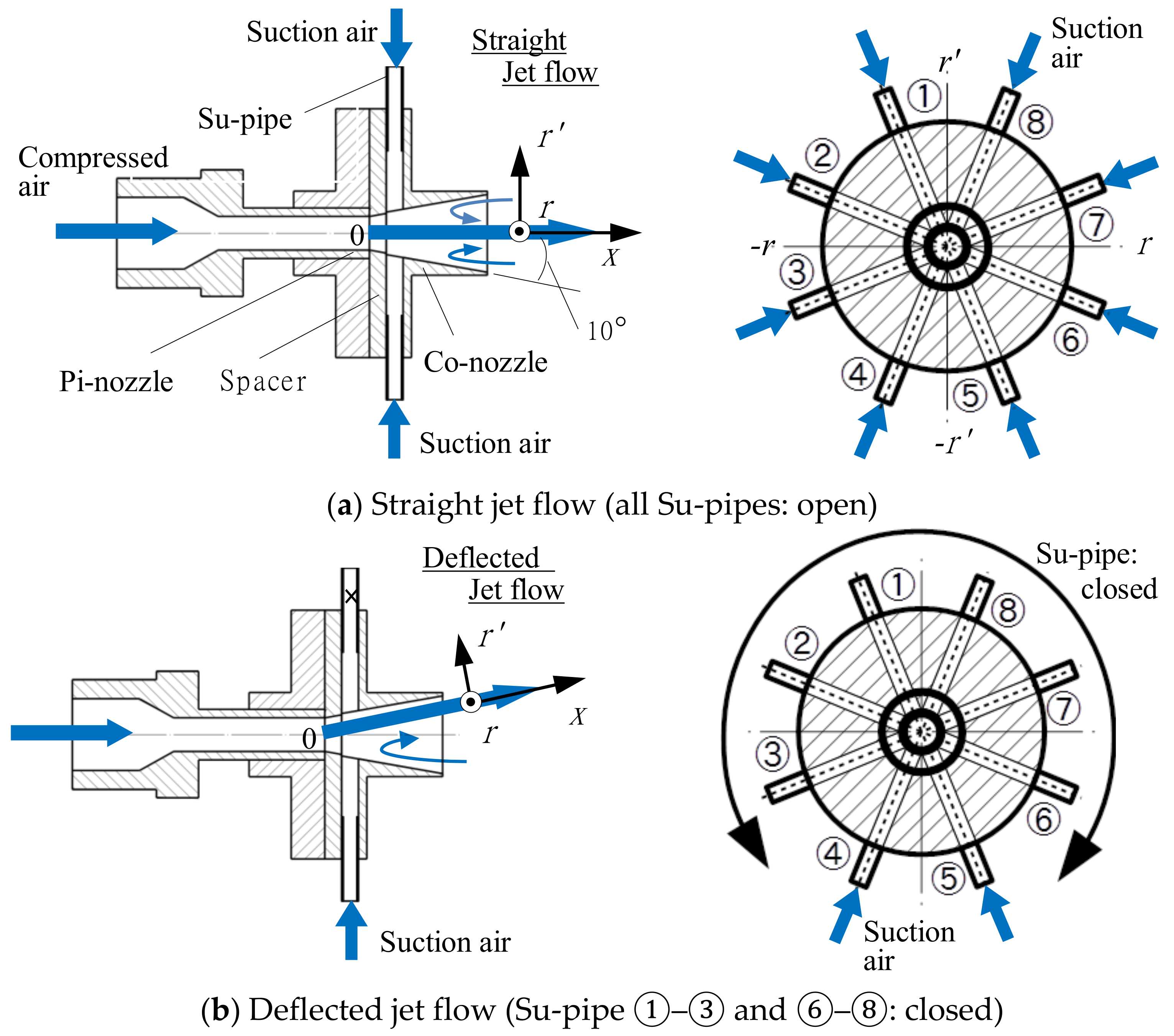
Figure 1. FC-nozzle (Fluidic thrust vector control of the Pi-jet by the FC-nozzle with 8 SU-pipes): When all Su-pipes are opened, the jet flows downstream along the nozzle axis, as shown in (a). When some Su-pipes are closed, the pressure between the outer edge of the jet and the wall of the Co-nozzle decreases and then the jet deflects to the closed side of Su-pipe by the Coanda effect as shown in (b).
Energies 15 08513 g001
Figure 2. Visualized flow pattern of the under-expanded supersonic jet issued from the Pi-nozzle produced by the Schlieren method, P0 = 0.380 MPa: The dotted lines indicate the approximate jet boundary with the position of r at u/uc = 0.1.
Energies 15 08513 g002
Figure 3. Visualized flow pattern of the jet issued from the FC-nozzle by Schlieren method, P0 = 0.38 MPa (Effect of suction flow): The deflection angle of the jet was measured using visualized flow pattern.
Energies 15 08513 g003
Figure 4. Deflection angle, β (P0 = 0.38, 0.48 MPa): The deflection angle has a maximum value of β = 10° at nc = 6.
Energies 15 08513 g004
Figure 6. Total pressure distribution, P/P0, in the cross section (0−, 6−closed jets, P0 = 0.380 MPa).
Energies 15 08513 g006
Figure 7. Static pressure distribution, Ps /P0, in the cross section at x/d0 = 5.4 (P0 = 0.38 MPa): The jet reattaches to the wall of the Co-nozzle at the +r’−axis side and entrains the surrounding fluid from the –r’-axis side of the negative pressure.
Energies 15 08513 g007
Figure 8. Cross sectional velocity distribution at x/d0 = 5.4 (P0 = 0.38 MPa): The velocity profile of the 6−closed nozzle is asymmetric because the jet deflects and reattaches to the side wall of the Co-nozzle.
Energies 15 08513 g008
Figure 9. Cross sectional velocity distribution at x/d0 = 4.2, 5.4, 8.3 (P0 = 0.38 MPa, Ps = Pa): The maximum velocity of the 0−closed case is approximately equal to that of the Pi-jet and is larger than that of the 8−closed case.
Energies 15 08513 g009
Figure 10. Thrust, F, of the supersonic jet from the FC-nozzle: The thrust of the 8-closed case is greater than that of the 0-closed case, and this seems to be due to the jet approaching proper expansion.
Energies 15 08513 g010
Figure 11. Deflection angle, β, of the 2-blow condition (P0 = 0.38 MPa, Qc = 10 [L/min]).
Energies 15 08513 g011
Figure 12. Deflection angle, β and blowing flow rate, Qc (P0 = 0.38 MPa): The deflection angle increases as Qc increases, and β also increases as the number of blowing nozzle nb decreases.
Energies 15 08513 g012
Figure 13. Deflection angle, β, and the number of Su-pipes blowing, nb (P0 = 0.38 MPa, Qc = 10 [L/min]): The deflection angle has a maximum value of β = 10° at n = 2.
Energies 15 08513 g013
Publisher’s Note: MDPI stays neutral with regard to jurisdictional claims in published maps and institutional affiliations.