Perspective

Progress of Coupled Heat Transfer Mechanisms of Regenerative Cooling System in a Scramjet

1
College of Aerospace Science and Engineering, National University of Defense Technology, Changsha 410073, China
2
Research Institute of Aerospace Technology, Central South University, Changsha 410012, China
*
Authors to whom correspondence should be addressed.
Energies 2023, 16(3), 1025; https://doi.org/10.3390/en16031025
Submission received: 5 December 2022 / Revised: 11 January 2023 / Accepted: 14 January 2023 / Published: 17 January 2023
(This article belongs to the Special Issue Advanced Propulsion System and Thermal Management Technology)

Abstract

:
The feasibility of regenerative cooling technology in scramjet engines has been verified, while the heat transfer behavior involved in the process needs further study. This paper expounds on the necessity of coupled heat-transfer analysis and summarizes its research progress. The results show that the effect of pyrolysis on heat transfer in the cooling channel depends on the heat flux and coking rate, and the coupling relationship between combustion and heat transfer is closely related to the fuel flow rate. Therefore, we confirm that regulating the cooling channel layout according to the real heat-flux distribution, suppressing coking, and accurately controlling the fuel flow rate can contribute to accomplishing the optimal collaborative design of cooling performance and combustion performance. Finally, a conjugate thermal analysis model can be used to evaluate the performance of various thermal protection systems.

1. Introduction

Hypersonic vehicles are a major development direction for the aeronautic and astronautic industries in the 21st century [1]. The constantly improved flight speed of hypersonic vehicles must be accompanied by a sharp increase in aerodynamic heating [2]. Scramjet is considered a promising power device for hypersonic vehicles because of its simple structure and high specific impulse [3]. Fast and efficient combustion is an inevitable prerequisite for the operation of scramjet engines [4]. However, the aerodynamic heating of the approaching airstream and the combustion heat release of fuel will produce enormous thermal loads, making scramjet engines endure severe thermal environment challenges during flight [5]. Therefore, scramjet engines must rely on effective thermal protection systems to ensure their operation stability. In particular, with the continuous increase in the flight Mach number, thermal protection technology is highly coupled with the working processes of the engine gas side and has become a technological bottleneck point limiting the improvements in engine performance.
Regenerative cooling is widely used in liquid rocket engines as a thermal protection technology, and its feasibility in scramjet engines has also been verified. For instance, the regenerative cooling scramjet engine X-51A successfully flew for 140 s [6]. The working process is that the pressurized fuel enters the cooling channel to remove the wall’s heat and then injects it into the combustion chamber to complete the combustion [7]. This method can not only cool the engine but also improves the performance of the scramjet [8]. The heat transfer modes involved in regenerative cooling mainly include three modules: convection and radiation heat transfer from the gas to combustion chamber inwall, heat conduction of the combustion chamber structure, and convection heat transfer from the hot wall to the coolant.
This paper summarizes the main characteristics of the regenerative cooling process of a scramjet engine, expounds on the necessity of coupled heat-transfer analysis, and introduces the research progress of the coupled heat-transfer technology. Furthermore, the main problems in the study of coupled heat transfer are discussed to provide a reference for the optimization design and practical application of the thermal protection system of the scramjet engine.

2. Necessity of Coupled Heat Transfer Analysis in Regenerative Cooling

The principal characteristics of the regenerative cooling process of a scramjet engine are as follows:
(1)
Fuel in the cooling channel operates in supercritical conditions, mainly to avoid heat transfer deterioration due to phase change, which may lead to the failure of the thermal protection system;
(2)
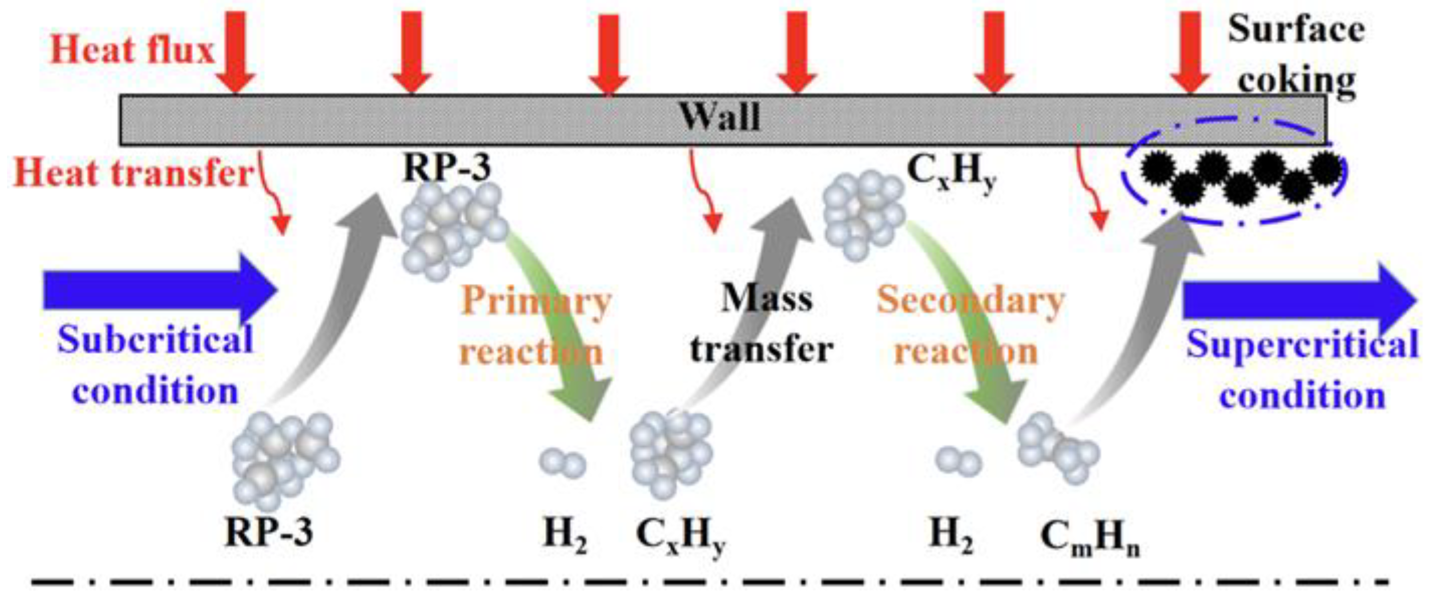
After exceeding the pyrolysis temperature, the endothermic hydrocarbon fuel will produce a pyrolysis reaction to form a mixture of small molecule gases, providing an additional chemical heat-sink;
(3)
Fuel composition and physical properties change dramatically during cooling due to the combined action of endothermic and cracking reactions;
(4)
Coking may occur during the endothermic pyrolysis of fuel, and the formation of coking deposits will lead to heat transfer deterioration and even channel blockage;
(5)
The change in fuel composition will also affect its combustion performance; in addition, the thermal environment of the combustor wall is determined by the combustion performance and cooling efficiency.
Aiming at the thermal environment and the above characteristics of a scramjet engine, scholars have carried out extensive research on aerodynamic heating, supersonic combustion, and supercritical flow heat transfer. However, few studies that have jointly considered these aspects. In terms of the heat transfer characteristics of supercritical fluid in a cooling channel, most of the existing studies have used fixed heat flux boundary conditions. However, the research by Zhao et al. [9] showed that the effects of constant and variable heat flux on the pyrolysis process were different; they considered it necessary to study the coupling mechanism of endothermic hydrocarbon fuel pyrolysis and heat transfer under non-uniform heat flux. In the study of Han et al. [10], the influence of the coupling effect on temperature results was more than 100 K, strongly supporting Zhao and colleagues’ conclusion.
In summary, the coupled heat transfer mechanism in the combustor is crucial for scramjet engines’ optimal collaborative design.

3. Research Progress of Regenerative Cooling Coupled Heat Transfer in Scramjet

According to the above analysis, the following discussion will include: the pyrolysis heat transfer coupling in the cooling channel, the combustion and heat transfer coupling in the combustion chamber, and the conjugate thermal analysis considering aerodynamic heating in the regenerative cooling of scramjet engines.

3.1. Pyrolysis Heat Transfer Coupling in the Cooling Channel

Figure 1 [11] shows that the fuel in the cooling channel will undergo a chemical reaction after the temperature exceeds the critical temperature, which will further affect the flow and heat transfer process. For this coupling relationship and interaction mechanism, Feng et al. [12,13] found that a chemical reaction boundary exists during the flow development in a tube beside the velocity and temperature boundary layer; in addition, they also established a one-dimensional framework to amplify the coupling relationship between flow and pyrolysis reaction and defined the characteristic time to quantitatively describe its coupling scale.
From the perspective of flow characteristics, Jiang et al. [14] numerically analyzed the effect of supercritical n-decane pyrolysis on heat transfer performances. The results showed that the small molecular substances produced by pyrolysis reduced the overall density, the diffusion capacity of fuel components was enhanced, and the inhomogeneity of flow distribution was reduced. Lei et al. [15] analyzed the evolution process of coupled heat transfer in pyrolysis from the perspectives of boundary layer development, turbulent shear stress, and thermophysical properties. The results showed that the heat transfer coefficient was positively correlated with the mass flow rate, negatively correlated with the equivalent diameter, and nonlinearly correlated with the heat flux density. Meanwhile, the effect of heat flux was related to the development of the thermal boundary layer and the change of thermophysical properties caused by pyrolysis. Tian et al. [16] considered that the pyrolysis reaction of RP-3 fuels could increase the velocity at the outlet of the channel by three times. Moreover, Li et al. [17] quantitatively calculated the effect of the cooling channel aspect ratio on heat transfer capacity. The results showed that the increase in the aspect ratio improved the heat transfer performance of the main flow region. The heat transfer coefficient at the aspect ratio of 5 was five times higher than that at the aspect ratio of 3, and the wall temperature at the corner was increased by 4K.
Pyrolysis usually occurs first at high-temperature regions near the wall. Li et al. [18] studied to what purpose this occurred and found that the effect of pyrolysis on heat transfer was nonlinearly related to the variety of heat flux, which was related to the secondary products produced by pyrolysis and the thermal boundary layer effect. The secondary product influenced the fuel composition, causing an increase in viscosity, affecting the thermal diffusivity, and thus reducing the Nusselt number. Meanwhile, the pyrolysis near the wall caused dramatic changes in the radial distribution of the fluid, changed the thermal properties in the boundary layer, and led to the deterioration of heat transfer. Tian et al. [11] also obtained the same conclusion and elaborated from the perspective of hydrocarbon fuel chemical heat sink, flow transition, and ultra-high wall temperature. They reported that the pyrolysis reaction provided a chemical heat sink and accelerated the flow rate, thereby reducing the fuel heating rate and wall temperature. At the same time, the mass fraction of small molecule products increased along with the pyrolysis reaction, and the risk of surface coking and carbon deposition also increased. In addition, Gong et al. [19] numerically studied the effect of the secondary reaction on the heat transfer in reacting flow and reported that the heat transfer efficiency reaches a maximum value with increased hydrocarbon fuel conversion.
Jiao et al. [20,21] experimentally studied the pyrolysis heat-transfer coupling characteristics of RP-3 flowing in a vertical upward tube at supercritical pressures in the context of the buoyancy effect. The results showed that under the condition of high heat flux, the buoyancy effect will lead to heat transfer deterioration which cannot be restored by increased pressure. Pyrolysis promotes the heat transfer performance of fuel by doubling the average thermal conductivity in the pyrolysis zone. Next, they focused on microscopic heat-transfer behavior in the heat transfer deterioration and the cracked region by numerical simulation. They considered that pyrolysis affected heat transfer by two mechanisms: furnish heat absorption or deliver capacity through the endothermic (exothermic) chemical reactions and modify fuel composition and physical properties. The two factors interact and work together to produce different results in different regions. In addition, Li et al. [22] studied the coupling effect of pyrolysis and flow heat transfer from the perspectives of wall temperature distribution, thermal acceleration, n-decane mass fraction, streamline characteristics, and vortex structure. The results showed that pyrolysis reduced the shear stress and turbulent kinetic energy, reducing the velocity difference between the viscous sublayer and the buffer layer, and increasing the near-wall temperature. From another perspective, the high cracking in the near-wall region significantly reduces the density of fuel components, increases the velocity in the boundary layer, and further reduces the wall temperature. This means that thermal acceleration is beneficial to enhance heat transfer. In addition, the vortex structure generated by pyrolysis also increases heat transfer.
It is worth noting that coking is often accompanied by pyrolysis, so it is necessary to further consider coking in pyrolysis-coupled heat transfer. An experiment was conducted by Wang et al. [23] to study the impact of the S-bend tube and mass flow rate on the thermal cracking and coke deposition behavior of supercritical aviation kerosene RP-3. When the outlet temperature of RP-3 was 600–700 °C, the conversion rate of the S-bend tube was 9.3% higher than that of the straight tube, and the gas yield was also slightly increased. This can be due to the secondary flow and Dean vortex formed by the bending structure affecting the flow field structure. The dual effects of high temperature and low speed promote thermal cracking in the core area of the S-bend tube. While the secondary flow enhances the fuel mixing effect, it also increases the local resistance, making the coke precursor easier to deposit near the wall and causing additional coking. On the other hand, the increase in mass flow affects the fuel’s temperature, velocity, and turbulent kinetic energy, thereby reducing the cracking conversion rate and coke deposition rate. Furthermore, Zhang et al. [24] proposed a framework for 2D dynamic coking research by simultaneously coupling the detailed pyrolysis model of n-decane that involved secondary reactions with the MC-II coking model. Coking kinetics and their effect on flow and heat transfer characteristics have been studied in depth. The results showed that the framework established by dynamic mesh technology can better simulate the coking process and reflect the uneven distribution of deposited coke. Maximum conversion of n-decane obtained simultaneously was independent of the coking process. Finally, three penalties for coking are summarized. The increase in the maximum temperature increases the risk of solid structure breaking, the increase in thermal resistance decreases cooling performance, and the decrease in flow cross-sectional area increases pressure drop.

3.2. Combustion and Heat Transfer Coupling in the Combustion Chamber

Due to the dual role of fuel in regenerative cooling technology, there is a highly coupled relationship between fuel pyrolysis and combustion, which determines the heat flux, wall temperature, and structural stress response of the combustion chamber wall, and is critical to the design of thermal protection systems. To study this coupling relationship, establishing a one-dimensional mathematical model with fast calculation is a relatively easy solution. A typical one-dimensional model contains three modules of the heat transfer process, as shown in Figure 2. Zhang et al. [25] evaluated the performance of active thermal protection systems at different Mach numbers and equivalence ratios by the above model. In addition, the performance of the active thermal protection system and the active–passive combined thermal protection system is compared and analyzed. The results show that the combined thermal protection system can effectively reduce the wall temperature of the combustion chamber due to the role of the passive layer insulation material.
However, experimental studies can more realistically reflect this coupling relationship. Taddeo et al. [26] designed a regeneratively cooled combustor to study pyrolysis-combustion coupling and fuel-coking activity. Under the experimental conditions of ethylene as fuel and air as oxidant, the effects of fuel mass flow and equivalence ratio as two command parameters on the thermal environment of the combustion chamber were determined. The characterization parameters included the heat flux between the burned gas and the inner wall of the combustion chamber, the heat flux absorbed by the fuel in the cooling channel, and the heat transfer efficiency of the combustion chamber. The experimental results showed that when the first command parameters increased by 16–20%, the heat flux density of the corresponding gas side increased by 20% and 28%, which was determined by the equivalence ratio and pressure. The cooling side’s physical and chemical heat fluxes were positively correlated with both command parameters. Similarly, the heat transfer efficiency of the combustor also increased with the increase in the fuel mass flow rate and changed nonlinearly with the increasing equivalence ratio, which means that there exists a maximum value. In addition, the sensitivity analysis of two characteristic heat fluxes to command parameters was performed. In the study of combustion conditions, it is found that when the equivalence ratio is greater than 1, radiative energy transfer accounts for more than thermal convection. The opposite is true when the equivalence ratio is equal to 1. Finally, the coking activity of ethylene was studied by monitoring the fuel pressure drop in the cooling channel.
In addition, the thermo-fluid-solid coupling is noteworthy. Gopinath et al. [27] numerically studied the three-dimension semi-couple transient fluid–thermal–structural response of the metallic sandwich panel with a corrugated core during hypersonic accelerated cruise-flight. The semi-coupled fluid–thermo–structural analysis methodology numerical framework is shown in Figure 3. The thermo-structural loads are estimated by adopting a high-speed gas-dynamic flow model bonded with Eckert’s reference temperature. Taking the flight condition of Mach number 7 as an example, the coolant’s flow and heat transfer characteristics are discussed, and the results of the directional displacement response of sandwich plates with and without cooling are compared and analyzed. The results show that the active cooling system not only improves the thermal protection capability by 70% but also reduces the bending deformation of the panel thermal structure response by 90%. In conclusion, the defect in the coupling of the thermal load and the cooling side is not considered in the method developed in this paper. Therefore, it is necessary to further develop the research method of flow–thermal–structural bidirectional coupling. To solve the problem of limited coolant for scramjet engines, Zhang et al. [28] proposed a topology optimization design method for the fluid-structure correlation of regenerative cooling channels to improve the overall heat transfer efficiency. The topology optimization structure of the cooling channel adopts the variable density method and takes heat transfer efficiency as the objective function. Under different heat flux distributions, the flow and heat transfer processes in the structure are quantitatively analyzed. The results show that the topological channel’s average wall temperature and pressure drop are reduced by 5.8% and 20.6%, respectively, and the uniformity of the hot wall temperature is increased twice. The reason is that the microchannel perpendicular to the mainstream direction can distribute the inlet fuel to the adiabatic wall surface, thereby improving flow uniformity. However, the backflow phenomenon at the inlet and the “capillary” zone near the outlet will weaken the local heat transfer, resulting in a local high-temperature zone that needs further study.

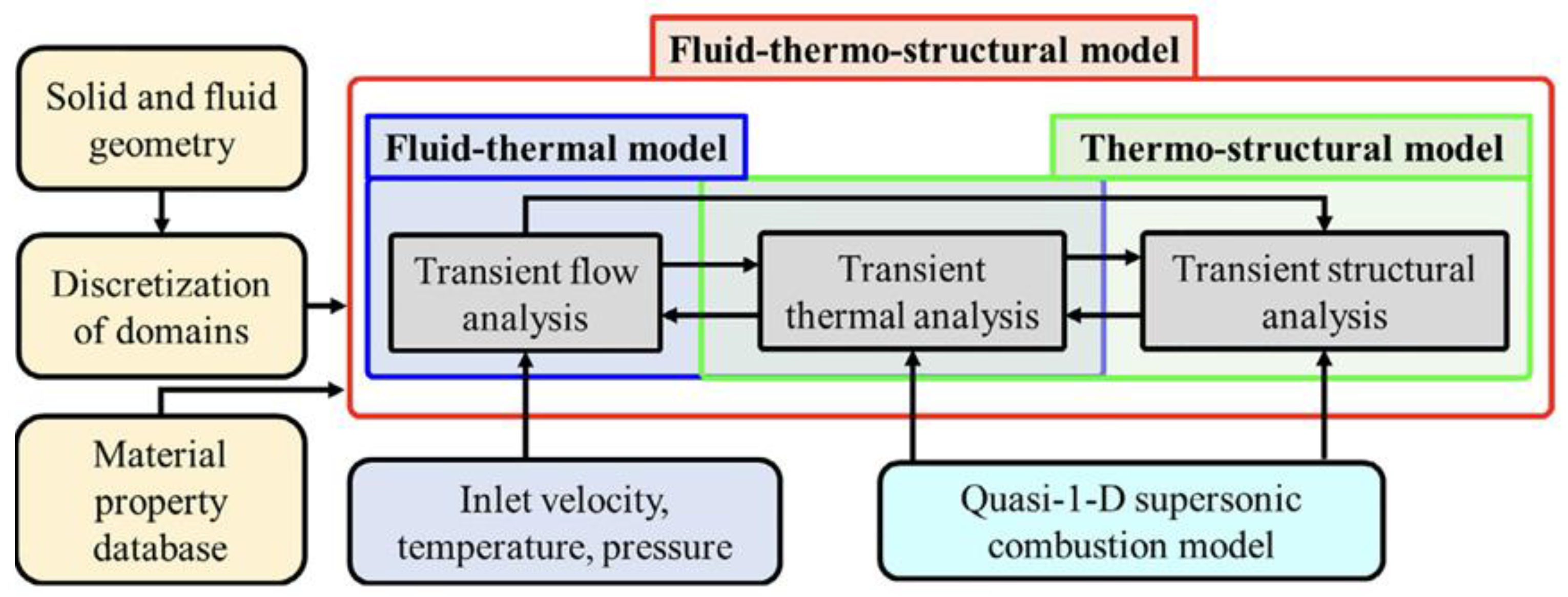
3.3. Conjugate Thermal Analysis Considering Aerodynamic Heating

To evaluate the thermal state of the components of a scramjet engine, it is necessary to comprehensively consider aerodynamic heating, combustion heat release, and cooling heat transfer, which require conjugate thermal analysis. Han et al. [10] innovatively developed a method for conjugate thermal analysis of regeneratively cooled scramjet engines. The scheme uses the principle of energy conservation to iteratively calculate the aerodynamic heating of the aircraft’s inner and outer surface, the internal combustion heat release and structural thermal analysis, and the convective heat transfer of the coolant on the two interfaces. Specifically, the external flow field of the aircraft was calculated under adiabatic and isothermal boundary conditions. The aerodynamic heating of the scramjet surface was calculated by the direct correction method and used as the input condition to solve the structural thermal equation. Moreover, the additional heat load caused by the combustion phenomenon was reflected by increasing the adiabatic surface temperature in the combustion chamber. In addition, based on the assumption that the internal space of the aircraft is full of fuel and saturated steam, the average temperature of its volume was estimated. Concomitantly, the flow rate of n-dodecane in the cooling channel was calculated. The schematic diagram of the thermal analysis scheme and the flowchart of conjugate heat transfer is shown in Figure 4 and Figure 5, respectively. Thus, the temperature fields of the outer surface of the scramjet, the inner surface near the combustion chamber, the internal space, and the cooling channel were obtained. Comparing the numerical results for Mach 6 at an altitude of 22.342 km, it was found that the coolant outlet temperature increased by up to 107 K after considering the aerodynamic heating absorbed by the internal space from the thermal structure. In some exceptional cases, however, cooling channels further heat the internal space in a complex way.
Furthermore, based on the developed numerical calculation method, the appropriate material can be selected subsequently according to the temperature of each component, which can also be used as the basis for the relevant design parameters of the cooling channel, such as the mass flow rate of the coolant, the inlet temperature and pressure, and the geometric parameters of the channel. In addition, an appropriate arrangement of payloads consisting of the internal system from a thermal point of view can be designed based on the internal space temperature of the aircraft. In summary, the advantage of conjugate thermal analysis is the ability to consider the coupling of all factors, which can be an important reference for the optimal design of the thermal protection system of the scramjet engine.

4. Conclusions

This paper illustrates the necessity of research on coupled heat transfer of regenerative cooling technology for scramjet engines and summarizes its research progress. The following conclusions can be drawn:
(1)
Pyrolysis in the cooling channel is not always conducive to heat transfer but is related to the heat flux and coking rate. Therefore, it is worthy of further study to regulate the cooling channel layout according to the actual heat flow distribution and suppress coking;
(2)
The coupling relationship between combustion and heat transfer in the combustion chamber needs more in-depth research to achieve the optimal collaborative design of cooling performance and thrust performance. On the other hand, apart from calculating the one-way thermal structure response, the two-way coupling of the structure after thermal deformation and the flow field also needs to be explored;
(3)
Further validating and improving the accuracy of the conjugate thermal analysis model and using it to evaluate the performance of various thermal protection systems can significantly save test and time costs.

Author Contributions

Conceptualization, C.L.; writing—original draft preparation, N.H.; writing—review and editing, Y.P., C.L. and J.L. All authors have read and agreed to the published version of the manuscript.

Funding

This research received no external funding.

Data Availability Statement

Not applicable.

Conflicts of Interest

The authors declare no conflict of interest.

References

  1. Fry, R.S. A century of ramjet propulsion technology evolution. J. Propul. Power 2004, 20, 27–58. [Google Scholar] [CrossRef]
  2. Mosavat, M.; Moradi, R.; Barzegar, M. The influence of coolant jet direction on heat reduction on the nose cone with Aerodome at supersonic flow. J. Acta Astronaut. 2018, 6, 26. [Google Scholar]
  3. Curran, E.T. Scramjet engines: The first forty years. J. Propul. Power 2001, 17, 1138–1148. [Google Scholar] [CrossRef]
  4. Barzegar, M.; Amini, Y.; Fallah, K. The flow feature of transverse hydrogen jet in presence of micro air jets in supersonic flow. J. Adv. Space Res. 2016, 11, 40. [Google Scholar]
  5. Song, K.D.; Choi, S.H.; Scotti, S.J. Transpiration cooling experiment for scramjet engine combustion chamber by high heat fluxes. J. Propul. Power 2006, 22, 96–102. [Google Scholar] [CrossRef]
  6. Hank, J.; Murphy, A.; Mutzman, R. The X-51A scramjet engine flight demonstration program. In Proceedings of the AIAA International Space Planes & Hypersonic Systems & Technologies Conference, Dayton, OH, USA, 28 April–1 May 2008. [Google Scholar]
  7. Gascoin, N.; Abraham, G.; Gillard, P. Thermal and hydraulic effects of coke deposit in the hydrocarbon pyrolysis process. J. Thermophys. Heat Transf. 2012, 26, 57–65. [Google Scholar] [CrossRef]
  8. Miao, H.Y.; Wang, Z.W.; Niu, Y.B. Performance Analysis of Cooling System Based on Improved Supercritical CO2 Brayton Cycle for Scramjet. J. Appl. Therm. Eng. 2019, 19, 114774. [Google Scholar] [CrossRef]
  9. Zhao, Y.; Wang, Y.; Liang, C. Heat transfer analysis of n-decane with variable heat flux distributions in a mini-channel. Appl. Therm. Eng. 2018, 144, 695–701. [Google Scholar] [CrossRef]
  10. Han, D.B.; Kim, J.S.; Kim, K.H. Conjugate thermal analysis of X-51A-like aircraft with regenerative cooling channels. Aerosp. Sci. Technol. 2022, 126, 107614. [Google Scholar] [CrossRef]
  11. Tian, K.; Yang, P.; Tang, Z.C. Effect of pyrolytic reaction of supercritical aviation kerosene RP-3 on heat and mass transfer in the near-wall region. Appl. Therm. Eng. 2021, 197, 117401. [Google Scholar] [CrossRef]
  12. Feng, T.; Qin, J.; Zhang, S.L. Modeling and analysis of heat and mass transfers of a supercritical hydrocarbon fuel with pyrolysis in mini-channel. J. Heat Transfer 2015, 91, 520–531. [Google Scholar] [CrossRef]
  13. Feng, T.; Zhang, S.L.; Cao, J. Coupling relationship analysis between flow and pyrolysis reaction of endothermic hydrocarbon fuel given characteristic time correlation in mini-channel. Appl. Therm. Eng. 2016, 16, 30486. [Google Scholar]
  14. Jiang, Y.G.; Qin, J.; Chetehouna, K. Effect of geometry parameters on the hydrocarbon fuel flow rate distribution in pyrolysis zone of SCRamjet cooling channels. J. Heat Transf. 2019, 141, 1114–1130. [Google Scholar] [CrossRef]
  15. Lei, Z.L.; He, K.; Huang, Q. Numerical study on supercritical heat transfer of n-decane during pyrolysis in rectangular tubes. Appl. Therm. Eng. 2020, 170, 115002. [Google Scholar] [CrossRef]
  16. Tian, K.; Tang, Z.C.; Wang, J. Simplified pyrolytic model of RP-3 fuel at high conversion rates and the effects of primary reaction on the regenerative cooling process. Aerosp. Sci. Technol. 2022, 129, 107853. [Google Scholar] [CrossRef]
  17. Li, Z.Z.; Li, Y.; Zhang, X.W. Coupling of pyrolysis and heat transfer of supercritical hydrocarbon fuel in rectangular minichannels. Chem. Eng. Sci. 2022, 247, 116924. [Google Scholar] [CrossRef]
  18. Li, Z.Z.; Liu, G.Z.; Zhang, R.L. Heat transfer to supercritical hydrocarbon fuel in horizontal tube: Effects of near-wall pyrolysis at high heat flux. Chem. Eng. Sci. 2021, 229, 115994. [Google Scholar] [CrossRef]
  19. Gong, K.Y.; Cao, Y.; Feng, Y. Influence of secondary reactions on heat transfer process during pyrolysis of hydrocarbon fuel under supercritical conditions. Appl. Therm. Eng. 2019, 159, 113912. [Google Scholar] [CrossRef]
  20. Jiao, S.; Li, S.F.; Pu, H. Experimental investigation on thermal cracking and convective heat transfer characteristics of aviation kerosene RP-3 in a vertical tube under supercritical pressures. J. Therm. Sci. 2019, 146, 106092. [Google Scholar] [CrossRef]
  21. Jiao, S.; Li, S.F.; Pu, H. Investigation of pyrolysis effect on convective heat transfer characteristics of supercritical aviation kerosene. Acta Astronaut. 2020, 171, 55–68. [Google Scholar] [CrossRef]
  22. Li, Y.; Wang, J.B.; Xie, G.N. Effect of thermal pyrolysis on heat transfer and upward flow characteristics in a rectangular channel using endothermic hydrocarbon fuel. Chem. Eng. Sci. 2021, 244, 116806. [Google Scholar] [CrossRef]
  23. Wang, R.T.; Zhao, J.J.; Bao, Z.W. Thermal cracking and coke deposition characteristics of aviation kerosene RP-3 in an S-bend tube. Fuel 2022, 313, 122673. [Google Scholar] [CrossRef]
  24. Zhang, C.; Gao, H.; Zhao, J.J. Dynamic coking simulation of supercritical n-decane in circular tubes. Fuel 2023, 331, 125859. [Google Scholar] [CrossRef]
  25. Zhang, C.; Qin, J.; Yang, Q.C. Design and heat transfer characteristics analysis of combined active and passive thermal protection system for hydrogen-fueled scramjet. Int. J. Hydrogen Energy 2015, 40, 675–682. [Google Scholar] [CrossRef]
  26. Taddeo, L.; Gascoin, N.; Chetehouna, K. Experimental study of pyrolysis-combustion coupling in a regeneratively cooled combustor: Heat transfer and coke formation. Fuel 2019, 239, 1091–1101. [Google Scholar] [CrossRef]
  27. Gopinath, N.K.; Govindarajan, K.V.; Mahapatra, D.R. Fluid-thermo-structural response of actively cooled scramjet combustor in hypersonic accelerating-cruise flight. J. Heat Transf. 2022, 194, 123060. [Google Scholar] [CrossRef]
  28. Zhang, T.; Jing, T.T.; Qin, J. Topology optimization of the regenerative cooling channel in the non-uniform thermal environment of hypersonic engineopology optimization of regenerative cooli thermal environment of the hypersonic engine. Appl. Therm. Eng. 2023, 219, 119384. [Google Scholar] [CrossRef]
Figure 1. The schematic of heat and mass transfer in the cooling channel [11].
Energies 16 01025 g001
Figure 2. Schematic diagram of one-dimensional coupled heat transfer model of hydrogen fuel scramjet [25].
Energies 16 01025 g002
Figure 3. Numerical framework of the semi-coupled fluid–thermo–structural analysis methodology [27].
Energies 16 01025 g003
Figure 4. Regimes considered for thermal analysis of X-51A-like aircraft [10]. (The purple marking region in the figure represents the internal flow region of the engine including the cooling channel).
Energies 16 01025 g004
Figure 5. Flowchart of conjugate heat transfer [10].
Energies 16 01025 g005
Disclaimer/Publisher’s Note: The statements, opinions and data contained in all publications are solely those of the individual author(s) and contributor(s) and not of MDPI and/or the editor(s). MDPI and/or the editor(s) disclaim responsibility for any injury to people or property resulting from any ideas, methods, instructions or products referred to in the content.

