Abstract
Two-phase flow in non-circular cross-section flow channels such as micro-heat sinks and micro-channel heat exchangers has received extensive attention due to its heat-enhancing properties. In this paper, under the boundary of constant heat flux, an experimental investigation of the heat transfer properties of gas–liquid two-phase flow in horizontal channels with cross-sections of 4 × 4 mm and 8 × 3 mm is carried out using air and water as working fluids. The effects of different inlet gas and liquid inlet Reynolds numbers on the wall temperature and Nusselt number are discussed. The results show that the effects of the liquid Reynolds number and the gas phase Reynolds number on the heat transfer coefficient of the square tube and the rectangular tube are different. Under the same gas–liquid Reynolds number, the Nusselt number of the gas–liquid two-phase flow in the square-section tube can be increased by 3.2 times compared with that in the single-phase flow, while the Nusselt number of the gas–liquid two-phase flow in the rectangular tubes can be increased by 1.87 times. The results of this paper provide a reference for the design of microchannel heat exchangers and the establishment of mathematical models for Taylor flow heat transfer in rectangular and square tubes.
1. Introduction
Gas–liquid two-phase flow widely exists in petrochemical and other equipment involving a large number of heat and mass transfer and chemical reactions. With the rapid development of micro-fabrication technology in recent years, there are a large number of non-circular cross-section channels, such as square and rectangular, in actual micro-chemical equipment [1] and micro-electronic radiators [2], compact heat exchangers [3] and other equipment. The gas–liquid two-phase heat transfer in the channel has become a research hotspot outside the circular cross-section channel.
From the published literature, the research mainly focuses on Taylor flow heat transfer in two-dimensional or circular channels. Scammell et al. [4] investigated the flow and heat transfer of a single Taylor bubble in a vertical 6 mm tube and calculated the local heat transfer coefficient of the bubble. They reported that the decisive factor to enhance heat transfer is turbulent mixing, which is caused by vortex shedding. At the same time, it is found that with the increase in the liquid Reynolds number, the effect of a vortex on heat transfer decreases. Zhang et al. [5] carried out numerical simulations of Taylor flow in vertical circular tubes with diameters of 0.5, 1 and 2 mm under constant heat flux. It was found that with the increases in pipe diameter, Reynolds number and reduction in gas void fraction, the average Nusselt number rises. The Nu is approximately 1.2 to 3 times that of the single phase. Gas–liquid two-phase flow in a two-dimensional microchannel was simulated using a fixed computational domain method by Wang et al. [6]. They found that the addition of the gas phase increased the pressure drop, and, at a lower mixing velocity, the temperature field became asymmetric. When the gas void fraction increases, the heat transfer decreases. Compared with the single-phase flow, the heat transfer rate of the liquid–liquid two-phase flow in the microchannel is significantly increased, and the Nusselt number in the microchannel can be increased by 600% [7]. Kumari et al. [8] studied the shape and heat transfer characteristics of the gas–liquid two-phase flow in a 1 mm circular tube. They proposed the bubble dimensionless equivalent diameter Reqv and found that when Reqv is less than 1, as the Reynolds number increases and the Nusselt number increases, the bubble head becomes sharp and the tail becomes flat, and when Reqv is greater than 1, the Nusselt number and Reynolds number are independent.
The research on the gas–liquid two-phase flow in the square channel is divided into two aspects: numerical simulation and experimental research. In experimental research, Shin et al. [9] used two mixers to perform experimental research on the two-phase flow of gas and liquid in a rectangular duct with a hydraulic diameter of 1.33 mm. Seven flow patterns were proposed for the classification of the observed gas–liquid two-phase flows. They evaluated two-phase flow pattern maps in microchannels and found that the thermophysical properties of the working fluid, the configuration of gas–liquid mixers, the hydraulic diameter of the channel and the shape of the cross-sectional area all have an impact on flow patterns. In a square channel, a spatially varying asymmetric flow field is formed when the liquid flows through the liquid film between the bubble and the wall. Azadi et al. [10] utilized PIV to measure the liquid flow velocity field in a 3 mm-wide square channel and simulated the liquid film near the wall. The experimentally measured velocity was consistent with the numerical simulation results. The flow field in the square channel encounters a backflow phenomenon. The local liquid flows in the opposite direction, and the backflow area decreases as both the fluid and bubble velocities rise. Majumder et al. [11] heated the bottom of a square channel with a side length of 3.3 mm and kept the other three sides insulated to study the effect of a single bubble and multiple bubbles on heat transfer in the channel. By changing the air mass flow rate at the inlet, the Nusselt number of the two-phase flow was found to be 1.2–1.6 times that of the fully developed single-phase liquid flow. To further explore the heat transfer characteristics of the square channel, Mehta et al. [12] fabricated a square channel with a cross-section of 5 × 5 mm on stainless steel and applied a constant heat flux density to the three sides of the channel. Using an infrared camera, they measured the local Nusselt number of the two-phase flow of water and air in the aforementioned channel and found that the Taylor bubble flow increases the Nusselt number by 1.2–2 times compared to a fully developed single-phase flow. Abdollahi et al. [13,14] conducted experiments and numerical simulations of liquid–liquid two-phase flow in a square channel with hydraulic diameters of 1 mm and 2 mm. It was found that the pressure drop of droplets increased with increasing Ca. When the mixture’s superficial velocity is constant, changing the size of the droplet volume, the velocity and shape of the droplet do not change, and the velocity of the droplet is about 110% of the mixture’s superficial velocity. Compared with the single-phase flow, the Nusselt number of the liquid–liquid Taylor flow can be increased by 700%. The experimental correlations between Nusselt number and liquid film thickness and pressure drop for predicting liquid–liquid two-phase flow were established by them.
The research progress on the numerical simulation of square and rectangular channels is as follows: Bayareh et al. [15] used air and Al2O3-water nanofluid as a working fluid to study the thermal characteristics of two-phase flow in rectangular microchannels with three different inlet structures, and the vortices and fluctuations in the liquid film around the bubble were demonstrated. They pointed out that the liquid film had a great influence on the slug heat transfer, and the vortices made the gas void fraction in the channel lower than the homogeneous void fraction. The heat transfer coefficient using nanofluids is 110% of that of water. Zhang et al. [16] performed numerical simulations of square and rectangular tubes with water and ethylene glycol as the liquid phase and nitrogen as the gas phase. When the capillary number changes from small to large, the bubble shape of the square tube and rectangular tube changes from asymmetry to symmetric. The recirculation intensity decreases as the number of capillaries grows, the two-phase Nusselt number decreases with increasing gas holdup and a Nusselt number correlation for predicting square and rectangular channels is established. Che et al. [17] conducted numerical simulations of droplet heat transfer in rectangular cross-section microchannels and found that in square microchannels, the liquid flows in the axial direction at the corners, while the heat transfer is in the radial direction. Wall heat flux is transferred to the central fluid only by conduction. In contrast, the recirculation vortex allows the droplets in other regions to exchange heat with the fluid in the center. Thus, the thermal resistance of the liquid film regions at the corners is greater. For high Peclet numbers, the Nusselt number is larger. Talimi et al. [18] carried out a numerical study of Taylor flow in a square microchannel at constant wall temperature. They used an integral method to convert the local heat flux of the moving liquid slug into the average heat flux of the channel and revealed that Taylor flow is significantly influenced by the contact angle. The Reynolds number changes the flow pattern and the length of the slug, which significantly affects heat transfer, and the correlation of the heat transfer coefficient under different slug length and Reynolds number is proposed. Ferrari et al. [19] utilized numerical simulation to investigate the phase change heat characteristics of refrigerants in circular and square cross-section channels and found that under the same Reynolds number and capillary number, compared to the circular tube, the bubble velocity was higher in the square channel. The liquid film thickness at the walls is significantly less than that at the corners as the capillary number falls. The difference in the curvature of the bubble interface at the corners and the walls causes lateral flow to thicken the liquid film at the corners and thin the liquid film at the walls.
The cross-sectional shape in a microchannel has a significant effect on fluid flow and heat transfer. Most authors only study and compare channels with the same cross-sectional shape and different hydraulic diameters or different working fluids in the same cross-sectional channel, and there is a lack of experimental studies on gas–liquid two-phase flow in square and rectangular channels in the published literature [20]. In order to grasp and predict the heat transfer characteristics of gas–liquid two-phase in square and rectangular channels, it is necessary to conduct experimental research on them. In this paper, air and water are used as working fluids, and the heat transfer experiments of channels with cross-sections of 4 × 4 mm and 8 × 3 mm are carried out. The influence of the Reynolds number of the gas and liquid phase and the length of liquid slug on the heat transfer characteristics of square and rectangular channels is discussed.
2. Experimental System and Method
2.1. Experimental System
As depicted in Figure 1, the experimental system mainly includes four parts: gas phase supply unit, liquid phase circulation unit, small channel of experimental section and experimental data collection unit.
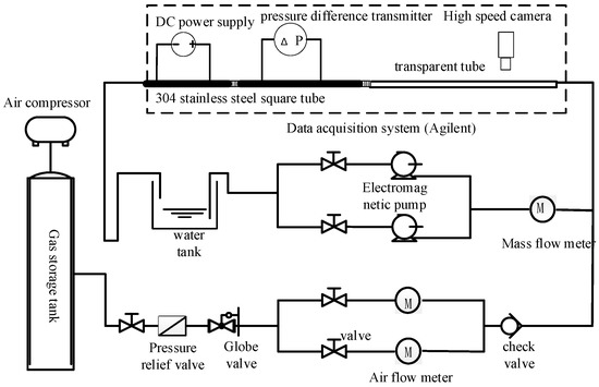
Figure 1.
Experimental system diagram.
The air compressor, gas storage tank and the air flow meter make up the majority of the gas phase supply system. First of all, the air compressor compresses and stores the air in the 100 L storage cylinder of the air compressor. The air compressor has a displacement of 420 L/min and a power of 4.5 KW. During the experiment, in order to guarantee the flow pattern’s stability and minimize the experimental error brought about by the fluctuation in gas pressure to the subsequent pressure measurement, a vertical gas storage tank with a volume of 300 L was connected to the air compressor, and the rated pressure of the gas storage tank was 0.7 MPa. For precise control and real-time monitoring of gas flow, the gas in the tank flows through pressure relief valves and globe valves into the gas mass flowmeter. In order to meet the demand of experimental gas phase flow rate, two kinds of gas mass flowmeters with ranges of 0–2 L/min (model D07-19B) and 0–50 L/min (model D07-9E) are used. The liquid phase circulation system is mainly composed of a micro gear pump and Coriolis flowmeter. The micro gear pump has the characteristics of low noise, no pulsation and stable operation, which can effectively minimize the experimental error brought on by the pulse pressure drop signal. Therefore, the micro gear pump with range of 20–1000 mL/min (MG204XK) and 100–2500 mL/min (MG209XK) is used in the experiment. The CX-CMFI Coriolis flowmeter is used to monitor the mass flow rate of liquid in real time. The measurement range is 0–700 kg/h, and the accuracy is ± 0.2%. The experimental section is mainly divided into visual flow pattern observation channel and temperature measurement part. The visualization tube part is made of 3D printed transparent photosensitive resin, and the pressure measurement tube and heat transfer parts are made of 304 stainless steel, which are connected through rubber hoses. As shown in Figure 2, the experimental section is mainly composed of a flow pattern observation unit and temperature measurement unit. The experimental small channel has two cross-section shapes. The cross-section size of the small square stainless steel channel is 4 mm × 4 mm (wall thickness 0.5 mm), and the cross-section of the rectangular stainless steel tube is 8 mm × 3 mm (wall thickness 0.5 mm). The cross-section size of the small experimental channel was measured with vernier calipers, and its minimum accuracy was 0.05 mm.
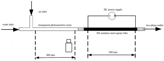
Figure 2.
Schematic diagram of the experimental section.
Heating system and temperature measuring unit: The experimental section is heated by tightly wound thermal resistance wire. The wall temperature of the tube is measured by thermocouples. To reduce the disturbance to the flow pattern in the tube, thermal resistance with a diameter of 0.3 mm is used to detect the tube’s inlet and output temperatures. Faith DC power supply is heated by rated power, with a maximum power of 6500 W and an accuracy of ±0.2%. Thermal resistors and thermocouples are calibrated to an accuracy of ±0.5%.
2.2. Data Processing Method
The heat balance should be calculated during the heat transfer experiment. On the basis of thermal equilibrium, the specific heat capacity Cp of the two-phase mixture and the heat Qin of the input fluid during thermal equilibrium are calculated.
- Calculation of specific heat capacity Cp of the two-phase mixture:
The specific heat capacity of the gas–liquid two-phase is:
where Cp,L,ave is the specific heat capacity at constant pressure at the average temperature of water in the tube, and φ is the mass fraction of water, which is calculated as follows:
where QL and QG are the volume flow rates of liquid and gas, respectively, m3/s.
- Calculation of heat flux q:where mL and mG are the mass flow rates of the liquid phase, kg/s, respectively. Tave,out and Tave,in are, respectively, the average temperature of the inlet and outlet, which is measured by thermal resistance, °C; Cp,L,ave and Cp,G are the specific heat capacities at constant pressure at the mean inlet and outlet temperatures of the liquid and gas phases, kJ/(kg k) [21].
- Calculation of fluid temperature Tf:
According to the heat balance in the heat transfer process, the effective input heat in the experimental heating process is equal to the heat taken away by the fluid. The fluid temperature in the small channel is:
where l is the length of the heating section of the small channel, Tf(in) is the inlet temperature of the fluid and l(i) is the length from the beginning of the heating part [14].
- Calculation of the average Nusselt number Nutp of the two phases:where λave,L is the thermal conductivity at the average temperature of the inlet and outlet water, and Dh is the hydraulic diameter of the channel.
3. Result Analysis and Discussion
3.1. Single-Phase Heat Transfer Experiment Verification
The thermocouples were installed on the outer wall of the stainless-steel tube and wrapped with an appropriate thickness insulation layer. Before the experiment, the thermocouple sensor was calibrated. The measured values of 11 thermocouples installed on the wall are shown in Figure 3, and the measurement errors of all the measured values are within the range of ±0.5%. Water was used as the working fluid in a 4 × 4 mm square tube for a series of single-phase tests, with Reynolds numbers varying from 190 to 570. The outer wall of the tube’s temperature was measured, and the Nusselt number of the fully developed section was calculated. Figure 4 depicts the link between the Nusselt number and the Reynolds number. It demonstrates that the Nusselt number in the fully developed section is independent of the Reynolds number and is in agreement with Shah’s [22] theoretical value of 3.09, and the relative error is within ±0.75%.
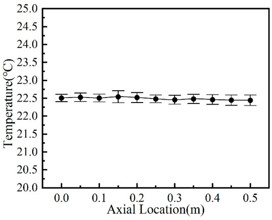
Figure 3.
Exterior wall and inlet and outlet temperatures of the 4 × 4 mm channel when it is not heated.
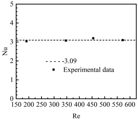
Figure 4.
Nusselt number of fully developed section at different Reynolds numbers.
3.2. Variation in Fluid Temperature and Wall Temperature in Single Phase and Two Phases
Figure 5 and Figure 6 show the changes in wall temperature and average fluid temperature along the channel axis under the single-phase and two-phase status in square and rectangular small channels. The figures indicate that the wall temperature in the two small channels with different cross-section shapes approximately presents a straight upward trend along the axial direction. This verifies that it is feasible to heat the outer wall of the channel by wrapping the resistance wire in the experiment. It can provide the channel’s wall with a consistent heat flux. In this experiment, the liquid Reynolds number is kept constant, and the uniform Taylor bubble is generated by changing the gas Reynolds number. The temperature of the fluid and channel wall are shown to be affected by two-phase flow at different Reynolds numbers, homogeneous void fraction and liquid slug lengths in Figure 5 and Figure 6. The figure demonstrates that at the same Reynolds number of the liquid phase, the injection of bubbles in the two-phase flow reduces the wall temperature at all positions in the axial direction compared with the single-phase flow. It is observed that along the axial direction, the temperature of the fluid under the two-phase diabatic intermittent flow (slug flow and bubble flow) is greater than single-phase flow. This is caused by local radial mixing caused by fluid slugs between bubbles. The fluid with higher temperature near the wall is brought into the central area because of the liquid slug’s internal circulation. So that the fluid is fully mixed, the temperature is more uniform and the fluid’s temperature is closer to the wall’s temperature. A larger convective heat transfer coefficient is obtained for these cases. Meanwhile, the thermal boundary layer’s thickness is lowered by the presence of the gas phase. The two-phase flow’s wall temperature will be lowered and the heat transfer will improve even more as a result of this. Under two-phase flow, the wall temperature decreased further and the fluid temperature rose as the gas Reynolds number increased, as depicted in Figure 5a,d and Figure 6a,d. Compared with the case of low gas Reynolds number in Figure 5a and Figure 6a, the radial mixing degree in the small channel increases as the gas Reynolds number rises. The radial mixing further reduces the wall temperature and increases the fluid temperature. As a conclusion, under such flow conditions, the annular vortex in the flowing slug will lead to the improvement of the heat transfer coefficient.
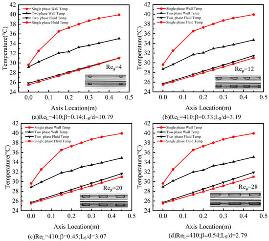
Figure 5.
Wall and fluid temperature variations in the square channel in the axial direction: (a) Reg = 4; (b) Reg = 12; (c) Reg = 20; (d) Reg = 28.
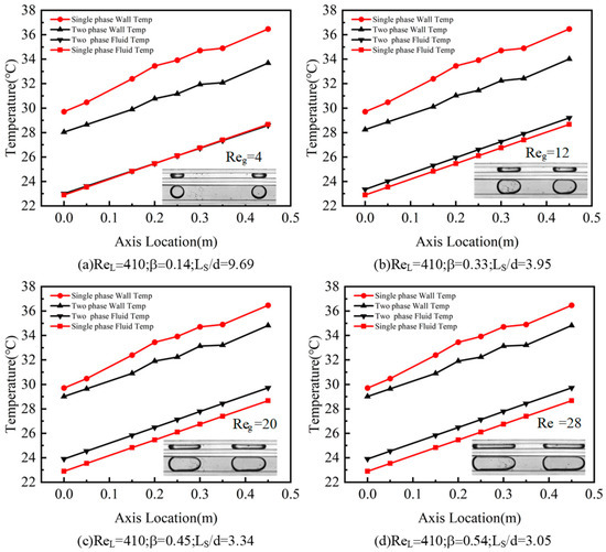
Figure 6.
Wall and fluid temperature variations in the rectangular channel in the axial direction: (a) Reg = 4; (b) Reg = 12; (c) Reg = 20; (d) Reg = 28.
3.3. Influence of Liquid Reynolds Number on Gas–Liquid Two-Phase Heat Transfer
Figure 7 and Figure 8 depict the variation in the average Nu number of two-phase intermittent air–water flow (bubble flow and slug flow) with Reynolds number of the liquid phase in small channels with two cross-section shapes, respectively. It can be clearly seen from these figures that in the two small channels, both the Nuave increase as the superficial liquid velocity rises. However, there is a slight difference in the change trend of the heat transfer coefficient in the two small channels under various superficial gas velocities.
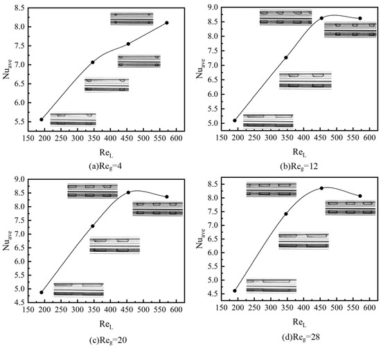
Figure 7.
Effect of liquid phase Reynolds number on heat transfer in square tube.
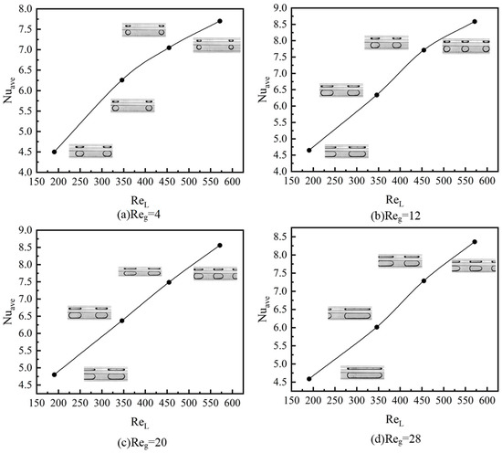
Figure 8.
Effect of liquid phase Reynolds number on heat transfer in rectangular tube.
The fluid’s disturbance increases as the liquid’s Reynolds number rises. There is improved heat transmission between the fluid and the tube wall. The heat transfer performance of two-phase flows in square and rectangular small channels is superior to that of single-phase flows at the same liquid Reynolds number. On the one hand, this is because, at the same liquid Reynolds number in two-phase flow, the disturbance of bubbles makes the fluid near the wall of the tube fully mixed with the fluid in the center of the tube, which decreased the difference in temperature between the wall and fluid temperature. Therefore, the heat transfer is enhanced. On the other hand, when the superficial liquid velocity is low at the laminar flow status for the single-phase flow, the thermal boundary layer formed near the channel wall is relatively thick while, for the two-phase flows, the dispersed gas has a good mixing effect with the liquid phase, which is conducive to reducing the thickness of the thermal boundary layer near the wall of the channel. Thus, the heat transfer enhancement is further realized.
However, the influence of liquid velocity on convective heat transfer in small channels with square and rectangular sections is not completely the same. In the square channel, the increase trend of Nuave increases sharply at first and then decreases slightly as the liquid Reynolds number increases. The increase in the liquid phase velocity is conducive to the increase in the heat transfer coefficient. However, the flow patterns also change with the increasing liquid phase velocity, as shown in Figure 7 and Figure 8. When the gas Reynolds number Reg is 12, 20 and 28, the average Nusselt number Nuave increases first and then decreases as the liquid Reynolds number rises, as depicted in Figure 7b–d. From the associated flow patterns, one can deduce that the liquid slug length is higher for the cases with ReL = 575 for Figure 7b–d. Longer slugs have longer radial circulation periods, so the frequency and intensity of radial circulation are lower, which weakens the radial mixing of fluid. The fluid in the center and close to the wall exchanges less heat. When the liquid slug’s length reaches infinity, single-phase flow performance comes near to being reached. The average Nusselt number of the square tube decreases when the heat transfer inhibition effect caused by the decrease in radial mixing degree is stronger than the heat transfer enhancement caused by the increase in increasing velocities. For rectangular channels, when the gas Reynolds number Reg is 4, 12, 20 and 28, the average Nusselt number always increases as the liquid Reynolds number rises, as depicted in Figure 8a–d. This is caused by the confined bubbles in the rectangular channels. As mentioned in Zhang et al. [16], the bubble shapes may change from axial symmetry when the mixture velocity is high, while the bubbles are always confined in the rectangular channels with non-axisymmetric shapes. For the cases studied in the present work, the confinement of the bubbles show an enhancement effect on the heat transfer coefficients. Besides this, the liquid slug gradually decreases with increasing ReL in the rectangular channels. As a conclusion, the different heat transfer performance between square and rectangular channels is mainly caused by the different flow patterns and bubble shapes.
In square and rectangular channels with constant heat flux boundary conditions, Figure 9 illustrates the local Nusselt number change in single-phase and two-phase diabatic Taylor flows. Along the flow direction, a higher Nusselt number results from the thermal boundary layer being thinner and the temperature gradient being greater near the entry section wall. In the fully developed section, the thermal boundary layer grows and the temperature gradient decreases. As a result, the Nusselt number decreases. The cold fluid in the center of the channel is periodically brought closer to the wall by recirculating vortices in the slug, which causes the Nusselt number to fluctuate. As depicted in Figure 9, when bubbles are added to two-phase flow, the Nusselt number is greatly affected and the heat transfer is significantly improved over single-phase flow.
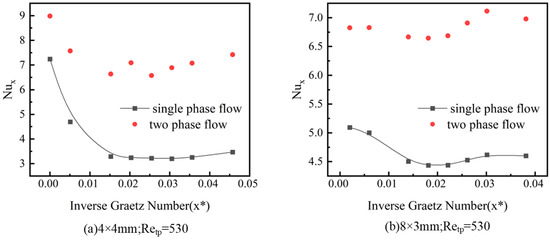
Figure 9.
Single-phase and two-phase local Nusselt numbers of square and rectangular cross-section channels.
3.4. Influence of Gas Reynolds Number on Gas–Liquid Two-Phase Heat Transfer
Figure 10 depicts the variation in normalized Nu* (ratio of average Nusselt number Nuave in two-phase to Nusselt number Nulo in the fully developed phase of single-phase water) of two-phase with gas Reynolds number in two kinds of cross-sectional small channels. As depicted in Figure 10, the Nu* is always greater than 1, which means that the addition of a dispersed bubble can enhance the heat transfer performance in square and rectangular channels. For the square channel, the Nu* ranges from 2.3 to 3.2, while this value ranges from 1.68 to 1.88 in rectangular channels. The heat transfer enhancement of rectangular channels is relatively lower than the square channels. The Nusselt number is not necessarily monotonic as the gas Reynolds number rises, because the increase in the gas Reynolds number may lead to the transition of the flow pattern. For the 4 × 4 mm channel, Nu* grows slowly when Reg exceeds 13, while the 8 × 3 mm channel still grows rapidly. Compared with the 4 × 4 mm channel, the aspect ratio of the 8 × 3 mm channel is larger, and, in the width direction, the bubbles are confined by the walls. However, it is not restricted in the length direction. The development of bubbles in the length direction leads to longer bubbles, shorter liquid plug length and a shorter radial mixing period in the 8 × 3 channel. Therefore, under the same ReL, the rectangular channel reaches the point of growth stagnation of Nu* later than the square channel. For the tube with a square section, when compared to single-phase flow, the Nusselt number of a gas–liquid flow can be raised by 3.2 times, since the liquid film of the rectangular tube is thicker at the corner of the channel and the thermal resistance is larger. At the same gas–liquid Reynolds number in the square tube, the two-phase flow has an average Nusselt number that is 1.87 times higher than the single-phase flow.
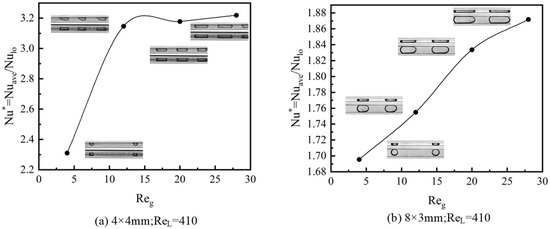
Figure 10.
Gas Reynolds number’s impact on improved heat transfer.
4. Conclusions
The characteristics of single-phase and two-phase heat transfer in square and rectangular small channels with constant heat flux are investigated experimentally in the present work. The main conclusions are as follows:
- Under two-phase flow, the axial wall temperature is lower at all locations than single-phase flow, while the axial fluid has a greater average temperature than single-phase flow.
- The heat transfer coefficients of the two-phase flow in the square and rectangular small channels are greater than those of the single phase in the same liquid Reynolds number. The length of the liquid slug and the thickness of the thermal boundary layer both have an impact on the variation trend in the heat transfer coefficient.
- The Nusselt number of the gas–liquid two-phase flow in the square-section channel can be increased by 3.2 times when compared to that in the single-phase flow, while the Nusselt number of the gas–liquid two-phase flow in the rectangular channel can be increased by 1.87 times when compared to that in the single-phase flow under the same gas–liquid Reynolds number.
Author Contributions
Conceptualization, N.Z. and J.Z.; methodology, B.Z. and L.L.; validation, L.L., C.C. and B.Z.; formal analysis, B.Z. and J.X.; investigation, B.Z. and J.X.; resources, J.Z.; data curation, B.Z.; writing—original draft preparation, B.Z. and N.Z.; writing—review and editing, L.L. and J.Z.; supervision, J.Z.; project administration, L.L. and J.Z.; funding acquisition, J.Z. All authors have read and agreed to the published version of the manuscript.
Funding
This work was funded by the Open Fund of Science and Technology on Thermal Energy and Power Laboratory (TPL2020B04), Shandong Provincial Natural Science Foundation (ZR2021ME080), Guangdong Basic and Applied Basic Research Foundation (2019A1515111116) and Foundation of Shandong University for Young Scholar’s Future Plans.
Data Availability Statement
Not applicable.
Acknowledgments
This work was funded by the Open Fund of Science and Technology on Thermal Energy and Power Laboratory (TPL2020B04), Shandong Provincial Natural Science Foundation (ZR2021ME080), Guangdong Basic and Applied Basic Research Foundation (2019A1515111116) and Foundation of Shandong University for Young Scholar’s Future Plans.
Conflicts of Interest
The authors declare no conflict of interest.
References
- Zhao, Q.; Ma, H.; Liu, Y.; Yao, C.; Yang, L.; Chen, G. Hydrodynamics and mass transfer of Taylor bubbles flowing in non-Newtonian fluids in a microchannel. Chem. Eng. Sci. 2021, 231, 116299. [Google Scholar] [CrossRef]
- Japar, W.M.A.A.; Sidik, N.A.C.; Mat, S. A comprehensive study on heat transfer enhancement in microchannel heat sink with secondary channel. Int. Commun. Heat Mass Transf. 2018, 99, 62–81. [Google Scholar] [CrossRef]
- Wang, Q.; Xu, B.; Huang, X.; Chen, Q.; Wang, H. Heat transfer and flow characteristics of straight-type PCHEs with rectangular channels of different widths. Nucl. Eng. Des. 2022, 391, 111734. [Google Scholar] [CrossRef]
- Scammell, A.; Kim, J. Heat transfer and flow characteristics of rising Taylor bubbles. Int. J. Heat Mass Transf. 2015, 89, 379–389. [Google Scholar] [CrossRef]
- Zhang, J.; Li, W. Investigation of hydrodynamic and heat transfer characteristics of gas–liquid Taylor flow in vertical capillaries. Int. Commun. Heat Mass Transf. 2016, 74, 1–10. [Google Scholar] [CrossRef]
- Wang, C.; Tian, M.; Zhang, J.; Zhang, G.; Zhang, Y. Numerical study on pressure drop and heat transfer characteristics of gas-liquid Taylor flow in a microchannel based on FFR method. Int. Commun. Heat Mass Transf. 2020, 117, 104802. [Google Scholar] [CrossRef]
- Eain, M.M.G.; Egan, V.; Punch, J. Local Nusselt number enhancements in liquid–liquid Taylor flows. Int. J. Heat Mass Transf. 2015, 80, 85–97. [Google Scholar] [CrossRef]
- Kumari, S.; Kumar, N.; Gupta, R. Flow and heat transfer in slug flow in microchannels: Effect of bubble volume. Int. J. Heat Mass Transf. 2019, 129, 812–826. [Google Scholar] [CrossRef]
- Shin, H.-C.; Kim, S.-M. Experimental investigation of two-phase flow regimes in rectangular micro-channel with two mixer types. Chem. Eng. J. 2022, 448, 137581. [Google Scholar] [CrossRef]
- Azadi, R.; Nobes, D.S. Local flow dynamics in the motion of slug bubbles in a flowing mini square channel. Int. J. Heat Mass Transf. 2021, 178, 121588. [Google Scholar] [CrossRef]
- Majumder, A.; Mehta, B.; Khandekar, S. Local Nusselt number enhancement during gas–liquid Taylor bubble flow in a square mini-channel: An experimental study. Int. J. Therm. Sci. 2013, 66, 8–18. [Google Scholar] [CrossRef]
- Mehta, B.; Khandekar, S. Measurement of local heat transfer coefficient during gas–liquid Taylor bubble train flow by infra-red thermography. Int. J. Heat Fluid Flow 2014, 45, 41–52. [Google Scholar] [CrossRef]
- Abdollahi, A.; Norris, S.E.; Sharma, R.N. Pressure Drop and Film Thickness of Liquid-Liquid Taylor Flow in Square Microchannels. Int. J. Heat Mass Transf. 2020, 156, 119802. [Google Scholar] [CrossRef]
- Abdollahi, A.; Norris, S.E.; Sharma, R.N. Fluid flow and heat transfer of liquid-liquid Taylor flow in square microchannels. Appl. Therm. Eng. 2020, 172, 115123. [Google Scholar] [CrossRef]
- Bayareh, M.; Esfahany, M.N.; Afshar, N.; Bastegani, M. Numerical study of slug flow heat transfer in microchannels. Int. J. Therm. Sci. 2020, 147, 106118. [Google Scholar] [CrossRef]
- Zhang, J.; Fletcher, D.F.; Li, W. Heat transfer and pressure drop characteristics of gas–liquid Taylor flow in mini ducts of square and rectangular cross-sections. Int. J. Heat Mass Transf. 2016, 103, 45–56. [Google Scholar] [CrossRef]
- Che, Z.; Wong, T.N.; Nguyen, N.-T.; Yang, C. Three dimensional features of convective heat transfer in droplet-based microchannel heat sinks. Int. J. Heat Mass Transf. 2015, 86, 455–464. [Google Scholar] [CrossRef]
- Talimi, V.; Muzychka, Y.; Kocabiyik, S. Slug flow heat transfer in square microchannels. Int. J. Heat Mass Transf. 2013, 62, 752–760. [Google Scholar] [CrossRef]
- Ferrari, A.; Magnini, M.; Thome, J.R. Numerical analysis of slug flow boiling in square microchannels. Int. J. Heat Mass Transf. 2018, 123, 928–944. [Google Scholar] [CrossRef]
- Abdollahi, A.; Sharma, R.N.; Vatani, A. Fluid flow and heat transfer of liquid-liquid two phase flow in microchannels: A review. Int. Commun. Heat Mass Transf. 2017, 84, 66–74. [Google Scholar] [CrossRef]
- Dai, Z.; Guo, Z.; Fletcher, D.F.; Haynes, B.S. Taylor flow heat transfer in microchannels—Unification of liquid–liquid and gas–liquid results. Chem. Eng. Sci. 2015, 138, 140–152. [Google Scholar] [CrossRef]
- Shah, R.K.; London, A.L. Laminar Flow Forced Convection in Ducts: A Source Book for Compact Heat Exchanger Analytical Data; Academic Press: Cambridge, MA, USA, 2014. [Google Scholar]
Publisher’s Note: MDPI stays neutral with regard to jurisdictional claims in published maps and institutional affiliations. |
© 2022 by the authors. Licensee MDPI, Basel, Switzerland. This article is an open access article distributed under the terms and conditions of the Creative Commons Attribution (CC BY) license (https://creativecommons.org/licenses/by/4.0/).