Abstract
Recently, the concept of the microgrid (MG) has been developed to assist the penetration of large numbers of distributed energy resources (DERs) into distribution networks. However, the integration of DERs in the form of MGs disturbs the operating codes of traditional distribution networks. Consequently, traditional protection strategies cannot be applied to MG against short-circuit faults. This paper presents a novel intelligent protection strategy (NIPS) for MGs based on empirical wavelet transform (EWT) and long short-term memory (LSTM) networks. In the proposed NIPS, firstly, the three-phase current signals measured by protective relays are decomposed into empirical modes (EMs). Then, various statistical features are extracted from the obtained EMs. Afterwards, the extracted features along with the three-phase current measurement are input to three different LSTM network to obtain exact fault type, phase, and location information. Finally, a trip signal based on the obtained fault information is generated to disconnect the faulty portion from the rest of the MG. The significant feature of the proposed NIPS is that it does not need adaptive relaying and communication networks. Moreover, it is independent of the operating scenario and hence fault current magnitude. To evaluate the efficacy of the proposed NIPS, exhaustive simulations are performed on an international electro-technical commission (IEC) MG. The simulation results confirm the efficiency of the proposed NIPs in terms of accuracy, dependability, and security. Moreover, comparisons with existing intelligent protection schemes validate that the proposed NIPS is highly accurate, secure, and dependable.
1. Introduction
Nowadays, increasing load demand, increasing concerns about global warming, and the latest advancements in renewable energy technology have led to a new trend in electricity generation [1,2]. These new power generation systems are usually integrated into the power system at distribution networks and represent distributed energy resources (DERs) [3,4]. To fully utilize the evolving potential of DERs, recently the concept of microgrid has been presented to integrate them into electrical distribution networks (EDNs).
A microgrid (MG) is generally regarded as a small part of a power network which incorporates a significant number of distributed generations, besides local loads and energy storage devices [5]. It is controlled and managed by intelligence and can operate in conjunction with the utility grid (grid-tied mode) in addition to being independent from the host grid (islanded mode). A MG is expected to guarantee a cost-effective service to the customer loads with superior quality and reliability in addition to the economical operation for its owner and auxiliary supply to the utility grid [6,7].
MGs have a high level of converter-interfaced DERs (CIDERs) penetration. The CIDERs have low inertia as compared to the rotating machines. The maximum current carrying capacity of CIDERs is limited, approximately two to three times that of rated current. This level of current is small as compared to the synchronous generators, which can provide current up to five to eight times their rated current [8]. Consequently, a MG has three major operating scenarios: (1) a grid-tied mode; (2) islanded mode with CIDERs, and (3); islanded mode with both synchronous-based DERs (SBDERs) and CIDERs [9].
MGs face significantly different levels of fault currents in each of the scenarios for a similar fault [10]. Thus, the conventional protection schemes, which assume the radial structure, high fault current level, and single mode operation, are inadequate for the protection of MGs. They may face problems such as nuisance tripping, blinding of protection, miss-coordination, and sensitivity loss if used for MGs [11]. Therefore, modifications in the traditional protection philosophies or new protection schemes are required to protect MGs.
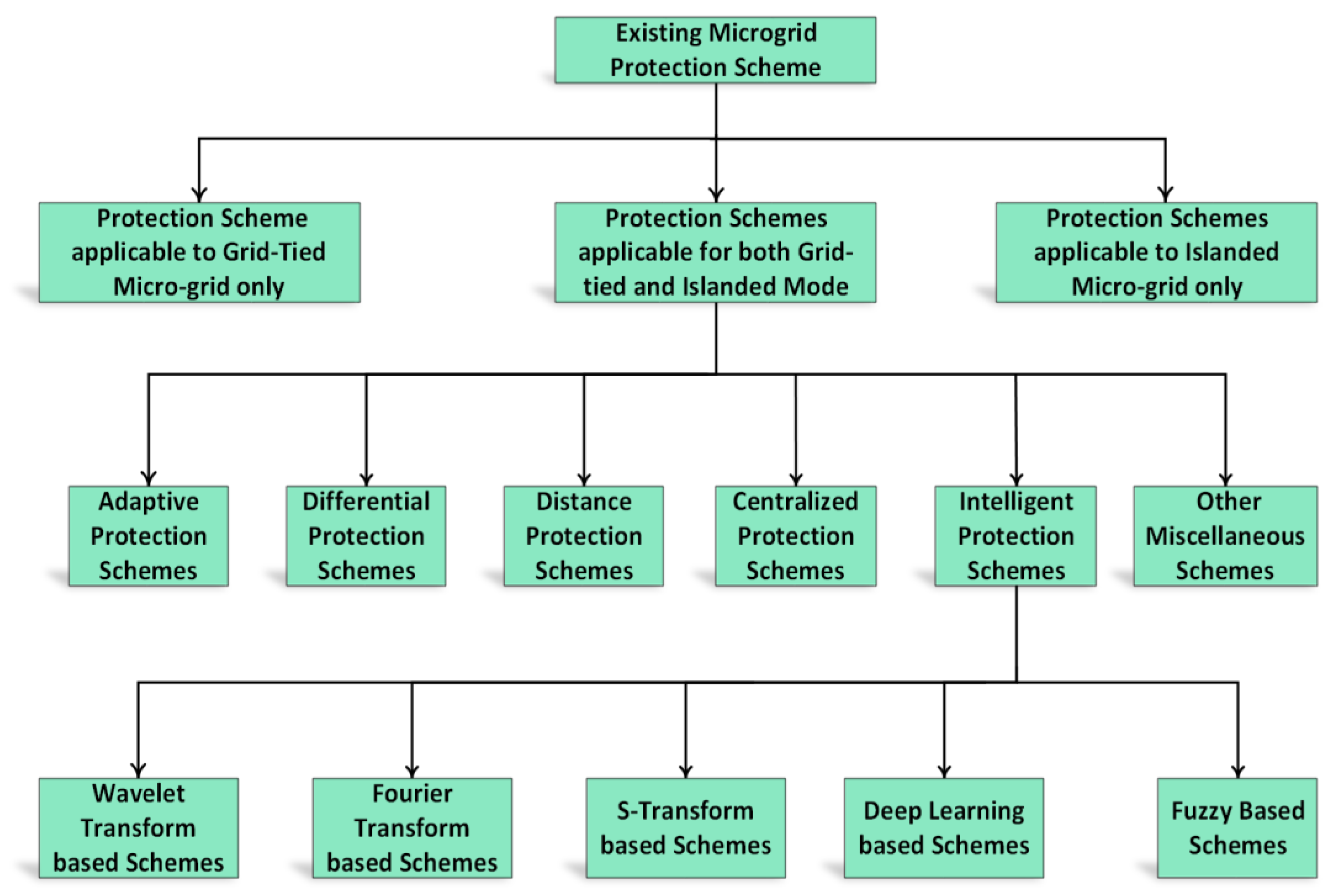
Various MG protection schemes have been developed and reported in the literature. A schematic classification of the existing MG protection schemes is shown in Figure 1. In ref. [12], the authors presented an intelligent agent-based protection strategy for radial and closed-loop distribution networks involving DERs. Communication links were developed between IEDs. The scheme was advantageous over traditional protection schemes as it offered higher speed backup protection. However, the scheme was prone to communication failure and was overall uneconomical. The authors in [13] developed a three-stage adaptive protection scheme for MGs. In the first and second stages, offline and online calculations of relay settings with DERs were performed, respectively. However, in the third stage, the adaptive relay settings were used for real-time protection of MGs. In ref. [14], a hybrid scheme based on adaptive and differential protection was presented. The seamless switching between the two schemes was obtained by a communication-assisted proactive process. In ref. [15], a communication-aided adaptive protection scheme has been presented to protect the islanded medium voltage CIDERs-based MG. The IEDs were employed to measure the current and voltage waveform. The current signal was used to detect the faults, while the voltage signal, along with the current signal, was used to identify the direction of faults in the islanded MG. In ref. [16], Oureilidi and Konstantinos protected the MGs by interchanging the control system of the converter. The faulty part was recognized by evaluating the fault current supplied by each converter. The authors in [17] developed a CPU-based centralized scheme to protect the radial and looped MGs in grid-tied and islanded modes of operations. All protection functions such as detection, location, classification, and trip signal generation were performed in the CPU. The trip signals were sent to relevant circuit breakers by the communication links. The fault components of positive sequence current and impedance were used for fault detection and fault location, respectively. A similar configuration was used for MG protection in [18]. However, the faults were detected using a combination of over-current and under-voltage relays. The fault location was achieved in two steps. In the first step, three buses closest to the fault point were selected by comparing the positive sequence voltage of all buses. Finally, the fault location index was calculated for all of the lines connected to the three buses; the line with a negative fault index was considered to be a faulty line.
Figure 1.
A schematic classification of the MG protection scheme.
The above-mentioned protection strategies cannot protect the MGs in all operating scenarios. The schemes that can protect MGs in all operating scenarios need a communication medium and synchronized measurement. Therefore, recently, many intelligent and signal processing-based MG protection strategies have been developed against various types of faults. In ref. [19], a statistical classifier-based differential protection strategy has been presented for islanded MGs. Several features from current and voltage signals were extracted at both terminals of a line in MGs. A data mining method was employed to pick the most suitable features. Finally, a differential operator was utilized to the selected features to identify and locate the faulty events in MGs. A time-frequency-based differential protection strategy has been presented in [20] for medium voltage MG with loop and radial network and CIDERs. In the suggested strategy, initially, the currents at both ends of the line were retrieved. Then, the spectral energy content of S-transform-based contours was computed. After that, the differential energy was obtained by calculating the difference of spectral energy computed at both ends of a line. The scheme was upgraded in [21] by suggesting the Hilbert-Huang transform for the calculation of the spectral energy instead of the s-transform due to the benefits of the Hilbert-Huang transform. In ref. [22], the initial travelling wave of current was extracted by mathematical morphology to identify the faults and their location. The scheme was used for islanded MG only. The authors in [23] used the wavelet transform to obtain the high-frequency components of current and voltage signals for radial MG protection. F. Costa et al. [24] developed a boundary wavelet transform-based protection for MGs. The time delay and instantaneous elements of the relay were calculated in the wavelet domain. A modified over-current relay was then employed to detect the faults in the grid-tied MG. In ref. [25], features were extracted by discrete wavelet transform. The extracted features were input into a data mining algorithm to detect and classify the faults in MGs. In ref. [6], the authors extracted various hidden features by using a matching pursuit algorithm. The extracted features were then provided to four different classifiers for fault detection and classification. Naive Bayes classifiers, along with the decision tree, were utilized to distinguish the faults in an islanded MG [26]. The authors in [9] used an interval type-2 fuzzy inference system to develop a new protection scheme for MG. Various fuzzy rules were defined for fault detection and fault direction identification. In ref. [1], a convolutional neural network-based protection scheme was presented for MGs. The scheme did not necessitate any external feature extractor for the intelligent classifier. Three different convolutional neural network structures were developed for fault detection, location, and classification. In ref. [27], discrete wavelet transform was employed to extract several fault features from the current signal; the deep neural network was then used to detect and classify the faults in MGs.
The above-presented protection schemes provided protection against various types of faults in MGs. However, each scheme has some limitations; some of the schemes only provided protection in one operating scenario. The scheme which provided protection in all scenarios required a communication medium, and hence was prone to communication failure. Additionally, some methods are only applicable to inverter-based DERs. Therefore, it is vital to design a new protection scheme for MGs that upholds its performance for all types of faults and operating conditions and DERs.
This paper presents a novel fast and intelligent strategy (NIPS) for the protection of MGs with multiple DERs against fault. The proposed NIPS uses EWT and LSTM to develop fault type, phase, and location information. First, the three-phase current signals are measured and sampled at the relay point. Next, the EWT, which is an adaptive time-frequency transform, is employed to decompose the current signals into EMs. Afterwards, several statistical features are extracted from the EMs. Later, the extracted features, along with the three-phase current measurements, are input into three different LSTMs for developing fault type, phase, and location information. Finally, based on the developed fault information, a trip signal is sent to the appropriate circuit breaker to isolate the faulty section from the rest of the MG. The main contributions of the paper are as follows:
- Intelligent Protection Strategy: A NIPS based on empirical wavelet EWT and LSTM is proposed that can protect MGs in all operating scenarios against short-circuit and high impedance faults.
- Adaptive Feature Extraction: Unlike existing protection schemes, the proposed scheme extracts the features from the fault signals using signal-adaptive filter banks. The wavelet filter banks in the EWT are built based on the information contained in the input signals.
- Communication-independent Strategy: The scheme does not require any communication networks for fault detection, classification or location, and it can be applied to any MG without significant modifications.
The rest of the paper is organized as follows: Section 2 and Section 3 provide the details of EWT and LSTM. The proposed NIPS is presented in Section 4. Section 5 provides the test system and fault data generation. Simulation results are presented in Section 6. Finally, the paper is synopsized in Section 7.
2. Empirical Wavelet Transform for Fault Signal Decomposition
The fault signals in the power system are non-stationary. Therefore, it is worthwhile to use time-frequency analyzing techniques to obtain the most appropriate features. In this study, the EWT transform is used to extract useful features from the three-phase current signals. The EWT is an adaptive non-stationary time-frequency analysis tool which decomposes a signal into EMs/frequency sub-bands [28,29]. Unlike a conventional wavelet transform, the EWT uses the information of the analyzed signal to design signal adaptive wavelet filters.
The three-phase current signals sampled by the protective relay are used as input to the EWT. The EWT is applied to each phase current independently. In EWT, firstly, the Fourier spectrum of the input signal is obtained. Then, the obtained Fourier spectrum is divided into N adjacent segments using the EWT boundary detection method. Afterwards, the empirical wavelets are defined as a band-pass filter on each segment by using the concept of Littlewoods-Paley and Meyer’s wavelet. Next, the empirical wavelets and scaling functions are obtained by using the following equations [28]:
where ω is the frequency; and ξ are the parameters which ensure that the empirical wavelet and scaling functions form a compact frame. These parameters are obtained by using the equations given in ref. [28]. Afterwards, the approximation and detail coefficients are determined from the inner product of the phase current with its corresponding wavelet and scaling functions.
Finally, these coefficients are utilized to obtain the EMs from the phase current.
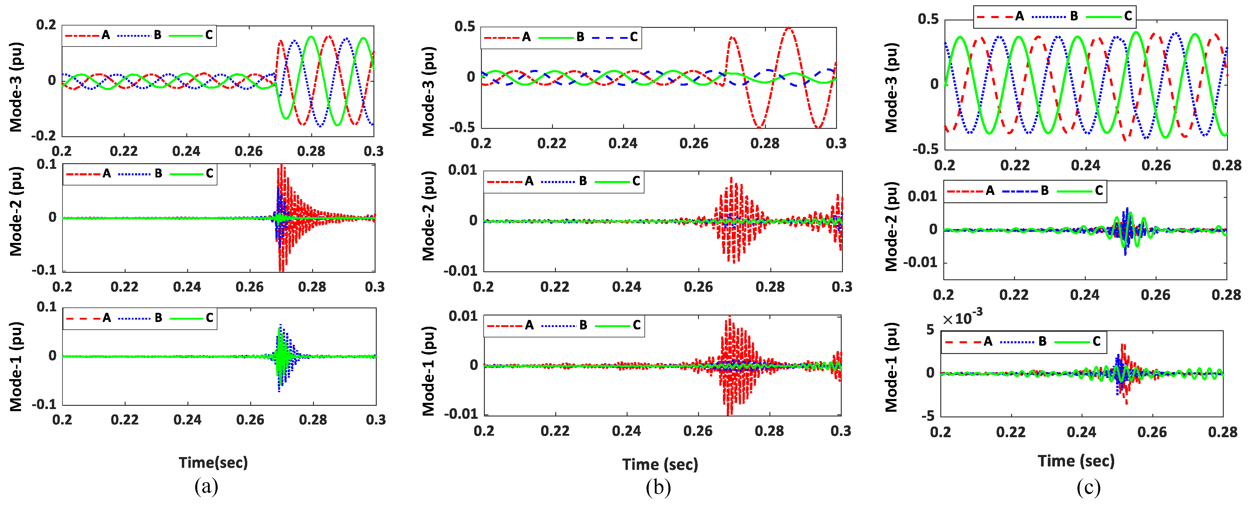
In this study, the first three EMs were used since most of the signal information is available in these modes. The result of the EWT decomposition of the three-phase current signal during a three-phase fault is shown in Figure 2a. It can be observed from the figure that the variation in the EMs is significant during the fault. The EWT sub-bands of the three-phase current signal for unbalanced faults (AG) are shown in Figure 2b. The figure shows a significant variation in the EMs of the faulty phase (A-phase) as compared to the healthy phases (B and C phase). Figure 2c shows the EMs of three-phase current when a capacitor bank is switched at 0.25 s. It can be observed from the results show that there are some variations in the EMs. However, these variations are minimal compared to the fault cases.
Figure 2.
First three EMs obtained during (a) three-phase current; (b) AG fault; (c) capacitor switching event.
From the above results, it can be concluded that the EWT decomposition can be applied to the fault signals for effective feature extraction. The adaptive nature of EWT can be useful to process the power system signals not only for transient analysis but also for estimation purposes.
Feature Extraction
Once the EMs of each phase are obtained, the next task is to extract discriminative features from the EMs for better performance of the proposed NIPS. In the proposed NIPS, several statistical features from the first three modes are extracted to develop the input feature vector for the LSTM networks. The reason for selecting three modes is that most of the signal information is available in the first three modes. Precisely, the following features are calculated from the first three EMs of each phase.
- The minimum value.
- The maximum value.
- The root-mean-square value.
- The energy of the EM.
- The standard deviation.
- The kurtosis.
- The skewness.
- The entropy of the EMs.
These features are extracted from the first three Ems. Therefore, for each cycle of the current 3 (EMs) × 8 (features) × 3 (phases) = 72 features are calculated. The generated features are later input into the LSTM network to develop the fault information.
3. Long Short-Term Memory Networks
An LSTM is a useful deep learning network, which is applied for sequential data processing. LSTM has the ability to extract long-term temporal features since it does not have a gradient vanishing problem. LSTM networks are widely utilized in the classification of time-series data due to their effectiveness [30,31].
The building block of LSTM networks is the memory units. The memory units are composed of memory cells which have self-joints. This helps the LSTMs to extract wide-range temporal features. The configuration of a simple LSTM memory unit is given in Figure 3. The basic memory unit has one cell for memory and three gates: (1) a forget gate, (2) an input gate, and (3) an output gate. The gates process the input data, update the memory cell and control the output information. An LSTM network relates the input and output sequences by computing the activation function for all nodes. In this study, the formulations of all nodes are taken from [30].
Figure 3.
Basic structure of an LSTM memory unit [1].
LSTM learn the relation between input and output datasets by supervised training. Generally fully connected (FC) layers are used at the end of LSTM layers to develop high-level decision logic for the extracted features. The FC layer contains a large number of neurons that maps the input to the output by using activation functions [30].
4. Proposed Protection Strategy
This paper proposes a NIPS for MGs using three-phase current data. The NIPS employs EWT and LSTM networks to develop fault information. The proposed NIPS has the ability to protect the looped and radial MGs against all types of short-circuit and high impedance faults in all operating scenarios. Firstly, the proposed NIPS takes three-phase currents at a relay as input. Then, the input signal at the relay point is processed through a second-order low-pass Butterworth filter with a cut-off frequency of 1500 Hz for antialiasing. The reason of selecting the value of 1500 Hz is that the 25th harmonic is the highest component of interest in the power system. Afterwards, the signal is sampled at a sampling rate of 3840 Hz. Next, the sampled signal is decomposed into EMs by EWT for feature extraction. Later, the extracted features, along with the three-phase current measurements, are input into three different units for developing fault type, phase, and location information. Finally, based on the developed fault information, a trip signal is sent to the appropriate circuit breaker to isolate the faulty section from the rest of the MG.
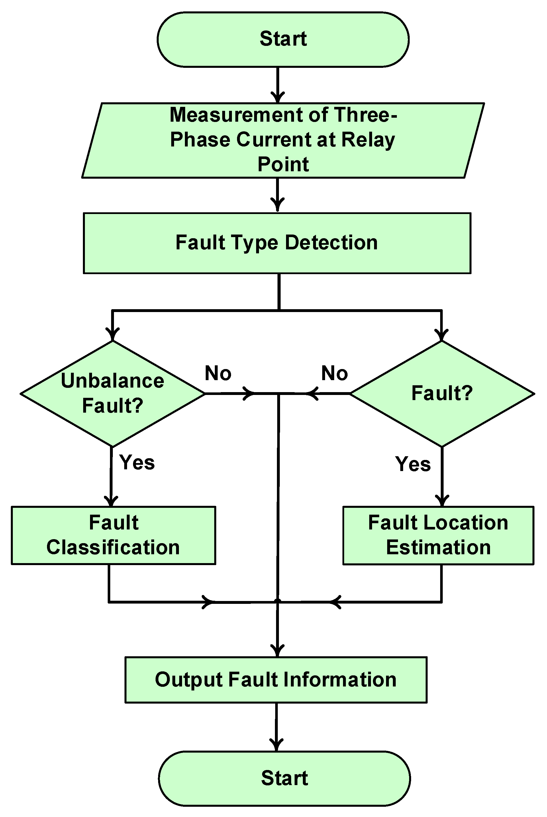
The flow chart of the proposed NIPS is given in Figure 4. The proposed FIPS has four key stages: signal measurement; fault type detection (FTD); fault classification; and fault location estimation. The subsequent subsections explain each stage of the proposed NIPS in detail.
Figure 4.
Flow chart of the proposed NIPS.
4.1. Fault Type Detection Unit
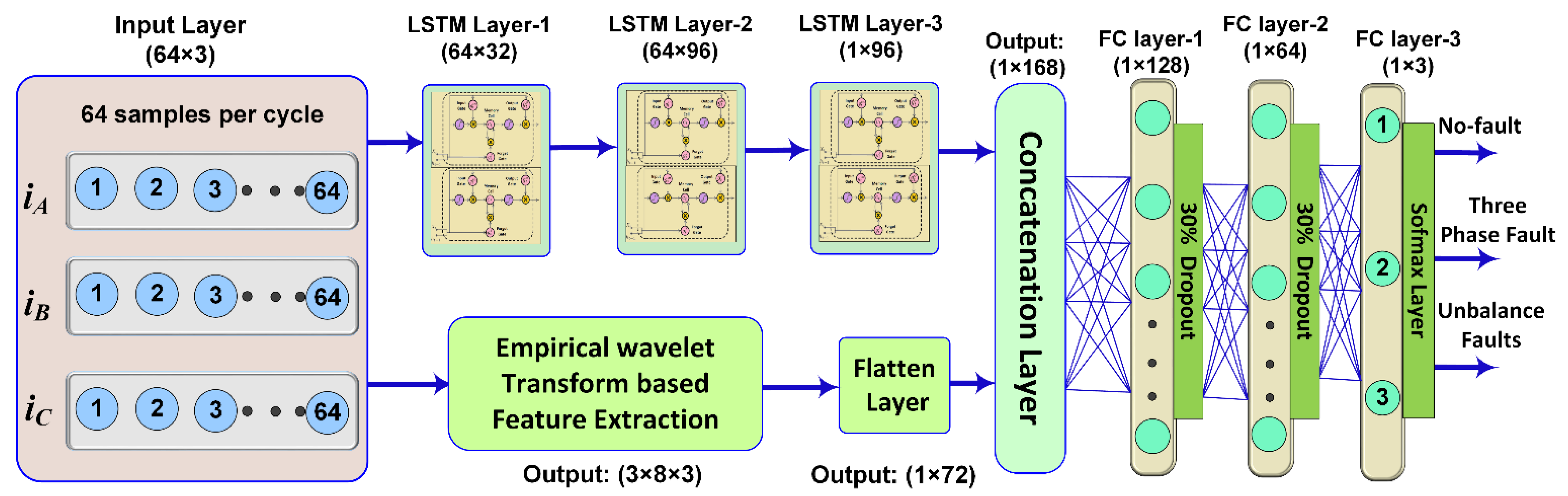
The FTD unit is responsible for detecting the fault type in the MGs. The schematic diagram of the FTD unit is shown in Figure 5. This input of this unit is the three-phase current which is classified among no-fault, three-phase fault, and unbalanced fault at the output. Each output has a 0/1 value, which denotes the status of outputs according to the following equation:
where FDTm denotes the output status of the mth fault type. The FTD unit employs three LSTM layers for temporal feature extraction and EWT for statistical feature extraction from the three-phase current signal. Among the three LSTM layers, the first layer maps the time-domain current signal into higher dimension space, whereas the next two layers are used to extract the long and short-term temporal dependencies. These LSTM layers are constructed using LSTM memory units. The dimensions of the layers are selected based on the number of input samples and the number of hidden neurons. After extracting features, a depth concatenation layer is used to combine LSTM-based features with EWT-based features. Afterwards, the features are abstracted by three FC layers. The number of hidden neurons in the first two FC layers is selected by performing extensive simulations, whereas the three hidden neurons are used in the last FC layer (which corresponds to three outputs). To avoid the risk of over-fitting, a dropout layer is employed after the first two FC layers, which exclude some features (30% in this study). The excluded features do not contribute to the output estimation. Lastly, a Softmax layer is used, which provides the most probable fault type at the output.
Figure 5.
Schematic diagram of fault type detection unit.
4.2. Fault Classification Unit
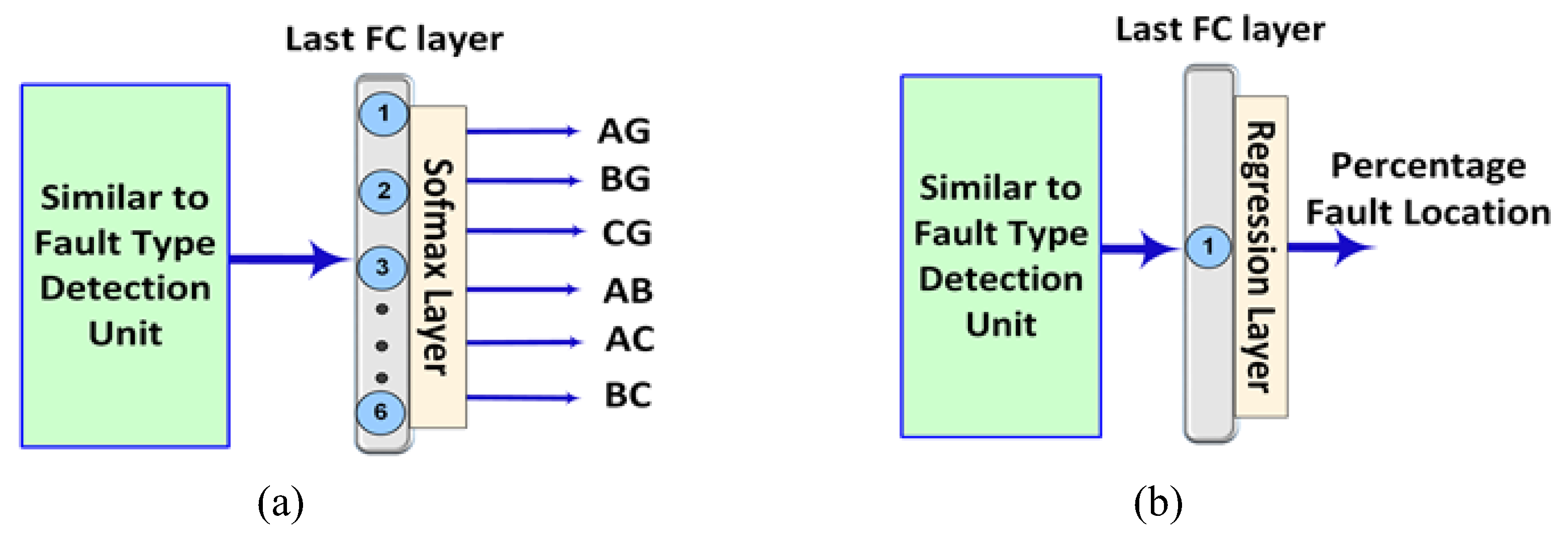
The fault type detection unit classifies the input signal among no-fault, three-phase fault, and unbalanced fault conditions. If the fault is detected as an unbalanced fault, then the fault classification unit is triggered. The fault classification unit employs LSTM and FC layers for fault classification. The structure of the fault classification unit is similar to that shown in Figure 5, except for the last FC layer. The block diagram of the modified structure is shown in Figure 6a. The last FC layer of the fault classification unit has six neurons, which corresponds to six unbalance faults. Each output has 0–1 indicators, which represent the status of each unbalance fault.
Figure 6.
Schematic diagram of (a) the fault classification unit and (b) the fault location estimation unit.
The fault classification unit works only for asymmetrical faults and classifies the input three-phase current into one of the six unbalanced faults.
4.3. Fault Location Estimation Unit
To reduce the blackout time and to increase the system repair, the precise location of the fault is important. The fault location estimation unit is developed to obtain the exact fault location in the proposed NIPS. This unit is triggered only if the fault type detection unit detects a three-phase or unbalanced fault in a MG. The fault location estimation unit also has a similar structure to that of the fault type detection unit except for the last FC layer and Softmax layer. The modified structure is shown in Figure 6b. The last FC layer in this unit has only one neuron as the regression layer relates the input data sample to continuous value. The objective function to be optimized during the training process of a network with a regression layer is the mean square error (MSE). The MSE can be calculated by using the following equation:
Here, MSE denotes the mean square error, n is the number of training samples, is the actual fault location and is the estimated location.
The fault location estimation unit uses a three-phase current at its input and maps it to one output. The output specifies the estimated percentage location of a fault in the MGs from the relay point.
5. Microgrid Test System and Fault Data Generation
To authenticate the efficacy of the proposed NIPS, several fault and non-fault conditions are investigated on IEC MG. The single-line diagram of the IEC MG is shown in Figure 7. The network and load-related data have been taken [32]. The nominal voltage of the system is 25 kV. The system integrates two CIDERs at buses B-4 and B-6 and two SBDERs at buses B-2 and B-3 by using step-up transformers. Three circuit breakers are used to create different working scenarios in the MG.
Figure 7.
IEC Microgrid.
To train the LSTM layers network with supervised learning, suitable prior data that represents fault/no-fault instances is important. In this study, the IEC MG was simulated in MATLAB/SIMULINK to produce the fault data for the training process of the LSTM networks. Simulations were executed for all ten types of faults under diverse fault locations, operating scenarios, network configuration, fault resistances, and loads. The details of the simulated fault conditions and no-fault conditions have been given in Table 1 and Table 2.
Table 1.
Simulated fault scenarios on the IEC MG test system.
Table 2.
Simulated non-fault scenarios on the IEC MG test system.
A total of 288 non-fault and 16,000 fault cases were generated in simulations. In each case, the three-phase currents signals were obtained at the relay point and then given to the proposed NIPS to obtain fault information. The obtained simulated data were randomly separated into training and testing datasets in the ratio of 3:1. The training dataset was used to train the learnable biases and weights of LSTM and FC layers.
6. Simulation Results and Discussion
6.1. Performance of Fault Type Detection
The two datasets obtained by simulation various fault and non-fault conditions were employed to train and test the LSTM network of the FTD unit. In the training phase, 10,080 samples of unbalanced faults, 1120 samples of three-phase faults, and 230 samples of no-fault (NF) were used. To remove the bias in the input samples, the non-fault samples and three-phase fault samples were replicated. The bias and weights of the structure were trained using the Adam optimization approach with a mini-batch size of 64. The percentage loss and accuracy during the training process of the fault type detection unit are shown in Figure 8. The figure shows that the training process converged fast within 23 epochs.
Figure 8.
Convergence curves of the fault type detection unit during the training process.
A confusion matrix is an effective method to demonstrate the performance of a multiclass intelligent classifier. The confusion matrices of the FTD unit during the grid-tied and islanding modes of operation are shown in Figure 9. The confusion matrix of grid-tied mode shows that all samples of the no faults and three-phase cases were correctly classified. In the case of unbalanced faults, 4 data samples, which constitute 0.2% of total data, were misclassified as a three-phase fault. Similarly, only one data sample of unbalanced faults was misclassified to no fault. Similarly, the confusion matrix of islanded mode depicts that 4 of the unbalanced fault data samples were incorrectly classified as a three-phase fault, whereas two three-phase fault data samples were miss-detected as unbalanced faults. In the case of the no-fault, the prediction accuracy is 100% (i.e., no other case was miss detected as NF and vice versa). The overall prediction accuracy of the FTD unit in grid-tied and islanded mode was 99.8% and 99.76%, respectively.
Figure 9.
Confusion matrices of the testing dataset for FTD unit during: (a) grid-tied mode and (b) islanded mode.
The results of the FTD unit of the proposed NIPS on each line of the IEC MG have been shown in Table 3. In the islanded mode, the FTD unit of NIPS attained 100% fault/no-fault accuracy. Furthermore, the results show that the proposed NIPS has the ability to give correct fault type information in most of the fault events.
Table 3.
FTD unit accuracy of the proposed FIPS on the IEC MG system.
6.2. Performance of Fault Classification Unit
The fault classification unit is activated when the FTD unit identifies an asymmetrical fault in the MG. The LSTM network of this unit was trained by using 2240 samples of each unbalanced fault. The loss and accuracy of the fault classification network during the training process are shown in Figure 10. The figure demonstrates that the training converged within 35 epochs.
Figure 10.
Convergence curves of the fault classification unit during the training process.
The performance of the fault classification unit during islanded and grid-tied modes is presented in Figure 11. In most of the unbalanced fault events, the fault classification unit of the proposed NIPS predicted an accurate class for the input data samples. Overall classification accuracy of 99.3% in grid-tied mode was observed, and only 15 out of 2160 fault events had incorrect classification information. In the islanded mode, the fault classification accuracy was more than 99.2%, and only 18 test samples had wrong fault classification.
Figure 11.
Confusion matrices of the testing dataset for fault classification unit during: (a) grid-tied mode; (b) islanded mode.
The results of the fault classification unit for each distribution line of the IEC MG are provided in Table 4. The results depict that the proposed NIPS accurately classified the asymmetrical faults in both islanded and grid-tied modes.
Table 4.
Fault classification accuracy of the proposed FIPS on the IEC MG system.
6.3. Performance of Fault Location Estimation Unit
This unit is triggered when the FTD unit identifies a fault in the MG. In the fault location estimation unit, the LSTM structure was trained to minimize the root-MSE between actual and estimated locations. To confirm the effectiveness of the proposed fault locator of NIPS, exhaustive simulations were executed at different locations in each distribution line and the results are shown in Table 5. The results demonstrate that the proposed NIPS provided a significantly accurate location of faults with a small error of 3.29% in islanded mode and 3.01% in grid-tied mode. This small error is acceptable as the length of the distribution lines in MGs is generally less than 20 km.
Table 5.
Perfomance of the fault location unit of the proposed NIPS on each line of the IEC MG.
6.4. Comparison with Existing Intelligent Schemes
Unlike the existing intelligent protection methods, the proposed NIPS uses signal adaptive filter banks to extract statistical features from the three-phase current signals. To confirm the effectiveness of the proposed NIPS, the obtained results are compared with the existing intelligent schemes using the same IEC MG. For this purpose, Convolutional neural network (CNN) [1], decision tree (DT) and support vector machine (SVM)-based schemes were selected [32]. Besides accuracy, two additional parameters, dependability and security, were used in the performance comparison. The parameters were obtained by the formula given in ref [1,32].
Table 6 provides the comparison of the proposed NIPS with CNN, SVM, and DT-based protection schemes. It is evident from the comparison results that the SVM has 99.03% detection accuracy (with 100% dependability and 98.06% security) in islanded mode whereas it has 98.33% accuracy (with 99.6% dependability and 97.06% security) in the grid-tied mode. For the same cases, CNN-based schemes provide 99.58% fault accuracy (with 98.89% dependability and 98.23% security) in islanded mode and 99.65% accuracy (with 100% dependability and 100% security) in grid-tied mode. Similarly, the DT was 99.02% accurate (with 99.8% dependability and 98.24% security) in the grid-tied mode and 99.47% accurate (with 99.60% dependability and 99.35% security) in islanded mode. The SVM and DT-based protection schemes did not offer fault location information. Moreover, they are prone to communication failure. On the other hand, the proposed NIPS offered an accuracy of 99.97% and security of 100% in both modes of operation.
Table 6.
Performance comparison of the proposed NIPS with existing intelligent schemes.
To validate the effectiveness in terms of operating time, the speed of operation of the proposed NIPS was also compared with already existing schemes. For this purpose, superimposed reactive energy (SRE) [11], interval type-2 fuzzy logic system (IT2FLS) [9] and CNN [1]-based MG protection schemes were selected. The comparison is given in Table 7. It can be observed from the table that the proposed NIPS provided better performance in terms of operating time as compared to SRE and IT2FLS-based schemes. Although the operating time of the proposed NIPS is the same as compared to CNN based protection scheme, the accuracy, dependability, and security are higher.
Table 7.
Comparison of operating time of the proposed NIPS with existing schemes.
In summary, the proposed NIPS has the ability to present fast and accurate fault type, phase and location information for MGs in different operating scenarios without any communication.
7. Conclusions
This paper presents a NIPS for MGs based on EWT and LSTM networks. The three-phase currents measurement were the input into the proposed NIPS, which processed them to provide complete information about the fault type, class, and location for the MGs. Precisely, the three-phase current signal was preprocessed using EWT, and various kinds of statistical features were obtained. Then, the phase currents, along with the extracted features, were used as input to the developed LSTM networks to detect, classify, and locate the faults within the MGs. To evaluate the effectiveness of the proposed scheme, exhaustive simulations were carried out on a standard IEC MG test system. The results demonstrated that the proposed NIPS successfully developed correct fault information for all of the lines in the MG. The fault type detection unit of the proposed NIPS achieved an overall accuracy of 99.76% in the grid-tied mode and 99.70% in the islanded mode. The fault classification accuracy of the proposed scheme was 99.30% in both modes of operation. The proposed scheme estimated quite precise fault location for all distribution lines of the MG, resulting in 3.01% and 3.29% mean square error for grid-tied and islanded modes, respectively. The scheme provided exact fault type, phase, and location information as compared to the advanced fault detection schemes in the literature for a similar test system. In summary, the proposed NIPS can be used to detect, classify, and locate different types of faults within radial and looped MGs in both modes of operation, which will ensure the safe operation of MGs.
Author Contributions
Conceptualization, S.B.A.B., A.W. and T.K.; Data curation, K.K.M. and S.B.R.; Formal analysis, A.W. and K.K.M.; Funding acquisition, A.W., K.K.M., S.B.R. and K.-C.K.; Investigation, S.B.A.B.; Methodology, S.B.A.B. and T.K.; Resources, A.W. and S.B.R.; Supervision, S.B.R. and K.-C.K.; Visualization, T.K.; Writing—original draft, S.B.A.B. All authors have read and agreed to the published version of the manuscript.
Funding
This work was supported by the 2022 Yeungnam university Research grant.
Conflicts of Interest
The authors declare no conflict of interest.
Abbreviations
The following abbreviations were used in this paper.
| CIDERs | Converter interfaced distributed energy resources |
| CNN | Convolution neural network |
| CPU | Central processing unit |
| DERs | Distributed energy resources |
| DL | Distribution line |
| DT | Decision tree |
| EDNs | Electrical distribution networks |
| EWT | Empirical wavelet transform |
| EMs | Empirical modes |
| FC | Fully connected |
| FTD | Fault type detection |
| IEC | International Electrotechnical Commission |
| IEDs | Intelligent electronic devices |
| LSTM | Long-short term memory network |
| MG | Microgrid |
| MSE | Mean square error |
| NIPS | Novel intelligent protection scheme |
| NF | No fault |
| SBDERs | Synchronous-based distributed energy resources |
| SVM | Support vector machine |
| TP | Three phase faults |
| UF | Unbalanced faults |
| ω | frequency in rad/sec |
| Ψi(ω) | Empirical wavelet function |
| ϕiω | Empirical scaling function |
| β, ξ | Parameters which ensure the compact frame for empirical wavelet and scaling function |
| y0(t) | Approximation coefficient at time t |
| yk(t) | Kth detailed coefficient at time t |
| FDTm | Output status of the mth fault type |
| Lactual | Actual fault location |
| Lest. | Estimated fault location |
| n | Number of training samples |
References
- Bukhari, S.B.A.; Kim, C.-H.; Mehmood, K.K.; Haider, R.; Saeed Uz Zaman, M. Convolutional Neural Network-Based Intelligent Protection Strategy for Microgrids. IET Gener. Transm. Distrib. 2020, 14, 1177–1185. [Google Scholar] [CrossRef]
- Mishra, M.; Patnaik, B.; Biswal, M.; Hasan, S.; Bansal, R.C. A Systematic Review on DC-Microgrid Protection and Grounding Techniques: Issues, Challenges and Future Perspective. Appl. Energy 2022, 313, 118810. [Google Scholar] [CrossRef]
- Beheshtaein, S.; Savaghebi, M.; Vasquez, J.C.; Guerrero, J.M. Protection of AC and DC Microgrids: Challenges, Solutions and Future Trends. In Proceedings of the IECON 2015-41st Annual Conference of the IEEE Industrial Electronics Society, Yokohama, Japan, 9–12 November 2015; pp. 005253–005260. [Google Scholar]
- Bukhari, S.B.A.; Mehmood, K.K.; Wadood, A.; Park, H. Intelligent Islanding Detection of Microgrids Using Long Short-Term Memory Networks. Energies 2021, 14, 5762. [Google Scholar] [CrossRef]
- Zamani, M.A.; Yazdani, A.; Sidhu, T.S. A Communication-Assisted Protection Strategy for Inverter-Based Medium-Voltage Microgrids. IEEE Trans. Smart Grid 2012, 3, 2088–2099. [Google Scholar] [CrossRef]
- Abdelgayed, T.S.; Morsi, W.G.; Sidhu, T.S. A New Approach for Fault Classification in Microgrids Using Optimal Wavelet Functions Matching Pursuit. IEEE Trans. Smart Grid 2018, 9, 4838–4846. [Google Scholar] [CrossRef]
- Beheshtaein, S.; Cuzner, R.; Savaghebi, M.; Guerrero, J.M. Review on Microgrids Protection. IET Gener. Transm. Distrib. 2019, 13, 743–759. [Google Scholar] [CrossRef]
- Nimpitiwan, N.; Heydt, G.T.; Ayyanar, R.; Suryanarayanan, S. Fault Current Contribution from Synchronous Machine and Inverter Based Distributed Generators. IEEE Trans. Power Deliv. 2007, 22, 634–641. [Google Scholar] [CrossRef]
- Bukhari, S.B.A.; Haider, R.; Zaman, M.S.U.; Oh, Y.-S.; Cho, G.-J.; Kim, C.-H. An Interval Type-2 Fuzzy Logic Based Strategy for Microgrid Protection. Int. J. Electr. Power Energy Syst. 2018, 98, 209–218. [Google Scholar] [CrossRef]
- Giraldo, J.; El Hariri, M.; Parvania, M. Decentralized Moving Target Defense for Microgrid Protection Against False-Data Injection Attacks. IEEE Trans. Smart Grid 2022, 13, 3700–3710. [Google Scholar] [CrossRef]
- Bukhari, S.B.A.; Zaman, M.S.U.; Haider, R.; Oh, Y.-S.; Kim, C.-H. A Protection Scheme for Microgrid with Multiple Distributed Generations Using Superimposed Reactive Energy. Int. J. Electr. Power Energy Syst. 2017, 92, 156–166. [Google Scholar] [CrossRef]
- Liu, Z.; Su, C.; Høidalen, H.K.; Chen, Z. A Multiagent System-Based Protection and Control Scheme for Distribution System with Distributed-Generation Integration. IEEE Trans. Power Deliv. 2017, 32, 536–545. [Google Scholar] [CrossRef]
- Teimourzadeh, S.; Aminifar, F.; Davarpanah, M.; Shahidehpour, M. Adaptive Protection for Preserving Microgrid Security. IEEE Trans. Smart Grid 2017, 10, 592–600. [Google Scholar] [CrossRef]
- Ustun, T.S.; Khan, R.H. Multiterminal Hybrid Protection of Microgrids over Wireless Communications Network. IEEE Trans. Smart Grid 2015, 6, 2493–2500. [Google Scholar] [CrossRef]
- Zamani, M.A.; Sidhu, T.S.; Yazdani, A. A Communication-Based Strategy for Protection of Microgrids with Looped Configuration. Electr. Power Syst. Res. 2013, 104, 52–61. [Google Scholar] [CrossRef]
- Oureilidis, K.O.; Demoulias, C.S. A Fault Clearing Method in Converter-Dominated Microgrids with Conventional Protection Means. IEEE Trans. Power Electron. 2016, 31, 4628–4640. [Google Scholar] [CrossRef]
- Mirsaeidi, S.; Said, D.M.; Mustafa, M.W.; Habibuddin, M.H.; Ghaffari, K. Fault Location and Isolation in Micro-Grids Using a Digital Central Protection Unit. Renew. Sustain. Energy Rev. 2016, 56, 1–17. [Google Scholar] [CrossRef]
- Bukhari, S.B.A.; Haider, R.; Zaman, M.S.; Oh, Y.S.; Cho, G.J.; Kim, M.S.; Kim, J.S.; Kim, C.H. Adaptive Centralized Protection Scheme for Microgrids Based on Positive Sequence Complex Power. In Proceedings of the International Conference on Power Systems Transient, Seoul, Korea, 26–29 June 2017. [Google Scholar]
- Casagrande, E.; Woon, W.L.; Zeineldin, H.H.; Svetinovic, D. A Differential Sequence Component Protection Scheme for Microgrids With Inverter-Based Distributed Generators. IEEE Trans. Smart Grid 2014, 5, 29–37. [Google Scholar] [CrossRef]
- Kar, S.; Samantaray, S.R. Time-Frequency Transform-Based Differential Scheme for Microgrid Protection. IET Gener. Transm. Distrib. 2014, 8, 310–320. [Google Scholar] [CrossRef]
- Gururani, A.; Mohanty, S.R.; Mohanta, J.C. Microgrid Protection Using Hilbert–Huang Transform Based-Differential Scheme. IET Gener. Transm. Distrib. 2016, 10, 3707–3716. [Google Scholar] [CrossRef]
- Li, X.; Dyśko, A.; Burt, G.M. Traveling Wave-Based Protection Scheme for Inverter-Dominated Microgrid Using Mathematical Morphology. IEEE Trans. Smart Grid 2014, 5, 2211–2218. [Google Scholar] [CrossRef] [Green Version]
- Saleh, S.A. Signature-Coordinated Digital Multirelay Protection for Microgrid Systems. IEEE Trans. Power Electron. 2014, 29, 4614–4623. [Google Scholar] [CrossRef]
- Costa, F.B.; Monti, A.; Paiva, S.C. Overcurrent Protection in Distribution Systems with Distributed Generation Based on the Real-Time Boundary Wavelet Transform. IEEE Trans. Power Deliv. 2017, 32, 462–473. [Google Scholar] [CrossRef]
- Mishra, D.P.; Samantaray, S.R.; Joos, G. A Combined Wavelet and Data-Mining Based Intelligent Protection Scheme for Microgrid. IEEE Trans. Smart Grid 2016, 7, 2295–2304. [Google Scholar] [CrossRef]
- Casagrande, E.; Woon, W.L.; Zeineldin, H.H.; Kan’an, N.H. Data Mining Approach to Fault Detection for Isolated Inverter-Based Microgrids. IET Gener. Transm. Distrib. 2013, 7, 745–754. [Google Scholar] [CrossRef]
- James, J.Q.; Hou, Y.; Lam, A.Y.; Li, V.O. Intelligent Fault Detection Scheme for Microgrids with Wavelet-Based Deep Neural Networks. IEEE Trans. Smart Grid 2017, 10, 1694–1703. [Google Scholar]
- Gilles, J. Empirical Wavelet Transform. IEEE Trans. Signal Process. 2013, 61, 3999–4010. [Google Scholar] [CrossRef]
- Thirumala, K.; Umarikar, A.C.; Jain, T. Estimation of Single-Phase and Three-Phase Power-Quality Indices Using Empirical Wavelet Transform. IEEE Trans. Power Deliv. 2015, 30, 445–454. [Google Scholar] [CrossRef]
- Chemali, E.; Kollmeyer, P.J.; Preindl, M.; Ahmed, R.; Emadi, A. Long Short-Term Memory Networks for Accurate State-of-Charge Estimation of Li-Ion Batteries. IEEE Trans. Ind. Electron. 2018, 65, 6730–6739. [Google Scholar] [CrossRef]
- Kong, W.; Dong, Z.Y.; Jia, Y.; Hill, D.J.; Xu, Y.; Zhang, Y. Short-Term Residential Load Forecasting Based on LSTM Recurrent Neural Network. IEEE Trans. Smart Grid 2017, 10, 841–851. [Google Scholar] [CrossRef]
- Kar, S.; Samantaray, S.R.; Zadeh, M.D. Data-Mining Model Based Intelligent Differential Microgrid Protection Scheme. IEEE Syst. J. 2017, 11, 1161–1169. [Google Scholar] [CrossRef]
Publisher’s Note: MDPI stays neutral with regard to jurisdictional claims in published maps and institutional affiliations. |
© 2022 by the authors. Licensee MDPI, Basel, Switzerland. This article is an open access article distributed under the terms and conditions of the Creative Commons Attribution (CC BY) license (https://creativecommons.org/licenses/by/4.0/).