Article

Experimental Study on the Contact Force between the Vessel and CBF in the Integrated Floating Transportation Process of Offshore Wind Power †

1
School of Civil Engineering, Tianjin University, Tianjin 300072, China
2
State Key Laboratory of Hydraulic Engineering Simulation and Safety, Tianjin University, Tianjin 300072, China
*
Author to whom correspondence should be addressed.
This paper is an extended version of our paper published in 37th ASME International Conference on Ocean, Offshore and Arctic Engineering Conference, Madrid, Spain, 17–22 June 2018.
Energies 2022, 15(21), 7970; https://doi.org/10.3390/en15217970
Submission received: 4 August 2022 / Revised: 9 October 2022 / Accepted: 24 October 2022 / Published: 27 October 2022
(This article belongs to the Section A3: Wind, Wave and Tidal Energy)

Abstract

:
More and more clean energy is used worldwide and offshore wind power is an important part of clean energy. The difficulty of offshore construction is an important problem. The integrated floating transport technique of composite bucket foundation (CBF) provides an important method to solve this problem. The main purpose of this paper is to study and verify the safety of the integrated floating transport technique of the composite bucket foundation. Through the test method, we determine the location distribution where the contact force changes greatly and identify the factors that have a great impact on the contact force. We study the influencing factors of the contact force between the composite bucket foundation and the installation vessel during the towing process and verify the experimental results through project data monitoring. We conclude by proposing feasible suggestions for the safety assurance of the project based on the contact force problem.

1. Introduction

The stock of fossil fuels is limited and they can cause significant pollution to the environment, while wind energy is a renewable and clean energy source. To achieve the goal of lower pollution with a longer service life in energy production, wind energy is increasingly being utilized. The proportion of wind power generation in the world has increased significantly (Figure 1a,b). By 2020, China’s offshore wind power installed capacity reached 30 GW. In Europe, where offshore wind power is widely used, 100 GW of offshore wind farms will have been built by 2020. Approximately 93 GW of new wind power was installed globally in 2020; 53% more than 2019, and the total installed capacity worldwide reached 742 GW [1,2,3,4,5]. Today, offshore wind power has been widely used, but there is still a problem of high transportation and installation costs (about twice the cost of onshore wind power installation). In addition, the safety of offshore construction is still an urgent problem to be solved.
Complex marine conditions and the seabed make it difficult to solve the problem of offshore construction, thus contributing to the high price of offshore wind power: the unit price of offshore wind power in Europe is about EUR 0.15, while the unit price of onshore wind power is about EUR 0.07/kWh. Therefore, reducing the offshore construction period is one of the important challenges in offshore wind power application, and the optimization of the form of the offshore wind power foundation can effectively achieve this. The common foundation forms of offshore wind power include mono-pile foundation, multi-pile cap foundation, gravity foundation, bucket foundation, jacket foundation, and floating foundation. These foundation forms have their own advantages, but also have their own applicable water depth, seabed, fan capacity, etc. [6,7,8,9,10,11,12,13,14,15].
In a word, the common problem of these foundations is the difficulty of offshore construction, which leads to long construction time and high cost. Under such conditions, the composite bucket foundation (CBF) was developed. It combines the traditional bucket foundation with the gravity foundation, and has the advantages of onshore manufacturing and assembly, integrated transportation and installation, and is reusable. In particular, it provides an effective solution to the problems of high construction costs and long construction time, that is, the integrated floating transport and installation technique of composite bucket foundation. So far, the first offshore wind turbine using CBF has been operating safely for 10 years, which indicates that CBF can meet the requirements of an offshore wind turbine foundation [16,17,18,19,20,21,22].
For the transportation of offshore wind turbines, many scholars have carried out research on this topic. Collu et al. took a real floating body as the research object for analyzing offshore wind power in the transportation and installation process. Ding et al. and Zhang et al. studied the property of bucket foundation by simulation and experimental research methods. Han et al. studied the stability of integrated bucket foundations in the process of wet towing by a large-scale test. Completion of offshore transportation and installation together can greatly reduce the offshore construction time and optimize the construction cost and safety [23,24,25,26,27].
The main features of the CBF are onshore integral construction and offshore one-step installation; these two processes are an integral whole. As shown in Figure 2, the CBF and one-step integrated installation techniques for offshore wind turbine are described in order to better illustrate the characteristics of this structure.
Traditional offshore wind power mostly completes the construction process offshore, while the integrated floating transport technique of offshore wind turbines with CBF completes most of the construction onshore. The integrated floating transport technique of offshore wind turbines with CBF simplifies the construction steps, and the construction time on the sea is greatly reduced as a result. Firstly, the construction of the bottom steel bucket and the concrete transitional segment should be fabricated on land, and these two parts are joined by welding. Secondly, the sinking position is next to the pier during the lifting of the CBF into water with the 5000 T gantry crane, and sinking the CBF in place through suction. Thirdly, the wind turbine tower and generator are installed near the pier. Fourthly, the whole structure is shipped on the maritime transport and installation ship, and is transported to the designated location. Finally, using the negative pressure technology, the installation tasks of two CBF can be finished at once. At present, this installation technology has been applied in practice in China (Figure 3) [25,26,28,29,30,31,32,33,34,35].
In order to further verify the safety of this technique, the wholeness of the vessel and CBF must be confirmed, which means that the vessel and CBF cannot be separated. This requires the study of the contact force between the vessel and CBF. Therefore, model tests were conducted to study the contact force between the vessel and CBF during the towing operation.

2. Model Test Setup

The tests are based on a 1:50 scaled vessel and CBF model which is made of plexiglass. As long as it is properly maintained, plexiglass can maintain better water tightness for a long time. The geometric dimensions of the model and the prototype are reduced by 1:50, but because of the different materials from the prototype, the weight at the center of gravity is used to achieve the weight scale. Due to the transparency of plexiglass, the use of plexiglass can better observe the vessel’s draft and the relative position changes between the CBF and thus determines the ship interaction between the CBF. The structure and mass distribution of the scaled model are consistent with the prototype. Froude’s scaling laws are applied in the model test. The vessel model is 2.064 m long and each bucket model has a diameter of 0.7 m and a height of 0.23 m, other sizes are summarized in Table 1 and Table 2. The towing tank is about 130 m long, 7 m wide, and 6–9 m deep at Tianjin University.
As shown in Figure 4a, the whole model (vessel and CBF) is placed in water. In order to install the CBF, there is a groove on each side of the vessel. There are 7 cabins inside the CBF and they are used to compress the air inside to provide buoyancy (Figure 4c,d). Each cabin has an opening at the bottom. Air will be injected into the cabins and the bottom will be closed by the water surface. Each CBF is floated on the water and then self-floats to the concaved bottom of the vessel by the pressure resulting from compressed air inside the cabins (Figure 4a). Two towing points are set at the front of the vessel and at the same height as the deck. The other end of the towing bridle is attached to the trailer above the towing tank. The height of the trailer is the same as the towing points (Figure 4b).
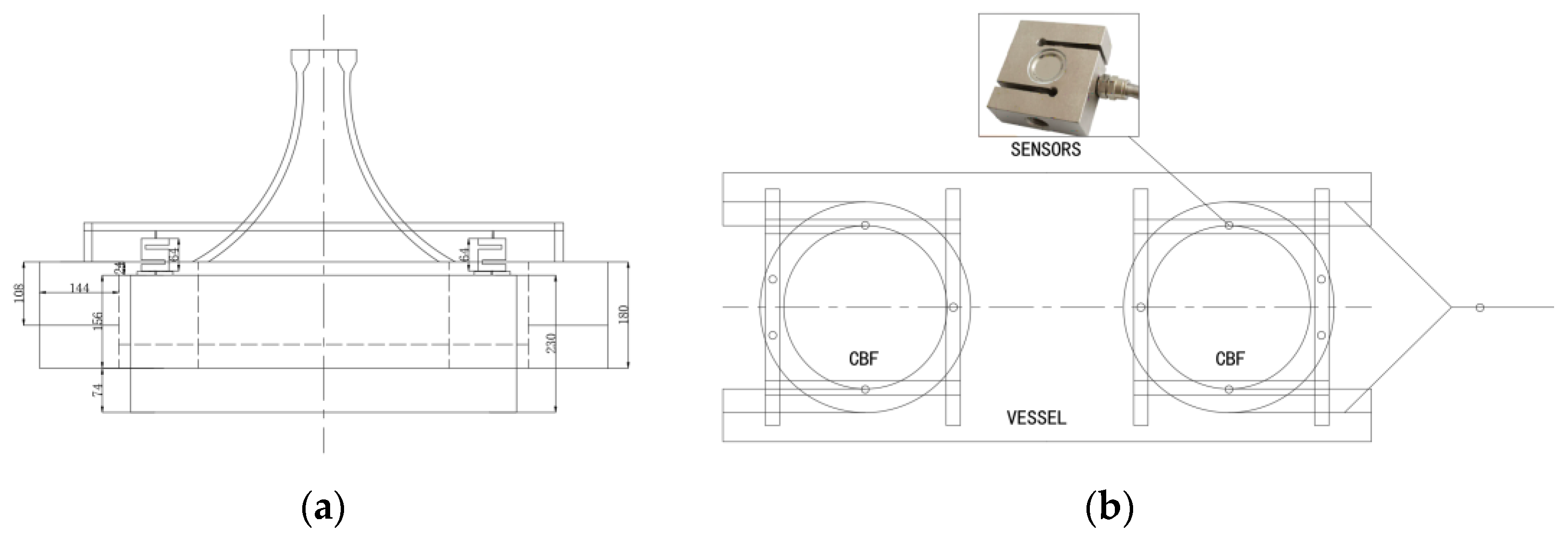
The sensors used in the model test are one-way type-S tension pressure sensors. The vertical contact force between the vessel and the CBF is measured by the sensors which connect the vessel to the CBF. In the experiment, the wave is regular, and the wave direction angle is 180°. To measure the vertical force between CBF and the installation vessel more accurately, the sensor is rigidly connected with the vessel. Five sensors are arranged on each CBF, and the positions of the measuring points are shown in Figure 5. In order to clearly obtain the contact force during towing, the data measured by the sensor are reset before towing. In order to directly obtain the contact force, no pre-tension is provided in this experiment. Then, the final measured data are the contact force during towing. The test data are collected during the towing process.

3. Results and Interpretation

3.1. Working Condition Arrangement

The control factors in the model test include wave height, towing speed, and draft. The specific parameters are selected in Table 3 below. A total of 60 groups of tests were completed. In the experiment, the wave is regular, and the wave direction angle is 180°. The appropriate working conditions will be selected for analysis.

3.2. Effect of Bow and Stern

Firstly, the contact force between the vessel and CBF at the bow and stern is analyzed.
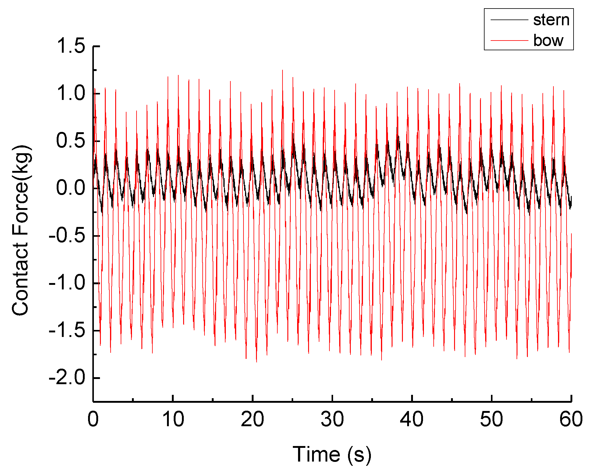
The test conditions are shown in Table 4. Once the model motion state became stable, the results for the contact force between the vessel and CBF (Figure 6) were extracted for a period of 60 s. The figure shows the difference of the contact force between the bow and stern of the vessel and CBF during wet towing. It can be seen from the figure that the stern contact force is between ±0.5 kg, while the bow contact force changes are between −1.7 kg and 1.2 kg. The contact force of the bow facing the wave is much greater than that of the stern. The contact force fluctuation of the bow facing the wave is also much larger than that of the stern. The contact force period of bow and stern is consistent, which indicates that the integrity of the vessel and CBF is consistent during towing. Based on the above experimental results, the limit conditions are more valuable for safety research, and the bow data are selected in the following analysis.

3.3. Effect of Wave Height

Taking the wave height as the main variable, and keeping the factors except for wave height unchanged, we can combine the following conditions (Table 5); the values in the table are the model-scale values.
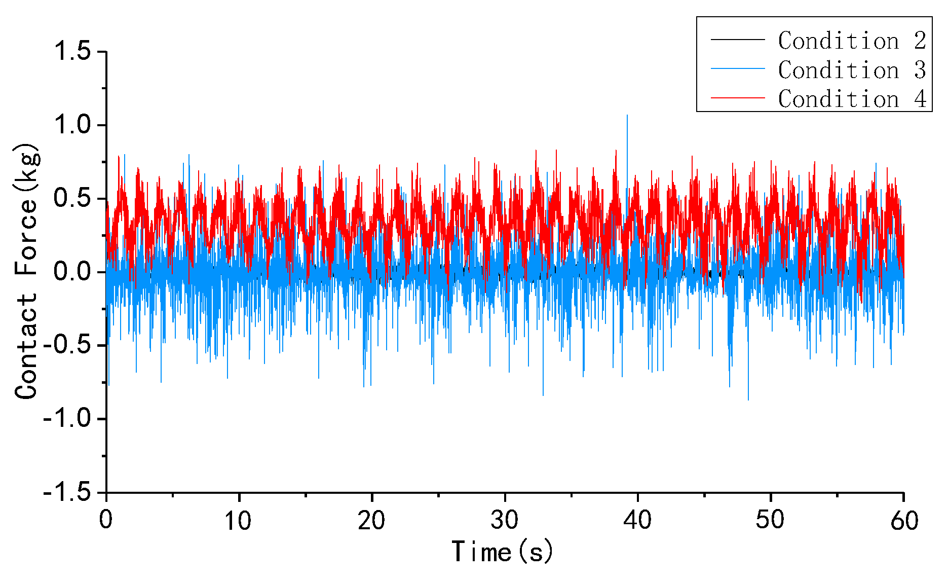
Figure 7 shows a typical plot of contact force in time history. Obviously, what can be observed is that under condition 2, the contact force is very small; under condition 3, the contact force is between ±0.7 kg; and under condition 4, the contact force is between −0.2 kg and 1.0 kg. It can be seen that under the conditions of the same draft depth and the same towing speed the contact force between the vessel and CBF increases with the increase in wave height. It can also be seen from the figure that the contact force shows that the tensile force increases with the increase in wave height. The time history diagram shows that the maximum tension is no more than 1 kg, that is to say, if more than 1 kg pre-tension is provided, the vessel and CBF will not separate.

3.4. Effect of Speed

Taking the towing speed as the main variable, and keeping other factors unchanged, we can obtain the following conditions (Table 6); the values in the table are the model-scale values.
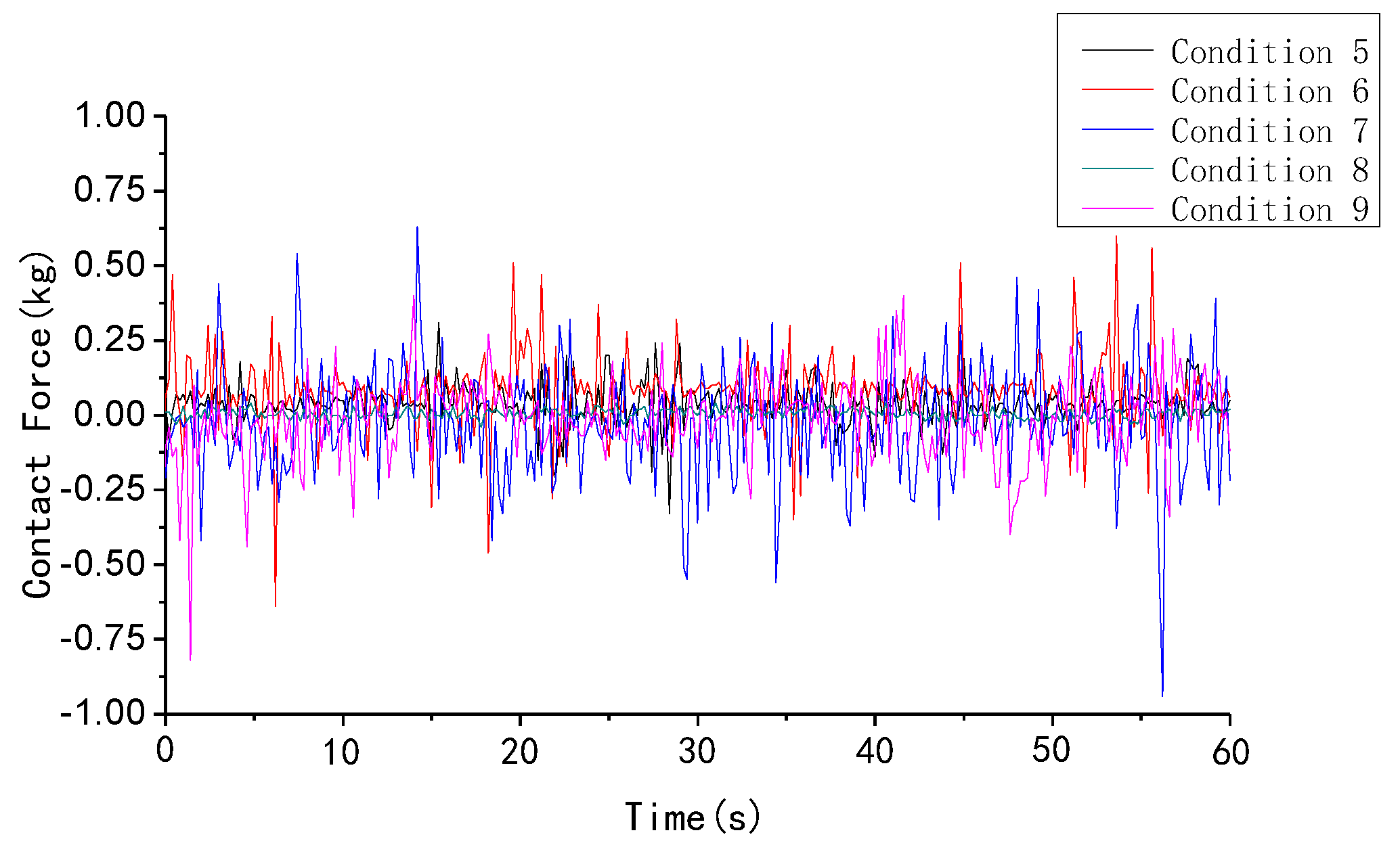
The analysis conditions are shown in Table 6. Figure 8 shows a typical plot of contact force in time history. It is clear from Figure 8 that, given the constant draft depth and wave height, the contact force between the vessel and CBF increases with the increase in the towing speed. The value of the contact force is between ±1 kg. As the towing speed increases, the contact force between the vessel and the CBF shows little fluctuation. When the traction speed increases from 0.22 m/s to 0.50 m/s, the contact force between the vessel and CBF increases from 0.1 kg to 0.7 kg. This indicates that when we select an appropriate draft and wave condition, the influence of speed on contact force is relatively small. This also means that in practical projects, when the wave conditions meet the standard, we can shorten the overall towing time by increasing the towing speed, which will not greatly affect the overall towing safety.

3.5. Effect of Draft Depth

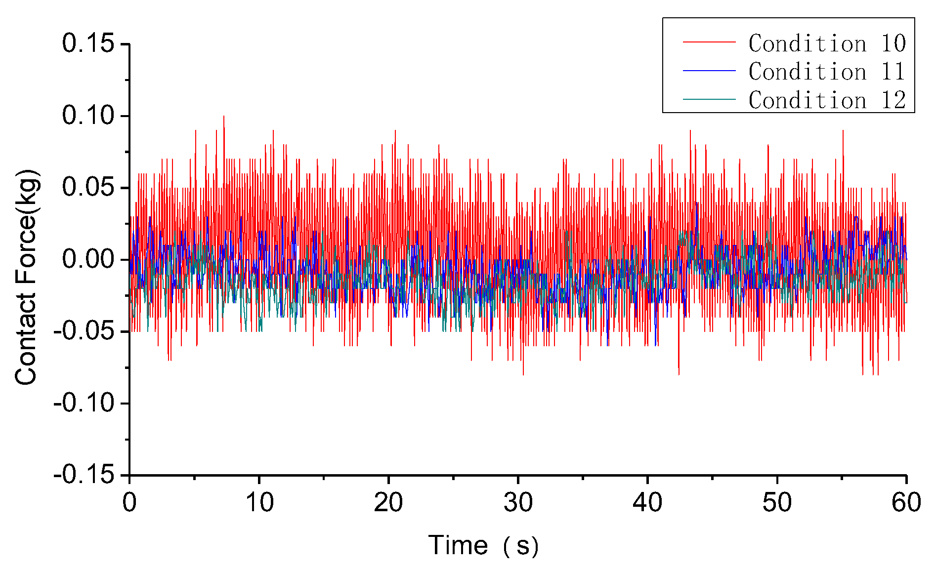
Taking the draft depth as the main variable, and keeping other factors unchanged, we can obtain the following conditions (Table 7); the values in the table are the model-scale values.
Figure 9 shows a typical plot of contact force in time history. At first glance, it can be seen that the instantaneous value of contact force is between ±0.1 kg, which is quite small. In addition, the contact force between the vessel and the CBF decreases as the draft increases. The fluctuation of contact force between the vessel and CBF also decreases with the increase in draft.

4. Experimental Results and Practical Engineering Verification

It can be seen from the experimental data that the maximum contact force during towing is close to 2 kg. This means that providing a pre-tension of 2 kg can ensure that the CBF and vessel will not separate during the towing process. According to the 1:50 similarity ratio, it can be restored to the project. By setting a reasonable safety factor, the pre-tension of 500 t can be set in the actual project.
Taking a practical project as an example, we monitored the contact force between the vessel and CBF during the towing process.
Figure 10 shows that in the process of towing, there is still a contact force of at least 490 t between the vessel and CBF, and the bonding between the vessel and CBF is tight enough. The one-step installation method of composite bucket foundation can meet the requirements of the vessel and CBF and does not detach during towing. When towing with another composite bucket foundation, according to previous towing experience, a 500 t contact force is still adopted as the control standard. From the data collected by the sensors, it can be seen that during towing, the fluctuation of force between the vessel and CBF does not exceed 30 t. This shows the reliability of the experimental results. The floating transportation of more than 40 actual engineering CBF has been completed based on this method.

5. Conclusions

In this paper, the integrated floating transport technique of offshore CBF is introduced. The model test was also conducted to study the contact force between the vessel and the CBF. Based on the results, the following conclusions are made:
(1)
In the process of towing, the combination of the vessel and CBF is good. It meets the requirements of towing in long-distance and complex sea conditions. The contact force of the bow facing the wave is much greater than that of the stern. The contact force fluctuation of the bow facing the wave is also much larger than that of the stern.
(2)
From the model test results, it can be seen that the three factors have a certain influence on the contact force between the vessel and CBF. The contact force between the vessel and CBF increases with the increase in the towing speed. The contact force between the vessel and CBF increases with the increase in wave height. The contact force between the vessel and the CBF decreases as the draft increases. Increasing the draft is conducive to the safety of wet towing. The influence of towing speed is mainly reflected in the towing resistance. The wave height will directly affect the contact force between the vessel and CBF. Therefore, if there are big waves and adverse environment, it is necessary to avoid navigation or take adequate preventive measures.
(3)
According to the experimental results, combined with the appropriate safety factor, setting 500 t pretension can ensure that the vessel and CBF will not disengage during the towing process when applied to practical engineering.
With the popularization of one-step installation technology, there are more factors related to towing that need to be studied. For example, the study of towing resistance is one of the future research directions.

Author Contributions

Conceptualization, L.M. and H.D.; methodology, L.M.; software, L.M.; validation, L.M.; formal analysis, L.M.; investigation, L.M.; re-sources, L.M.; data curation, L.M.; writing—original draft preparation, L.M.; writing—review and editing, L.M.; visu-alization, L.M.; supervision, H.D.; project administration, H.D.; funding acquisition, H.D. All authors have read and agreed to the published version of the manuscript.

Funding

The authors would like to acknowledge the support from the National Natural Science Foundation of China (Grant Nos. 51679163 & 51779171), Innovation Method Fund of China (Grant No. 2016IM030100) and the Tianjin Municipal Natural Science Foundation (Grant No. 17JCYBJC22000).

Conflicts of Interest

The authors declare no conflict of interest.

References

  1. Energy, D.O.N.G. Suction Bucket Jacket Foundation Installed at Borkum Riffgrund 1 (Gallery). 2014. Available online: https://www.offshorewind.biz/2014/08/28/suction-bucket-jacket-foundation-installed-at-borkum-riffgrund-1-gallery/ (accessed on 15 March 2021).
  2. Esteyco. Elisa—Elican Project, World´s First Cranesless Bottom-Fixed Offshore Turbine. 5MW “Elisa” Prototype. Available online: https://www.esteyco.com/proyectos/elisa-elican-project/ (accessed on 5 June 2021).
  3. Lee, G.; Kwag, D.; Kim, S.R. Seismic Response Comparison of Offshore Wind Turbines as Types of Support Structures. J. Wind Energy 2019, 10, 5–13. [Google Scholar] [CrossRef]
  4. Smart, G.; Smith, A.; Warner, E.; Sperstad, I.B.; Prinsen, B.; Lacal-Arantegui, R. IEA Wind Task 26: Offshore Wind Farm Baseline Documentation; National Renewable Energy Lab.: Golden, CO, USA, 2016. [Google Scholar] [CrossRef] [Green Version]
  5. Lacal-Arántegui, R.; Yusta, J.M.; Domínguez-Navarro, J.A. Offshore wind installation: Analysing the evidence behind improvements in installation time. Renew. Sustain. Energy Rev. 2018, 92, 133–145. [Google Scholar] [CrossRef]
  6. Guo, Y.; Wang, H.; Lian, J. Review of integrated installation technologies for offshore wind turbines: Current progress and future development trends. Energy Convers. Manag. 2022, 255, 115319. [Google Scholar] [CrossRef]
  7. Wang, X.; Zeng, X.; Li, J. A review on recent advancements of substructures for offshore wind tur-bines. Energy Convers. Manag. 2018, 158, 103–119. [Google Scholar] [CrossRef]
  8. Saidur, R.; Islam, M.; Rahim, N.; Solangi, K. A review on global wind energy policy. Renew. Sustain. Energy Rev. 2010, 14, 1744–1762. [Google Scholar] [CrossRef]
  9. Manwell, J.; Rogers, A.; McGowan, J.; Bailey, B. An offshore wind resource assessment study for New England. Renew. Energy 2002, 27, 175–187. [Google Scholar] [CrossRef]
  10. Kaldellis, J.; Kapsali, M. Shifting towards offshore wind energy-recent activity and future development. Energy Policy 2013, 53, 136–148. [Google Scholar] [CrossRef]
  11. Kaldellis, J.; Apostolou, D.; Kapsali, M.; Kondili, E. Environmental and social footprint of offshore wind energy. Comparison with onshore counterpart. Renew. Energy 2016, 92, 543–556. [Google Scholar] [CrossRef]
  12. Cheng, M.; Zhu, Y. The state of the art of wind energy conversion systems and technologies: A review. Energy Convers. Manag. 2014, 88, 332–347. [Google Scholar] [CrossRef]
  13. Sarker, B.R.; Ibn Faiz, T. Minimizing transportation and installation costs for turbines in offshore wind farms. Renew. Energy 2017, 101, 667–679. [Google Scholar] [CrossRef]
  14. Jiang, Z. Installation of offshore wind turbines: A technical review. Renew. Sustain. Energy Rev. 2021, 139, 110576. [Google Scholar] [CrossRef]
  15. Si, Y.; Chen, Z.; Zeng, W.; Sun, J.; Zhang, D.; Ma, X.; Qian, P. The influence of power-take-off control on the dynamic response and power output of combined semi-submersible floating wind turbine and point-absorber wave energy converters. Ocean Eng. 2021, 227, 108835. [Google Scholar] [CrossRef]
  16. Achmus, M.; Schroeder, C. Installation and bearing behaviour of bucket foundations for offshore structures. Bautechnik 2014, 91, 597–608. [Google Scholar] [CrossRef]
  17. Penner, N.; Grießmann, T.; Rolfes, R. Monitoring of suction bucket jackets for offshore wind turbines: Dynamic load bearing behaviour and modelling. Mar. Struct. 2020, 72, 102745. [Google Scholar] [CrossRef]
  18. Plodpradit, P.; Kwon, O.; Dinh, V.N.; Murphy, J.; Kim, K.-D. Suction Bucket Pile–Soil–Structure Interactions of Offshore Wind Turbine Jacket Foundations Using Coupled Dynamic Analysis. J. Mar. Sci. Eng. 2020, 8, 416. [Google Scholar] [CrossRef]
  19. Liu, R.; Ma, W.-G.; Qi, Y.; Wu, X.-L. Experimental studies on the drag reduction effect of bucket foundation installation under suction pressure in sand. Ships Offshore Struct. 2019, 14, 421–431. [Google Scholar] [CrossRef]
  20. Spain: Elisa Turbine Fully Installed, Awaiting Grid Connection. 2021. Available online: https://www.offshorewind.biz/2018/07/04/spain-elisa-turbine-fully-installed-awaiting-grid-connection/ (accessed on 22 June 2021).
  21. SPT Offshore. AOWF Suction Bucket Tests Jackets. 2016. Available online: https://www.sptoffshore.com/projects/aowf-suction-bucket-tests-jackets-with-suction-pile-foundations/ (accessed on 21 March 2021).
  22. Dong, X.; Lian, J.; Wang, H.; Yu, T.; Zhao, Y. Structural vibration monitoring and operational modal analysis of offshore wind turbine structure. Ocean Eng. 2018, 150, 280–297. [Google Scholar] [CrossRef]
  23. Borg, M.; Shires, A.; Collu, M. Offshore floating vertical axis wind turbines, dynamics modelling state of the art. Part I: Aerodynamics. Renew. Sustain. Energy Rev. 2014, 39, 1214–1225. [Google Scholar] [CrossRef] [Green Version]
  24. Zhang, P.; Ding, H.; Le, C. Model tests on tilt adjustment techniques for a mooring dolphin platform with three suction caisson foundations in clay. Ocean Eng. 2013, 73, 96–105. [Google Scholar] [CrossRef]
  25. Ding, H.; Lian, J.; Li, A.; Zhang, P. One-step-installation of offshore wind turbine on large-scale bucket-top-bearing bucket foundation. Trans. Tianjin Univ. 2013, 19, 188–194. [Google Scholar] [CrossRef]
  26. Zhang, P.; Han, Y.; Ding, H.; Zhang, S. Field experiments on wet tows of an integrated transportation and installation vessel with two bucket foundations for offshore wind turbines. Ocean Eng. 2015, 108, 769–777. [Google Scholar] [CrossRef]
  27. Zhang, P.; Ding, H.; Le, C. Hydrodynamic motion of a large prestressed concrete bucket foundation for offshore wind turbines. J. Renew. Sustain. Energy 2013, 5, 63126. [Google Scholar] [CrossRef]
  28. Ding, H.; Zhao, X.; Le, C.; Zhang, P.; Min, Q. Towing Motion Characteristics of Composite Bucket Foundation for Offshore Wind Turbines. Energies 2019, 12, 3767. [Google Scholar] [CrossRef] [Green Version]
  29. Ding, H.; Feng, Z.; Zhang, P.; Le, C.; Guo, Y. Floating Performance of a Composite Bucket Foundation with an Offshore Wind Tower during Transportation. Energies 2020, 13, 882. [Google Scholar] [CrossRef] [Green Version]
  30. Cardoso, J.; Vieira, M.; Henriques, E.; Reis, L. Computational analysis of the transportation phase of an innovative foundation for offshore wind turbine. Ships Offshore Struct. 2020, 16, 725–734. [Google Scholar] [CrossRef]
  31. Lian, J.; Jiang, J.; Dong, X.; Wang, H.; Zhou, H. One damping estimation approach of the parked offshore wind turbine supported by wide-shallow bucket foundation. Ocean Eng. 2021, 235, 109387. [Google Scholar] [CrossRef]
  32. Lian, J.; Wang, P.; Wang, H.; Guo, Y.; Xu, Y.; Ye, F.; Yang, Y. Experimental study of one-step overall transportation of composite bucket foundation for offshore wind turbine under the coupled dynamic action of wave and current. J. Renew. Sustain. Energy 2021, 13, 035701. [Google Scholar] [CrossRef]
  33. Castro-Santos, L.; Vizoso, A.F.; Lamas-Galdo, I.; Couce, L.C. Methodology to calculate the installation costs of offshore wind farms located in deep waters. J. Clean. Prod. 2018, 170, 1124–1135. [Google Scholar] [CrossRef]
  34. Zhang, P.; Ding, H.; Le, C. Motion analysis on integrated transportation technique for off-shore wind turbines. J. Renew. Sustain. Energy 2013, 9, 053117. [Google Scholar] [CrossRef]
  35. Ding, H.; Han, Y.; Le, C.; Zhang, P. Dynamic analysis of a floating wind turbine in wet tows based on multi-body dynamics. J. Renew. Sustain. Energy 2017, 9, 03301. [Google Scholar] [CrossRef]
Figure 1. Wind power overview. (a) New global wind installations (GW) (GWEC-Global-Wind-Report-2021) * Source: GWEC Market Intelligence; IEA World Energy Outlook (2020), volume in 2022–2024 and 2026–2029 are estimates; (b) global final energy consumption (GWEC-Global-Wind-Report-2021).
Energies 15 07970 g001
Figure 2. (a) Onshore integral construction (b) offshore one-step installation.
Energies 15 07970 g002
Figure 3. One step installation example of the composite bucket foundation. (a) Xiangshui wind farm (3.5 MW); (b) Dafeng wind farm (6.45 MW); and (c) Rudong wind farm (4 MW).
Energies 15 07970 g003
Figure 4. The vessel and the CBF model: (a) Installation of CBF; (b) Towing of CBF; (c) CBF model; and (d) 7 cabins of CBF.
Energies 15 07970 g004
Figure 5. Sensor arrangement: (a) sensor installation on CBF; (b) sensor position on CBF.
Energies 15 07970 g005
Figure 6. The contact force between vessel and CBF model.
Energies 15 07970 g006
Figure 7. The curve of contact force vs. time considering wave height effect.
Energies 15 07970 g007
Figure 8. The curve of contact force vs. time considering towing speed effect.
Energies 15 07970 g008
Figure 9. The curve of contact force vs. time considering the draft depth effect.
Energies 15 07970 g009
Figure 10. The curve of contact force during towing.
Energies 15 07970 g010
Table 1. Parameters of the vessel.
Full ScaleModel Scale
Length (m)103.22.064
Width (m)51.61.032
Depth (m)90.18
Draft of vessel (m)60.12
Displacement (t)16,7000.1336
Bottom area (m2)27831.11
Table 2. Parameters of the CBF.
Full ScaleModel Scale
Diameter (m)350.7
Depth (m)11.50.23
Weight (kg)3807 × 10330.5
Bottom area (m2)9620.385
Table 3. Wet-towing conditions used in the test.
ItemsUnitsParameter 1Parameter 2Parameter 3Parameter 4Parameter 5
Wave height H (period)m00.03 (0.86)0.05 (1.06)
Towing speed Vm/s0.220.290.360.430.50
Draft depth h1m0.120.100.08
Table 4. Wet-towing conditions used in the test.
ItemsUnitsCondition 1
Wave height H
H (period)
m0.05 (1.06)
Towing speed Vm/s0.43
Draft depth h1m0.12
Table 5. Wet-towing conditions (wave height as main variable).
ItemsUnitsCondition 2Condition 3Condition 4
Wave height H
H (period)
m00.03 (0.86)0.05 (1.06)
Towing speed Vm/s0.360.360.36
Draft depth h1m0.120.120.12
Table 6. Wet-towing conditions (speed as main variable).
ItemsUnitsCondition 5Condition 6Condition 7Condition 8Condition 9
Wave height H
H (period)
m0.03 (0.86)0.03 (0.86)0.03 (0.86)0.03 (0.86)0.03 (0.86)
Towing speed Vm/s0.220.290.360.430.50
Draft depth h1m0.120.120.120.120.12
Table 7. Wet-towing conditions (draft depth as main variable).
ItemsUnitsCondition 10Condition 11Condition 12
Wave height Hm0.030.030.03
Towing speed Vm/s0.360.360.36
Draft depth h1m0.080.100.12
Publisher’s Note: MDPI stays neutral with regard to jurisdictional claims in published maps and institutional affiliations.