Abstract
The proposed anthraquinone-bromate cell combines the advantages of anthraquinone-bromine redox flow batteries and novel hybrid hydrogen-bromate flow batteries. The anthraquinone-2,7-disulfonic acid is of interest as a promising organic negolyte due its high solubility, rapid kinetics of electrode reactions and suitable redox potentials combined with a high chemical stability during redox reactions. Lithium or sodium bromates as posolytes provide an anomalously high discharge current density of order ~A cm−2 due to a novel autocatalytic mechanism. Combining these two systems, we developed a single cell of novel anthraquinone-bromate flow battery, which showed a power density of 1.08 W cm−2, energy density of 16.1 W h L−1 and energy efficiency of 72% after 10 charge–discharge cycles.
1. Introduction
New organic electrolytes offer great possibilities for reaching high-energy densities and controlling other properties [1,2]. Due to high solubility, fast kinetics of electrode reactions and suitable redox potentials, various anthraquinone sulfo-derivatives outperform other organic redox couples. Anthraquinone-2,7-disulfonic acid (2,7-AQDS or further by default AQDS) appears to be especially fitting because, in addition to the aforementioned pros, it has a high chemical stability during redox reactions [1,2]. In 2014, an anthraquinone-bromine RFB (ABRFB) was presented. It used a sulfuric acid solution of AQDS as a negolyte and a HBr/Br2 aqueous solution as a posolyte [3]. This battery demonstrated a power density of 0.6 W cm−2 and a relatively high-capacity retention of 99.2% at a current density of 200 mA cm−2, which showed a possibility for the practical application of ABRFB. This concept has been intensively developing in further works. The power has been increased to 1 W cm−2, while an optimized condition of cycling tests allows the achievement of 88% energy efficiency values [4]. Many other studies discussed the prospects for using various AQDS isomers as RFB electrolytes in combination with other redox couples besides Br2/Br− [5,6,7,8,9,10,11].
This works represents the development of the anthraquinone-bromine RFB concept by switching to anthraquinone-bromate systems (AQBRFB). They combine the advantages of two promising flow battery concepts: the hydrogen-bromate hybrid flow system and anthraquinone-bromine RFB. Here at the posolyte side, one switches from pure bromine electroreduction to autocatalytic bromate reduction via the so-called EC” mechanism, thus dramatically enhancing the capacity of the posolyte [12,13]. Since in the EC” process the concentration of molecular bromine remains non-zero only near the cathode surface, the negative effects associated with the bromine crossover and possible side reactions are also minimized, thus enhancing the coulombic and energy efficiency of the AQBRFB compared to the common ABRFB. Vice versa, at the negolyte side, switching from H2/H+ to an AQDS/AQDSH+ negolyte redox couple, one can forego the high-cost catalyst at the anode surface without suppression of AQDS redox kinetics, which remain fast even on a porous carbon electrode.
In AQBRFB, at the cathode and in the near-cathode space, the same reactions as in the hydrogen-bromate hybrid flow system occur [12,14]:
3H2 → 6H+ + 6e− (at the cathode)
BrO3− + 6H+ → Br− + 3H2O − 6e−, E0 = 1.41 V vs. SHE (near cathode space)
As a result of the cyclic repetition of Equation (2), the bromate anion is converted into bromine, and the latter accumulates in the bulk solution and turns into the bromide anion, which repeatedly participates in Equation (1), and thereby locks the electrochemical cycle.
At the anode, the AQDS reduction/oxidation reaction, written in Equation (3), undergoes:
AQDS + 2e− + 2H+ ↔ AQDSH2, E0 = 0.22 V vs. SHE.
Therefore, the overall net reaction is:
AQDS + BrO3− ↔ AQDSH2 + Br−, E0 = 1.19 V vs. SHE.
The maximum concentration of AQDS in sulfuric solutions does not exceed 1.64 M; therefore, considering a two-electron redox process, the specific capacity reaches 89 A h L−1 for the negolyte side of the system [11]. The posolyte half-cell, due to 6-electron transition (see Equation (2)) and a good solubility of both bromates and their reaction products, corresponds to the specific capacity up to 1400 A h L−1 [15,16].
Other advantages of using a bromate oxidizing agent include its low toxicity, chemical stability at moderate acidic pH, utilization of commodity chemicals for its preparation, low cost of energy storage due to inexpensive reagents and absence of expensive catalysts, low self-discharge currents on the electrode and absence of fire and explosion hazards.
In addition to lithium bromate, it seems very promising to use commercially available sodium bromate, which has a water solubility up to 2 mol L−1 [12].
With the significant difference of charge densities in mind, one performs only the first step of the EC’’ mechanism reduction of bromate anion to a mixture of bromine-containing intermediates with the average oxidation state of Br atoms varying from +5 to +3 maximum. That ensures that redox reactions can proceed without significant overpotential even in an acidic environment and on the surface of carbon paper electrodes during cycling charge–discharge tests [17].
2. Materials and Methods
A bromine-containing posolyte 1 M LiBrO3 solution (LLC “ProfSnab”, Saint-Petersburg, Russia) and AQDS-based negolyte (LLC “Himreaktiv”, Moscow, Russia) were both used in supporting the electrolyte of H2SO4 (LLC “Himreaktiv”, Moscow, Russia) in various concentrations (3 M or 6 M for negolyte half-cell and 1 M for posolyte half-cell). Lithium bromate was used as it was. The AQDS-based negolyte was charged in a separate MEA with H2 until the AQDS was completely reduced to 0.8 M AQDSH2 to use the latter in experiments. Nafion 211 (Chemours Company, Wilmington, DE, USA), Nafion 117 (Chemours company, USA) and GP-IEM-103 (Liaoning Grepalofu NewEnergy Co., Ltd., Panjin, China) membranes were used for the experiments.
The design of the AQBRFB cell is shown below in Figure 1. The number 1 denotes titanium end plates; 2—sealing gaskets made of Viton fluororubber (DuPont, Wilmington, DE, USA); 3, 5 and 6—layers of pressed graphite foil with 3D flow fields, (Unikhimtek, Klimovsk, Russia); 4—copper foil current collectors (Grandmetal, Moscow, Russia); 7—Sigracet SGL carbon paper electrodes 39AA (SGL Carbon, Wiesbaden, Germany) in Viton fluororubber; and 8—proton exchange membrane. The flow fields in graphite foil sheets are formed according to the process described in [18].
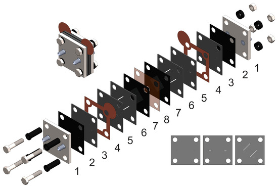
Figure 1.
The design of anthraquinone-bromate cell: 1—end plates (titanium); 2—sealing gasket (fluororubber Viton); 3,5,6—GF plates with formed flow field; 4—current collectors (copper foil); 7—sealing gasket with electrodes (carbon paper Sigracet SGL39AA); 8—proton-exchange membrane (Nafion 117, Nafion 211 or GP-IEM-103) Inset on the left—assembled view, inset on the right—layers of pressed graphite foil, which, when superimposed on each other, create a three-dimensional flow through field.
A flow-through-type field was chosen both for anodic and cathodic half-cells of the anthraquinone-bromate battery with a maximum electrolyte supply rate up to 100 mL min−1. It was also shown that an increase in negolyte viscosity at intermediate states of charge (SOC), associated with the formation of a quinhydrone complex, does not have a critical effect on the performance of the redox flow battery for this design of the anode half-cell [18,19,20]. Nafion 211 (Chemours company, USA), Nafion 117 (Chemours company, USA) and GP-IEM-103 (Liaoning Grepalofu NewEnergy Co., Ltd., China) membranes were used for the experiments.
The polarization curve for AQBRFB was obtained using a linear sweep voltammetry method with potentiostat Elins P-45X-FRA-24M (LLC Elins, Chernogolovka, Russia) in the limits from open-circuit voltage to 0 V (short-circuit current) at a scan rate of 10 mV s−1.
The internal resistance of the cell was determined via the electrochemical impedance spectroscopy method with Elins P-45X-FRA-24M (LLC Elins, Chernogolovka, Russia) in the range of 0.1 kHz–100 kHz with 20 mV amplitude.
Originally designed plates equipped with thermoresistors (GBR-618-24-20-2, Telpod, Skawina, Poland) and heat controllers were used to measure the polarization curve at an elevated temperature. Heat controllers were calibrated with thermocouple by pumping distilled water through the cell and controlling the temperature in the electrolyte reservoir. The measurement of the polarization curve at an elevated temperature was performed by the same experimental procedure at 50 °C.
Charge–discharge tests were performed at an elevated temperature in the voltage range of 0.6–1.6 V at a current density of 50 mA cm−2 to obtain values of electrolyte utilization and coulombic, voltaic and energy efficiencies (CE, VE and EE, respectively).
3. Results
Figure 2 shows the polarization curve and corresponding power density of an AQBRFB at SOC of 100%. In the first experiment, a GP-IEM-103 membrane was used, posolyte was 10 mL of 1 M LiBrO3 in 6 M H2SO4 and negolyte was 10 mL of 0.8 M AQDSH2 in 1 M H2SO4. The internal resistance of such a cell, evaluated by electrochemical impedance spectroscopy, was 0.44 Ohm cm2.
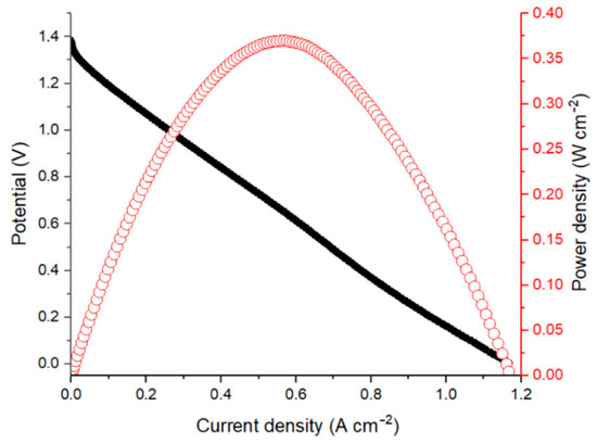
Figure 2.
Polarization curve (black dots) and corresponding power density (red dots) for an AQBRFB measured at SOC: 100%, membrane: GP-IEM-103, temperature: 25 °C, flow: through flow field, flow rate: 100 mL min−1. Posolyte composition: 1 M LiBrO3 in 6 M H2SO4, negolyte composition: 0.8 M AQDSH2 in 1 M H2SO4.
The polarization curve has a short activation losses region for current densities lower than 10 mA cm−2. However, most of the dependence represents the ohmically-dominated linear behavior. The maximum discharge power of the AQBRFB was 0.37 W cm−2 at a current density of 2 A cm−2.
Since the polarization behavior in Figure 2 was controlled by ohmic losses, to explore the maximum peak power density for AQBRFB, the GP-IEM-103 membrane (75 µm thickness) was replaced with a thinner Nafion 211 membrane (25 µm thickness), and polarization curve measurement was performed at an elevated temperature. All other experimental conditions (composition of posolyte and negolyte, type of flow field, electrolyte flow rate) remained unchanged. As a result, an internal resistance of cell reduced to 0.19 Ohm cm2, giving a total decrease of around 230% in comparison with internal resistance of the initial cell. Nevertheless, power density is determined more by discharge resistance rather than by an internal one, while discharge resistance is the sum of various contributions, including not only the internal resistance of cell but also charge-transfer resistances [21].
Discharge resistance can be obtained from the slope of a linear part of the polarization curve. In the case of the GP-IEM-103 cell, it was 1.15 Ohm cm2, decreasing to 0.28 Ohm cm2 for Nafion 211, giving a difference of more than 400%. At the same time, there are other differences between Figure 2 and Figure 3: a replacement of the GP-IEM-103 membrane by Nafion 211 and an increase in operating temperature leds to a decrease in OCV, and with decreased contribution of ohmic voltage losses, the role of activation losses became more pronounced. Taken all together, these opposing factors resulted in an increase in power density of up to 1.08 W cm−2 or more than 290%.
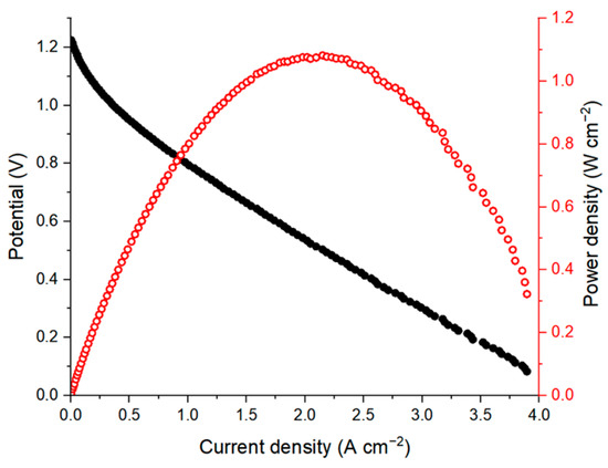
Figure 3.
Polarization curve (black dots) and corresponding power density (red dots) for an AQBRFB. SOC: 100%, membrane: Nafion-211, temperature: 50 °C, flow: through flow field, flow rate: 100 mL min−1. Posolyte composition: 1 M LiBrO3 in 6 M H2SO4, negolyte composition: 0.8 M AQDSH2 in 1 M H2SO4.
As far as we know, this is the highest peak power density for MEA using AQDS aqueous solutions as a negolyte among the published data. The previous record belongs to the conventional AQDS-bromine cell with a power density of 1 W cm−2 [4]. The proposed AQBRFB cell differs in many parameters: membrane material (Nafion 211 vs. Nafion 212 for the AQBRFB and the AQDS-bromine cells, respectively), operation temperature (50 °C vs. 40 °C), flow rate (100 mL min−1 vs. 400 mL min−1), negolyte composition (0.8 M AQDS in 1 M H2SO4 vs. 1.0 M AQDS in 1 M H2SO4) and posolyte composition (1 M LiBrO3 in 6 M H2SO4 vs. 3 M HBr/0.5 M Br). These parameters affect the power density in different ways—some of them increase the power density while others lead to a decrease. Comprehensive comparison of power densities is a very complicated task, which requires many additional experiments and lies beyond the scope of this work. Nevertheless, the value of 1.08 W cm−2 indicates a fundamental possibility of obtaining high power density systems using the anthraquinone-bromate approach.
Moreover, Figure 3 shows the significant contribution of activation voltage losses. It is widely known that both the redox kinetics and redox stability of anthraquinone derivatives could be improved by various procedures of electrode surface activation [22,23]. Thus, power density can be further improved by modification of the electrodes.
Figure 4 presents a Nyquist plot for AQBRFB at SOC 100%, demonstrating the typical dependence for RFB, which represents series-connected resistors, responsible for the cell internal resistance, RC-circuit and Warburg element [24]. An intersection of the Nyquist plot and x axis (real part of impedance) in the high-frequency range provides a reliable estimation of internal resistance, which decreases upon the charging process of RFB.
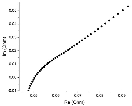
Figure 4.
Nyquist plot for an AQBRFB measured at SOC: 100%, membrane: GP-IEM-103, temperature: 25 °C, flow: through flow field, flow rate: 100 mL min−1. Posolyte composition: 1 M LiBrO3 in 6 M H2SO4, negolyte composition: 0.8 M AQDSH2 in 1 M H2SO4.
Finally, charge–discharge cycling tests of the anthraquinone-bromate system were performed in a cell with a Nafion 117 at room temperature to evaluate the main characteristics of the battery. The charge–discharge tests were carried out in a galvanostatic mode at 50 mA cm−2 current density and a voltage range of 0.6–1.6 V. A negolyte with a composition of 10 mL of 0.8 M AQDSH2 in 1 M H2SO4 and a posolyte of 10 mL of 1.0 M LiBrO3 in 3 M H2SO4 were used for further experiments. The H2SO4 concentration in the posolyte was decreased twice to ensure the balance in the ion strengths of the half-cells solutions and compensate possible osmotic imbalance. Nevertheless, the positive half-cell in the acidic supporting electrolyte had an excess capacity determined by multi-electron transition in LiBrO3. Therefore, the total capacity of the posolyte remained three times higher than in the negolyte, since each bromate molecule can be reduced with six-electron transition and the AQDSH2 molecule can only be oxidized by releasing two electrons [13].
Figure 5 shows the charge–discharge curves obtained in the second cycle. The voltage curve vs. the capacity during the charging process shows a stepwise growth in the region of 0.07 A h, which is common for similar dependences of the bromine–water system equilibrium potential predicted earlier for the electrooxidation of the bromide anion to the bromate anion [25]. The discharge capacity of the AQBRFB was 0.29 A h, which corresponds to 67% of the theoretically available 0.43 Ah. Finally, the specific capacity of AQBRFB in terms of electrolyte volume was 14.5 A h L−1, and the specific energy density was 16.1 Wh L−1 [26].
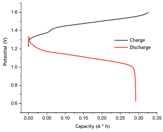
Figure 5.
Charge–discharge curves for the second cycle of AQBRFB. Cycling conditions: 50 mA cm−2 in the voltage range 0.6–1.6 V, flow rate of 100 mL min−1. Membrane: Nafion-211, temperature: 50 °C, flow: through flow field, flow rate: 100 mL min−1. Posolyte composition: 1 M LiBrO3 in 6 M H2SO4, negolyte composition: 0.8 M AQDSH2 in 1 M H2SO4.
Figure 6 shows the values of coulombic, voltaic and energy efficiencies for each cycle, which remain almost unchanged over ten charge–discharge cycles. The values of CE, VE and EE were about 85%, 83% and 72%, respectively. This in line with the level of different RFBs that use AQDS or other anthraquinone derivatives as organic electrolytes [26].
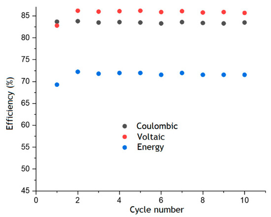
Figure 6.
Faraday, voltaic and energy efficiency of AQBRFB estimated from the results of cyclic charge–discharge tests. Cycling conditions: 50 mA cm−2 in the voltage range 0.6–1.6 V. Membrane: Nafion-211, temperature: 50 °C, flow: through flow field, flow rate: 100 mL min−1 Posolyte composition: 1 M LiBrO3 in 6 M H2SO4, negolyte composition: 0.8 M AQDSH2 in 1 M H2SO4.
Summarizing, it was shown that the AQDS—bromate approach could provide quite a promising set of main RFB characteristics—namely, power density up to 1 W cm−2, energy efficiency of about 70% and specific energy density of around 16 W h L−1. Most of them may be further improved. For instance, a separate energy density of bromate posolyte can reach values up to 810 W h kg−1 (1460 W h L−1) [2]. Another important factor is that both electrolytes of the proposed energy storage system are inexpensive because they can be obtained from abundant precursors: for example, for lithium bromate it is a calcium bromate and lithium hydroxide [27], while for AQDS—anthraquinone and oleum [28].
4. Conclusions
In this work we propose a new type of redox flow battery. The developed single cell of the anthraquinone-bromate flow battery demonstrated the following key characteristics: a power density of 1.08 W cm−2, an energy density of 16.1 W h L−1 and an energy efficiency that remained stable over 10 charge–discharge cycles and equaled 72%. These preliminary experimental results show that the anthraquinone-bromate concept tends to be a promising inorganic posolyte and organic negolyte couple for use in RFB systems, while its commercial attractiveness can be further improved by using a mixture of anthraquinone sulfo-derivatives instead of pure AQDS [28].
Further, we plan to scale up the AQBRFB concept to the 10 MEAs battery stack system while switching from carbon porous electrodes to dimensionally stable anodes (DSA) to enhance the energy capacity of the posolyte and perform the two-step six-electron bromate electroreduction via an EC’’ mechanism, resulting in the oxidation state of Br atoms’ transformation from +5 to −1.
Author Contributions
Conceptualization, A.A. and R.P.; methodology and validation, P.L., L.A., A.V., K.K. and M.P.; experimental analysis, D.C., D.V. and N.K. All authors have read and agreed to the published version of the manuscript.
Funding
The study was supported by the RSF grant (project No 21-73-30029).
Data Availability Statement
Not applicable.
Conflicts of Interest
The authors declare no conflict of interest.
References
- Wedege, K.; Dražević, E.; Konya, D.; Bentien, A. Organic Redox Species in Aqueous Flow Batteries: Redox Potentials, Chemical Stability and Solubility. Sci. Rep. 2016, 6, 39101. [Google Scholar] [CrossRef] [PubMed]
- Er, S.; Suh, C.; Marshak, M.P.; Aspuru-Guzik, A. Computational design of molecules for an all-quinone redox flow battery. Chem. Sci. 2015, 6, 885–893. [Google Scholar] [CrossRef] [PubMed]
- Huskinson, B.; Marshak, M.; Suh, C.; Er, S.; Gerhardt, M.; Galvin, C.J.; Chen, X.; Aspuru-Guzik, A.; Gordon, R.G.; Aziz, M.J. A metal-free organic–inorganic aqueous flow battery. Nature 2014, 505, 195–198. [Google Scholar] [CrossRef]
- Chen, Q.; Gerhardt, M.R.; Hartle, L.; Aziz, M.J. A Quinone-Bromide Flow Battery with 1 W/cm2 Power Density. J. Electrochem. Soc. 2016, 163, A5010–A5013. [Google Scholar] [CrossRef]
- Gerhardt, M.R.; Tong, L.; Gómez-Bombarelli, R.; Chen, Q.; Marshak, M.P.; Galvin, C.J.; Aspuru-Guzik, A.; Gordon, R.G.; Aziz, M.J. Anthraquinone Derivatives in Aqueous Flow Batteries. Adv. Energy Mater. 2017, 7, 1488. [Google Scholar] [CrossRef]
- Goulet, M.-A.; Tong, L.; Pollack, D.A.; Tabor, D.P.; Odom, S.A.; Aspuru-Guzik, A.; Kwan, E.E.; Gordon, R.G.; Aziz, M.J. Extending the Lifetime of Organic Flow Batteries via Redox State Management. J. Am. Chem. Soc. 2020, 141, 8014–8019. [Google Scholar] [CrossRef]
- Gao, F.; Li, X.; Zhang, Y.; Huang, C.; Zhang, W. Electrocatalytic Activity of Modified Graphite Felt in Five Anthraquinone Derivative Solutions for Redox Flow Batteries. ACS Omega 2019, 4, 13721–13732. [Google Scholar] [CrossRef]
- Tong, L.; Chen, Q.; Wong, A.A.; Gómez-Bombarelli, R.; Aspuru-Guzik, A.; Gordon, R.G.; Aziz, M.J. UV-Vis spectrophotometry of quinone flow battery electrolyte for in situ monitoring and improved electrochemical modeling of potential and quinhydrone formation. Phys. Chem. Chem. Phys. 2017, 19, 31684–31691. [Google Scholar] [CrossRef]
- Khataee, A.; Wedege, K.; Dražević, E.; Bentien, A. Differential pH as a method for increasing cell potential in organic aqueous flow batteries. J. Mater. Chem. A 2017, 5, 21875–21882. [Google Scholar] [CrossRef]
- Mazúr, P.; Charvát, J.; Mrlík, J.; Pocedič, J.; Akrman, J.; Kubáč, L.; Řeháková, B.; Kosek, J. Evaluation of Electrochemical Stability of Sulfonated Anthraquinone-Based Acidic Electrolyte for Redox Flow Battery Application. Molecules 2021, 26, 2484. [Google Scholar] [CrossRef]
- Bauer, S.; Namyslo, J.C.; Kaufmann, D.E.; Turek, T. Evaluation of Options and Limits of Aqueous All-Quinone-Based Organic Redox Flow Batteries. J. Electrochem. Soc. 2020, 167, 110522. [Google Scholar] [CrossRef]
- Tolmachev, Y.V.; Piatkivskyi, A.; Ryzhov, V.V.; Konev, D.V.; Vorotyntsev, M. Energy cycle based on a high specific energy aqueous flow battery and its potential use for fully electric vehicles and for direct solar-to-chemical energy conversion. J. Solid State Electrochem. 2015, 19, 2711–2722. [Google Scholar] [CrossRef]
- Vorotyntsev, M.A.; Antipov, A.E.; Konev, D.V. Bromate Anion Reduction: Novel Autocatalytic (EC″) Mechanism of Electrochemical Processes. Its Implication for Redox Flow Batteries of High Energy and Power Densities. Pure Appl. Chem. 2017, 89, 1429–1448. [Google Scholar] [CrossRef]
- Modestov, A.D.; Konev, D.; Tripachev, O.V.; Antipov, A.E.; Tolmachev, Y.V.; Vorotyntsev, M.A.; Oleg, T. A Hydrogen-Bromate Flow Battery for Air-Deficient Environments. Energy Technol. 2017, 6, 242–245. [Google Scholar] [CrossRef]
- Modestov, A.D.; Konev, D.V.; Antipov, A.E.; Vorotyntsev, M.A. Hydrogen-bromate flow battery: Can one reach both high bromate utilization and specific power? J. Solid State Electrochem. 2019, 23, 3075–3088. [Google Scholar] [CrossRef]
- Petrov, M.M.; Modestov, A.D.; Konev, D.V.; Antipov, A.E.; Loktionov, P.A.; Pichugov, R.D.; Kartashova, N.V.; Glazkov, A.T.; Abunaeva, L.Z.; Andreev, V.N.; et al. Redox flow batteries: Role in modern electric power industry and comparative characteristics of the main types. Russ. Chem. Rev. 2021, 90, 677–702. [Google Scholar] [CrossRef]
- Petrov, M.M.; Konev, D.V.; Antipov, A.E.; Kartashova, N.V.; Kuznetsov, V.V.; Vorotyntsev, M.A. Theoretical Analysis of Changes in the System’s Composition in the Course of Oxidative Electrolysis of Bromide Solution: pH Dependence. Russ. J. Electrochem. 2020, 56, 883–898. [Google Scholar] [CrossRef]
- Pichugov, R.D.; Konev, D.V.; Petrov, M.M.; Antipov, A.E.; Loktionov, P.A.; Abunaeva, L.Z.; Usenko, A.A.; Vorotyntsev, M.A. Electrolyte Flow Field Variation: A Cell for Testing and Optimization of Membrane Electrode Assembly for Vanadium Redox Flow Batteries. ChemPlusChem 2020, 85, 519. [Google Scholar] [CrossRef]
- Houser, J.; Pezeshki, A.; Clement, J.T.; Aaron, D.; Mench, M.M. Architecture for improved mass transport and system performance in redox flow batteries. J. Power Sources 2017, 351, 96–105. [Google Scholar] [CrossRef]
- Houser, J.; Clement, J.; Pezeshki, A.; Mench, M.M. Influence of architecture and material properties on vanadium redox flow battery performance. J. Power Sources 2016, 302, 369–377. [Google Scholar] [CrossRef]
- Gandomi, Y.A.; Aaron, D.S.; Houser, J.R.; Daugherty, M.C.; Clement, J.T.; Pezeshki, A.M.; Ertugrul, T.Y.; Moseley, D.P.; Mench, M.M. Critical Review—Experimental Diagnostics and Material Characterization Techniques Used on Redox Flow Batteries. J. Electrochem. Soc. 2018, 165, A970–A1010. [Google Scholar] [CrossRef]
- Permatasari, A.; Shin, J.W.; Lee, W.; An, J.; Kwon, Y. The effect of plasma treated carbon felt on the performance of aqueous quinone-based redox flow batteries. Int. J. Energy Res. 2021, 45, 17878–17887. [Google Scholar] [CrossRef]
- Xia, L.; Huo, W.; Zhang, H.; Xu, K.; Qing, Y.; Chu, F.; Zou, C.; Liu, H.; Tan, Z. Enhancing the Cycling Stability of Anthraquinone-Based Redox Flow Batteries by Using Thermally Oxidized Carbon Felt. ACS Appl. Energy Mater. 2022, 5, 1984–1991. [Google Scholar] [CrossRef]
- Sun, C.-N.; Delnick, F.M.; Aaron, D.S.; Papandrew, A.B.; Mench, M.M.; Zawodzinski, T.A., Jr. Probing Electrode Losses in All-Vanadium Redox Flow Batteries with Impedance Spectroscopy. ECS Electrochem. Lett. 2013, 2, A43–A45. [Google Scholar] [CrossRef]
- Petrov, M.M.; Konev, D.V.; Kuznetsov, V.V.; Antipov, A.E.; Glazkov, A.T.; Vorotyntsev, M.A. Electrochemically driven evolution of Br-containing aqueous solution composition. J. Electroanal. Chem. 2019, 836, 125–133. [Google Scholar] [CrossRef]
- Chen, Q.; Eisenach, L.; Aziz, M.J. Cycling Analysis of a Quinone-Bromide Redox Flow Battery. J. Electrochem. Soc. 2016, 163, A5057–A5063. [Google Scholar] [CrossRef]
- Konev, D.V.; Antipov, A.E.; Vorotyntsev, M.; Shindarova, J.A.; Vekshina, J.V.; Pichugov, R.D. Method for Lithium Bromate and Its Monohydrate Production. RUS Patent 2703618, 21 October 2019. [Google Scholar]
- Petrov, M.; Chikin, D.; Abunaeva, L.; Glazkov, A.; Pichugov, R.; Vinyukov, A.; Levina, I.; Motyakin, M.; Mezhuev, Y.; Konev, D.; et al. Mixture of Anthraquinone Sulfo-Derivatives as an Inexpensive Organic Flow Battery Negolyte: Optimization of Battery Cell. Membranes 2022, 12, 912. [Google Scholar] [CrossRef]


Publisher’s Note: MDPI stays neutral with regard to jurisdictional claims in published maps and institutional affiliations. |
© 2022 by the authors. Licensee MDPI, Basel, Switzerland. This article is an open access article distributed under the terms and conditions of the Creative Commons Attribution (CC BY) license (https://creativecommons.org/licenses/by/4.0/).