Abstract
Ruddlesden–Popper (RP) transition-metal oxide phases with the general formula An+1BnO3n+1 are versatile functional materials that can accommodate a large variety of compositions without compromising structural stability. Substitutions at the A and B sites allow for the precise control of functional properties of these materials. This opens wide possibilities for rational design. In particular, some of these materials were demonstrated to be efficient and stable catalysts for electrochemical oxygen evolution reaction (OER)—one of the key processes in fuel cells and water electrolyzers. In this work, RP phases LaSrM11−xM2xO4±δ (M1, M2—Fe, Co, Ni) with unreported stoichiometry are prepared from aqueous solutions of metal nitrates using the ultrasonic spray-pyrolysis (USP) technique. We found that the phase purity of samples synthesized by USP is higher as compared to samples prepared by solid-state synthesis or by precipitation from aqueous solutions followed by calcination, used in previous studies of RP oxides. LaSrFe0.5Ni0.5O4–δ (LSNF) oxides are found to be very active in OER in alkaline solutions, with overpotential 0.27 V at j = 0.1 A cm–2 of visible electrode surface in a 5 M solution of KOH. This overpotential is on par with the noble-metal-based OER electrocatalysts. Moreover, the catalytic performance of LSNF in OER is found to be stable over the electrolysis time even in the strongly alkaline solution. These two factors let us conduct the water splitting process in more concentrated electrolytes decreasing the energy cost of hydrogen production by water electrolysis.
1. Introduction
Electrolytic water splitting is a prospective method for the production of pure hydrogen. Hydrogen obtained by electrolysis does not contain carbon-containing impurities [1] causing the poisoning of catalysts and, therefore, can be used in low-temperature fuel cells as a fuel [2]. However, electrolytically generated hydrogen is considerably more expensive than hydrogen obtained by non-electrochemical methods due to high electricity consumption during electrolysis [3,4]. A theoretical cell voltage of 1.23 V is required to split water molecules at 25 °C; however, over 1.8 V is needed in practice due to activation barriers of both cathodic and anodic reactions.
Oxygen evolution reaction (OER) is a complex four electron-proton transfer process, which proceeds at relatively high overpotentials [5,6]. For this reason, effective and stable OER catalysts are needed for the efficient and competitive hydrogen production by electrolysis. Perovskites ABO3±x attract interest for energy-related applications because of their structural flexibility and stability. In alkaline media, perovskites demonstrated catalytic activity that is not inferior to the catalysts based on noble metal oxides [7,8].
It has been shown that La-based perovskites LaBO3 catalyze OER in alkaline media, reducing its overvoltage [9,10,11]. It is believed that oxygen evolution on perovskite electrodes proceeds according to the so-called lattice oxygen mechanism (LOM) [11,12,13]. In this mechanism, lattice oxygen atoms bonded with the atom of transition metal act as active centers for OER. Water reacts with lattice oxygen instead of metal sites, and oxygen vacancies are formed while O2 is generated [14]:
Olat + H2O → Vo + O2 + 2H+ + 2e
Lowering the activation energy barrier results in high catalytic activity in OER in comparison to the route through the conventional oxygen-containing adsorbates forming on the electrode surface [15,16,17].
The energy of interaction between d-metal atoms and adsorbed species should be neither too strong nor too week according to the Sabatier’s principle [12]. Density functional theory (DFT) calculations can evaluate the perspectives and limitations of OER catalysts based on LOM [18,19]. Reliable and precise data on the structure of perovskites are needed for their realization.
Despite the undoubted advantages of perovskites as OER electrocatalysts, there are some challenges that need to be solved. Mainly, they are associated with their low electrical conductivity and less active sites at the surface of perovskite electrodes [11]. Several approaches have been proposed to overcome these shortcomings. Ruddlesden–Popper (RP) phases An+1BnX3n+1 can be considered as layered derivatives of perovskites. RP phases share many similar characteristics to simple perovskites, such as rich chemical compositions and changeable oxygen stoichiometries [20]. Mixed B-site RP phases Sr2(RuxIr1–x)O4 demonstrated enhanced catalytic activity in OER in acidic media [14].
A series of catalysts La0.5Sr1.5Ni1−xFexO4±δ showed promising results for OER catalysis in alkaline solutions [21]. The authors used a chemical precipitation of hydrated oxides by tetramethylammonium hydroxide (TMAOH) to obtain catalyst samples. The sol-gel method, which allows one to obtain catalysts of homogeneous morphology with a high surface area, was also successfully used for the synthesis of perovskite catalysts in [22,23].
The synthetic route used for synthesis of perovskite-type catalysts affects their catalytic properties. Depending on the synthesis methodology and operational parameters, multifarious morphologies and particle sizes of perovskite oxides can be obtained [24]. Various techniques, namely, solid-state synthesis, the sol-gel method, and hydrothermal synthesis can be used to obtain target catalytic materials. However, these methods have some disadvantages in our particular case. Solid-state synthesis includes the obligatory step of precursors pelletizing before the final annealing in order to improve the diffusion conditions of reagents, but pressing cannot be applied since it results in a decrease in surface area of the catalyst. Syntheses based on co-precipitation of hydrated oxides are usually carried out in alkaline solutions. Under these conditions, the precipitation of strontium is not complete due to its alkaline nature. Moreover, carbon-containing impurities may contaminate the catalysts. Their oxidation during the final annealing partially reduces the crystallinity and, therefore, affects the catalytic properties of obtained compounds.
The spray-pyrolysis deposition technique was successfully used for the synthesis of perovskite-based catalysts in [25,26,27]. This method can also be used for obtaining RP phases [28]. The USP method allows for the preparation of catalysts with better homogeneity due to a superior mixing of reagents in the solution. It should be noted that ultrasonic spray-pyrolysis is a rather fast and simple tool for the catalyst synthesis.
However, the data on the effect of the synthetic route on the phase composition, morphology and electrochemical properties of La0.5Sr1.5Ni1−xFexO4±δ catalysts with RP structure are lacking in literature. In addition, increasing the variety of transition metal species can improve our understanding of these effects and uncover new pathways for improving the catalytic performance of the materials.
In this work, RP phases with unreported stoichiometry LaSrM11−xM2xO4±δ (M1, M2—Fe, Co, Ni) are prepared from aqueous solutions of metal nitrates using the ultrasonic spray-pyrolysis (USP) technique. The obtained mixed oxide powders are characterized by powder X-ray diffraction analysis (PXRD), scanning electron microscopy (SEM), high angle annular dark-field scanning transmission electron microscopy (HAADF-STEM) and energy-dispersive X-ray spectroscopy (EDX). We find that the phase purity of samples synthesized by spray pyrolysis is higher as compared to samples prepared by solid-state synthesis or by precipitation from aqueous solutions followed by calcination, used in previous studies of RP oxides. Crystal lattice parameters for RP oxides were determined using Rietveld refinement. RP oxides LaSrM11−xM2xO4±δ (M1, M2—Fe, Co, Ni) prepared by the USP technique are tested as anode materials for OER in 5.0 M KOH. Voltammetric measurements revealed that LaSrNi1−xFexO4±δ anodes are promising materials for OER in alkali solutions. With these anodes, oxygen evolution starts at 1.45 V (relative to the reversible hydrogen electrode potential), the overpotential of OER is equal to ~0.27 V at j = 0.1 A cm–2. This overpotential is lower than for previously studied RP stoichiometries. LaSrNi1−xFexO4±δ oxides also demonstrated exceptional stability of both catalytic effect towards OER and the electrode material itself during long-term potentiostatic electrolysis. Thus, our results clearly demonstrate the great prospects for designing efficient OER catalysts based on RP oxide phases.
2. Materials and Methods
2.1. Synthesis of Catalysts
All reagents used for the synthesis of catalysts were of analytical grade and used without further purification. Lanthanum nitrate La(NO3)3·6H2O (NevaReactiv, Saint Petersburg, Russia, purity ≥99.0%, ultra-pure), strontium nitrate Sr(NO3)2·4H2O (Alfa Aesar, Haverhill, MA, USA, ≥98.5%, extra pure), iron(III) nitrate Fe(NO3)3·9H2O (Alfa Aesar, USA, >98.0%, extra pure), nickel nitrate Ni(NO3)2·6H2O (Sigma Aldrich, St. Louis, MO, USA, ≥99.0%, ultra-pure), and cobalt nitrate Co(NO3)2·6H2O (Sigma Aldrich, USA, ≥99.0%, ultra-pure) were used for synthesis of RP oxides LaSrNi0.5Fe0.5O4–δ, LaSrCo0,5Fe0,5O4–δ and LaSrCo0.5Ni0.5O4–δ denoted further as LSNF, LSCF and LSCN, respectively.
At the first stage of synthesis of catalysts by the ultrasonic spray pyrolysis (USP) method, the required amount of nitrates were dissolved in deionized water (MilliQ, R > 18.2 MΩ cm, TOC < 3 ppb). Molar ratios between metal concentrations in solution were: La:Sr:Ni:Fe = 1:1:0.5:0.5 for LSNF, La:Sr:Co:Fe = 1:1:0.5:0.5 for LSCF and La:Sr:Co:Ni = 1:1:0.5:0.5 for LSCN. The total concentration of dissolved salts in solutions was equal to 15 wt.%. The prepared solutions were filtered from mechanical impurities. After that, they were ultrasonically sprayed using a household ultrasonic humidifier at ν = 2.5 MHz and transferred with an air flow (Vair flow = 150 mL s–1) into a tubular furnace preheated to 750 °C with the hot zone length of 200 mm. The centrifugal pump located after the filter created an additional thrust of flow. Atmospheric pressure (0.1 MPa) was used in the synthesis process. A schematic representation of spray pyrolysis system is shown in Scheme 1.
Scheme 1.
Spray-pyrolysis system.
Spray-pyrolysis was carried out in the air flow since the catalysts contain Ni(III) and/of Co(III) ions, and the oxidative atmosphere is highly desirable to obtain them. Moreover, oxygen releases in the course of the thermal decomposition of nitrates used for the synthesis.
The resulting powders were collected with a Schott funnel with a glassy G4 filter. Then, the powders were additionally annealed at 850 °C for 15 h in a muffle furnace. The phase purity of the synthesis product was determined by powder X-ray diffraction.
Catalyst samples of the studied compositions were also prepared by chemical precipitation (Pechini method [29]), and by a solid-state synthesis in order to compare their purity and choose the optimal synthetic route.
2.2. Powder X-ray Diffraction
A phase purity of prepared catalysts and the lattice parameters of RP oxides were determined by the powder X-ray diffraction (PXRD) technique using Bruker D8 ADVANCE diffractometer with Bragg—Brentano (reflection) geometry, energy dispersive detector LYNXEYE XE, Cu Kα1 radiation, λ = 1.54051 Å. The Rietveld refinement of the crystal structure was performed with the JANA2006 software.
2.3. Scanning Electron Microscopy
The morphology of the obtained samples was investigated with electron microscopy at Thermo Fisher Scientific Quattro S microscope equipped with secondary electrons, back scattered electron and energy-dispersive X-ray detectors. All pictures were shot at high vacuum conditions with currents in range from 87 pA to 200 nA and an accelerating voltage range of 5–30 kV.
2.4. Scanning Transmission Electron Microscopy
Preparation of catalysts for scanning transmission electron microscopy (STEM) included grinding of powders using an agate mortar and pestle in isopropyl alcohol and subsequent application of a drop of the resulting suspension to a copper grid with a carbon film. High angle annular dark-field scanning transmission electron microscopy (HAADF-STEM) images, bright field scanning transmission electron microscopy (BF-STEM) images and energy-dispersive X-ray STEM-EDX compositional maps were obtained on a probe aberration corrected FEI Titan Themis Z transmission electron microscope at 200 kV equipped with a Super-X system for EDX analysis.
2.5. Surface Area Analysis
The analysis of the specific surface area of the obtained catalysts was carried out using the Quantachrome Instruments NOVA 2000 high-speed surface area analyzer at 77 K. Immediately before the measurement, the powders were degassed under dynamic vacuum condition for 6 h at 200 °C to avoid measurement errors. The Brunauer–Emmett–Teller (BET) method was used to calculate the true surface area of samples using nitrogen adsorption data in the relative pressure range (P/P0) from 0.05 to 0.30.
2.6. Inductively Coupled Plasma Atomic Emission Spectroscopy
For the inductively coupled plasma atomic emission spectroscopy (ICP-AES) experiments, the 10 mL of 5 M KOH electrolyte after the electrochemical treatment of the LSNF sample was collected. The electrochemical polarization was performed in the galvanostatic condition at 1.5 V vs. RHE for 2 h (mass loading 100 μg·cm–2). The solution after electrolysis was analysed by ICP-AES using a Jobin-Yvon 32-38 PI VHR spectrometer (ISA Instruments, Paris, France).
2.7. Electrochemical Measurements
Electrochemical measurements were performed in a standard three-electrode cell (V = 100 mL) made from Teflon using a Metrohm Autolab PGSTAT302N bipotentiostat equipped with a linear scan generator module. A glassy carbon (GC) plate with Sgeom = 0.07 cm2 was used as a working electrode. Before experiments, the surface of glassy carbon was polished with a 0.05 μm Al2O3 slurry on a polishing cloth, ultrasonicated for 10 s, rinsed with distilled water several times, and finally dried under an N2 stream.
A glassy carbon (GC) disk electrode was used as a support to deposit RP-phase thin film. Oxide powder was deposited onto glassy carbon (GC) disk electrodes as a thin film. For this, a calculated amount of RP-phase powder was mixed with an isopropanol/water solution (1:4 by volume), which contained 0.06 wt % Na-substituted Nafion (Sigma Aldrich) to reach a weight ratio ∼1 g Nafion: 1 g catalyst. The resulted inks were sonicated for 60 min to reach a uniform solution. Two portions (2.7 and 2 μL) of the obtained ink were deposited onto the glassy carbon disk electrode using a micropipette and dried under a N2 stream. The total catalyst loading always was ca. 100 μg·cm–2.
An electrolytic cell was filled with 5 M KOH (pH = 14.69) (Sigma-Aldrich) at 25 °C. The dependence of specific conductivity of potassium hydroxide solutions on their concentration has a maximum at 0.3 wt. KOH, which approximately corresponds to 4.5 M solution. The choice of alkaline solutions is due to the fact that such solutions are used in industry. Moreover, oxide electrodes could be unstable in an acid environment [30].
The temperature of the solution was adjusted by a water-cooled thermostatic bath. A platinum wire was used as a counter electrode. Electrode potentials were set and measured against mercury-mercuric oxide (Hg/HgO) reference electrode filled with the same alkali solution. All potentials reported in the present paper were recalculated versus a reversible hydrogen electrode (RHE) via the equation:
E(RHE) = E(Hg/HgO in 5 M KOH) + 0.879 V
Before voltammetric measurements, a solution was deaerated by argon (extra pure) bubbling during 30 min. The OER kinetics was investigated both under potentiodynamic and potentiostatic conditions. Cyclic voltammograms were recorded at scan rates v = 5–100 mV s–1 starting from the open-circuit potential. In order to determine the stability of prepared catalysts long-term potentiostatic current transients were recorded at potentials of oxygen evolution.
3. Results
3.1. Crystal structure
The product of solid-state synthesis of LSNF has relatively low phase purity (Figure 1). One can see that there are not only reflexes corresponding to the RP phase, but also reflexes associated with initial reagents for synthesis—lanthanum and iron oxides in the diffractograms. The appearance of reflections not corresponding to RP phases means that not only RP phase, but also other phases are present in the sample. Therefore, the product of solid-state synthesis has low homogeneity.
Figure 1.
Diffractograms of LSNF prepared by the solid-state method, Pechini method and ultrasonic spray-pyrolysis.
Obviously, diffusion limitation of a solid-state reaction results in incomplete reaction of RP phase’s synthesis. Low rates of ion diffusion in the reagents mixture are caused by high melting points of initial oxides. As our detailed experiments have shown, the problem cannot be solved by thorough grinding of initial mixture of oxides. Therefore, solid-state synthesis is not suitable for synthesis of OER catalysts based on RP structures.
Catalysts prepared by the Pechini method have a better homogeneity as compared with solid-state synthesis (Figure 1). However, a small amount of impurity phases is also present in the final product in this case. Apparently, they are caused by the inclusion of organic precipitant molecules in hydrated oxide precipitates.
The best results were obtained using the spray-pyrolysis technique for the synthesis of RP oxides. Spraying oxides directly from the liquid phase increases the uniformity of target metals’ distribution and allows us to avoid further pelletizing at the annealing stage to obtain the purer crystalline product, which, in turn, helps to achieve a more developed surface structure. In this case, an ideal homogeneity can be achieved in solutions of nitrates used for synthesis.
As can be seen from diffractograms of all three materials (LSNF, LSCF and LSCN) prepared by the USP technique, they practically do not contain impurities (Figure 2). Lattice parameters of all synthesized mixed oxides are given in Table 1. The diffraction peaks of the USP-synthesized RP-phases coincide well with the standard XRD pattern (JCPDS #01-075-5726) and accurately point to a layered structure with a space group of I4/mmm after incorporating various transition metals. However, the exact positions of enlarged main peaks (31.7–33.1° of 2θ angle) are slightly different for LSNF, LSCF, and LSCN likely due to the difference in the ionic radii of Fe3+ (0.645 Å), Co3+ (0.615 Å) and Ni3+ (0.60 Å).
Figure 2.
Diffractograms of LSNF, LSCF and LSCN prepared by spray-pyrolysis. Annealing at 850 °C, 12 h.

Table 1.
Unit cell parameters and calculated crystalline size of the RP phases in the synthesized samples.
The PXRD pattern and further Rietveld refinement of the LSNF sample reveal 99.4% phase purity for LSNF prepared by spay-pyrolysis with unit cell parameters: a = 3.871(4) Å; b = 3.871(4) Å; c = 12.693(2) Å; V = 190.20(2) Å3. Lattice constants are obtained by the following equation for tetragonal unit cell,
Substituting the B-site of RP-phase by a metal with a larger ionic radius is increasing the cell volume correspondently. Theoretical values of crystalline size lie in the range 45–47 nm (Table 1). They were calculated using Scherrer equation:
The texture coefficient (TC) represents the texture of a particular plane, the deviation of which from unity indicates the presence of a preferred orientation of the crystal. Quantitative information about the preferred orientation of the crystal was obtained from a different texture coefficient TC (hkl), defined as the March–Dollase function, and did not reveal the presence of any defined texture in the samples (Table S3).
3.2. Morphology
Morphology of the samples prepared by USP technique demonstrates clear advantages compared with that for the samples obtained by the conventional Pechini technique. Morphologically, samples obtained by the USP method consist of porous hollow spheres with diameters varying between 150 and 1400 nm (Figure 3a). Pore diameters are in a range of 2–100 nm, and the wall thickness is ∼20 nm. The spheres are the agglomerates of primary crystalline RP structured nanoparticles mostly with an irregular shape and 15–70 nm in dimension (Figure 3b) in agreement with theoretical data prom PXRD (Table 1).
Figure 3.
(a) SEM and (b) HAADF-STEM images of LSNF sample prepared using the USP method.
In contrast, powders of RP oxides obtained by the Pechini method consist of irregular cubic shapes with face sizes varying in range from 400 to 1200 nm (Figure 4). While the spherical particles obtained by the USP method are formed directly during nitrates decomposing in the heated zone of the tubular furnace, the particles obtained by co-deposition are formed during a longer time of the sol-gel formation process.
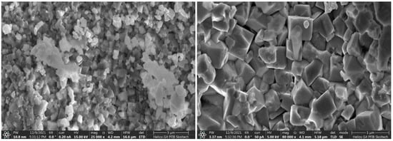
Figure 4.
SEM images of LSNF sample prepared by Pechini method.
EDX analysis revealed that the average cationic composition of La1.02Sr0.98Ni0.51Fe0.49 is in agreement with the molar ratio of nitrates of La:Sr:Ni:Fe of 1:1:0.5:0.5 taken for LSNF synthesis (Figure 5). The distribution of metal cations over the surface of particles is rather uniform (Figure S1).
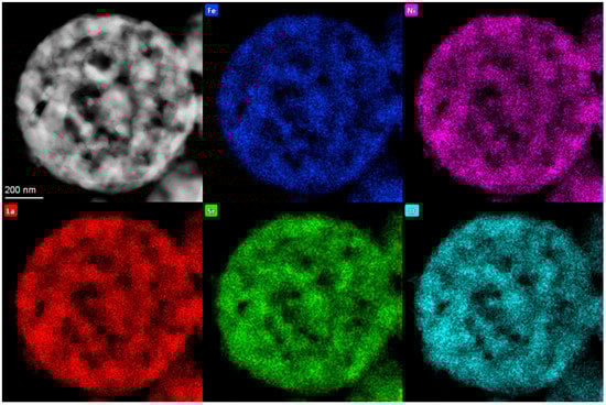
Figure 5.
HAADF–STEM image of spherical hollow particles of LSNF with STEM-EDX elements’ distribution.
3.3. Electrochemical Measurements
In alkaline solutions, OER proceeds at low overpotentials for all synthesized RP oxides (Figure 6a). The best results were obtained for LSFN oxides, on which oxygen evolution begins at a potential of ~1.45 V (RHE). This result seems promising compared with the results of OER kinetics reported for perovskites [31]. Redox transition of iron group metal ions in RP oxides occur at potentials less positive in comparison with oxygen evolution and might be described by the equation
LaSrFe0.5Ni0.5O4−δ + 2x OH− → LaSrFe0.5Ni0.5O4−δ+x + x H2O + 2x e
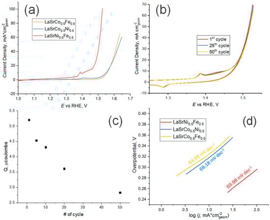
Figure 6.
(a) Cyclic voltammetry activity tests (2nd cycle) for samples prepared using the USP method on GC electrode in 5M KOH (pH 14.69) at 10 mV s–1; (b) Fifty cycles of LSNF on GC in 5M KOH at 10 mV s–1 in the range of potentials from 1 to 1.55 V (vs. RHE); (c) Integrated charge of Ni3+/Ni2+ in LSNF during 50 cycles of cyclic voltammetry at 10 mV s–1; (d) Tafel slopes for OER on samples prepared using the USP method.
The charges corresponding to these transitions have a tendency to decrease with a cycle number during a long-time cycling of the electrode potential (Figure 6b). It is probable that redox transition involves a large number of atomic layers in RP oxides. As a consequence, the rate of this reaction is rather low. Irreversible nature of iron group metal redox transition is also confirmed by the dependence of the charge corresponding to it on potential scan rate (Figure S5).
As has been shown recently, amorphization of the near-edge layer occurs during long-term anode polarization of perovskites in alkali solutions resulting in the formation of hydrated oxides of iron group metals in it, e.g., NiOOH, FeOOH, etc. [32,33,34,35] The participation of iron group metal atoms in electrochemical oxygen evolution takes place in this case too. Iron ions included in the surface layer of nickel-containing anode materials increase their activity in OER [35,36]. It is likely that due to the catalytic action of iron ions, LSFN exhibits the highest catalytic activity among the studied materials.
According to [36,37,38], oxygen evolution on perovskites in alkaline solution can be represented by the following sequence of steps:
by subsequent processes of catalytically decomposing H2O2 yielding finally O2. In this case, the theoretical Tafel slope of ~60 mV dec–1 can be expected, if we neglect the degree of surface coverage by OH species. As one can see in Figure 6d, the experimentally determined values of Tafel slopes are close to these values for LSNF, LSCF, LSCN and the oxygen evolution reaction mechanism at these samples is quite similar. However, it has to be noted that impact of the insufficient conductivity of RP-based electrocatalysts and the ensuing Ohmic drop in the catalytic layer are not easy to correct in the experimental determination of the Tafel slope.
Mz+ + OH− ⇄ M(z+1)+ − OH + e
M(z+1)+ − OH + OH− → Mz+···H2O2 + e (rate determining step)
Another important observation is the shift of the peak around 1.4 V (vs RHE) in the cyclic voltammetry measurements (Figure 6a and Figure S6). This peak is attributed to the anodic Ni(II)/Ni(III) oxidation and could be explained by the formation of a nickel oxyhydroxide layer at the surface of the samples containing Ni during electrolysis [32]. The peak for the sample containing Ni and Fe atoms at the B-site of the RP-phase shifts during electrolysis to lower potentials relative to the sample which contains Ni and Co. In the potential range from the nickel oxidation peak to OER the Fe-ions from the crystal lattice precipitate in the form of the hydroxide, or hydrated oxide is fully electrochemically oxidized to Fe3O4. Among the many compounds which can be formed during the electrochemical water splitting reaction and oxidation of Fe atoms, this ferric-ferrous oxide is the better current conductor than Co-oxides [39,40].
Long-term stability is a key requirement for any economically viable catalyst. The stability can be evaluated from potentiodynamic curves recorded in the course of long-term cycling. As one can see in Figure 6b, the differences in currents measured on the first, 25th and 50th cycles are small. This indicates a rather high stability of the prepared catalysts. This is also confirmed by long-term potentiostatic transients (Figures S3–S5). These measurements also demonstrate that the catalytic effect is stable for all studied RP oxides. Cathodic currents passing through the electrode reach a constant value after ~10 min after the start of electrolysis. No visible damage to the electrode surface was observed. In addition, the solution after electrolysis with the LSNF sample was analysed by inductively coupled plasma atomic emission spectroscopy. All concentrations of metals were at or below detection limits (c(La) < 0.15 ± 0.02 μg L–1, c(Ni) < 0.46 ± 0.02 μg L–1, c(Fe) = 5.62 ± 0.02 μg L–1, c(Sr) = 0.61 ± 0.04 μg L–1) considering the fact that commercial KOH solution contains 5 μg L–1 of iron cations.
Therefore, we can conclude that LSFN cathodes with RP structures synthesized by ultrasonic spray pyrolysis are both active and stable under electrolysis conditions in alkaline solutions. In fact, the catalytic performance of the LSNF in OER is higher than that of La0.5Sr1.5Ni1-xFexO4±δ studied previously in [21], namely, the overpotential is lower by 110 mV. This is mainly due to increasing the molar concentration of KOH in the electrolyte from 0.1 M (pH = 12.8) to 5 M (pH = 14.69) since OER’s overpotential is strongly pH-dependent. The smaller amount of Sr (1 vs. 1.5) substituted at the A-site of the RP-phases in our study increases the long-term stability of the catalysts. In addition, the greater substitution of Ni with Fe at the B-site plays a role, but studies of more different compositions are needed to quantify this effect.
4. Conclusions
Among the three tested methods (solid-state, Pechini, and USP) for the synthesis of LaSrX1−xYxO4–δ (X, Y—Fe, Co, Ni) Ruddlesden–Popper structured oxides the USP method allowed us to achieve the best homogeneity of the catalysts. Thus, our results show that USP is a better approach for the synthesis of RP oxide catalysts with well-controlled stoichiometry, which is important for a rational design of better catalysts. The RP oxide with novel stoichiometry LaSrFe0.5Ni0.5O4–δ (LSNF) is found to be the most active in OER in alkaline solutions among all RP structures LaSrM10.5M20.5O4–δ containing iron group metals. Electrochemical experiments in a 5 M solution of KOH reveal high activity of LSNF in OER with overpotential 0.27 V at j = 0.1 A cm–2 of visible electrode surface. To our best knowledge this value of overpotential is the smallest one of all previously studied perovskite-based materials. The catalytic performance was stable over the electrolysis time even in the strongly alkaline solution. These two factors let us conduct the water splitting process in more concentrated electrolytes decreasing the energy cost of hydrogen production by water electrolysis.
Supplementary Materials
The following supporting information can be downloaded at: https://www.mdpi.com/article/10.3390/en15218315/s1, Table S1: Average EDX table of element distribution in LSNF sample; Table S2: Specific surface area for samples obtained using USP method; Table S3: Texture coefficient for LSNF sample; Figure S1: SEM-EDX elements distribution in LSCN sample obtained using USP method; Figure S2: Chronoamperometry of samples obtained via USP method in OER; Figure S3: Stability tests of LSCF sample during 100 cycles in range of potentials from 1.2 to 1.58 V vs. RHE at scan rate 20 mV s−1; Figure S4: Stability tests of LSCN sample during 50 cycles in range of potentials from 1.2 to 1.6 V vs. RHE at scan rate 10 mV s−1; Figure S5: Dependence of anodic and cathodic charge for Ni redox from scan rate (5–100 mV s−1) in LSNF sample; Figure S6: Oxidation peak of Ni2+/Ni3+ at anodic cyclic voltammetry curve (2nd cycle) for LSNF and LSCF.
Author Contributions
P.A.S. synthesized, characterized, collected HAADF-STEM, SEM images, STEM EDX mapping and performed electrochemical testing. V.V.K. guided electrochemical experiments. E.A.F. collected and analyzed IPC-AES data. S.V.L. formulated the problem. P.A.S., V.V.K., S.V.L. and E.A.F. prepared the manuscript. All authors revised this manuscript. All authors have read and agreed to the published version of the manuscript.
Funding
This research was funded by the Russian Science Foundation grant number 21-13-00419.
Data Availability Statement
The data presented in this study are available on request from the corresponding author.
Acknowledgments
We thank Keith Stevenson for fruitful discussions.
Conflicts of Interest
The authors declare no conflict of interest.
References
- Lee, J.E.; Jeon, K.-J.; Show, P.L.; Lee, I.H.; Jung, S.-C.; Choi, Y.J.; Rhee, G.H.; Lin, K.-Y.A.; Park, Y.-K. Mini review on H2 production from electrochemical water splitting according to special nanostructured morphology of electrocatalysts. Fuel 2022, 308, 122048. [Google Scholar] [CrossRef]
- Zhang, J.; Zhang, Q.; Feng, X. Support and Interface Effects in Water-Splitting Electrocatalysts. Adv. Mater. 2019, 31, 1808167. [Google Scholar] [CrossRef] [PubMed]
- Ball, M.; Weeda, M. The hydrogen economy—Vision or reality? Hydrog. Use Saf. Hydrog. Econ. 2016, 4, 237–266. [Google Scholar]
- Sojoudi, A.; Sefidan, A.M.; Alam, K.C.A.; Saha, S.C. Hydrogen production via electrolysis: Mathematical modeling approach. Bioenergy Resour. Technol. 2021, 7, 199–235. [Google Scholar]
- Łuba, M.; Mikołajczyk, T.; Kuczynski, M.; Pierozynski, B.; Kowalski, I.M. Enhancing the Effectiveness of Oxygen Evolution Reaction by Electrodeposition of Transition Metal Nanoparticles on Nickel Foam Material. Catalysts 2021, 11, 468. [Google Scholar] [CrossRef]
- Alobaid, A.; Wang, C.; Adomaitis, R.A. Mechanism and Kinetics of HER and OER on NiFe LDH Films in an Alkaline Electrolyte. J. Electrochem. Soc. 2018, 165, J3395–J3404. [Google Scholar] [CrossRef]
- Hwang, J.; Rao, R.R.; Giordano, L.; Katayama, Y.; Yu, Y.; Shao-Horn, Y. Perovskites in catalysis and electrocatalysis. Science 2017, 358, 751–756. [Google Scholar] [CrossRef]
- Grimaud, A.; May, K.J.; Carlton, C.E.; Lee, Y.-L.; Risch, M.; Hong, W.T.; Zhou, J.; Shao-Horn, Y. Double perovskites as a family of highly active catalysts for oxygen evolution in alkaline solution. Natur. Commun. 2013, 4, 2439. [Google Scholar] [CrossRef]
- Hong, S.; Díez, A.M.; Adeyemi, A.N.; Sousa, J.P.S.; Salonen, L.M.; Lebedev, O.I.; Kolen’ko, Y.V.; Zaikina, J.V. Deep Eutectic Solvent Synthesis of Perovskite Electrocatalysts for Water Oxidation. ACS Appl. Mater. Interfaces 2022, 14, 23277–23284. [Google Scholar] [CrossRef]
- Bhowmick, S.; Dhankhar, A.; Sahu, T.K.; Jena, R.; Gogoi, D.; Peela, N.R.; Ardo, S.; Qureshi, M. Low Overpotential and Stable Electrocatalytic Oxygen Evolution Reaction Utilizing Doped Perovskite Oxide, La0.7Sr0.3MnO3, Modified by Cobalt Phosphate. ACS Appl. Energy Mater. 2020, 3, 1279–1285. [Google Scholar] [CrossRef]
- Liu, D.; Zhou, P.; Bai, H.; Ai, H.; Du, X.; Chen, M.; Liu, D.; Ip, W.F.; Lo, K.H.; Kwok, C.T.; et al. Development of Perovskite Oxide-Based Electrocatalysts for Oxygen Evolution Reaction. Small 2021, 17, 2101605. [Google Scholar] [CrossRef] [PubMed]
- Pan, Y.; Xu, X.; Zhong, Y.; Ge, L.; Chen, Y.; Veder, J.-P.M.; Guan, D.; O’Hayre, R.; Li, M.; Wang, G.; et al. Direct evidence of boosted oxygen evolution over perovskite by enhanced lattice oxygen participation. Natur. Commun. 2020, 11, 2002. [Google Scholar] [CrossRef] [PubMed]
- Beall, C.E.; Fabbri, E.; Schmidt, T.J. Perovskite Oxide Based Electrodes for the Oxygen Reduction and Evolution Reactions: The Underlying Mechanism. ACS Catal. 2021, 11, 3094–3114. [Google Scholar] [CrossRef]
- Wang, F.; Zhang, C.; Yang, H. Mixed B-site Ruddlesden-Popper phase Sr2(RuxIr1–x)O4 enables enhanced activity for oxygen evolution reaction. J. Energy Chem. 2022, 70, 623–629. [Google Scholar] [CrossRef]
- Zagalskaya, A.; Alexandrov, V. Role of Defects in the Interplay between Adsorbate Evolving and Lattice Oxygen Mechanisms of the Oxygen Evolution Reaction in RuO2 and IrO2. ACS Catal. 2020, 10, 3650–3657. [Google Scholar] [CrossRef]
- Wang, L.; Li, H.; Liu, J.; Lang, X.; Wang, W. Labile oxygen participant adsorbate evolving mechanism to enhance oxygen reduction in SmMn2O5 with double-coordinated crystal fields. J. Mater. Chem. 2021, A9, 380–389. [Google Scholar] [CrossRef]
- Shi, Z.; Wang, X.; Ge, J.; Liu, C.; Xing, W. Fundamental understanding of the acidic oxygen evolution reaction: Mechanism study and state-of-the-art catalysts. Nanoscale 2020, 12, 13249–13275. [Google Scholar] [CrossRef]
- Man, I.C.; Su, H.-Y.; Calle-Vallejo, F.; Hansen, H.A.; Martnez, J.I.; Inoglu, N.G.; Kitchin, J.; Jaramillo, T.F.; Nørskov, J.K.; Rossmeisl, J. Universality in Oxygen Evolution Electrocatalysis on Oxide Surfaces. ChemCatChem 2011, 3, 1159–1165. [Google Scholar] [CrossRef]
- Yoo, J.S.; Rong, X.; Liu, Y.; Kolpak, A.M. Role of Lattice Oxygen Participation in Understanding Trends in the Oxygen Evolution Reaction on Perovskites. ACS Catal. 2018, 8, 4628–4636. [Google Scholar] [CrossRef]
- Xu, X.; Pan, Y.; Zhong, Y.; Ranc, R.; Shao, Z. Ruddlesden-Popper perovskites in electrocatalysis. Mater. Horiz. 2020, 7, 2519–2565. [Google Scholar] [CrossRef]
- Forslund, R.P.; Hardin, W.G.; Rong, X.; Abakumov, A.M.; Filimonov, D.; Alexander, C.T.; Mefford, J.T.; Iyer, H.; Kolpak, A.M.; Johnston, K.P.; et al. Exceptional electrocatalytic oxygen evolution via tunable charge transfer interactions in La0.5Sr1.5Ni1–xFexO4±δ Ruddlesden-Popper oxides. Natur. Commun. 2018, 9, 3150. [Google Scholar] [CrossRef] [PubMed]
- Hardin, W.G.; Mefford, J.T.; Slanac, D.A.; Patel, B.B.; Wang, X.; Dai, S.; Zhao, X.; Ruoff, R.S.; Johnston, K.P.; Stevenson, K.J. Tuning the Electrocatalytic Activity of Perovskites through Active Site Variation and Support Interactions. Chem. Mater. 2014, 26, 3368–3376. [Google Scholar] [CrossRef]
- Omari, E.; Omari, M. Enhancing catalytic activity of NdFeO3 perovskite by tuning A-site cation deficiency for oxygen evolution reaction. Int. J. Hydrogen Energy 2022, 47, 14542–14551. [Google Scholar] [CrossRef]
- Zhang, M.; Jeerh, G.; Zou, P.; Lan, R.; Wang, M.; Wang, H.; Tao, S. Recent development of perovskite oxide-based electrocatalysts and their applications in low to intermediate temperature electrochemical devices. Mater. Today 2021, 49, 351–377. [Google Scholar] [CrossRef]
- Kuai, L.; Kan, E.; Cao, W.; Huttula, M.; Ollikkala, S.; Ahopelto, T.; Honkanen, A.-P.; Huotari, S.; Wenhai, W.; Geng, B. Mesoporous LaMnO3+δ perovskite from spray–pyrolysis with superior performance for oxygen reduction reaction and Zn–air battery. NanoEnergy 2017, 43, 81–90. [Google Scholar] [CrossRef]
- Dervishogullari, D.; Sharpe, C.A.; Sharpe, L.R. LaFexCo(1–x)O3 Thin-Film Oxygen Reduction Catalysts Prepared Using Spray Pyrolysis without Conductive Additives. ACS Omega 2017, 2, 7695–7701. [Google Scholar] [CrossRef]
- Aegerter, D.; Borlaf, M.; Fabbri, E.; Clark, A.H.; Nachtegaal, M.; Graule, T.; Schmidt, T.J. Tuning the Co Oxidation State in Ba0.5Sr0.5Co0.8Fe0.2O3–δ by Flame Spray Synthesis Towards High Oxygen Evolution Reaction Activity. Catalysts 2020, 10, 984. [Google Scholar] [CrossRef]
- Ryll, T.; Reibisch, P.; Schlagenhauf, L.; Bieberle-Huetter, A.; Döbeli, M.; Rupp, J.L.M.; Gauckler, L.J. Lanthanum nickelate thin films deposited by spray pyrolysis: Crystallization, microstructure and electrochemical properties. J. Eur. Ceram. Soc. 2012, 32, 1701–1709. [Google Scholar] [CrossRef]
- Forslund, R.P.; Mefford, J.T.; Hardin, W.G.; Alexander, C.T.; Johnston, K.P.; Stevenson, K.J. Nanostructured LaNiO3 Perovskite Electrocatalysts for Enhanced Urea Oxidation. ACS Catal. 2016, 6, 5044–5051. [Google Scholar] [CrossRef]
- Le Bideau, D.; Mandin, P.; Benbouzid, M.; Kim, M.; Sellier, M. Review of necessary thermophysical properties and their sensivities with local temperature and electrolyte mass fraction for alkaline water electrolysis multiphysics modelling. Int. J. Hydrogen Energy 2019, 44, 4553–4569. [Google Scholar] [CrossRef]
- Wang, Y.; Huang, C.; Chen, K.; Zhao, Y.; He, J.; Xi, S.; Chen, P.; Ding, X.; Wu, X.; Kong, Q.; et al. Promoting the Oxygen Evolution Activity of Perovskite Nickelates through Phase Engineering. ACS Appl. Mater. Interfaces 2021, 13, 58566–58575. [Google Scholar] [CrossRef] [PubMed]
- Lopez, P.P.; Chung, D.Y.; Rui, X.; Zheng, H.; He, H.; Martins, P.F.B.D.; Strmcnik, D.; Stamenkovich, V.R.; Zapol, P.; Mitchell, J.F.; et al. Dynamically stable active sites from surface evolution of perovskite materials during the oxygen evolution reaction. J. Am. Chem. Soc. 2021, 143, 2741–2750. [Google Scholar] [CrossRef] [PubMed]
- Porokhin, S.V.; Nikitina, V.A.; Aksyonov, D.A.; Filimonov, D.S.; Pazhetnov, E.M.; Mikheev, I.V.; Abakumov, A.M. Mixed-cation perovskite La0.6Ca0.4Fe0.7Ni0.3O2.9 as a stable and efficient catalyst for the oxygen evolution reaction. ACS Catal. 2021, 11, 8338–8348. [Google Scholar] [CrossRef]
- Kim, B.-J.; Fabbri, E.; Abbott, D.F.; Cheng, X.; Clark, A.H.; Nachtegaal, M.; Borlaf, M.; Castelli, I.E.; Graule, T.; Schmidt, T.J. Functional Role of Fe-doping in Co-based Perovskite Oxide Catalysts for Oxygen Evolution Reaction. J. Am. Chem. Soc. 2019, 141, 5231–5240. [Google Scholar] [CrossRef] [PubMed]
- Friebel, D.; Louie, M.W.; Bajdich, M.; Sanwald, K.E.; Cai, Y.; Wise, A.M.; Cheng, M.-J.; Sokaras, D.; Weng, T.-C.; Alonso-Mori, R.; et al. Identification of Highly Active Fe Sites in (Ni,Fe)OOH for Electrocatalytic Water Splitting. J. Am. Chem. Soc. 2015, 137, 1305–1313. [Google Scholar] [CrossRef] [PubMed]
- Bockris, J.O.M.; Otagawa, T. Mechanism of oxygen evolution on perovskites. J. Phys. Chem. 1983, 87, 2960–2971. [Google Scholar] [CrossRef]
- Bockris, J.O.M.; Otagawa, T. The Electrocatalysis of Oxygen Evolution on Perovskites. J. Electrochem. Soc. 1984, 131, 290. [Google Scholar] [CrossRef]
- Kim, B.-J.; Fabbri, E.; Borlaf, M.; Abbott, D.F.; Castelli, I.E.; Nachtegaal, M.; Grauleb, T.; Schmidt, T.J. Oxygen evolution reaction activity and underlying mechanism of perovskite electrocatalysts at different pH. Mater. Adv. 2021, 2, 345–355. [Google Scholar] [CrossRef]
- Corrigan, D.A. The catalysis of the oxygen evolution reaction by iron impurities in thin film nickel oxide electrodes. J. Electrochem. Soc. 1980, 134, 377–384. [Google Scholar] [CrossRef]
- Młynarek, G.; Paszkiewicz, M.; Radniecka, A. The effect of ferric ions on the behaviour of a nickelous hydroxide electrode. J. Appl. Electrochem. 1984, 14, 145–149. [Google Scholar] [CrossRef]


Publisher’s Note: MDPI stays neutral with regard to jurisdictional claims in published maps and institutional affiliations. |
© 2022 by the authors. Licensee MDPI, Basel, Switzerland. This article is an open access article distributed under the terms and conditions of the Creative Commons Attribution (CC BY) license (https://creativecommons.org/licenses/by/4.0/).