Abstract
The efficiency of permanent magnet synchronous hub motors (PMSHM) used in light electric vehicles (EVs) is lower than that used in commercial EVs. Therefore, in this study a high-efficiency radial-flux outer-rotor PMSHM was designed for light EVs. The high-efficiency motor will contribute to the reduction of the power consumption demand from the batteries of EVs, the longer life of the batteries and the longer uninterrupted operation of the system. The optimization objectives, such as motor sizing, number of slots and poles, air gap length, material selection, stator winding structure, stator slot shape, magnet thickness, and cutting method for stator sheets were considered to ensure high efficiency and low cogging torque. In this study, three validation stages were followed; electromagnetic analyzes with FEM, analytical calculations, and finally experimental validation. First, the design parameters of the motor were determined based on the analyses results obtained using ANSYS Maxwell software, and then validated both with the analytical calculations and experimental results. The comparison results show that the design data of the motor at the rated speed agree well with the analytical calculations and test results. After obtaining the optimized motor design, the motor was installed on a prototype electric car for the road test. During the test drive, the motor performed successfully and operated compatibly with the rest of the electric vehicle systems such as the motor driver and the battery.
1. Introduction
Low-power electric motors are used in light electric vehicles (EVs). According to studies in the literature, the efficiency of low-power electric motors is lower than that of high power motors [1], which is one of the major drawbacks of low-power motors. Therefore, numerous studies focused on improving the efficiency of motors used in light EVs, and several different motor designs have been presented in the literature [1,2].
Different types of motors are used in light EVs, such as brushed DC motors, induction motors, and permanent magnet synchronous motors (PMSMs). Despite being preferred as they are low cost and control-convenient motors, brushed DC motors and induction motors have poorer efficiency and shorter lifespan compared to other motor types. On the other hand, PMSMs are widely used in light EVs since they offer high-efficiency operation at high torque and power densities and a wide speed range, but their efficiency is lower than that used in commercial EVs [3,4]. Therefore, different design and production methods of motors used in light EVs have been presented in the literature to reduce losses, such as copper, core, and eddy current losses, and to increase their efficiency [5]. In one study, it was observed that a coating type was chosen for magnets and the use of segmented magnets reduced eddy current losses. In addition, core losses can be minimized by appropriate material selection and proper slot design [6]. In another study, the cross-sectional area of copper increased to reduce copper losses [7]. In studies focusing on improving the efficiency and performance of PMSMs, low cogging torque is another important study topic. This is because a lower cogging torque enables the motor to operate by demanding less power at start-up and during motion [8]. In addition, lower cogging torque reduces torque ripple and increases motor performance. In the literature, numerous studies have been conducted, such as reducing the air gap, optimizing the distance between magnets, and skewing to reduce the cogging torque. The effects of these designs on motor performance have also been examined [5,6,7,8,9,10,11]. Therefore, the motor design in this study incorporates a design optimization in which the efficiency of the motor is improved and the cogging torque is reduced.
In this study, a radial-flux surface-mounted PMSM with an outer rotor was designed for applications as a hub motor in light EVs, such as electric scooters, rickshaws, bikes, golf carts, and small EVs. First, different motor models were created for design optimization using the ANSYS Maxwell software, and electromagnetic analyses of all motor models were performed. As a result of the optimization, the final motor design with the best performance was determined, and a prototype of the motor was manufactured. Efficiency tests of the prototyped motor were performed under varying speed and torque conditions in the motor test setup at Yildiz Technical University Alternative Energy Systems Society (AESK) R&D Laboratory. Then, the test and simulation results were compared and validated. Finally, the motor was tested on a prototype electric car, and driving tests were carried out.
2. Design Optimization of a PM Synchronous Hub Motor
In this study, a radial-flux surface-mounted PM synchronous hub motor (PMSHM) with an outer rotor was designed for light EVs. Hub motors must be lightweight because the mass of the hub motor affects the unsprung mass and, thus, the ride comfort of EVs [12]. When considering features such as low-speed stability, high torque density, and low torque ripple, as well as limited hub space, a PMSM is a suitable option for hub motors with an outer rotor. Because the rotor is located on the outside of the stator, the motor rotates around a higher radius and generates a higher torque compared to designs with an inner rotor. In this manner, the torque constant of the motor increases, and copper losses are reduced. In the motor design in this study, design objectives of the rotor and stator structures, such as selecting the number of poles, winding arrangement, determining the air gap length, designing the slot and magnet shape, and selecting the electrical sheet material, were considered and optimized to both improve the efficiency and reduce the cogging torque. All design optimization steps are given in Figure 1.
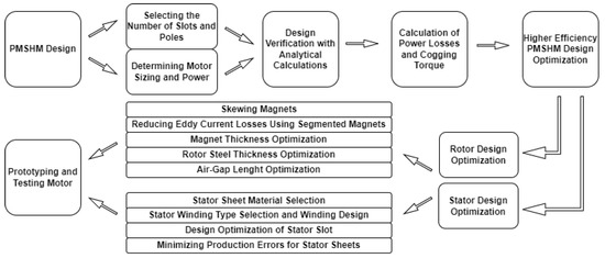
Figure 1.
PMSHM design optimization flowchart.
2.1. Determining the Motor Sizing and Power
When designing the PMSHM with an outer rotor, the power, torque, and speed required by the motor were first determined, and then the motor was dimensioned based on these values. From studies covering this topic in the literature, it is seen that a nominal power of 1.5 kW is sufficient for light EVs such as electric scooters, golf carts, bikes, and rickshaws; moreover, the speed of the light EVs is considered to be in the range of 55–60 km/h [12,13,14]. Thus, in this study, the power of the motor was determined to be 1.5 kW, and the average speed was considered as 550 r/min (57 km/h or 57.59 rad/s) based on a wheel diameter of 550 mm. The motor was then dimensioned for these values. After determining the required power and speed range, the motor torque was calculated using (1) and found to be approximately 26 Nm. Where P represents the mechanical power, T represents the mechanical torque, and represents the angular velocity.
Table 1 lists the sizing data for the proposed motor. The design parameters of the motor were determined based on the analysis carried out using the ANSYS Maxwell software. The electromagnetic torque was then calculated using (2) to observe the agreement between the analysis and analytical results [10]. Equation (2) is given in [10] for an inner rotor PMSM. For this reason, this equation was revised for the outer rotor PMSM in this study and the stator outer diameter () was used instead of the stator inner diameter () in the equation in [10].

Table 1.
Motor Design Parameters.
In Equation (2) where S is the apparent electromagnetic power crossing the air gap, k is the stator winding factor, D is the outer diameter of the stator, cos is the the power factor between the stator current I and input voltage V, L is the axial length of the motor, A is the peak value of the stator line current density according to (3), and B is the peak value of the magnetic flux density in the air gap according to (4). A was calculated to be 30.315 A/m using (3), where is the number of turns per phase, is the peak stator current, and m is the number of phases.
For PMs with a linear demagnetization curve, i.e., NdFeB magnets, the magnetic flux density produced in the air gap can be calculated based on the remanent magnetic flux density Band the relative recoil magnetic permeabilityμ given in (5) as follows.
In this study, an NdFeB N52 magnet with an energy product BH of 50–53 MGOe (398–422 kJ/m) was used in the rotor part of the proposed motor. The NdFeB N52 magnet has an equitable distribution of magnetic flux density, which provides a high quality outcome. For the NdFeB N52 magnet, the remanent magnetic flux density B and magnetic field strength H are 1.45 T and 836 kA/m, respectively [15,16]. Taking the height of the magnet per pole (h) as 3 mm and the air gap thickness (g) as 1 mm, and B were calculated approximately as 1.38 and 1 T, respectively. B can also be initially estimated as B ≈ (0.6...0.8)B for the sizing procedure of NdFeB PMSMs [10].
The electromagnetic torque was then calculated as 25.6 N·m using the parameters presented in Table 1 and taking stator winding factor k as 0.945 [17]. This shows that the design data of the proposed motor at the rated speed agree well with the analytical calculations.
2.2. Selecting the Number of Poles and Slot
Another important design objective is to determine the number of poles and slots for lightweight EV designs. Selecting the appropriate number of poles and slots results in high-efficiency and high torque output, thereby saving motor space. Previous studies have shown that PMSMs with a similar number of poles and slots are widely used in hub motor studies [17,18,19,20,21,22].
Using a high number of poles allows the motor to generate a more sinusoidal back electromotive force, thereby reducing losses when driving the motor. In this proposed motor design, a 36-slot 32-pole design that is among the designs that provide the lowest harmonic loss in the literature was chosen [19]. The number of poles also directly affects the motor frequency, as shown in (6). As the number of poles of the motor increases, frequency increases. Frequency also directly affects the driving performance of the motor. In (6), is the frequency of the motor, is the number of poles, and n is the motor speed in revolutions per minute. The frequency of the 32-pole motor that rotated at an average of 550 r/min was found to be approximately 147 Hz as follows:
In this PMSHM design, in addition to designing a high-efficiency motor, low cogging torque was also considered because the cogging torque causes noise, vibration, jerking motion, and uncomfortable driving in EVs. The cogging torque is directly related to the number of stator slots and rotor poles, as shown in (7) and (8), since it results from the electromagnetic interaction between PMs placed on the rotor and stator teeth [5,11,21,22]. Therefore, when determining the number of slots and poles, low cogging torques were also considered in this study.
The cogging torque can be represented by the following [21,22]:
where is the PM flux that crosses the air gap, R is the reluctance of the air gap, and is the angular position of the rotor. Since the reluctance of the air gap varies periodically, the cogging torque is also periodic. Thus, cogging torques can be written as a Fourier series, as in the following.
In Equation (8), k is an integer, is the Fourier coefficient, and m is both the least common multiple of the number of slots and poles and the cogging torque period per revolution of the rotor.
Considering these initial sizing design parameters, stator and rotor design optimizations are discussed further below.
3. Design Optimization of the PMSHM
The design optimization of the PMSHM has been studied in two parts: rotor and stator optimization.
3.1. Design Optimization of the Rotor
In this study, different rotor design techniques such as rotor magnet skewing, rotor thickness optimization, air gap length optimization, and magnet thickness optimization were analyzed to investigate their effects on PMSM efficiency and cogging torque.
3.1.1. Skewing the Rotor Magnets
In this study, different optimization analyses were performed to reduce the cogging torque. First, the skewing method, which is a well-known approach in the literature, was used. In PMSMs, skewing can be applied to both stators and rotors [23,24,25,26]. In terms of production and cost, skewing the stator has a more positive impact on the cogging torque than skewing the rotor. However, skewing the stator lengthens each winding unit in proportion to the skew angle. As this increases the resistance of the motor and the copper loss, it reduces efficiency. In the case of skewed rotor magnets, the production cost of the magnet increases slightly, but the copper loss is kept to a minimum by not increasing the winding copper length of the motor. Thus, a reduction in the efficiency is prevented. In addition, since the length of the copper winding is lower, the motor weight does not increase, thereby contributing to the efficiency. Based on these analyses, a decision was made to skew the rotor magnets in this study.
Determining the appropriate skew angle is important for minimizing the cogging torque. Therefore, an optimization study was conducted using ANSYS Maxwell software, and the results were analyzed to determine the appropriate angle value. In the analyses, the cogging torque and motor efficiency were evaluated for various skew percentages within the range of 0–0.60. The results are shown in Figure 2.
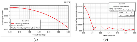
Figure 2.
The influence of magnet skewing on (a) the efficiency and (b) the cogging torque.
As shown in Figure 2, the cogging torque exhibits minimal values at some points and increases at other points depending on the skew percentage. When deciding on the most suitable skew angle, it should be noted that increasing the skew angle makes production difficult. Thus, in this study, the skew percentage was chosen as 0.12, considering the influence of this value on the efficiency. Figure 3 shows the rotor magnets without skewing and with a skew percentage of 0.12.
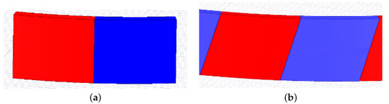
Figure 3.
3D models of the (a) nonskewed and (b) skewed magnets.
Figure 4 shows the cogging torque obtained without skewing and with a skew percentage of 0.12. As shown in Figure 4, the cogging torque can reach up to 422 mN·m without skewing, whereas it can decrease 40 times and drop to as low as 10.39 mN·m with 0.12 skewed magnets. Consequently, the cogging torque successfully decreased by 97.54% with the skewing magnet. The skew angle was then calculated according to Equation (9). The skew percentage was taken as 0.12 and the number of poles as 32 in the equation.
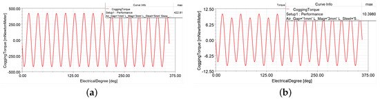
Figure 4.
Cogging torque (a) for the motor without skewing and (b) for the motor with a skew percentage of 0.12.
As observed from (9), the skew angle was found to be 1.35 based on Ansys Maxwell analyses. The optimum skewing angle for a 32-pole 36-slot PMSHM can also be calculated analytically using Equations (10) and (11) given below [22].
In Equation (10), is the number of stator slots, and is the number of cogging torque waveforms during the rotor’s rotation. can be calculated using Equation (11) where is the highest common factor of and . Consequently, the skew angle was found as 1.25 with respect to analytical calculations and 1.35 from the analysis’ results. As observed, there is slight difference between the analytical and analysis results. In the prototyping process, the cogging torque angle was taken as 1.35, which is the same as the analysis’ result.
The hallbach array design, which is another effective method in reducing the cogging torque, has also been simulated in this study. Since at least 2-dimensional (2D) complex hallbach magnet designs are necessary to reduce cogging torque effectively, it will increase the motor cost more than the skewing magnets due to the complex magnet magnetization angles required by the hallbach array. Although the simulation results suggest that the hallbach array increases the motor performance at a similar rate with the skewing method, the skewing method was chosen to reduce the cogging torque considering the motor cost.
3.1.2. Reducing Eddy-Current Losses in Magnets
Among the losses in rotor magnets, the most important one is the eddy current loss, which is called solid loss in ANSYS Maxwell software. In this study, both a segmented magnet structure and epoxy coating in magnets were employed to reduce these losses. The segmented form of the magnets reduces the eddy current loss in proportion to the segmentation square. However, the disadvantage is that the production cost of the motor increases with the number of segments. Considering the cost of the segmented magnet structure and its impact on the efficiency, a two-segment magnet structure was chosen in this study. Figure 5 shows segmented and nonsegmented magnet structures. Magnets are arc shaped and radially magnetized.
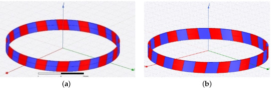
Figure 5.
(a) Segmented skewed magnets. (b) Nonsegmented skewed magnets.
Figure 6 shows the eddy current losses in the motor before and after magnet segmentation. The computed reduction in the eddy current losses was confirmed by electromagnetic analyses, as shown in Figure 6. According to the analyses performed for a torque of 26 N·m and a speed of 550 r/min, the segmentation of the motor magnets resulted in a loss of approximately 7 W instead of 24 W; thus, losses on the magnets reduced by 75%.
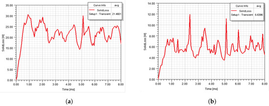
Figure 6.
Eddy current losses for (a) nonsegmented and (b) two-segment magnets.
The eddy current losses P can also be calculated analytically using Equation (12). In (12), h is the height of the magnet and varies depending on the square of the eddy current loss in the magnets [20], B is the flux density of the magnet, f is the frequency of the motor, k is the constant of the material, and is the resistivity of the material.
In the analytical calculation based on (12), when a two-segment magnet is used, the value of h will be taken as h/2; thus, eddy current losses P will decrease to ¼P. This shows that there is accuracy between analysis results and the analytical results. According to the results of the eddy current losses, the efficiency of the proposed 1.5 kW motor increased by 1.13%.
In this study, in addition to using a segmented magnet structure, an epoxy coating was also used in the magnets to reduce eddy current losses in the magnets [27]. The epoxy coating has a minimum resistance of 10·m [28], whereas the NiCuNi coating, which is widely used in magnets, has a maximum resistance of 10·m [29]. Eddy current losses are reduced by using an epoxy coating on the magnets because eddy current losses are known to be higher when the conductivity is high. As shown in (12), the resistivity of the material affects eddy current losses. Therefore, by using epoxy-coated magnets in this design, the eddy current losses in the magnet coating significantly reduced.
The cogging torque analysis was not considered in the segmented magnet motor. This is because, in motor designs where the flux flows along the radial axis, the magnet segmentation in the radial direction affects the cogging torque of the motor, but the segmentation in the axial direction does not have any effect on the cogging torque because it is perpendicular to the rotation of the motor [30].
3.1.3. Optimization of the Magnet Thickness
A magnet’s thickness is a design parameter that affects the cost of the motor, in particular, and has a significant impact on motor performance. As the volume of the magnet increases or its shape becomes more complex, the production cost of the magnet and of the motor increases. Furthermore, the efficiency will decrease since the motor will be heavy because the volume of the magnet is larger than required. Therefore, choosing an appropriate magnet thickness is an important concern in the motor’s design.
In this study, magnet thickness optimization was carried out using ANSYS Electronics Optimetrics software considering cost and motor performance together. The correlation between the magnet thickness and efficiency was also investigated. In addition, the influence of magnet thickness on the cogging torque was taken into account. Figure 7 shows the results of this analysis.
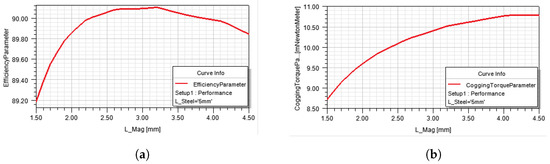
Figure 7.
Effect of magnet thickness on (a) efficiency (b) cogging torque.
As shown in Figure 7, using magnets thicker than 3 mm reduces the efficiency in the same operating range. Therefore, the magnet’s thickness was set to 3 mm. In addition, instead of using unnecessarily large volumes of magnets, using magnets of a smaller volume and lower cost allows the motor to weigh lighter and operate at a higher efficiency.
3.1.4. Optimization of the Air Gap Length
The air gap length and magnetic flux density distribution in the air gap are important design considerations in electric motors because the magnetic flux density in the air gap directly affects the characteristics and performance of the motor. As the air gap length decreases, the magnetic flux density in the air gap increases. Thus, keeping the air gap as small as possible will improve the motor’s performance. When the air gap is selected as a minimum value, the torque constant of the motor increases. Therefore, the motor can rotate at the desired speed and torque, thereby requiring lower power. For this purpose, the air gap flux density in this study varied from 0.5 to 2 mm, and the effects of this variation of the air gap flux density on cogging torque and efficiency were analyzed, as shown in Figure 8, Figure 9 and Figure 10.
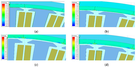
Figure 8.
Magnetic flux density for air gap lengths of (a) 0.5 mm, (b) 1mm, (c) 1.5 mm, and (d) 2 mm.
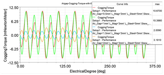
Figure 9.
Cogging torque for different air gap values of 0.5, 0.1, 1, 1.5, and 2 mm for the 0.12 skewed magnet design.
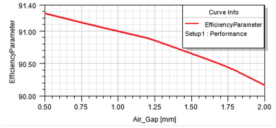
Figure 10.
Motor efficiency for the different air gap lengths.
Figure 8 shows the magnetic flux densities for different air gap lengths. As shown in Figure 8, improved magnetic flux density results were obtained for air-gap lengths of 0.5 and 1 mm. On the other hand, because the distance between the magnets and stator reduced as the air gap decreases, the cogging torque consequently increases, as shown in Figure 9 [15], and efficiency will decrease, as shown in Figure 10. For this reason, both the cogging torque and efficiency were evaluated together in determining the optimum air gap. However, as can be seen in Figure 4b, the cogging torque was considerably reduced by skewing magnets, and the increase in the cogging torque due to the reduction in the air gap reached a value so low that it was negligible.
When these cogging torque and efficiency analyses for different air gap lengths were analyzed together, the air gap was chosen at 1 mm in terms of efficiency and magnetic flux density distribution, although the cogging torque was lower at higher air gap values. The air gap of 0.5 mm was not considered because it increases the production cost, even if the efficiency is higher at this value. As shown in Figure 8, the magnetic flux density in air gap is approximately 1 T for a 1 mm air-gap length. was previously calculated to be approximately 1 T using (4). Considering that the analytical results are in good agreement with the analysis results obtained using ANSYS Maxwell software, it is apparent that the approaches employed in the motor model produce accurate results.
3.1.5. Optimization of the Rotor’s Thickness
A rotor steel structure ensures the flow of magnetic flux between the magnet poles and completion of the magnetic circuit. Therefore, the thickness of the rotor electrical steel affects the motor’s performance. If the selected steel thickness is thin, the flux cannot flow at the desired level; however, the large thickness of the sheet causes an increase in the rotational inertia due to its high mass and decreases the system’s performance.
In addition, since electrical steel is a ferromagnetic material, the electromagnetic interaction between the rotor and stator through this material affects the cogging torque. For this reason, changes in the motor efficiency and cogging torque depending on the rotor’s thickness were studied together. The results are shown in Figure 11.
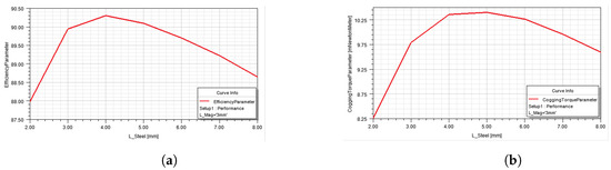
Figure 11.
(a) Efficiency and (b) Cogging torque depending on the rotor steel sheet’s thickness.
First, a rotor thickness of 4 mm was used in the manufacturing process, yielding the best efficiency, as shown in Figure 11; however, a durability problem was encountered when opening the fixing hole in the rotor sheet. When this production difficulty and the magnetic analysis’s results shown in Figure 12 were evaluated together, it was concluded that a rotor thickness of 5 mm is the optimum thickness.
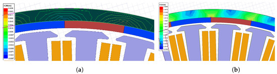
Figure 12.
Results from the electromagnetic analyses for a rotor steel sheet thickness of 5 mm: (a) magnetic flux lines and (b) magnetic flux density.
3.2. Design Optimization of the Stator
The stator structure significantly affects the PMSM performance. For this reason, this study thoroughly investigates some of the important stator parameters that affect motor performance, such as the stator winding structure, stator material, stator lamination thickness, stator slot structure, and methods of stator steel cutting. While conducting analyses on these parameters, optimization studies were carried out by considering the influence of each parameter on efficiency.
3.2.1. Selecting the Stator Winding Structure
The stator winding structure is another important objective in the motor’s design. It is in the inner part of the PMSHM with an outer rotor. Thus, the winding arrangement was considered to ensure that the designed motor met the requirements of light EVs such as high-efficiency and high torque output [17,30]. Two different winding types were adapted and compared in this motor design by considering the skin effect: single flat windings and two parallel windings. Although single flat windings have a larger surface area and less resistance, they cause problems when placed into slots due to their wire thickness. Therefore, two parallel round windings were used in this study. Thus, compared to a single flat winding, the same conductor cross-sectional area can be provided, and because of its thinness, the round winding can be shaped more easily and placed in stator slots. An enamel-coated copper winding with a diameter of 1.5 mm was used in this motor design. With two parallel windings, the number of windings in the motor was doubled to ensure the necessary inductance. Figure 13 shows single flat windings and two parallel round windings. The stator was then constructed with double-wound concentrated windings producing a sinusoidal back emf waveform due to the 36-slot 32-pole configuration.
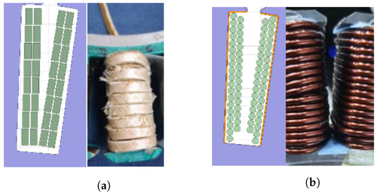
Figure 13.
Stator windings. (a) Single flat winding (b) Two parallel round winding.
The selected winding type was then examined for its skin effect. The motor with a nominal operating speed of 550 r/min was checked to determine whether its frequency created any skin effect on the motor itself. The frequency of the motor was 147 Hz, as previously calculated from (6), and the skin effect value given in (13) was then calculated accordingly. P is the resistivity of copper, f is the frequency of the motor, and µ is the permeability of space in (13).
According to the result from (13), it is seen that, in cases where the radius of the copper winding used in the motor is less than 5.7 mm, there will be no problems encountered due to the skin effect. Because the copper winding used in the proposed motor has a radius of 0.75 mm and is formed by two parallel windings, it is mathematically verified that the skin effect value of the selected winding is acceptable.
3.2.2. Selection of the Stator Sheet Material
The selection of the sheet material of the stator core has a significant influence on the motor performance and core losses. Core losses can be reduced by choosing both the appropriate sheet material and the thinness of the sheets, thus increasing motor efficiency. According to research on the thickness of the sheet, the use of very thin sheets, such as silicone-coat sheets as thin as 0.05 mm, significantly reduces the eddy current loss [31]. However, when very thin sheet plates are used, the cost increases extremely due to the difficulty of production. Therefore, simulation studies were conducted by considering both the production cost of the thin sheet plate and its benefits in terms of core losses [32].
A 20JNEH1200 steel material was used for the stator laminations of the proposed motor. Figure 14 shows the core losses of the 20JNEH1200 material for different sheet thicknesses, where the amount of iron loss per unit weight in the 0.2 mm lamination sheet is lower than that in the lamination sheets with 0.25, 0.30, and 0.35 mm thicknesses [33]. This will certainly contribute to an increase in motor efficiency. A decision was consequently made to use a sheet plate of 0.2 mm in thickness for manufacturing the stator.
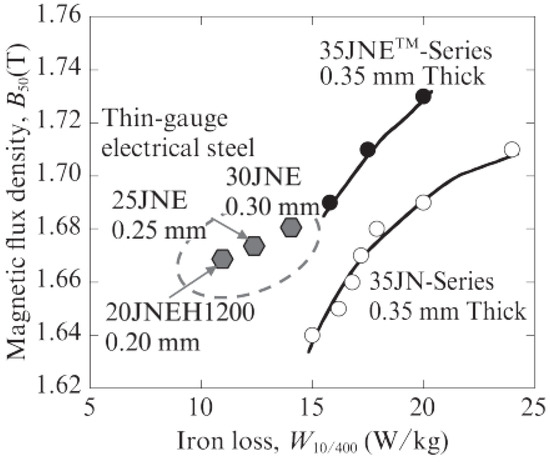
Figure 14.
Core losses of the 20JNEH1200 steel material used in the stator [33].
3.2.3. Stator Slot Design
Stator slot design is an important consideration in motor design to ensure the proper completion of the magnetic circuit in the motor. The slot structure is effective for the magnetic interaction of the rotating magnetic field that occurs in the stator with rotor magnets. For the electromagnetic interaction to be high, the slot’s design must be specific to the motor. Therefore, three different stator slot types were investigated in this study.
As shown in Figure 15, the heights of these three slots are the same; only the designs of the tooth shoe shapes of the stator are different. In the analyses, these design-related differences were examined separately to determine their impact on core losses. Figure 16 shows the results. As observed from the loss analysis, the stator slot type providing the lowest stator loss is Slot−3, as shown in Figure 16c.
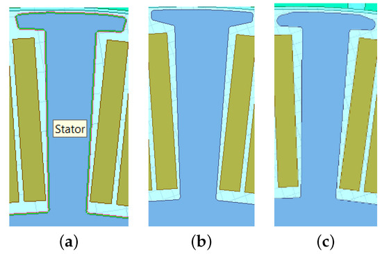
Figure 15.
Stator slot types used in the design: (a) Slot−1; (b) Slot−2; (c) Slot−3.
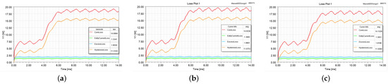
Figure 16.
Stator core losses for (a) Slot−1, (b) Slot−2, and (c) for Slot−3.
Since the different slot types used in the motor directly affect the electromagnetic interaction between the rotor and stator, it also affects the cogging torque. For this reason, three different slot structures were also studied for cogging torque. The results for cogging torque analyses are shown in Figure 17. As observed from the loss analysis, the lowest stator loss was obtained from Slot−3. Likewise, the cogging torque is lower for Slot−3, as shown in Figure 17. For this reason, Slot−3 type was chosen in the motor design. In the analyses, the motor design using the skewed magnet structure was considered.
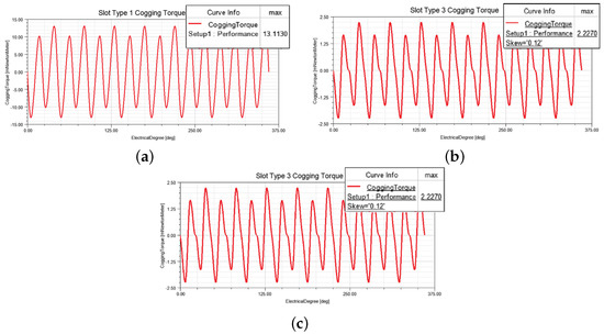
Figure 17.
Effect of the stator slot types on cogging torque for (a) Slot−1, (b) Slot−3, and (c) Slot−3.
3.2.4. Improving the Production Accuracy by Wire-Erosion Cutting
When it comes to the final motor design, deciding on it based simply on successful simulation results is not the best approach. It is also vital that the motor has a design that is suitable for mass production. Because of the impact of air gap variation on motor performance, the stator sheets were cut using a high-precision cutting technique called EDM (Electro Discharge Machining) to ensure air-gap consistency, resulting in a product with a precision of 1 m. Thus, production errors were minimized. In addition to wire erosion, laser cutting was also attempted, but burrs occurred in this case, as shown in Figure 18. Because burring interrupts the magnetic circuit and prevents a homogeneous distribution of the air-gap’s flux density, the wire-erosion technique was chosen.
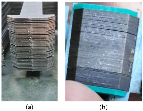
Figure 18.
Comparison of the laser-cut stator and the wire-erosion-cut stator in terms of production tolerance. (a) Laser cutting. (b) Wire erosion cutting.
4. Optimization Design Results
An optimization study of a PMSHM with an outer rotor was carried out to achieve increased motor efficiency and reduced cogging torque. This optimization study covers subjects such as motor sizing, number of slots and poles, material selection, slot shapes, air gap length, magnet thickness, and cutting method with appropriate producibility tolerances.
ANSYS ACT was used to analyze the efficiency of the proposed motor in the simulation. After entering all design parameters for the motor in the ANSYS ACT software, a map of the motor efficiency was obtained by covering varying levels of efficiency at different speeds and torque values. Figure 19a shows the results of the motor efficiency analysis. In Figure 19a, the x-axis represents the motor speed, the y-axis represents the motor torque, and the color change along the z-axis shows the motor efficiency. In the literature conducted to determine the speed and torque of the motor, it was concluded that a speed of 55–60 km/h is required for light EVs and an average torque range of 15–25 N·m would be sufficient [13,14]. Considering these studies, the efficiency of the motor at 550 r/min was examined and obtained to be 93.96%, as shown in Figure 19a. The torque variation at this speed was also analyzed, and the results are shown in Figure 19b. It can be seen that the torque fluctuation is minimized. With a torque output of 23 N·m, a fluctuation of 1 N·m was observed; therefore, a 4.5% fluctuation occurred in the torque. Since the rotor has skewed magnets and the stator has concentrated windings with a 36-slot 32-pole configuration, the back emf waveform is sinusoidal, as seen in Figure 19c.
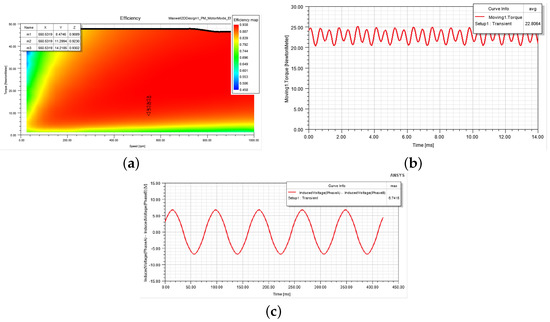
Figure 19.
ANYSYS Maxwell 2D ACT Analaysis results for (a) efficiency, (b), torque at 550 r/min, and (c) back emf waveform.
In the design process of the motor, the aim is to create a design that can work even in situations where high torque is required, such as hills. Therefore, as shown in Figure 19a, the motor can continue to operate above the average torque zone, such as 50 Nm.
5. Prototyping and Testing of The Motor
A prototype of the motor was manufactured based on the results of the simulation and optimization studies using ANSYS Maxwell software. The prototyping of the motor was performed in the laboratory of Yildiz Technical University, Alternative Energy Systems Society (AESK). To start the production process of the motor, stator sheets were cut using the wire-erosion cutting method described above, as shown in Figure 18. The windings were then wounded on the cut stator sheets, and the magnets were placed on the rotor. The stator phase windings were then attached end-to-end to form a star point. After completing the production of the rotor and stator, they were placed on the test stand, mounted on each other with axial movements, and prepared for testing. The production stages are detailed below.
5.1. Stator Production
To produce the stator, stator sheets were first cut using the wire-erosion cutting technique. The stator core was then built with thin laminated steel sheets stacked on each other until the decided length of the stator sheet package is reached. After stacking the stator sheets, stator slots were insulated with insulating paper, and two parallel stator windings were inserted into the slots, as shown in Figure 20. Following the winding process, the star connection point of the motor was created, and the stator production was completed.
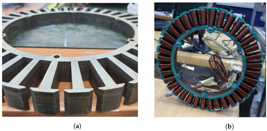
Figure 20.
Stator structure of the motor: (a) stacking of the stator sheets cut using the wire-erosion cutting technique and (b) stator slots with winding.
After the stator assembly was completed, the temperature characteristics of the phases were examined using a thermal camera, as shown in Figure 21b. The thermal limits of some materials used in the motor are given below:
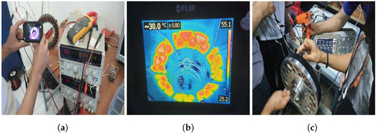
Figure 21.
(a) Checking the phases with the thermal camera. (b) Positioning of the position sensor.(c) Positioning of the position sensor.
- -
- Demagnetization temperature of N52M series Magnets is 100 C.
- -
- Class C insulation material thermal limit of the windings is 220 C.
- -
- The thermal limit of the stator insulation paper is 180 C.
For the thermal test of the motor, a constant current from a power supply was applied to the each phase for 1-hour to determine whether there was any difference between the phases. It was observed that it did not rise above 60 C. Since this value is below the thermal limits given above, no thermal problems have been experienced in the motor. The image taken from the thermal camera of the motor during the test is given in Figure 21b. Three Hall effect sensors were then installed to monitor the motor. Each Hall effect sensor was positioned steadily to match a phase, and this positioning was determined according to the display on the oscilloscope, as shown in Figure 21c.
5.2. Rotor Production
Rotor production began with the cutting of the rotor steel in the CNC machine. To attach the rotor cover to the steel rotor, holes were drilled, and the steel rotor production was completed. The magnets were then carefully placed on the rotor steel in a segmented and skewed form.
The magnets adhered with a resin-based adhesive and was baked at 60 C, allowing the adhesive to dry quickly. As shown in Figure 22b, skewing and segmentation were performed as close as possible to those designed using ANSYS software. Steel C1050 was used to manufacture the rotor, and NdFeB N52 was chosen as the PM material for the rotor.
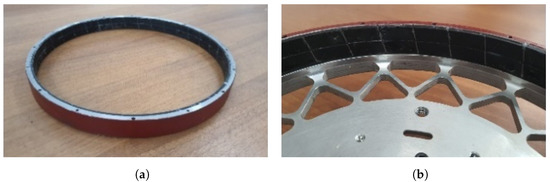
Figure 22.
(a) Rotor structure. (b) Magnet segmentation.
5.3. The Motor Testing and Results
After the prototype of the motor was manufactured, the rotor and stator were mechanically mounted on each other and placed on the test bench. The test setup consisted of an eddy current load, first coupling, a torque sensor, second coupling, and the motor. The couplings were used to reduce the axial misalignment. Mechanical power was obtained from the test setup using the torque value read from the torque sensor and the speed information read from the Hall effect sensor located on the motor. After the electrical power was calculated using the current and input voltages, the motor efficiency was obtained based on the ratio of mechanical power to electrical power.
The prototyped motor was then tested using the motor test setup at Alternative Energy Systems Society (AESK) R&D Laboratory at Yildiz Technical University, as shown in Figure 23 and the test results are given in Table 2. As seen in Table 2, the motor has reached a higher efficiency of 92.5% with the mechanical load at the 7.5 V Eddy Brake voltage shown in bold in the Table 2. When the simulation results and experimental results are compared, it is seen that the Eddy Set Voltage values of the motor given in Table 2 are quite consistent with the simulation results given in Figure 19. The 6.5 V, 7.5 V and 8.5 V values in Table 2 show similar speed and torque values with the m1, m2 and m3 points given in Figure 19. For example, while the efficiency value is 92.5% in Table 2 at Eddy Set Voltage of 6.5 V, it is seen as 92.3% in the ANSYS Maxwell ACT efficiency graph in Figure 19 at the same torque and speed values. As seen the comparison, there is a good agreement between the simulation results and test results. This small difference is due to the losses caused by the motor driver used, which affect the motor efficiency, and the friction in the mechanical parts of the motor testing mechanism. When compared to other motors in light EVs of the same power level in the literature, this level of efficiency can be considered high [1,3,12,34,35].
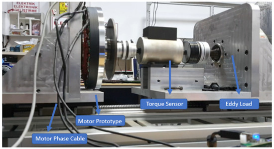
Figure 23.
At-load testing of the motor on the test setup.
Table 2.
Efficiency measurement under constant speed and varying torque on the motor’s test.
The back emf waveforms at 45 rpm taken from the analysis result and the oscilloscope are shown in Figure 19c and Figure 24. The sinusoidal back emf waveform is essential for the smooth operation of PMSMs. Since the rotor has skewed magnets and the stator has concentrated windings with a 36-slot 32-pole configuration, the back emf waveform is sinusoidal in both figures. It also results in low torque ripple and high efficiency [9]. The maximum back emf value of the motor at 45 rpm is 7.14 V and 6.74 V for experimental and analysis results, respectively. The difference between the analysis and experimental study results is about 5.9%.
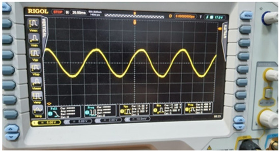
Figure 24.
Back emf waveform from the test setup.
The prototyped motor was then tested by installing it on a prototype electric vehicle wheel, as shown in three different pictures in Figure 25. The performance of the hub motor in the road test was evaluated on subjects, such as whether the motor could be driven properly with the motor driver; the power values demanded from the battery; the maximum speed of the motor at the battery voltage in the vehicle; whether the motor could reach the thermal limits; and whether it could meet the instant torque demand for the vehicle in the hill-start test. During this test drive, the motor performed successfully and operated compatibly with the rest of the electric vehicle systems.
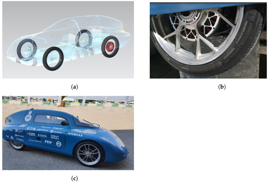
Figure 25.
(a) The position of the hub motor on the vehicle. (b) Hub motor mounted on the wheel. (c) Light electric race car with the prototyped motor.
This light EV doesn’t need all-wheel drive like highway driving needs, so only a left-rear hub motor was used during light EV tests as seen in Figure 25a. Thanks to this motor’s transmission system, the power to each wheel could be controlled and the vehicle handling was optimized. Also, due to it being a lighter electrical vehicle and lower rolling resistance, the torque on the hub motor wheel would be enough to drive the other three wheels. Conversely, using a hub motor for each wheel makes suspension design and control system very complex. It makes the EV less efficient due to high friction loss in the transmission system and mechanical losses such as bearing and ventilation loss. It also makes cooling the motors pretty hard. In addition, it increases unsprung mass, making the EV heavier and more expensive. Similar to this light EV concept, most EVs today only drive one or two wheels instead of 4 wheels like Tesla and Jaguar.
In this multi-objective optimization of PMSM used for light EVs, more consideration was given to efficiency, low cogging torque, and operating performance. It is predicted that this porotype PMSHM is a unique design, and its cost is higher than ones produced in large quantities. The cost of the motor is about 1000USD and the percent distribution of this cost is illustrated in Figure 26. The proposed motor contains high-cost rare-earth magnet materials. Therefore, the magnet’s cost is the highest in the cost distribution.
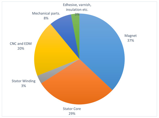
Figure 26.
Percent distribution of the cost categories of the proposed motor.
6. Conclusions
In this study, a PM hub motor design was developed for light EVs. In the first stage of the study, the hub motor model was created using ANSYS Maxwell software, and electromagnetic analyses were performed. In these analyses, different motor models were created, simulated, and optimized. The final motor design was then achieved based on the optimization results. In the optimization study, different design parameters, such as magnet thickness, skewed magnet structure, magnet segmentation, air gap length, stator winding thickness, slot structures, and lamination thicknesses of the stator and rotor, were considered. As a result of the optimization, a PM hub motor with low cogging torque, high-efficiency, and low cost was developed for light EVs. Because this motor is used directly as a hub motor without a loss of transmission, its efficiency is as high as 93%. The proposed motor was then manufactured and tested on a test stand under load, at the speed and torque values required for light EVs. The test and analysis results were compared, and it was observed that the torque, power, and speed results were in good agreement. After tests were completed, the hub motor was installed on a prototype EV, and the test drive was successfully performed.Finally, a higher efficiency motor was designed than those in the literature.
This study is intended as a reference for the widespread use of energy-efficient light EVs in the future. If this study is advanced, a more efficient and cost-effective design can be developed, and this model can then be used in commercial EVs.
Author Contributions
Conceptualization, İ.G.Ç. and S.Z.P.; methodology, İ.G.Ç. and S.Z.P.; software, İ.G.Ç. and S.Z.P.; validation, İ.G.Ç. and S.Z.P.; formal analysis, İ.G.Ç. and S.Z.P.; investigation, İ.G.Ç. and S.Z.P.; resources, İ.G.Ç. and S.Z.P.; data curation, İ.G.Ç.; writing—original draft preparation, İ.G.Ç. and S.Z.P.; writing—review and editing, S.Z.P.; visualization, İ.G.Ç. and S.Z.P.; supervision, S.Z.P.; project administration, S.Z.P.; funding acquisition, İ.G.Ç. All authors have read and agreed to the published version of the manuscript.
Funding
This research was partly funded by the Scientific and Technological Research Council of Turkey (TUBITAK) grant number 1139B412000372.
Acknowledgments
We would like to thank all the YTU Alternative Energy Systems Society (AESK) members for their support in this work. This prototype EV further participated in Efficiency Challenge Race organized by the Scientific and Technological Research Council f Turkey (TUBITAK). In this race, the prototype EV completed the race course of 60 km with 631 W·h, and it was selected as the most efficient vehicle in the 16-year-old competition in the electromobile category and completed the race in the first place.
Conflicts of Interest
The authors declare no conflict of interest.
References
- Celtek, S.A. Effects of electric motors on the energy efficiency. In Proceedings of the 8th International Ege Energy Symposium & Exhibition, Karahisar, Turkey, 11–13 May 2015. [Google Scholar]
- Dambrauskas, K.; Vanagas, J.; Zimnickas, T.; Kalvaitis, A.; Ažubalis, M. A method for efficiency determination of permanent magnet synchronous motor. Energies 2020, 13, 1004. [Google Scholar] [CrossRef]
- Jiang, X.; Chen, L.; Xu, X.; Cai, Y.; Li, Y.; Wang, W. Analysis and optimization of energy efficiency for an electric vehicle with four independent drive in-wheel motors. Adv. Mech. Eng. 2018, 10, 1687814018765549. [Google Scholar] [CrossRef]
- Loganayaki, A.; Kumar, R.B. Permanent magnet synchronous motor for electric vehicle applications. In Proceedings of the 2019 5th International Conference on Advanced Computing & Communication Systems (ICACCS), Coimbatore, India, 15–16 March 2019; pp. 1064–1069. [Google Scholar] [CrossRef]
- Gieras, J.F. Analytical approach to cogging torque calculation in PM brushless motors. In Proceedings of the IEEE International Electric Machines and Drives Conference, IEMDC’03, Madison, WI, USA, 1–4 June 2003; Volume 2, pp. 815–819. [Google Scholar] [CrossRef]
- Saied, S.A.; Abbaszadeh, K. Cogging torque reduction in brushless DC motors using slot-opening shift. Adv. Electr. Comput. Eng. 2009, 9, 28–33. [Google Scholar] [CrossRef]
- Dal, Ö.; Yıldırım, M.; Kürüm, H. Optimization of permanent magnet synchronous motor design by using PSO. In Proceedings of the 2019 4th International Conference on Power Electronics and their Applications (ICPEA), Elazig, Turkey, 25–27 September 2019; pp. 1–6. [Google Scholar] [CrossRef]
- Kawase, Y.; Yamaguchi, T.; Tu, Z.; Toida, N.; Minoshima, N.; Hashimoto, K. Effects of skew angle of rotor in squirrel-cage induction motor on torque and loss characteristics. IEEE Trans. Magn. 2009, 45, 1700–1703. [Google Scholar] [CrossRef]
- Libert, F.; Soulard, J. Investigation on pole-slot combinations for permanent-magnet machines with concentrated windings. In Proceedings of the International Conference on Electrical Machines and Systems 2004, Lodz, Poland, 1–3 November 2004; pp. 5–8. [Google Scholar]
- Jacek, F. Gieras “Permanent Magnet Motor Technology”, 3rd ed.; CRC Press: Boca Raton, FL, USA, 2010; ISBN 978-1420064407. [Google Scholar]
- Zhu, Z.Q.; Howe, D. Influence of design parameters on cogging torque in permanent magnet machines. IEEE Trans. Energy Convers. 2000, 15, 407–412. [Google Scholar] [CrossRef]
- Jiang, X.; Chen, L.; Xu, X.; Cai, Y.; Li, Y.; Wang, W. Design optimisation of an outer-rotor permanent magnet synchronous hub motor for a low-speed campus patrol EV. IET Electr. Power Appl. 2020, 14, 2111–2118. [Google Scholar] [CrossRef]
- Lee, J.Y.; Woo, B.C.; Kim, J.M.; Oh, H.S. In-wheel motor design for an electric scooter. J. Electric. Eng. Technol. 2017, 12, 2307–2316. [Google Scholar] [CrossRef]
- Song, B.; Choi, J. A low-speed high-torque permanent magnet motor for electric scooters. In Proceedings of the 2011 IEEE Vehicle Power and Propulsion Conference, Chicago, IL, USA, 6–9 September 2011; pp. 1–6. [Google Scholar] [CrossRef]
- Tariq, A.R.; Nino-Baron, C.E.; Strangas, E.G. Consideration of magnet materials in the design of PMSMs for HEVs application. IEEE Power Energy Soc. Gen. Meet. 2011, 2011, 6039824. [Google Scholar] [CrossRef]
- Hiron, N.; Andang, A.; Busaeriet, N. Investigation of NdFeB N52 magnet field as advanced material at air gap of axial electrical generator. IOP Conf. Ser. Mater. Sci. Eng. 2019, 550, 012034. [Google Scholar] [CrossRef]
- Martínez, D. Design of a Permanent-Magnet Synchronous Machine with Non-Overlapping Concentrated Windings for the Shell Eco Marathon Urban Prototype (Dissertation). 2012. Available online: http://urn.kb.se/resolve?urn=urn:nbn:se:kth:diva-109741 (accessed on 16 October 2022).
- Li, L.; Zhang, J.; Zhang, C.; Yu, J. Research on electromagnetic and thermal issue of high efficiency and high-power density outer-rotor motor. IEEE Trans. Appl. Supercond. 2016, 26, 1–5. [Google Scholar] [CrossRef]
- Sudha, B.; Vadde, A.; Sachin, S. A review: High power density motors for electric vehicles. In Proceedings of the Journal of Physics: Conference Series, Volume 1706, First International Conference on Advances in Physical Sciences and Materials, Coimbatore, India, 13–14 August 2020. [Google Scholar]
- Hanselman, D.C. Brushless Permanent Magnet Motor, 2nd ed.; The Writers’ Collective: Cranston, RI, USA, 2003; ISBN 978-1932133639. [Google Scholar]
- Hwang, C.C.; Wu, M.H.; Cheng, S.P. Influence of pole and slot combinations on cogging torque in fractional slot PM motors. J. Magn. Magn. Mater. 2006, 304, e430–e432. [Google Scholar] [CrossRef]
- Sayed, A.E.; Erturk, E. Minimizing cogging torque in permanent magnet synchronous generators for small wind turbine applications. Int. J. Renew. Energy Res. 2021, 11, 691–700. [Google Scholar]
- Hsiao, C.; Yeh, S.; Hwang, J. A novel cogging torque simulation method for permanent-magnet synchronous machines. Energies 2011, 4, 2166–2179. [Google Scholar] [CrossRef]
- Islam, R.; Husain, I.; Fardoun, A.; McLaughlin, K. Permanent-magnet synchronous motor magnet designs with skewing for torque ripple and cogging torque reduction. IEEE Trans. Ind. Appl. 2009, 45, 152–160. [Google Scholar] [CrossRef]
- Dalcalı, A.; Kurt, E.; Çelik, E.; Öztürk, N. Cogging torque minimization using skewed and separated magnet geometries. J. Polytech. 2020, 23, 223–230. [Google Scholar] [CrossRef]
- Nam, D.-W.; Lee, K.-B.; Pyo, H.-J.; Jeong, M.-J.; Yang, S.-H.; Kim, W.-H.; Jang, H.-K. A study on core skew considering manufacturability of double-layer spoke-type PMSM. Energies 2021, 14, 610. [Google Scholar] [CrossRef]
- Jagadeeshwaran, A.; Padma, S. Comparative study of cogging torque for different tooth gap width and airgap flux of PMBLDC motor for motion control applications. Int. J. Electr. Eng. 2012, 5, 783–790. [Google Scholar]
- Fernandez, D.; Reigosa, D.; Guerrero, J.M.; Zhu, Z.Q.; Suarez, C.; Briz, F. Influence of PM coating on PM magnetization state estimation methods based on magnetoresistive effect. IEEE Trans. Ind. Appl. 2018, 54, 2141–2150. [Google Scholar] [CrossRef]
- Lee, H.; Neville, K. Handbook of Epoxy Resins, 1st ed.; McGraw-Hill: New York, NY, USA, 1967; ISBN 978-0070369979. [Google Scholar]
- Lateb, R.; Takorabet, N.; Meibody-Tabar, F. Effect of magnet segmentation on the cogging torque in surface-mounted permanent-magnet motors. IEEE Trans. Magn. 2006, 42, 442–445. [Google Scholar] [CrossRef]
- Hong, D.-K.; Lee, T.-W.; Jeong, Y.-H. Design and Experimental Validation of a High-Speed Electric Turbocharger Motor Considering Variation of the L/D Ratio. IEEE Trans. Magn. 2018, 54, 1–4. [Google Scholar] [CrossRef]
- Novak, G.; Kokošar, J.; Nagode, A.; Petrovic, D.S. Core-loss prediction for non-oriented electrical steels based on the Steinmetz equation using fixed coefficients with a wide frequency range of validity. IEEE Trans. Magn. 2014, 51, 1–7. [Google Scholar] [CrossRef]
- Yoshihiko, O.; Masaaki, O.T.T. Recent Development of Non-Oriented Electrical Steel in JFE Steel. JFE Tech. Rep. 2016, 21, 7–13. [Google Scholar]
- Garip, S.; Yasa, Y. Design of outer runner-type brushless permanent magnet DC motor for light-weight E-vehicles. In Proceedings of the 2020 6th International Conference on Electric Power and Energy Conversion Systems (EPECS), Istanbul, Turkey, 5–7 October 2020; pp. 151–156. [Google Scholar] [CrossRef]
- Abhilash, D.S.H.; Wani, I.; Joseph, K.; Jha, R.; Haneesh, K.M. Power efficient e-bike with terrain adaptive intelligence. In Proceedings of the 2019 International Conference on Communication and Electronics Systems (ICCES), Coimbatore, India, 17–19 July 2019; pp. 1148–1153. [Google Scholar] [CrossRef]


Publisher’s Note: MDPI stays neutral with regard to jurisdictional claims in published maps and institutional affiliations. |
© 2022 by the authors. Licensee MDPI, Basel, Switzerland. This article is an open access article distributed under the terms and conditions of the Creative Commons Attribution (CC BY) license (https://creativecommons.org/licenses/by/4.0/).