Article

Robust Suppression Strategy for Photovoltaic Grid-Connected Inverter Cluster Resonance Based on Kalman Filter Improved Disturbance Observer

1
School of Electrical and Control Engineering, Henan University of Urban Construction, Pingdingshan 467036, China
2
College of Electrical Engineering & New Energy, China Three Gorges University, Yichang 443002, China
3
Ningbo Deye Technology Co., Ltd., Ningbo 315803, China
*
Author to whom correspondence should be addressed.
Energies 2022, 15(21), 7942; https://doi.org/10.3390/en15217942
Submission received: 17 September 2022 / Revised: 17 October 2022 / Accepted: 22 October 2022 / Published: 26 October 2022
(This article belongs to the Special Issue Advanced Grid Integration with Power Electronics)

Abstract

:
In response to the key engineering problems of photovoltaic grid-connected inverter cluster resonance suppression affected by grid-connected inverter impedance, in this paper, a control strategy based on a disturbance observer is proposed to dynamically compensate for the damping coefficient of the controlled system and improve the robustness of the system. First, an engineering mathematical model of a 200 MW photovoltaic inverter cluster is established, and the mechanism of the active damping of the cluster inverter influenced by the disturbance is analyzed. Secondly, the capacitor current feedback is utilized to constitute the virtual damping, and the inverter output impedance is reshaped to suppress the resonance peak. Then, a Kalman filter is used to improve the traditional disturbance observer to accurately detect disturbance of the system during the dynamic process of the cluster inverter so as to better adapt to changes in grid impedance and dynamically compensate for the virtual damping of the cluster resonant system. Finally, the proposed control strategy is verified with respect to a practical PV power station. The experimental results demonstrate the feasibility of the proposed control method.

1. Introduction

With the development of new energy grid-connected control technology, the penetration of photovoltaic energy is increasing, and the development trend of large-scale photovoltaic power plants is becoming increasingly prevalent. In large photovoltaic power stations, the photovoltaic cluster is composed of grid-connected inverters through their respective LCL filters, bus, distribution transformers and distribution lines and connected with the high-voltage power grid through a centralized boost transformer. The essential reasons for the resonance of photovoltaic cluster inverters are summarized as follows: there is a coupling between the LCL filter, the impedance of the distribution transformer and the inductance of the distribution line among the inverters in the photovoltaic cluster, easily forming a complex, high-order network; interaction also occurs between the inverter cluster and grid impedance. Because influence of the power quality of the inverter output exceeds the maximum standard limit, the photovoltaic inverter is forced to withdraw from operation; the safety, reliability and economic indicators of photovoltaic power generation are also directly affected [1,2,3,4,5,6,7]. The resonance suppression of photovoltaic power plants has become a key factor restricting the development of large-scale photovoltaic power plants, so it is of considerable significance to investigate the resonance suppression of photovoltaic power plants.
With respect to the interaction mechanism of grid-connected inverters, in reference [8], the grid impedance was considered in a grid-connected system of a large-scale photovoltaic power station; an equivalent circuit model of a three-phase LCL grid-connected inverter parallel system was established according to the topology and working principle of a large-scale photovoltaic power station. With the aim of establishing an equivalent circuit model, the influence of grid impedance on the current control of a grid-connected inverter in a large-scale photovoltaic power station was analyzed using the traditional frequency domain analysis method, showing that an increase in the number of inverters affects the stability of the entire inverter parallel system. A Norton equivalent model of a three-phase inverter parallel system was established in reference [9], and the expression of inverter grid-connected current, grid-connected common point voltage and the closed-loop characteristic equation of a large-scale, grid-connected photovoltaic system were deduced, enabling a root locus analysis of the influence of grid impedance on the stability of a large-scale, grid-connected photovoltaic system, proving that an increase in the number of inverters increases the resistance of the equivalent line group on the grid-connected side, thus affecting the stability of the whole inverter parallel system. In view of the interaction between the inverter side and the grid side when a large number of distributed, grid-connected inverters is connected to the public grid, Zhou and Zhang [10] proposed a new method of output impedance modeling for an LCL-type three-phase, grid-connected inverter with a double closed-loop system of grid current and filter capacitor current considering the dead effect with respect to the influence of different dead effects on the output harmonics of the multi-inverter parallel system. Yan et al. [11] proposed a control model of parallel system of multiple photovoltaic inverters based on the research background of a weak grid, explaining the influence of an increase in grid impedance and the number of parallel inverters on a single inverter, i.e., an increase in grid equivalent impedance from the perspectives of power quality, dynamic response and system stability.
Many methods are available to maintain the stability of inverter parallel systems. From the perspective of improving the performance of the inverter, an active harmonic conductance method was proposed in [12]. Without changing the circuit topology, a conductance loop was added to the harmonic current to adjust the equivalent output impedance of a single inverter. The output of the harmonic current of the inverter was effectively suppressed, the anti-interference ability of the inverter was improved and the resonance phenomenon was avoided. However, for a multi-inverter parallel system, this method would not only increase the system loss but also increase the overall circuit volume and cost. An active damping control strategy was devised in reference [13] based on a closed-loop control model of a multi-inverter, grid-connected system. On the basis of a multi-inverter, grid-connected topology, a closed-loop mathematical model of a multi-inverter, grid-connected system was established according to the Thevenin equivalent theorem. The resonance mechanism between multiple inverters was investigated, and the grid resonance was suppressed via active damping through the capacitor current. However, this model does not consider the interaction between parallel inverters and cannot adapt to the disturbance caused by changes in grid impedance. In reference [14], in response to parameter disturbance of an LCL filter, a nonlinear sliding-mode observer was utilized to detect the output current to compensate for the current harmonics generated by the nonlinear load so as to maintain the stability of the internal current loop. Although the number of current sensors was reduced, the impact of high-frequency measurement noise was suppressed and the overall cost was reduced, the designed sliding-mode observer had a complex structure and was not easy to implement, making it unable to adapt to the disturbance caused by grid impedance changes. In reference [15], an adaptive linear auto-disturbance rejection control technique was used to reduce the influence of inverter filter parameter perturbation on the output harmonics. Despite overcoming the shortcomings of traditional auto-disturbance rejection technology, it is difficult to determine the optimal parameters and suppresses changes in the resonant frequency of the filter itself. Furthermore, the implementation process of the controller itself is complex, the control bandwidth is narrow, and the process of adaptively determining the optimal parameters requires a number of calculations and therefore a microprocessor with a high capacity and fast operation speed, increasing the overall cost of the circuit.
Although the abovementioned studies analyzed the resonance mechanism of photovoltaic power plants from perspectives and proposed corresponding resonance suppression strategies, few literature studies have investigated the influence of the cut-in and cut-out of the cluster inverter on the robustness of the resonant suppression strategy in the dynamic operation of a real large-scale photovoltaic power station [16]. By considering the grid impedance, an equivalent impedance model and control system model of an inverter grid-connected system under a weak grid were established in reference [17], revealing the key cause of system oscillation, i.e., that the grid-connected system has insufficient damping near the resonant frequency. Therefore, in order to effectively solve the resonance problem when multiple inverters are connected to the grid, based on the traditional active damping suppression of inverter cluster resonance, in this paper, we propose an improved disturbance observer to observe the disturbance generated by the cut-in and cut-out process of the cluster inverter to dynamically compensate for the virtual damping parameters, thereby effectively suppressing the cluster dynamic resonance.

2. Mathematical Modeling of a Photovoltaic Inverter Cluster

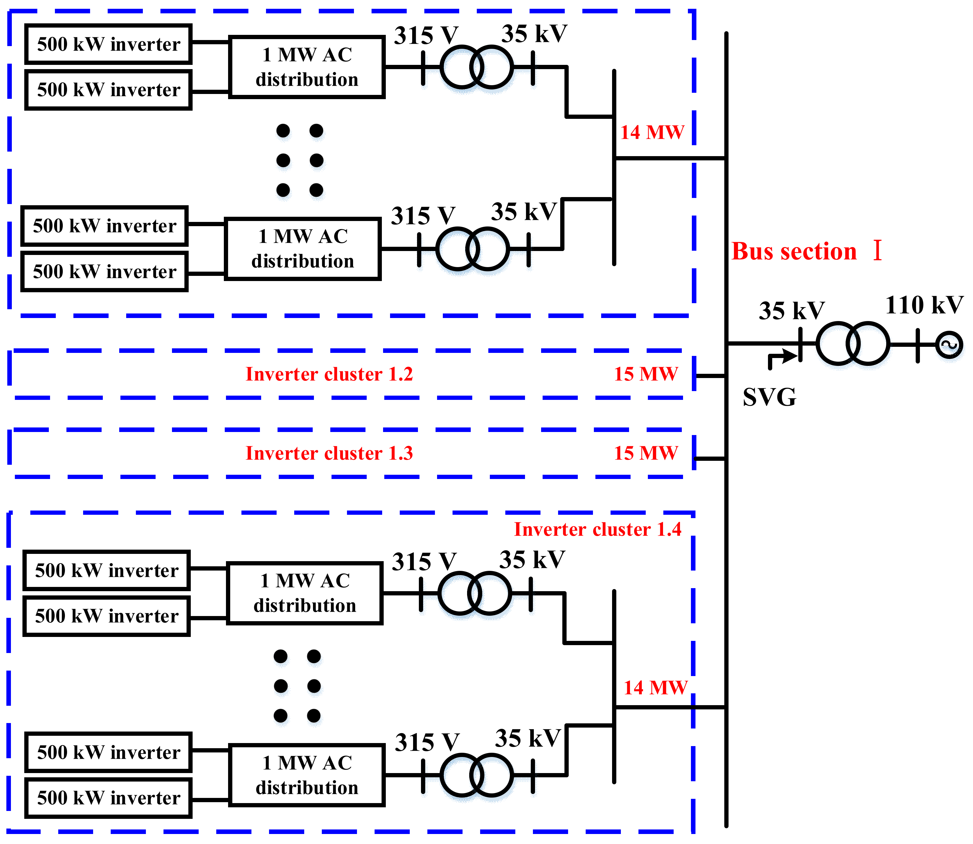
A 200 MW photovoltaic power station was taken as the research object in this study. Figure 1 shows a structural diagram of the investigated power station.
The power generated by the 200 MW photovoltaic power station is collected on four AC buses. Considering the bus load balance, each AC bus collects about 50 MW, and the power on each bus section comes from multiple inverter clusters.
Figure 2 shows a schematic diagram of bus I of the 200 MW photovoltaic power station; the inverter cluster corresponding to the bus is the same as this structure.
The power of bus I comes from four inverter clusters, and the power of each inverter cluster is between 10 MW and 15 MW.
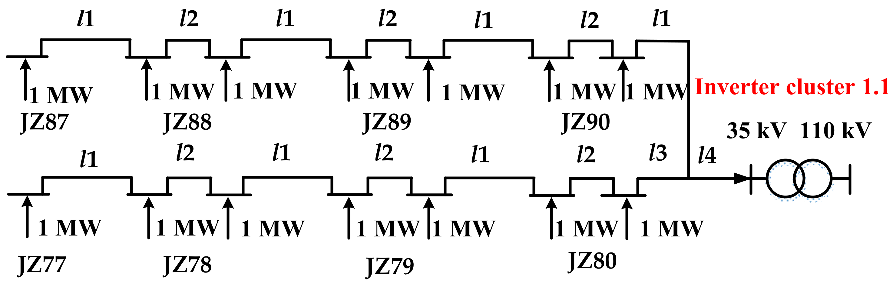
Each inverter cluster includes several megawatt-level inverter modules. A structural diagram of inverter cluster no. 1.1 in bus I is shown in Figure 3.
As shown in Figure 3, the inverter unit farthest from the point of common coupling (PCC) node is inverter unit JZ87, and the inverter unit closest to the PCC node is inverter unit JZ80. In this inverter cluster, the line average impedance of each inverter unit is approximately taken as the equivalent impedance of a single inverter cluster. There are four inverter clusters in bus I, and the average impedance of the four inverter clusters is taken as the equivalent impedance of bus I. Finally, the equivalent impedance of bus I is taken as the equivalent impedance of the grid side of a single-megawatt inverter unit.
The equivalent structure of the 200 MW photovoltaic power station is shown in Figure 4.
In Figure 4, L
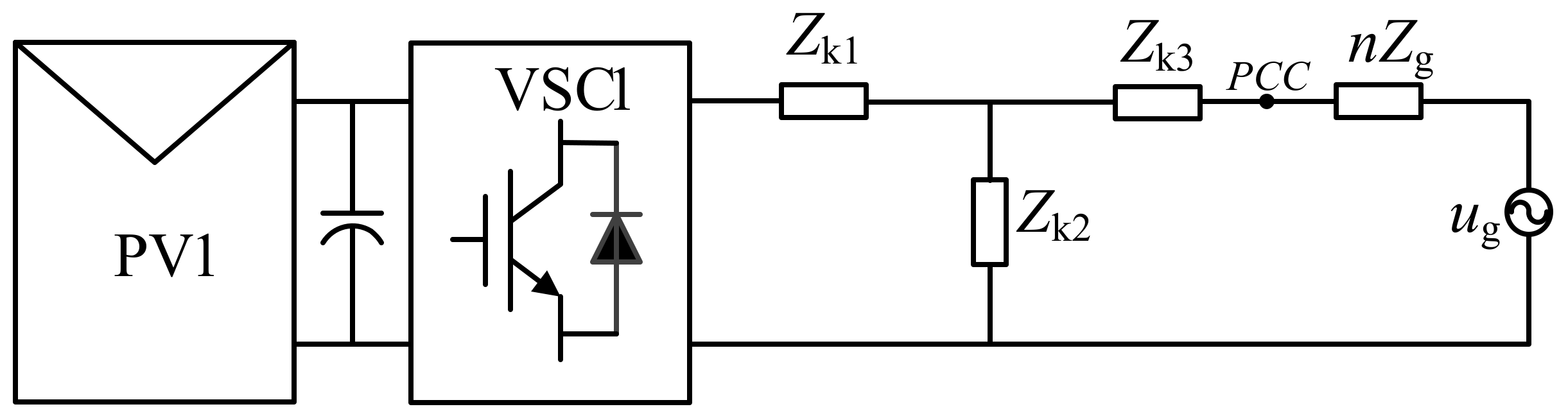
eq is the equivalent reactance after converting the side impedance of the isolation transformer to the 35 kV side. The equivalent circuit of one of the n inverters in the grid-connected system can be derived from Figure 4, as shown in Figure 5.
In Figure 5, each photovoltaic inverter is coupled to the grid through the LCL filter at PCC, where Zk1, Zk3 and Zk2 are the inverter-side inductance, grid-side inductance and filter capacitor, respectively; PV is the photovoltaic module; and Zg is the equivalent impedance of the grid. Assuming that the hardware and software parameters of n grid-connected inverters are consistent, the equivalent grid impedance of one inverter in the nth grid-connected system is increased by n times that of the single inverter, that is, Zg = n × Zg.

3. Analysis of the Resonant Mechanism of the Cluster Inverter

Utilizing the established inverter cluster model, a inverter cluster resonance model with an equivalent disturbance source can be further obtained to investigate how active damping affects multiple grid-connected inverters.

3.1. Inverter Cluster Resonance Model with an Equivalent Disturbance Source

Figure 6 shows the equivalent control block diagram of a single inverter in parallel with multiple inverters.
The open-loop transfer function of the equivalent grid-connected current of the grid-connected inverter can be derived from Figure 6, as shown in (1).
G 1 e q _ n ( s ) = k p w m k f i ( k p i s + k i i ) ( ( n l g + l 2 ) C 1 s 2 + 1 ) s 2 ( ( n l g + l 2 ) C 1 s 2 + l 1 + ( n l g + l 2 ) )
The equivalent open-loop Bode waveforms of inverters when the number of grid-connected inverters is 1, 50, 100, 200, 300 and 400 can be obtained through (1), as shown in Figure 7. With an increase in the number of grid-connected inverters, the resonant frequency point of the equivalent inverter gradually changes to the low-frequency direction. Furthermore, with an increase in the number of inverters, the bandwidth is reduced, affecting the dynamic performance of the inverter and slowing down the response speed of the system.

3.2. Multiple Grid-Connected Inverters with Active Damping Suppression

Figure 8 shows an equivalent closed-loop control block diagram of one of the multiple inverters connected to the grid, in which active damping is applied as a resonance suppression strategy.
The equivalent open-loop transfer function of active damping with capacitor current feedback can be deduced as follows:
G e q _ n ( v r ) ( s ) = k p w m k f i ( k p i s + k i i ) ( ( n l g + l 2 ) C 1 s 2 + 1 ) s 2 ( ( n l g + l 2 ) l 1 C 1 s 2 + C 1 k p w m k v r _ 1 ( l 2 + n l g ) s + l 1 + ( n l g + l 2 ) )
The damping ratio of an equivalent single inverter can be calculated when n inverters are connected to grid according to (2):
ξ v r = k p w m k v r _ 1 2 C 1 ( l 2 + n l g ) l 1 [ l 1 + l 2 + n l g ]
The curve of virtual damping (kvr_1) varying with the number of grid-connected inverters (n) can be obtained according to (3), as shown in Figure 9.
As shown in Figure 9, depending on the damping coefficient, when the number of grid-connected stations is less than 40, the virtual resistance should be slightly reduced to maintain the same damping ratio with an increase in the number of grid-connected stations. When the number of grid-connected inverters is greater than 40, with an increase in the number of grid-connected inverters, the virtual resistance can basically maintain the same damping ratio. Taking Kvr_1 ≈ 0.016 as an example, when the number of grid-connected stations is less than 40, if the damping coefficient (ζvr) is maintained at 0.7, the virtual resistance changes by between 0.016 and 0.0225. When the number of connected inverters is more than 40, the virtual resistance (Kvr_1) is set to 0.016 to maintain ζvr = 0.7. Therefore, when the number of stations is less than 40, the virtual resistance needs to be adjusted in a small range.

4. Active Damping Resonance Suppression Strategy Based on a Disturbance Observer

To solve the problems described above, an active damping resonance suppression strategy based on a disturbance observer is proposed. The design of the disturbance observer is described in detail below, and the virtual damping is compared before and after adding the disturbance observer.

4.1. The Principle of Disturbance Observer

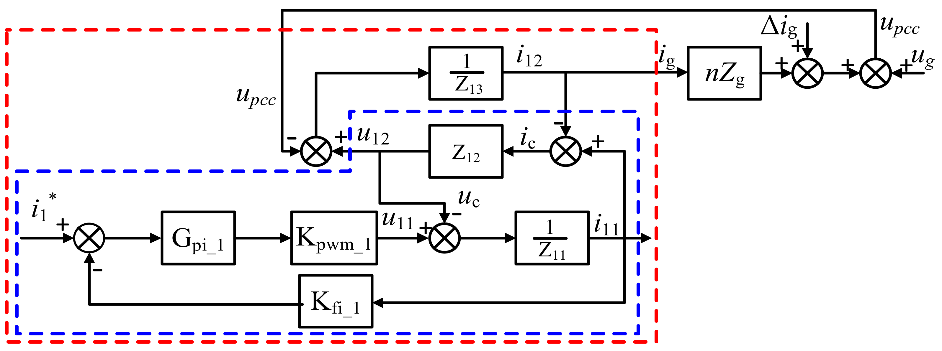
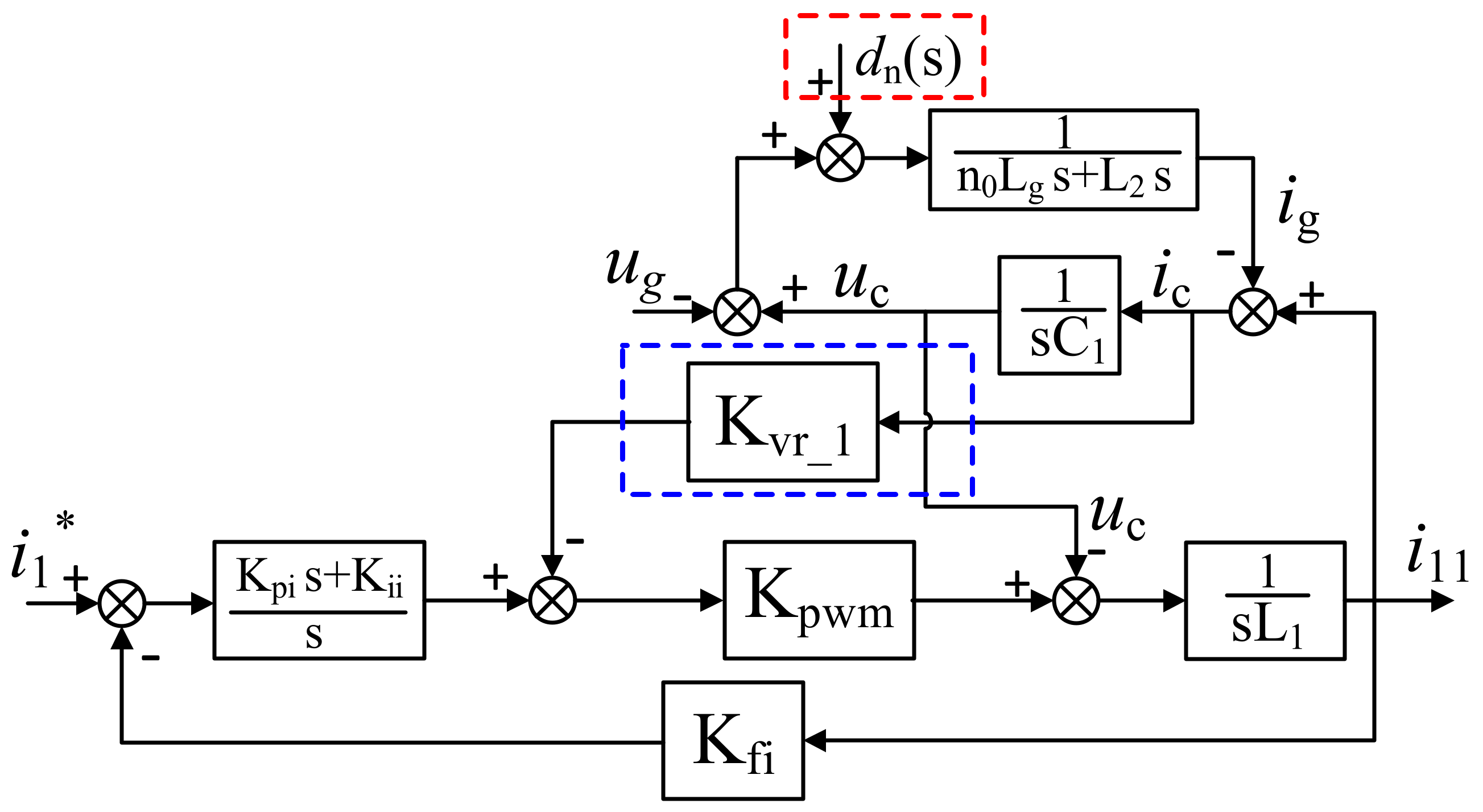
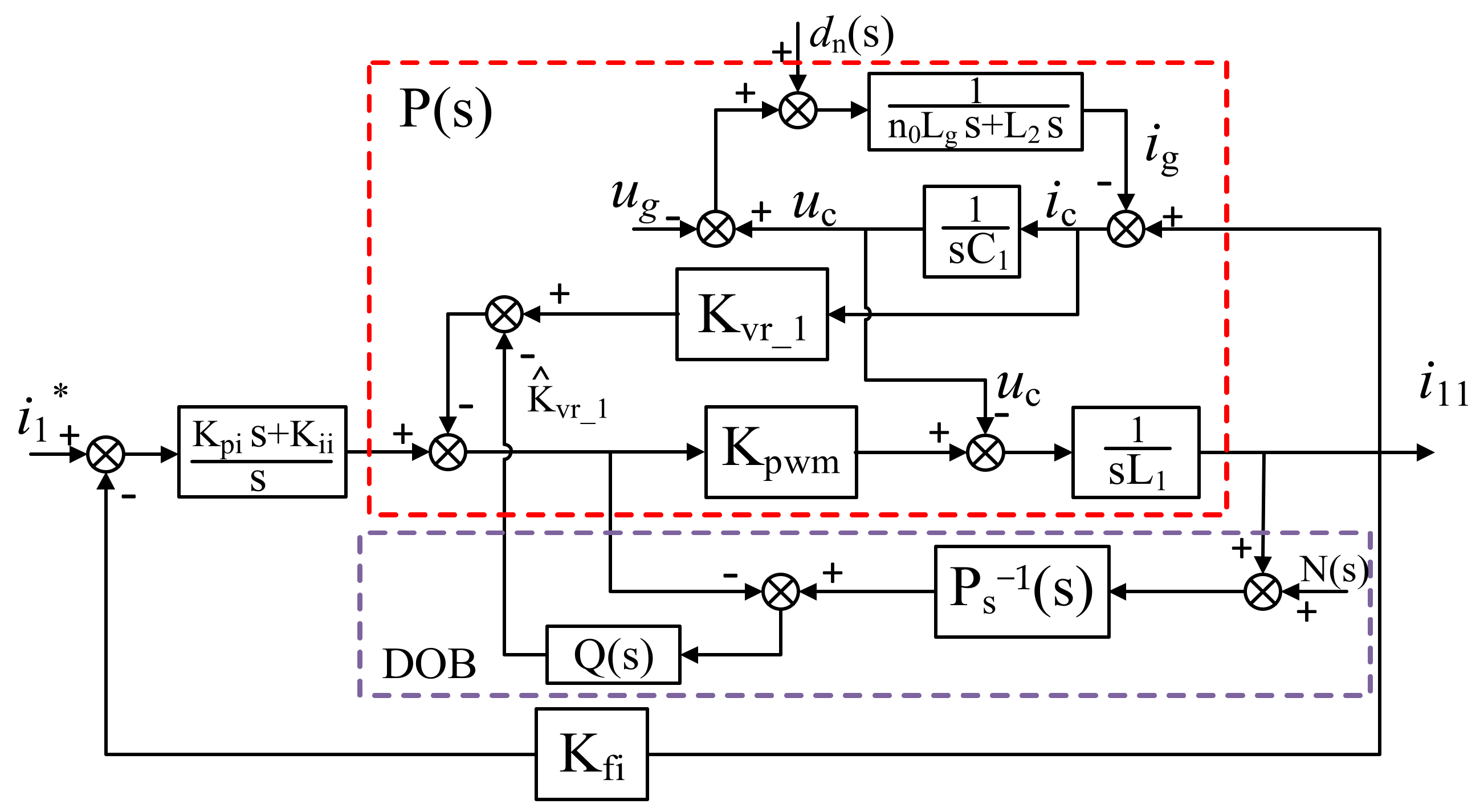
When the number of grid-connected units varies from 0 to 40, the virtual damping value needs to be dynamically adjusted to maintain a fixed damping ratio, which makes the design of the controller more complicated. To solve the above problems, we propose an active damping resonance suppression strategy based on a disturbance observer, the control block diagram of which is shown in Figure 10. In the method of active damping resonance suppression, a disturbance observer is added. When the number of grid-connected inverters varies between 0 and 40, changes in virtual impedance are observed by the disturbance observer, and a feedforward control is added to eliminate the influence of changes in virtual resistance on the grid-connected current.
The control system block diagram shown in 
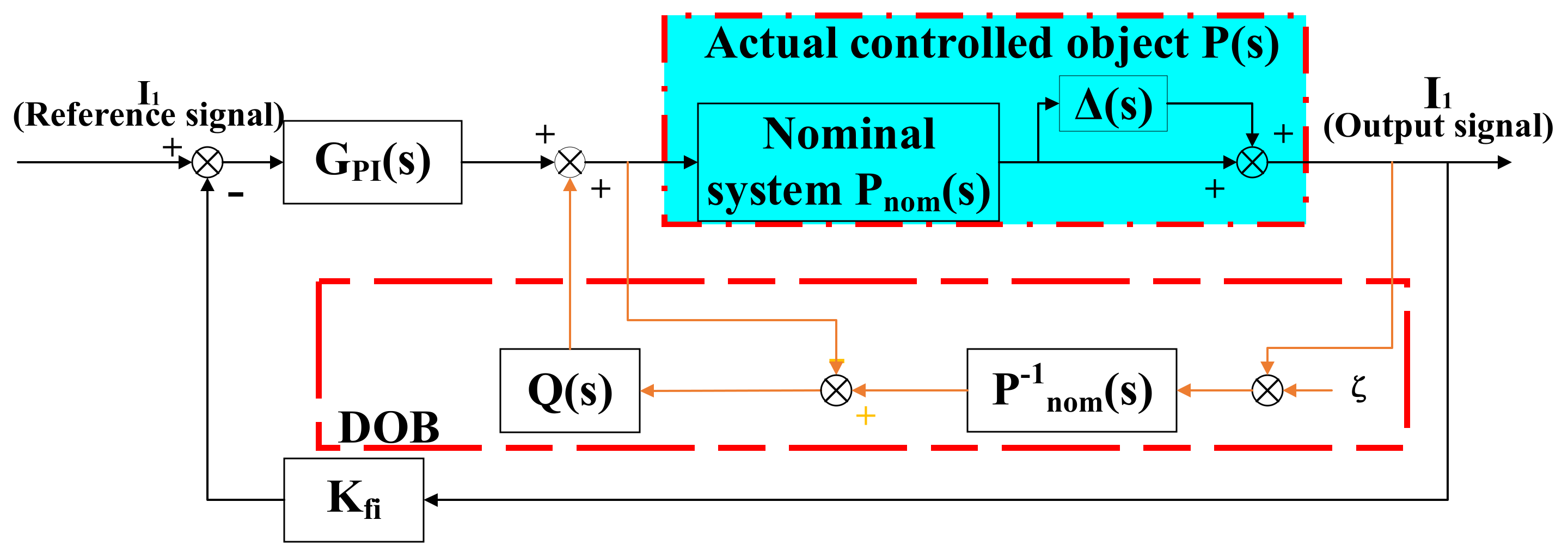
Figure 10 can be further simplified, as shown in Figure 11. GPI(s) is the PI controller, Q(s) is the low-pass filter to be designed, Kfi is the outer-ring proportional coefficient and ζ is the system used to measure high-frequency noise.
According to the equivalent control block diagram shown in Figure 11, the open-loop transfer function of the grid current (Ig(s))after adding a DOB is obtained as follows:
G o p e n ( s ) = k f i × G P I ( s ) × P ( s ) 1 P ( s ) × ( P n o m 1 ( s ) P 1 ( s ) ) × Q ( s ) = k f i × G P I × P ( s ) 1 ( P ( s ) × P n o m 1 ( s ) 1 ) × Q ( s ) = k f i × G P I × P n o m × ( 1 + Δ ( s ) ) 1 Δ ( s ) × Q ( s )
where:
Δ ( s ) = A 1 × s + A 2 ( B 1 × s 2 + B 2 × s + B 3 ) × ( B 4 × s 2 + 1 ) is the system disturbance set;
P n o m = k p w m Z 1 + G 1 ( s ) × G 2 ( s ) is the nominal controlled object;
P ( s ) = P n o m × ( 1 + Δ ( s ) ) is the actual controlled object with parameter perturbation;
G P I ( s ) = k p s + k i s ;
Z 1 = s L 1 , Z 2 = s C 1 , Z 3 = n 0 L g s + L 2 s ; G 1 ( s ) = 1 Z 2 + k v r _ 1 × k p w m ; G 2 ( s ) = Z 2 × Z 3 1 + Z 2 × Z 3 ; P n o m 1 ( s ) = 1 P n o m ( s ) ; A 1 = 1 × k v r _ 1 × k p w m × C 1 × Δ n × L g , A 2 = 1 × Δ n × L g , B 1 = C 1 × L 1 ( ( n 0 + Δ n ) L g + L 2 ) , B 2 = C 1 × k v r _ 1 × k p w m × ( ( n 0 + Δ n ) L g + L 2 ) , B 3 = ( n 0 + Δ n ) L g + L 2 + L 1 , B 4 = C 1 × ( n 0 L g + L 2 ) .

4.2. Design of the Filter in the Disturbance Observer

The filter (Q(s)) of a traditional disturbance observer usually adopts a low-pass filter to filter out high-frequency noise. In order to obtain an accurate disturbance value and reduce the use of sensors, we propose the use of a Kalman filter to replace the traditional low-pass filter. The Kalman filtering algorithm is as follows.
The discrete state equation of the general system is expressed as:
x k = F x k 1 + B u k 1 + w k
z k = H x k + v k
The state equation of the filtering system is expressed as (5), where x k denotes the value of the state variable at time k; F is the state transition matrix of the system; the error covariance matrix of the state variable matrix ( x k ) is defined as P k ; B is the influence matrix of input u on state x; and w k represents the process noise of the filtering system, and its corresponding covariance matrix is Q. The observation equation of the filtering system is presented in (6), where z k is the measurement signal of the system at time k; H is the observation matrix; and v k is the measurement noise, and the corresponding covariance matrix is R. The filtering steps are summarized as follows:
(1)
First, the state variables and their error covariances should be initialized;
(2)
Then, the state variables and covariances need to be predicted:
x ^ k = x ^ k 1
P k = P k 1 + Q
(3)
Then, the current state and covariance are updated by iteration;
K k = P k ( P k + R ) 1
x ^ k = x ^ k + K k ( z k x ^ k )
P k = ( I K k ) P k
P k 1 = E [ ( x k 1 x ^ k ) ( x k 1 x ^ k ) T ]
where x ^ k is the optimal estimation at the previous moment, P k is the error covariance at the previous moment, K k is the Kalman gain coefficient and x ^ k is the optimal estimation at the current moment.
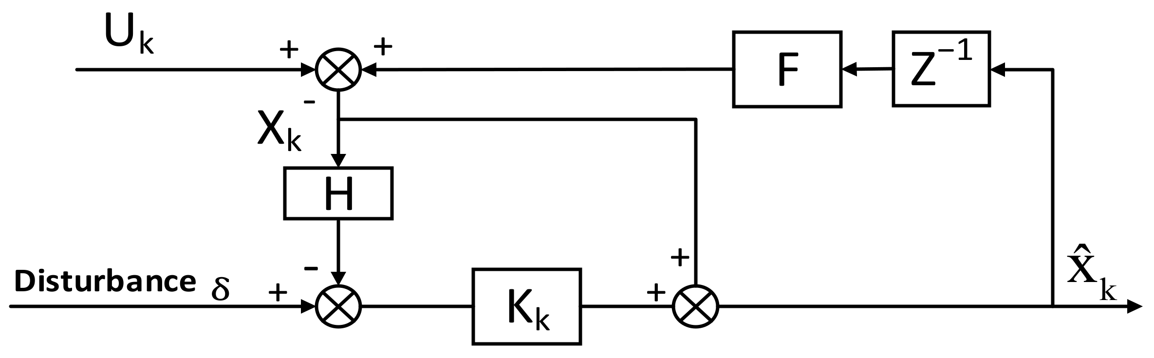
For further understanding, the equivalent control block diagram is shown in Figure 12 after being combined with the specific state variables. Then, the discrete transfer function of the Kalman filter module can be expressed as follows:
Q δ _ x ( z ) = z × ( z × I F K k × H × F ) 1 × K k

4.3. The Comparison of Virtual Damping before and after Adding the Proposed Disturbance Observer

Based on the approximate continuous discrete transfer function of the Kalman filter obtained in Section 4.2, the corresponding s-domain transfer function is acquired as follows:
Q δ _ x ( s ) = T s × K k ln ( 1 K k ) + T s × s
By introducing it into (4) and combining with the specific parameters in Table 1, the overall open-loop transfer function of the system can be obtained so that the virtual damping expression after adding the disturbance observer can be derived. At a damping ratio of 0.707, compared with the control strategy without a disturbance observer, the variation of the virtual damping is shown in Figure 13.
Figure 13a,b shows the virtual damping graphs before and after adding the proposed disturbance observer, respectively. Figure 13c,d shows the local amplification graphs of the virtual damping when the number of grid-connected inverters varies from 0 to 80. Figure 13c shows that the change rate of virtual damping without a disturbance observer is 0.16, and Figure 13d shows that the change rate of virtual damping with an improved disturbance observer is 0.025. Therefore, adding the improved DOB enables more accurate determination of the size of virtual damping, so the damping ratio of the system remains at 0.707 to improve the stability and robustness of the system.

5. Experiment

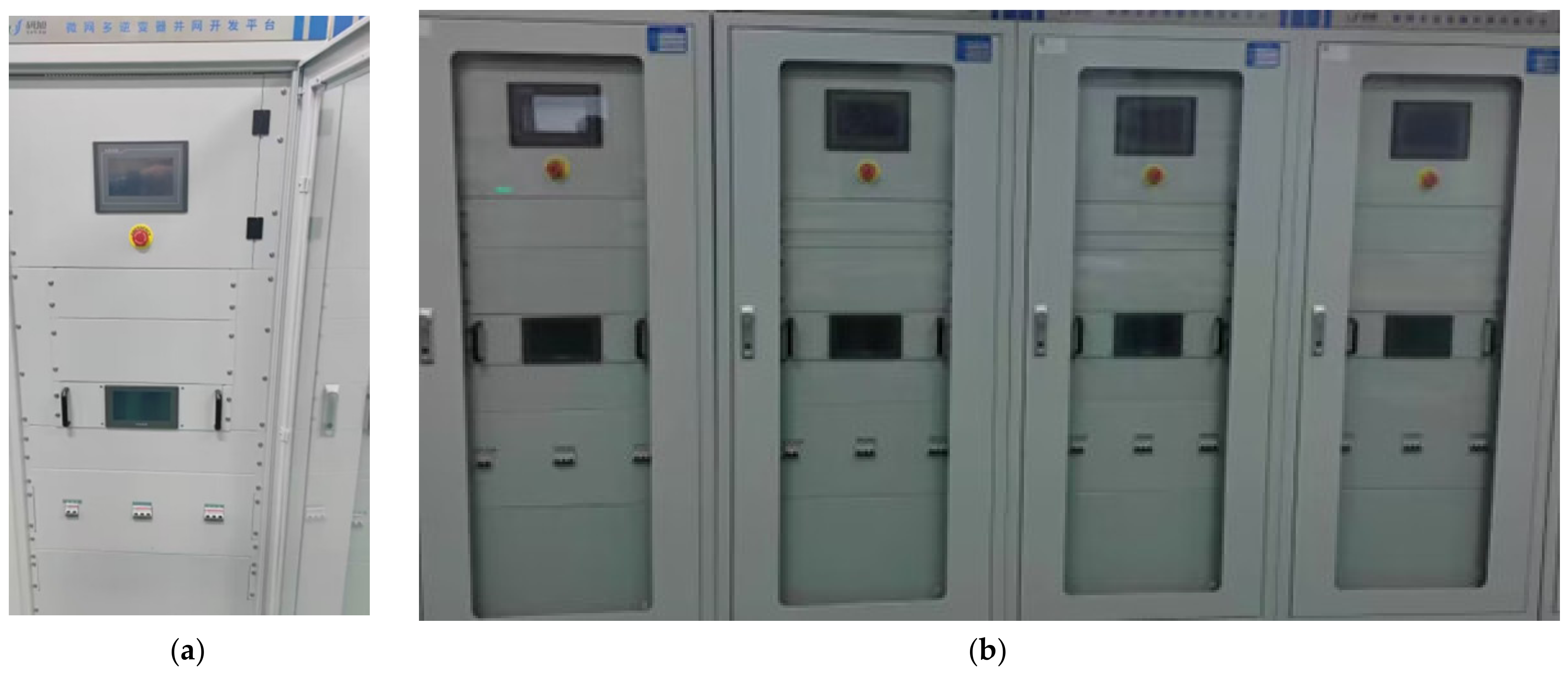
The parameters of the 200 MW photovoltaic cluster inverter studied in this paper are shown in Table 1, and a photo of prototype is shown in Figure 14.
Figure 15a,c shows the three-phase current waveforms of the grid when the 200 MW photovoltaic cluster inverter is in a steady state with and without the proposed controller. Figure 15b,d shows the corresponding local Zoom1 and Zoom2 waveforms, respectively. As shown in Figure 15b,d, when the proposed controller is utilized, the harmonic component of the grid current is significantly lower than that without the proposed controller. Therefore, the proposed controller can solve the problem of the large harmonic component of the grid current caused by grid-connected resonance.
Figure 16a,b shows the three-phase grid-connected current waveforms of a 200 MW PV cluster inverter without the proposed DOB when grid-connected resonance occurs from stable to dynamic increase in the number of parallel inverters. As shown in Figure 16b, when t = 1.2 s, with an increase in the number of parallel inverters, the harmonic component of the grid-connected current begins to increase gradually, indicating that the traditional fixed virtual damping control method cannot cope with the disturbance caused by the change in the number of parallel inverters.
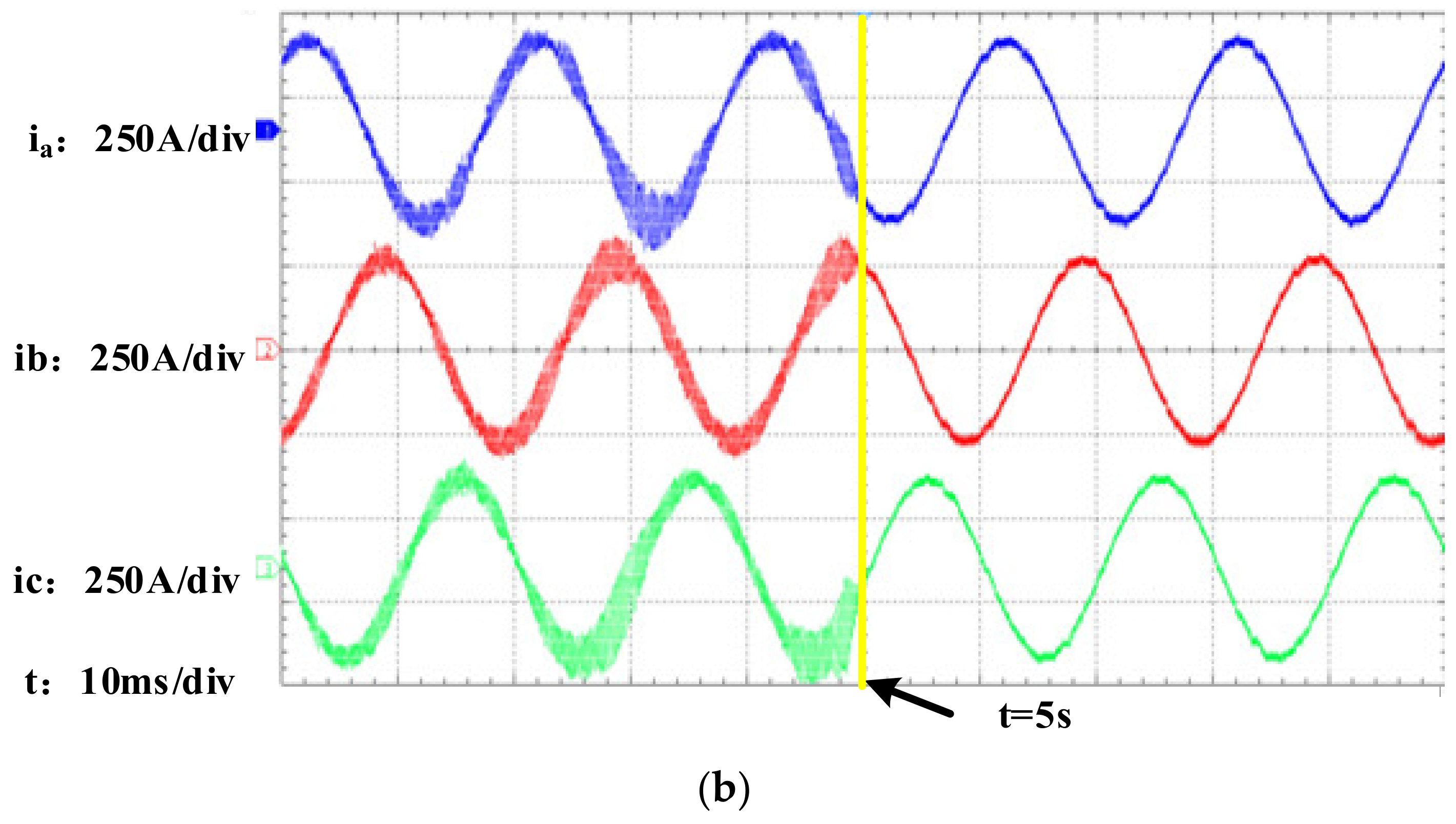
Figure 17a,b shows the three-phase grid-connected current waveforms from grid-connected resonance to dynamic stability when the number of parallel inverters is dynamically increased by 200 MW PV cluster inverters. As shown in Figure 17b, when the traditional fixed virtual damping control strategy is replaced by the proposed control strategy at t = 5 s, the virtual damping in the controller can be automatically adjusted according to the magnitude of the disturbance caused by the change in the number of parallel inverters, thereby suppressing the cluster resonance caused by the change in the number of parallel inverters and reducing the harmonic component of the grid-connected current.

6. Conclusions

In this paper, in response to the problem of grid-connected resonance of the cluster inverter in a 200 MW large photovoltaic power station, a corresponding equivalent mathematical model was established based on the actual parameters of the inverter, distribution transformer and grid impedance of the power station, and the relationship between the damping coefficient of the inverter and the dynamic number of grid-connected inverters was derived based on the mathematical model. Then, an active damping suppression strategy based on the improved disturbance observer was utilized to suppress the resonance of the photovoltaic cluster inverter. When the dynamic change in the number of grid-connected stations leads to a change in the virtual damping coefficient, the disturbance observer can dynamically observe the disturbance in the system and compensate for the change of the damping coefficient through the feedforward control so as to eliminate the influence of the damping coefficient on the photovoltaic power station in the dynamic operation of the cluster inverter. The measured results of the 200 MW photovoltaic power station verify that the proposed control strategy can effectively suppress the cluster resonance of a photovoltaic grid-connected inverter and improve the robustness of the system.

Author Contributions

Conceptualization, G.H. and Z.Z.; methodology, G.H. and Z.Z.; software, G.H., Z.Z. and J.L.; validation, Z.Z. and J.L.; formal analysis, G.H. and Z.Z.; investigation, C.Y.; resources, G.H.; data curation, G.H. and Z.Z.; writing—original draft preparation, G.H. and Z.Z.; writing—review and editing, G.H. and Z.Z.; visualization, G.L.; supervision, G.H.; project administration, G.H.; funding acquisition, G.H. All authors have read and agreed to the published version of the manuscript.

Funding

This research was funded by the Natural Science Foundation of Henan Province (222300420400).

Data Availability Statement

The data presented in this research study are available in this article.

Conflicts of Interest

The authors declare no conflict of interest.

Nomenclature

nNumber of grid-connected inverters
G le q _ n ( s ) Open-loop transfer function of the equivalent grid-connected current
G e q _ n ( v r ) ( s ) Open-loop transfer function of active damping with capacitor current feedback
k v r _ 1 Virtual damping
ξ v r Damping coefficient
DOBDisturbance observe
G o p e n ( s ) Open-loop transfer function of grid-connected current after adding a DOB
Q(s)Low-pass filter
Δ(s)System disturbance set
P ( s ) Actual controlled object with parameter perturbation
P n o m ( s ) Nominal controlled object
x k , u k State-variable vector and control input vector
F,B,HState transition, input and observation matrix
P k , P k Priori and posteriori covariance matrices
K k Kalman gain coefficient
w k , v k System noise and measurement noise covariance matrix
Q δ _ x ( z ) Discrete transfer function of the Kalman filter module
IIdentity matrix
T s Sampling time

References

  1. Zhang, X.; Yu, C.; Liu, F.; Li, F.; Xu, H.; Wang, Y.; Ni, H. Parallel Modeling and Resonance Analysis of Photovoltaic Grid-connected Multi-inverters. Proc. CSEE 2014, 34, 336–345. [Google Scholar] [CrossRef]
  2. Pan, D.; Ruan, X.; Wang, X.; Bao, C.; Li, W. Design of control parameters to enhance the robustness of LCL grid-connected inverter to power grid impedance. Proc. CSEE 2015, 35, 2558–2566. [Google Scholar] [CrossRef]
  3. Zeng, Z.; Xu, S.; Ran, L.; Chen, M. Active damper and control applied to resonance suppression of AC microgrid. Electr. Power Autom. Equip. 2016, 36, 15–20. [Google Scholar] [CrossRef]
  4. Wang, Y.; Liu, S.; Liu, J.; Wang, J. Research on resonance mechanism and damping control strategy of inverter grid-connected system. Proc. CSEE 2020, 40, 3008–3021. [Google Scholar] [CrossRef]
  5. Xie, Z.; Chen, Y.; Wu, W.; Wang, X.; Wang, Z. Global high-frequency oscillation suppression method of multi-inverter grid-connected system under weak power grid. Trans. China Electrotech. Soc. 2020, 35, 885–895. [Google Scholar] [CrossRef]
  6. Yu, H.; Su, J.; Zheng, L.; Zhang, T.; Zhang, D.; Shi, Y. Mechanism analysis and suppression method of sub -synchronous reso-nance for energy storage inverter connecting to power grid. Autom. Electr. Power Syst. 2020, 44, 99–108. [Google Scholar]
  7. Bian, Z.; He, Y.; Wu, Y.; Hang, L.; Lin, W. A grid-side current control strategy to improve the passivity and immunity of LCL grid-connected inverter. Proc. CSEE 2022, 42, 2175–2186. [Google Scholar] [CrossRef]
  8. Yang, M.; Zhou, L.; Zhang, D.; Zhang, M. Stability analysis of large-scale photovoltaic power plants for the effect of grid impedance. Trans. China Electrotech. Soc. 2013, 28, 214–223. [Google Scholar] [CrossRef]
  9. Zhou, L.; Zhang, M. Analysis of resonance phenomenon in large-scale photovoltaic power plant. Electr. Power Autom. Equip. 2014, 34, 8–14. [Google Scholar]
  10. Xu, D.; Wang, F.; Mao, H.; Ruan, Y.; Zhang, W. Modeling and analysis of harmonic interaction between multiple grid-connected inverters and the utility grid. Proc. CSEE 2013, 33, 64–71. [Google Scholar] [CrossRef]
  11. Yan, G.; Chang, Q.; Huang, Y.; Li, L.; Yu, Y. Analysis on parallel operational characteristics of multi photovoltaic inverters connected to weak-structured power system. Power Syst. Technol. 2014, 38, 933–940. [Google Scholar] [CrossRef]
  12. Sun, Z.; Yang, Z.; Wang, Y.; Xu, H. The cause analysis and suppression method of resonances in clustered grid-connected photovoltaic inverters. Proc. CSEE 2015, 35, 418–425. [Google Scholar] [CrossRef]
  13. He, G.; Xu, D. Multi-inverter grid-connected resonance suppression based on active damping. Electr. Mach. Control 2017, 21, 62–68. [Google Scholar] [CrossRef]
  14. Flota-Bañuelos, M.; Miranda-Vidales, H.; Fernández, B.; Ricalde, L.J.; Basam, A.; Medina, J. Harmonic Compensation via Grid-Tied Three-Phase Inverter with Variable Structure I&I Observer-Based Control Scheme. Energies 2022, 15, 6419. [Google Scholar]
  15. Rehman, A.U.; Ali, M.; Iqbal, S.; Shafiq, A.; Ullah, N.; Otaibi, S.A. Artificial Intelligence-Based Control and Coordination of Multiple PV Inverters for Reactive Power/Voltage Control of Power Distribution Networks. Energies 2022, 15, 6297. [Google Scholar] [CrossRef]
  16. Ali, R.; O’Donnell, T. Analysis and Mitigation of Harmonic Resonances in Multi–Parallel Grid–Connected Inverters: A Review. Energies 2022, 15, 5438. [Google Scholar] [CrossRef]
  17. Tu, C.; Gao, J.; Zhao, J.; Zhang, Y.; Guo, Q. Analysis and design of grid-connected inverter impedance remodeling with fixed stability margin in weak grid. Trans. China Electrotech. Soc. 2020, 35, 1327–1335. [Google Scholar] [CrossRef]
Figure 1. Structural diagram of the investigated 200 MW photovoltaic station.
Energies 15 07942 g001
Figure 2. Structural diagram of bus section I of the investigated 200 MW photovoltaic station.
Energies 15 07942 g002
Figure 3. Structural diagram of inverter cluster 1.1.
Energies 15 07942 g003
Figure 4. Equivalent circuit diagram of the 200 MW photovoltaic power station.
Energies 15 07942 g004
Figure 5. Equivalent schematic diagram of a single inverter.
Energies 15 07942 g005
Figure 6. Equivalent block diagram of a single inverter when multiple inverters are connected to the grid.
Energies 15 07942 g006
Figure 7. Open-loop Bode plot of multiple inverters.
Energies 15 07942 g007
Figure 8. Equivalent control block diagram of a single inverter when multiple inverters are connected to the grid.
Energies 15 07942 g008
Figure 9. Curve of virtue resistance relative to the number of grid-connected inverters (n).
Energies 15 07942 g009
Figure 10. Control block diagram of the active damping resonance suppression strategy based on a disturbance observer.
Energies 15 07942 g010
Figure 11. Equivalent control block diagram based on a disturbance observer.
Energies 15 07942 g011
Figure 12. Structure of the Kalman filter.
Energies 15 07942 g012
Figure 13. Virtual damping comparison without DOB; (a) virtual damping figure without DOB; (b) virtual damping figure with DOB; (c) partial enlarged view; (d) Partial enlarged view after adding the DOB.
Energies 15 07942 g013aEnergies 15 07942 g013b
Figure 14. Photo of the prototype. (a) Single inverter; (b) multiple inverters.
Energies 15 07942 g014
Figure 15. Grid current waveform during grid-connected resonance of the photovoltaic cluster inverter. (a) Without the proposed DOB; (b) the waveforms of Zoom 1; (c) with the proposed DOB; (d) the waveforms of Zoom 2.
Energies 15 07942 g015aEnergies 15 07942 g015b
Figure 16. Photovoltaic cluster inverter from stable to dynamic resonant grid current waveform. (a) Without the proposed DOB; (b) the waveforms of Zoom 1.
Energies 15 07942 g016aEnergies 15 07942 g016b
Figure 17. Photovoltaic cluster inverter from resonance to dynamic stable grid current waveform. (a) Replacing traditional controller with the proposed DOB at t = 5 s; (b) the waveforms of Zoom 1.
Energies 15 07942 g017aEnergies 15 07942 g017b
Table 1. Basic parameter of the investigates 500 kW inverter.
ParameterValue
Rated line voltage (UAB)315 V
Switching frequency (f)3 kHz
Dc-link capacitor (Cdc)15 µF
Inverter-side inductance (L1)0.23 mH
Grid-side inductance (L2)0.066 mH
Filter capacitor (C)400 µF
Equivalent grid impedance (Lg)0.015 mH
Publisher’s Note: MDPI stays neutral with regard to jurisdictional claims in published maps and institutional affiliations.

