Article

Analysis of the Thermal Processes in an Electromagnetic Mill

Faculty of Electrical Engineering, Czestochowa University of Technology, ul. J.H. Dąbrowskiego 69, 42-201 Częstochowa, Poland
Energies 2022, 15(21), 7899; https://doi.org/10.3390/en15217899
Submission received: 4 August 2022 / Revised: 8 October 2022 / Accepted: 21 October 2022 / Published: 25 October 2022
(This article belongs to the Special Issue Technical, Economic and Managerial Aspects of the Energy Transition)

Abstract

:
The purpose of this research is to develop effective methods for the thermal calculation of an electromagnetic mill. The article deals with the structural features of the liquid cooling system of such a device, with direct channel cooling of the induction coils. By analysing the recent research in this area, I have revealed that in order to achieve this goal it is expedient to use the finite element method (FEM). I have also suggested the input data for the boundary values to calculate a three-dimensional thermal field of an electromagnetic mill with an internal diameter of the working chamber of 200 mm. I have also graphically shown the results of calculating this problem using FEM analysis. Based on the analysis of the temperature field and gradient, I have also synthesized and substantiated the structure of the thermal equivalent circuit, which approximates the active part of the mill with a complex of five bodies with internal heat release and enables an approximate estimation of its thermal state at the initial stages of design to be held. I have suggested the formulae to calculate the parameters of this equivalent circuit and the principle to form a system of equations for the further determination of unknown temperatures. In addition, I have performed a comparative analysis of the methods for calculating the thermal state.

1. Introduction

An electromagnetic mill (EMM) is the technological equipment for the grinding or mixing of various compounds of nonaggressive or aggressive substances. It is also used to intensify various physical and chemical processes [1,2,3,4].
The challenges a designer of such a device faces are rather unusual for a specialist in electrical engineering or electrical machinery. In particular, one has to select values of the electromagnetic loads directly related to the thermal state of the mill without having the methods developed or having any recommendations or experience of the preliminary design. The maximum allowed current value in the inductor winding and the maximum value of the magnetic induction in the grinding area will depend on the efficiency of the cooling system. This is why EMM thermal state analysis is very important, allowing for an estimation of its parameters and serves as an objective indicator of the efficiency, reliability, cost effectiveness and competitiveness of an EMM.

2. Analysis of Recent Research

A typical solution to the problem of evaluating the thermal state of electrical equipment is the use of a thermal equivalent circuit (TEC), which is sometimes quite complex and extended [5,6] and is called a ‘thermal network’. Such equivalent circuits promote the mnemonic setting down of a system of equations, the solution of which is the excess of the temperature in the active elements of the above equipment. The concentrated parameters of these TEC are calculated on the basis of the classical theory of heat transfer [7,8]. However, the calculations are burdened by a number of challenges, with one of them being the determination of the integral coefficients of the heat conductivity of multicomponent structures [9,10].
An analytical or empirical study of the local temperatures of a facility is usually accompanied by comparison and verification with the results of an FEM analysis [11,12,13,14,15]. Therefore, it can be argued that the best tool for designing and substantiating the structure of the TEC of a cooling system are special mathematical models designed to solve the heat equation in a two- or three-dimensional setting.
One of the objectives of our research is to develop such a TEC structure which complies with the cooling system suggested, fully takes into account the main ways of heat transfer, and on the other hand, contains a minimum number of elements.
Liquid cooling systems have been successfully used by designers [11,16]. In addition in [6], special attention is paid to improved cooling achieved by the impregnation of the overhangs with a special heat-conducting compound.
Another part of thermal analysis is the task of formulating the boundary condition for further temperature field calculations. This condition determines the divergence between the calculated results and those acquired through the experiment. For the vast majority of practical applications, it is a Cauchy condition depending on the coefficients of heat transfer. In engineering practice, the coefficients of the heat transfer of real systems are usually determined by empirical formulae obtained on the basis of processing experimental data and using the mathematical methods of the theory of similarity [17].
The designing process and the analysis of thermal processes in the direct-drive gearless ball mill were given in [18]. The drive of such a mill is a module-combined motor with permanent magnets on a rotor. In order to cool particular segments in the stator core and in some of the windings which are placed in its grooves, a ‘cooling jacket’ is fixed on the outer surface of those magnets. The ‘cooling jacket’ consists of separate modules which are interconnected by cooling channels. The proposed method of cooling is characterised by a lower efficiency in comparison with the direct cooling of the induction coils. The method additionally requires a considerably bigger size of the active part of the mill to enable the installation of a modular cooling system.
In paper [19], the temperature field of the electromagnetic mill is measured by a thermal imagining camera. Taking into account the analysis of the obtained results, a model to measure the temperatures of the most intensely heated parts was made. The model was based on the concept of the thermal equivalent circuit. Unfortunately, no equations to calculate the parameters of this scheme were included in the article.
In a widely performed overview of the literature, no reference was found regarding studies on the analysis of cooling inductor systems in electromagnetic mills with direct liquid-based cooling of windings powered by an electric current.

3. Structure of the Cooling System

The EMM consists of a magnetic field inductor with an independent cooling system and a working chamber containing small ferromagnetic cylinders (millstones). The inductor, in turn, consists of a sheet core, a frame and a three-phase winding. It is connected to an industrial three-phase network of alternating current and creates a rotating magnetic field in the working chamber which makes the millstones move and interact with the material (grinded or mixed).
Based on the results of our previous studies, we found that the current density in the inductor winding should be greater than 10 A/mm2, with the average magnetic induction in the working chamber of 0.1 T. Thus, we suggest using an autonomous convection system of forced channel liquid cooling of the closed type. Heat is transferred through the active and structural elements of the mill to a liquid coolant, which passes through the channels of the coils of the inductor.
Liquid coolant, for example, deionized water, various antifreeze agents, oil, etc., subjected to the pressure created by an electric pump, enters the inlet collector (1) of the EMM inductor (Figure 1). Then, it gets through many parallel paths to the winding coil channels (3). By drawing heat losses from the middle of each coil, the heated coolant enters the outlet collector (2), and then, as an option, it enters the radiator with its own independent cooling system.
The copper conductor, from which the inductor coils are made, is a hollow rectangular tube. The cavity in the middle of the conductor forms a spiral channel through which the coolant passes.
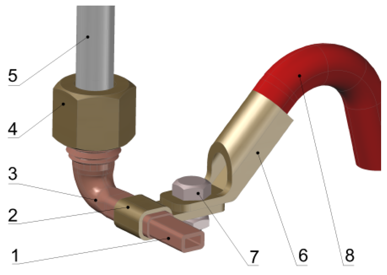
Special fittings (4) are used to tightly join the tubular conductors of the winding to the plastic pipeline connecting them to collectors (1) and (2). At the same time, they provide the current lead to the coils and connect them together (5), in accordance with the electrical circuit. The detailed design of the fitting is shown in Figure 2.
A capacitor is used to compensate for the EMM reactive power consumed. If it is necessary to use liquid-filled capacitors, the design of the cooling system suggested enables simultaneous cooling of the inductor, capacitor and conductors (5) (Figure 1), connecting the winding of the inductor and capacitors. To do this, it is sufficient to install an additional collector (6), which directs the cooling liquid into the channels of these conductors and along them to the ‘cooling jacket’ of the capacitors.
Efficient cooling will reduce the outer diameter of the mill core, thereby solving the problem of the excessive scattering of magnetic flux, which occurs in available structures [1], as well as the reactive component of phase currents and overall power consumption.

4. Numerical Analysis

To calculate the stationary field of the EMM temperature, which corresponds to the cooling method suggested (Figure 1), a mathematical model has been created based on three-dimensional FEM analysis.
This model is founded on the following assumption: the sheet core of the model inductor is considered as a homogeneous body, which follows the shape of the real core of the inductor, with different equivalent coefficients of the thermal conductivity in the orthogonal directions of heat transfer. The equivalent coefficients of the model inductor are equal to the coefficients of the thermal conductivity of the real core of the inductor in orthogonal directions.
The coefficients of the heat transfer of this system are determined by the formulae obtained using the theory of similarity [17].
Input data used to create the model are the power losses, the coefficients of the thermal conductivity of materials and structural elements of the mill, and the dimensions, structural parameters and boundary conditions in the form of the coefficients of the heat transfer from the surfaces of cooling. It should be noted that the losses in the inductor coil are calculated taking into account the skin effect [20]. All these data are shown in Table 1.

5. Research Methods

The mathematical formulation of the problem is based on the thermal conductivity equation for a stationary temperature field. In Cartesian coordinate system:
λ x 2 T x 2 + λ y 2 T y 2 + λ z 2 T z 2 + p v = 0
where λx, λy and λz are the constant coefficients of thermal conductivity of the environment in the direction of the axes of the coordinate system; and pv is intensity of internal heat emission per unit of the volume, W/m3.
In addition, we consider the boundary condition of Dirichlet and Cauchy as prescribed at the boundary of the computational region:
T L = ξ ( x , y , z ) ;         λ T L n ¯ + α ( T L T 0 ) + ζ ( x , y , z ) = 0 ,
where n ¯ is normal to the boundary of the computational region; α is coefficient of heat transfer; ξ(x,y,z) and ς(x,y,z) are undefined functions of the point position; and Tz and T0 are, respectively, temperature at area bound and absolute environment temperature.
Equation (1), along with the boundary condition (2), form the content of the mathematical formulation of the boundary value of calculating a stationary temperature field in an arbitrary shape body.
Symmetrical distribution of the temperature in the cross-section of the EMM inductor makes it possible to construct only 1/Z of the computational region, where Z is the number of claws of the inductor. Its surfaces, which belong to the symmetry planes, are adiabatic. The heat dissipation occurs only from the surface generators of the frame, the working chamber and the cooling system channels.
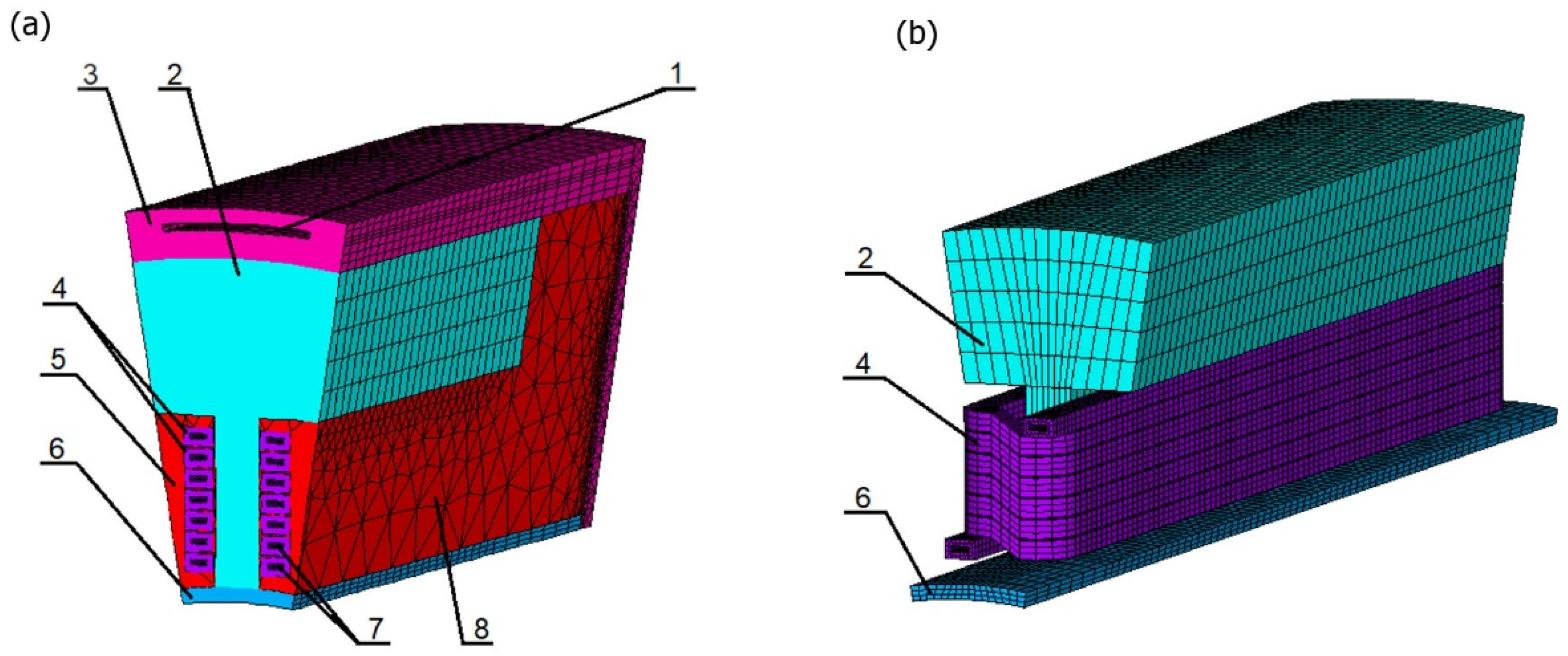
In order to expand the functional possibilities of the model, its program implementation involves not only parameterizing all dimensions and winding data of the inductor but also different designs of cooling systems. To this end, there are axial channels between the inductors and the core (Figure 3).
This technique enables the analysis of several typical methods of cooling the inductor, changing only the dimensions of these channels, their number and the value of the coefficient of the heat transfer from their surface, for example, such as a frame with an internal channel cooling (liquid or air) or a finned or smooth frame for forced or natural cooling.
The tooth of the inductor core in the finite element model has parallel walls, in contrast to the real inductor of the mill. This somewhat simplifies the geometry of the multiturn coil with an internal channel, which reduces the likelihood of degeneration of finite elements of the model.

6. Results and Discussion

The analysis of the simulation results reveals the most probable ways of distributing the heat flow from all of the heat-generating parts of the EMM. The results can also help develop the structure of the TEC, which when subjected to the one-dimensional nature of the heat flow would enable the determination of the average values of temperatures. The determination of the average values in these areas would be possible with only minimal error relative to their valid physical values.
Figure 3a shows a general view of a finite elemental model of 1/6 of the EMM with an internal diameter of the working chamber of 200 mm (total number of nodes: 107,289; number of elements: 196,311). Figure 3b shows its active area (an inductor with a coil). The model was developed according to the dimensions indicated in Table 1.
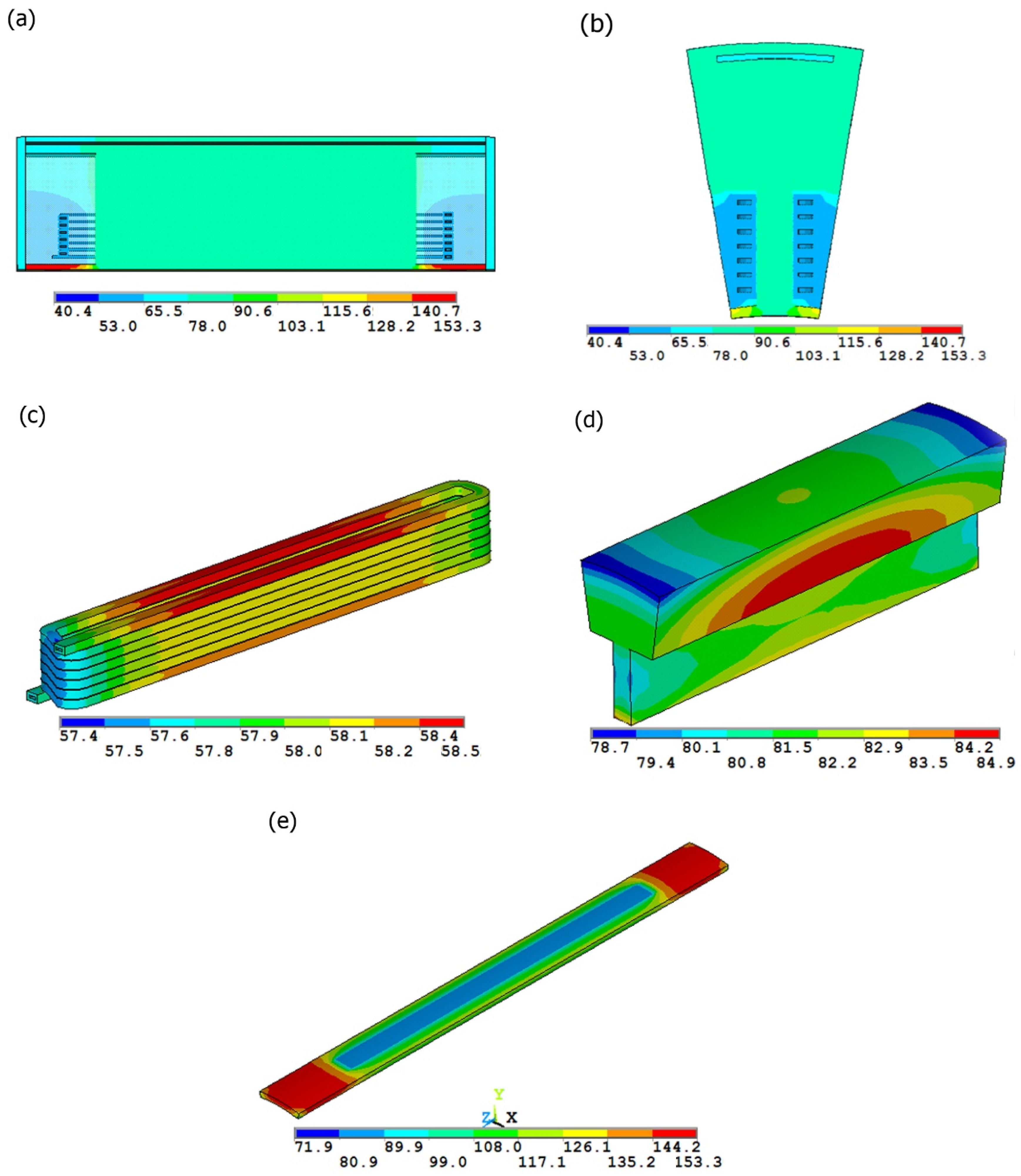
Figure 4a–e show the distribution of the temperature field in the main sections of the EMM and its active parts in the form of raster images.
As the figures show, the temperature field is symmetrical with respect to the planes of the longitudinal and transverse sections of the magnetic circuit of the EMM. The highest temperature gradient is observed in the areas of the thermal contact of the wall of the working chamber with the claw of the inductor core. In addition, the temperature distribution indicates a relatively weak influence of the sources of heat in the core of the inductor on the winding temperature and vice versa.
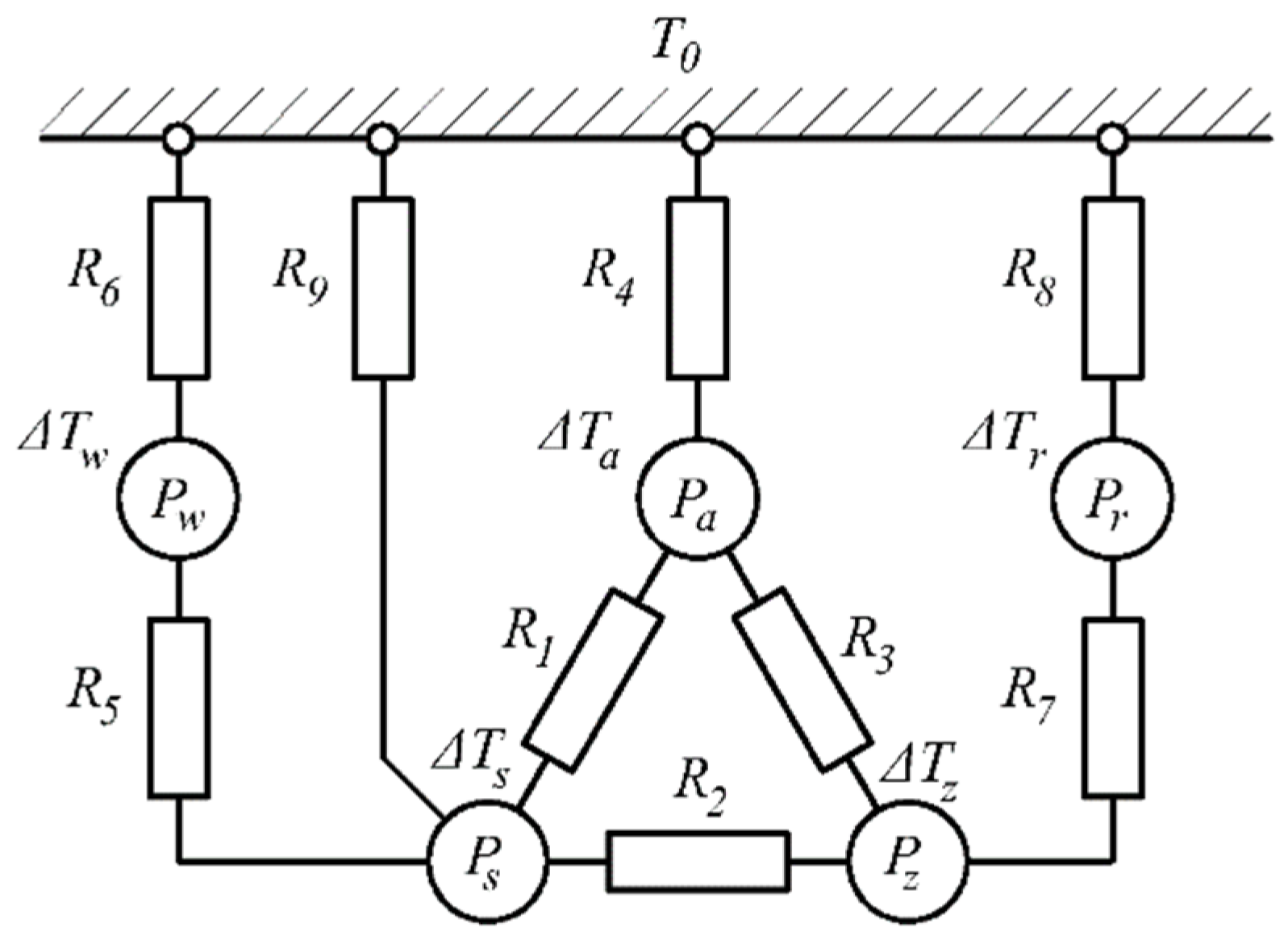
It is possible to indirectly suggest the structure of the scheme shown in Figure 5 due to a comprehensive analysis of the temperature field and familiarization with the structures of the TEC of applicable general-purpose electric machines [21].
The mill inductor is considered to be a complex of five bodies in which heat is released. These bodies are interconnected by their respective thermal resistance.
The loss of power in the scheme is reflected using the symbols entered (see Table 1), and the excess of temperature of the corresponding parts of the mill in [K] is indicated as follows: ΔTs: of the slot of the inductor coil; ΔTw: of its overhang; ΔTz: of the inductor core claws; ΔTa: of the inductor core yoke; ΔTr: of the walls of the working chamber; and T0: the absolute temperature of the environment (coolant). The thermal resistance to the heat flow [K/W] is indicated as follows: R1: between the slot of the winding and the yoke of the inductor; R2: between the slot of the coil and the claws of the inductor; R3: between the claws and the yoke of the inductor; R4: between the inductor yoke, the frame and the environment; R5: between the slot and the overhang of the inductor coil; R6: between the overhang of the inductor coil, the internal filler (compound) and the environment; R7: between the inductors and the wall of the working chamber; R8: between the wall of the working chamber and the environment; and R9: between the slot of the inductor coil and the environment.
For a flat wall with an evenly distributed heat source within, in the Cartesian coordinate system and under the condition of uniform heat distribution, the formula is as follows:
d 2 T d x 2 = p v λ ,
where p v = P T V T are the specific losses resulting from the energy dispersion for each m3, W m 3 .
The solution of Equation (3) can be written as follows:
T = p v x 2 2 λ + C 1 x + C 2 ,
where C1 and C2 are the constants of integration, and x is the current x axis coordinate (Figure 6).
Assuming the following boundary condition, the temperature of the side walls is T = T1 for x = 0 and T = T2 for x = δ. In this case, the constants of integration will be defined as:
C 2 = T 1 ;         C 1 = p v δ 2 λ + T 2 T 1 δ
For that reason, the temperature distribution of a flat wall with a one-dimensional heat distribution characteristic is described as:
T = p v x 2 2 λ + ( p v δ 2 λ + T 2 T 1 δ ) x + T 1
In order to gauge the thermal state of different structural components of the EMM based on the TEC, we used temperature averages, namely:
T m = 1 δ 0 δ T d x = 1 δ [ p v 2 λ 0 δ x 2 d x + ( p v δ 2 λ + T 2 T 1 δ ) 0 δ x d x ] + T 1 = = p v δ 2 12 λ + T 1 + T 2 T 1 2 ,
or assuming that p v = P T δ S , where S is the side wall area,
T m = P T δ 2 12 S δ λ + T 1 + T 2 T 1 2 = P T R T 12 + T 1 + T 2 T 1 2
where
R T = δ λ S
is thermal resistance, which limits the heat flow through a flat wall.
In accordance with Fourier’s law and taking (6) into consideration, the heat stream through the wall is:
Q = λ S d T d x = p v S x p v δ S 2 λ S ( T 2 T 1 ) δ
Using the parameter RT allows for the calculation of the temperature difference in a wall under a lack of heat:
T 2 T 1 = R T Q
and allows the consideration of some of the structural elements of the EMM such as walls conducting heat without dissipation based on the replacement scheme (Figure 7a). For similar elements with internal heat generation, we used a replacement scheme (Figure 7b), for which:
R 1 = R 2 = R T / 2
In case of a cylindrical wall with a one-dimensional approximation of a temperature field, the formula for thermal conductivity can be written with a cylindrical coordinate system for convenience sake:
d d r ( r d T d r ) = p v r λ ,
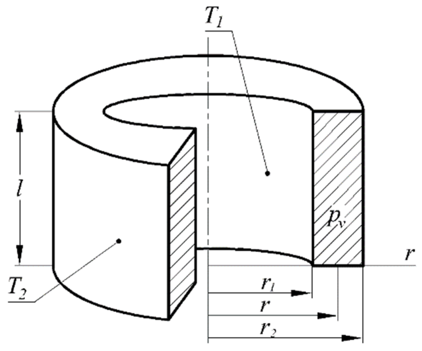
where r is the radial direction (Figure 8).
After two integrations of Equation (13), the general solution looks like (14):
T = p v r 2 4 λ + C 1 ln r + C 2
Under the boundary condition, the temperature on the inner and outer wall side is T = T1 with r = 0 and T = T2 with r = r2 (Figure 8). The full formula can be written as:
T = p v r 2 4 λ + 1 ln ( r 2 r 1 ) [ p v 4 λ ( r 2 2 ln ( r r 1 ) + r 1 2 ln ( r 2 r ) + T 2 ln ( r r 1 ) + T 1 ln ( r 2 r ) ) ]
The heat flow through a cylindrical wall is:
Q = λ S d T d r = 2 π r l λ d T d r = P T [ r 2 r 2 2 r 1 2 1 2 ln ( r 2 r 1 ) ] + ( T 1 T 2 ) 2 π   l λ ln ( r 2 r 1 )
where there is no heat (PT = 0), and Equation (16) can be written using the concept of thermal resistance:
Q = ( T 1 T 2 ) 2 π   l λ ln ( r 2 r 1 ) = T 1 T 2 R T
where
R T = ln ( r 2 r 1 ) 2 π   l λ
is the thermal resistance of a cylindrical wall for its use in a thermal equivalent circuit corresponding to Figure 7a. If the wall generates heat loss (Figure 7b), the TEC parameters are calculated as follows:
R 1 = R T [ r 2 2 r 2 2 r 1 2 1 2 ln ( r 2 r 1 ) ] ;         R 2 = R T [ 1 2 ln ( r 2 r 1 ) r 1 2 r 2 2 r 1 2 ] .
The average temperature can be calculated with the following formula:
T m = 1 V 0 δ T d V = 2 r 2 2 r 1 2 r 1 r 2 T r d r = = p v 8 λ [ ( r 2 2 + r 1 2 ) r 2 2 r 1 2 ln ( r 2 r 1 ) ] + T 1 [ 1 2 ln ( r 2 r 1 ) r 1 2 r 2 2 r 1 2 ] + T 2 [ r 2 2 r 2 2 r 1 2 1 2 ln ( r 2 r 1 ) ] ,
where
p v = P T π ( r 2 2 r 1 2 ) l
The formulae for calculating the resistance are obtained on the basis of analytical solutions of the heat equation in the one-dimensional case for heat conducting bodies with the simple form [17]:
R 1 = 0.5 h s z 12 λ e w r b s l 1 + ln ( D a / D a i ) 2 π   l 1 λ e a r b s + b s z b s [ D a 2 D a 2 D a i 2 0.5 ln ( D a / D a i ) ] ; R 2 = 0.5 b s 12 λ e w τ ( h s + b s ) l 1 + 0.5 b s z 12 λ e a r ( h s + b s ) l 1 ; R 3 = h s z 12 λ e a r b s z l 1 + Z ln ( D a / D a i ) 2 π   l 1 λ e a r b s + b s z b s z [ D a 2 D a 2 D a i 2 0.5 ln ( D a / D a i ) ] ; R 4 = Z ln ( D a / D a i ) 2 π   l 1 λ e a r [ 0.5 ln ( D a / D a i ) D a i 2 D a 2 D a i 2 ] + 1 α w 1 S c ; R 5 = 0.3 l Σ w o + 0.5 l 1 12 λ e w a b s h s ; R 6 = R 61 R 62 R 64 + R 61 R 63 R 64 + R 62 R 62 R 64 R 61 R 62 + R 61 R 63 + R 61 R 64 + R 62 R 63 + R 62 R 64 ,
where
R 61 = h s 12 λ e w r b s l Σ w o + 0.25 ( D a D 2 h s z ) Z 2 λ e a l w o π D a i ;
R 62 = b s 12 λ e w τ h s l Σ w o + 0.5 Z ( l b m l 1 t b r s ) l w o Z 2 λ e a h s π D a i ;
R 63 = l f r m α w 2 S c ( l f r m l 1 ) ;         R 64 = 1 α w 1 l Σ w o w c w P c w ;
R 7 = h s z 12 λ e a r b s z l 1 + Z ln ( D / D r ) 2 π   l 1 λ c m [ 0.5 ln ( D / D r ) D r 2 D 2 D r 2 ] ;
R 8 = Z ln ( D / D r ) 2 π   l 1 λ c m [ D 2 D 2 D r 2 0 . 5 ln ( D / D r ) ] + l f r m α w 3 S r k l 1 ;
R 9 = 1 α w 1 l 1 w c w P c w
To reduce the recording of the calculation formulae, the following geometric characteristics are introduced:
  • Dai: inside diameter of the inductor yoke;
  • Dr: inside diameter of the tube of the working chamber;
  • Pcw: perimeter of the channel in the coil conductor;
  • Piz: perimeter of the channel in the frame;
  • lΣwo: length of the overhang of the coil;
  • Sc: surface area of the frame cooling;
  • Srk: surface area of the working chamber cooling.
All these parameters can be easily calculated on the basis of the dimensions of Table 1 or after the detailed design of the mill.
The system of equations, the solution of which is the desired excess of temperature ΔTs, ΔTw, ΔTz, ΔTa and ΔTr, looks like this:
{ ( Λ 1 + Λ 2 + Λ 5 + Λ 9 ) Δ T s Λ 5 Δ T w Λ 2 Δ T z Λ 1 Δ T a = P s Λ 5 Δ T s + ( Λ 5 + Λ 6 ) Δ T w = P w Λ 2 Δ T s + ( Λ 2 + Λ 3 + Λ 7 ) Δ T z Λ 3 Δ T a Λ 7 Δ T r = P z Λ 1 Δ T s Λ 3 Δ T z + ( Λ 1 + Λ 3 + Λ 4 ) Δ T a = P a Λ 7 Δ T z + ( Λ 7 + Λ 8 ) Δ T r = P r
where Λ i = R i 1   ( i = 1 , 9 ¯ ) is the corresponding thermal conductivity of the TEC.
The absolute average values of the temperatures of the five bodies, which the mill is conditionally divided into, are determined as follows:
T = T 0 + Δ T
where Δ T = Δ T s Δ T w Δ T z Δ T a Δ T r are the vectors of the excess of temperature, and T = T s T w T z T a T r are the absolute temperature vectors.
The test task, solved by means of a three-dimensional field model and described at the beginning of this subsection, was solved for the second time on the basis of the description using the TEC suggested.
The thermal resistance, calculated according to the method (22) and based on the data in Table 1, is [K/W]: R1 = 3.185; R2 = 0.3594; R3 = 0.3110; R4 = 1.213; R5 = 0.06628; R6 = 0.006470; R7 = 1.193; R8 = 81.26; and R9 = 0.006847.
The overview of the results obtained on the basis of FEM analysis and TEC analysis have been presented in Table 2.

7. Conclusions

  • The replacement of the inductor core with a thermally anisotropic homogenous body reduces the size of the coefficient matrix for the calculation of the temperature field due to a significant reduction in the detail of the computational area. At the same time, the accuracy of the calculated temperature values is virtually unchanged.
  • The equivalent coefficients of thermal conductivity, assuming a one-dimensional heat distribution in the EMM, used for the calculation of the parameters of thermal-equivalent schemes, ensure the accurate calculation of the mean values of temperatures of the active parts at the level of 15–20% compared to the actual values.
  • Based on the comparative analysis of the results of the calculation of the mean values of the temperature of the EMM components with forced liquid cooling using the TEC and FEM analysis, it was revealed that the discrepancy in the results does not exceed 6%. This substantiates that the TEC structure selected adequately reflects the most probable ways of distributing heat flows. The methods for calculating thermal resistance based on analytical solutions of the heat conductivity equation provide satisfactory accuracy of the estimation of the EMM thermal state.
  • The system of forced double-circuit liquid cooling can provide effective heat removal from active parts, which makes it suitable for use in the EMM.

Funding

This research received no external funding.

Data Availability Statement

Author’s own data obtained from calculations performed by the author.

Conflicts of Interest

The author declare no conflict of interest.

References

  1. Wolosiewicz-Glab, M.; Foszcz, D.; Gawenda, T.; Ogonowski, S. Design of an electromagnetic mill. Its technological and control system structures for dry milling. E3s Web Conf. EDP Sci. 2016, 8, 1066. [Google Scholar] [CrossRef] [Green Version]
  2. Styła, S. Examination of an electromagnetic mill structure by means of infrared radiation. Prz. Elektrotech. 2014, 90, 179–182. [Google Scholar] [CrossRef]
  3. Całus, D.; Makarchuk, O. Analysis of interaction of forces of working elements in electromagnetic mill. Prz. Electrotech. 2019, 12, 64–69. [Google Scholar] [CrossRef]
  4. Makarchuk, O.; Calus, D. Reserch of the performance indicator of an electromagnetic mill. Tech. Electrodyn. (Tekhnichna Elektrodynamika) 2022, 1, 50–57. [Google Scholar] [CrossRef]
  5. Kolondzovski, Z.; Arkkio, A.; Larjola, J.; Sallinen, P. Power limits of high-speed permanent-magnet electrical machines for compressor applications. Rep. Ser. Electromechanics Aalto Univ. Sch. Sci. Technol. Espoo 2010, 76, 73–82. [Google Scholar] [CrossRef]
  6. Nategh, S. Thermal Analysis and Management of High-Performance Electrical Machines. Ph.D. Thesis, Department of Electrical Energy Conversion, KTH Royal Institute of Technology, Stockholm, Sweden, 2013; pp. 1–137. [Google Scholar]
  7. Kutateladze, S.S. Heat Transfer and Hydrodynamic Resistance: Reference Manual; Teploperedacha i gidrodinamicheskoye soprotivleniye: Spravochnoye posobiye; Kutateladze, S.S., Ed.; Energoatomizdat: Moskow, Russia, 1990; p. 367. (In Russian) [Google Scholar]
  8. Mikheev, M.A.; Mikheeva, I.M. Fundamentals of Heat Transfer, 2nd ed.; Energy: Moskow, Russia, 1977; pp. 1–344. (In Russian) [Google Scholar]
  9. Kolondzovski, Z. Thermal and Mechanical Analyses of High-Speed Permanentmagnet Electrical Machines. Ph.D. Thesis, Department of Electrical Engineering, Aalto University School of Science and Technology, Espoo, Finland, 2010; pp. 1–94. [Google Scholar]
  10. Staton, D.; Boglietti, A.; Cavagnino, A. Solving the more difficult aspects of electric motor thermal analysis. In Proceedings of the Electric Machines and Drives Conference, IEMDC’03. IEEE International, Madison, WI, USA, 1–4 June 2003; Volume 2, pp. 747–755. [Google Scholar]
  11. Makarchuk, O.; Lis, M.; Gastołek, A.; Sosnowski, J. Analiza stanu cieplnego wysokoobrotowych maszyn elektrycznych o wzbudzeniu od magnesów trwałych z chłodzeniem cieczowym. Zesz. Probl. Masz. Elektr. 2015, 1, 7–15. [Google Scholar]
  12. Huang, Y.; Zhu, J.; Guo, Y. Thermal Analysis of High-Speed SMC Motor Based on Thermal Network and 3-D FEA With Rotational Core Loss Included. Magn. IEEE Trans. 2009, 45, 4680–4683. [Google Scholar] [CrossRef] [Green Version]
  13. ANSYS, Inc. Theory Reference, ANSYS Release 9.0, ANSYS Inc Products, Southpointe, 275 Technology Drive, Canonsburg, PA, USA. November 2004. Available online: https://www.ansys.com (accessed on 3 August 2022).
  14. Guo, C.; Long, L.; Wu, Y.; Xu, K.; Ye, H. Electromagnetic-thermal coupling analysis of a permanent-magnet in-wheel motor with cooling channels in the deepened stator slots. Case Stud. Therm. Eng. 2022, 35, 102158. [Google Scholar] [CrossRef]
  15. Chen, B.; Guan, X.; Cai, D.; Li, H. Simulation on thermal characteristics of high-speed motorized spindle. Case Stud. Therm. Eng. 2022, 35, 102144. [Google Scholar] [CrossRef]
  16. Sim, K.; Lee, Y.B.; Jang, S.M.; Kim, T.H. Thermal analysis of high-speed permanent magnet motor with cooling flows supported on gas foil bearings: Part I-coupled thermal and loss modeling. J. Mech. Sci. Technol. 2015, 29, 5469–5476. [Google Scholar] [CrossRef]
  17. Kreith, F.; Black, W.Z. Basic Heat Transfer; Harper & Row: New York, NY, USA, 1980; pp. 1–259. [Google Scholar]
  18. Xu, Y.; Zhang, B.; Feng, G. Electromagnetic design and thermal analysis of module combined permanent magnet motor with wrapped type for mine ball mill. IET Electr. Power Appl. 2022, 16, 139–157. [Google Scholar] [CrossRef]
  19. Styła, S. Analysis of temperature distribution in electromagnetic mill. Prz. Elektrotech. 2016, 92, 103–106. [Google Scholar] [CrossRef]
  20. Makarchuk, O.V. Additional losses in the stator windinds of the high-speed brushless electrical machine with the permanent magnets. Sci. Bull. Natl. Min. Univ. 2016, 6, 107–113. [Google Scholar]
  21. Borisenko, A.I.; Kostikov, O.N.; Yakovlev, L.I. Cooling of Industrial Electric Machines; Energoatomizdat: Moskow, Russia, 1983; pp. 1–296. (In Russian) [Google Scholar]
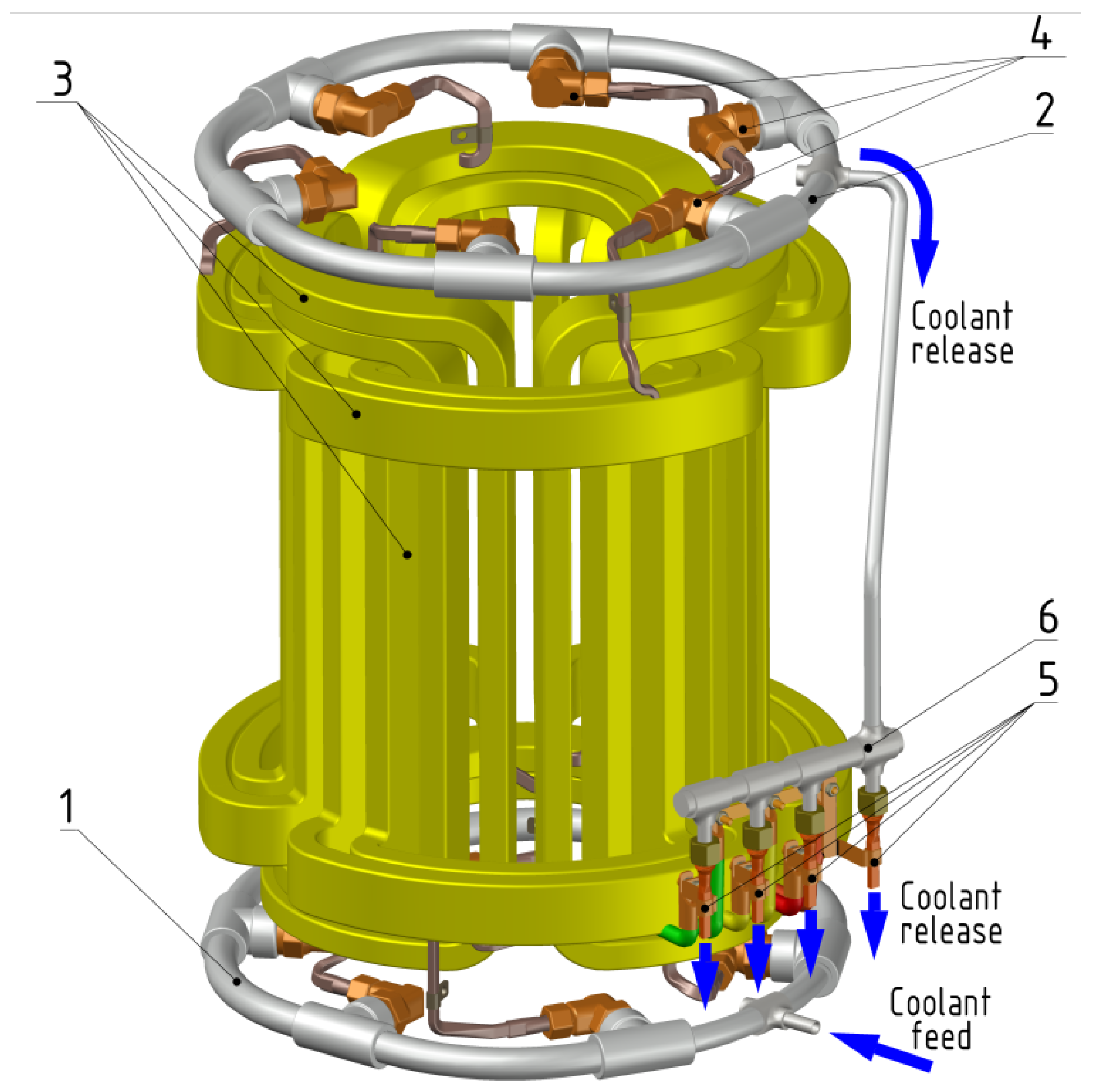
Figure 1. Components of the EMM cooling system: 1. inlet collector; 2. outlet collector; 3. coil channels; 4. fittings; 5. connects; 6. additional collector.
Energies 15 07899 g001
Figure 2. Fitting of the EMM cooling system: 1. tubular coil conductor; 2. a cable tie of the current lead; 3. fitting case; 4. coupling nut; 5. COC pipeline; 6. cable terminal; 7. bolt; and 8. flexible current conductor.
Energies 15 07899 g002
Figure 3. Finite elemental models 1/6 EMM: (a) half-section of the model; (b) the core of the inductor along with the coil and a fragment of the wall of the working chamber; 1: channels in the frame; 2: inductor; 3: frame; 4: coil; 5: compound; 6: the wall of the working chamber; 7: channels in the coil; and 8: adiabatic wall.
Energies 15 07899 g003
Figure 4. Results of calculation of the EMM field temperature (°C): (a) axial section; (b) cross-section; (c) coil; (d) core; and (e) working chamber.
Energies 15 07899 g004
Figure 5. Thermal equivalent circuit of the EMM with independent dual circuit liquid cooling.
Energies 15 07899 g005
Figure 6. Heat conducting flat wall.
Energies 15 07899 g006
Figure 7. Variants of thermal replacement diagrams: (a) without heat emission and (b) with internal heat emission.
Energies 15 07899 g007
Figure 8. Heat conducting cylindrical wall.
Energies 15 07899 g008
Table 1. Input information for thermal analysis.
NameSymbolsValue
1 23
Main EMM electrical indicators
phase voltage, V-100
phase current, A-324
power supply frequency, Hz-50
consumed power, W-9000
power coefficient-0.09
Power loss, W
slot of the inductor windingPs2198
overhang of the inductor windingPw2805
tooth of the inductor corePz15.61
yoke of the inductor corePa58.29
tube of the working chamberPr60
Coefficients of thermal conductivity, W/m K
material of body elements and frameλfrm181.0
material of the working chamber tubeλcm0.16
equivalent to the core of the inductor in the radial and tangential directionsλerτ18.3
equivalent to the inductor core in the axial directionλeaa2.6
equivalent to a heat conducting compound in the internal closed space of the inductor λea0.0485
Heat transfer coefficients, W/m2 K
forced convection in the inductor winding conductor channelsαw11651
free convection of stationary surfacesαw29.0
forced convection from the walls of the working chamberαw315.0
Dimensions, [m] and structural parameters
external diameter of the inductor core Da0.380
inside diameter of the inductor coreD0.208
axial length of the inductor corel10.250
number of clawsZ24
total height of clawshsz0.0446
height of the inductor winding sloths0.040
average width of clawsbsz0.0146
average width of the slotbs0.019
length of the overhang lwo0.050
number of channels in the frame (1/Z)nk1
average channel width in the framebk0.040
channel height in the framehk0.002
average thickness of the frametfrm0.004
length of the frame (channel)lfrm0.394
channel width in conductorbw0.0049
channel height in conductorhw0.0016
number of coil turnswcw14
the thickness of the tube of the working chambertst0.004
Table 2. The overview of the results obtained on the basis of FEM analysis and TEC analysis.
Average Values of Absolute Temperature, °CFEM AnalysisTEC AnalysisDiscrepancy, %
the slot of the inductor coil, Ts58.1755.774.14
the overhang of the inductor coil, Tw56.8257.941.96
claws of the inductor core, Tz82.2378.704.29
the yoke of the inductor core, Ta83.0183.110.117
the wall of the working chamber, Tr112.8119.35.75
Publisher’s Note: MDPI stays neutral with regard to jurisdictional claims in published maps and institutional affiliations.