Review

A Review of Compensation Topologies and Control Techniques of Bidirectional Wireless Power Transfer Systems for Electric Vehicle Applications

1
Electrical Vehicle Charging Research Centre, Department of Electrical and Electronics Engineering, SRM Institute of Science and Technology, Chennai 603203, India
2
Department of Electrical Engineering, Graphic Era (Deemed to be University), Dehradun 248002, India
3
ENET Centre, VSB—Technical University of Ostrava, 708 00 Ostrava, Czech Republic
*
Authors to whom correspondence should be addressed.
Energies 2022, 15(20), 7816; https://doi.org/10.3390/en15207816
Submission received: 13 September 2022 / Revised: 10 October 2022 / Accepted: 19 October 2022 / Published: 21 October 2022

Abstract

:
Owing to the constantly rising energy demand, Internal Combustion Engine (ICE)-equipped vehicles are being replaced by Electric Vehicles (EVs). The other advantage of using EVs is that the batteries can be utilised as an energy storage device to increase the penetration of renewable energy sources. Integrating EVs with the grid is one of the recent advancements in EVs using Vehicle-to-Grid (V2G) technology. A bidirectional technique enables power transfer between the grid and the EV batteries. Moreover, the Bidirectional Wireless Power Transfer (BWPT) method can support consumers in automating the power transfer process without human intervention. However, an effective BWPT requires a proper vehicle and grid coordination with reasonable control and compensation networks. Various compensation techniques have been proposed in the literature, both on the transmitter and receiver sides. Selecting suitable compensation techniques is a critical task affecting the various design parameters. In this study, the basic compensation topologies of the Series–Series (SS), Series–Parallel (SP), Parallel–Parallel (PP), Parallel–Series (SP), and hybrid compensation topology design requirements are investigated. In addition, the typical control techniques for bidirectional converters, such as Proportional–Integral–Derivative (PID), sliding mode, fuzzy logic control, model predictive, and digital control, are discussed. In addition, different switching modulation schemes, including Pulse-Width Modulation (PWM) control, PWM + Phase Shift control, Single-Phase Shift, Dual-Phase Shift, and Triple-Phase Shift methods, are discussed. The characteristics and control strategies of each are presented, concerning the typical applications. Based on the review analysis, the low-power (Level 1/Level 2) charging applications demand a simple SS compensation topology with a PID controller and a Single-Phase Shift switching method. However, for the medium- or high-power applications (Level 3/Level 4), the dual-side LCC compensation with an advanced controller and a Dual-Side Phase-Shift switching pattern is recommended.

1. Introduction

The increase in electric energy demand due to domestic and industrial utilisation is a significant concern for global warming and climate change. The production of electric energy with the adaptation of electric mobility is a growing sector to address the greenhouse effect. EVs commonly identify as a commutable vehicle for consumers. The increased use of EVs has led to an increase in the number of charging stations, which will significantly affect the power system. However, EVs’ other benefits are that they can act as a tiny distributed-energy storage device that supports peak demand, and including bidirectional operation in EV chargers can attract many consumers in the upcoming years [1].
Moreover, with the cost-effective storage feature, EV batteries can function as energy storage devices to efficiently protect renewable energy sources. However, the conventional wired charging method limits the flexibility of bidirectional energy flow owing to the human intervention requirement. Hence, a suitable alternative is required to automate the bidirectional energy flow to meet the instant grid demand. Over a century ago, Nicola Tesla tested Wireless Power Transfer (WPT) technology, which can transmit power over distance through an Electromagnetic Field (EMF). Techniques for transferring power without the necessity of any physical connection have seen an increase in popularity in recent years. Compared with other alternative methods, the inductive WPT technology has several advantages. The primary advantages are: excellent durability without human intervention, automation, limited battery capacity, and galvanic isolation in abnormal environmental conditions. Based on their operating principles, WPTs can be categorised as electromagnetic radiation (microwave or laser) and electromagnetic induction/electrostatic-coupled WPT techniques [2].
The researchers proposed numerous studies on the magnetic coupling of WPT for EV charging applications. These studies majorly discuss two types of applications: stationary and dynamic WPT. Most WPT systems include unidirectional power flow to charge the EV battery. The grid-connected EVs in BWPT systems (V2G systems) make it possible to use EV batteries as a realistic energy storage system to reduce grid fluctuations. It will also improve the variable demand management for networks powered by renewable energy sources. The V2G technology enables the bidirectional energy transfer between the grid and the EV batteries. The DC-DC converters provide the V2G and G2V capabilities of EVs to enhance power flow in both directions [3]. The (AC-DC) and (DC-DC) conversions are two distinct bidirectional power transformation processes used in V2G systems. The Bidirectional AC-to-DC Converter (BADC) works as an inverter and rectifier in the G2V and V2G operating modes. It converts the AC power into DC power and back again into AC.
Additional duties for the BADC include Power Factor Correction (PFC) and harmonic injection into and out of the grid [4]. It regulates the reactive power generated by the leakage inductance of both the primary- and secondary-side compensation capacitors [5]. Increasing the distance between the coils typically reduces efficiency, which is a challenging issue in the WPT system. The leakage inductances between the coil require a compensation circuit. The compensation circuit is primarily implemented on the primary (or transmitter) side to obtain the Zero-Phase Angle (ZPA). It eliminates the need for a reactive power source and allows the appropriate power to be maintained at the transmitter [5]. It also decreases the Volt-Ampere (VA) rating of the power source. The compensation architecture on the secondary (or receiver) side with the same frequency as the transmitter side operates the system in resonance. For increasing the power-transfer rate, the compensation topologies assist in soft-power transistor switching with low switching losses [6]. current are maintained at the wireless charging pad and the load point. WPT’s four basic compensation topologies are represented as SS, SP, PP, and PS [6].
The circuits are usually denoted by “S” or “P”, based on the compensation capacitors connected in Series or Parallel. It is influenced by the coupling coefficient, quality factor, and resonant frequencies of inductances on the primary and secondary sides [7]. Moreover, the semiconducting material-based devices can be soft-switched to achieve a high-power conversion rate. Based on their primary location of compensation topologies, these can be primary or secondary, double-sided, or multi-coil in nature. Numerous transmitting and receiving coil shapes and designs have been proposed in the literature [8]. For various coils, it is possible to relocate the compensating element closer to each coil, separately on the transmitting and receiving sides, or even simultaneously. It makes the compensators control the track voltages within the permissible upper limits.
Moreover, concentrated windings are a perfect choice for parallel compensation because they are frequently used in high-current systems [8]. Apart from the basic topologies, several other topologies have been explored, typically consisting of an inductor and a capacitor combination. These include hybrid-series parallel topologies (LCC and LCL) and S topologies to improve the control of wireless power transfer systems in EVs [7,8]. Each compensatory topology has a particular sensitivity to positional changes or misalignment. Hence, a suitable control method is required to maintain the same resonance frequency on both sides. Various control techniques, particularly for wireless charging applications, have been reported in the literature [8]. The typical PID, sliding mode, fuzzy, model predictive, digital control, and other control strategies are frequently used with all DC-DC power converters [9,10]. Numerous switching schemes are also presented, including Single-Phase Shift, Dual-Phase Shift, and Triple-Phase Shift. These switching schemes primarily focus on improving the performance of isolated bidirectional DC-DC converters [9,10]. In the subsequent sections, detailed discussion on various compensation techniques, control methods, and switching patterns are discussed. In addition, the various challenges, opportunities, and future scope of V2G systems are highlighted.

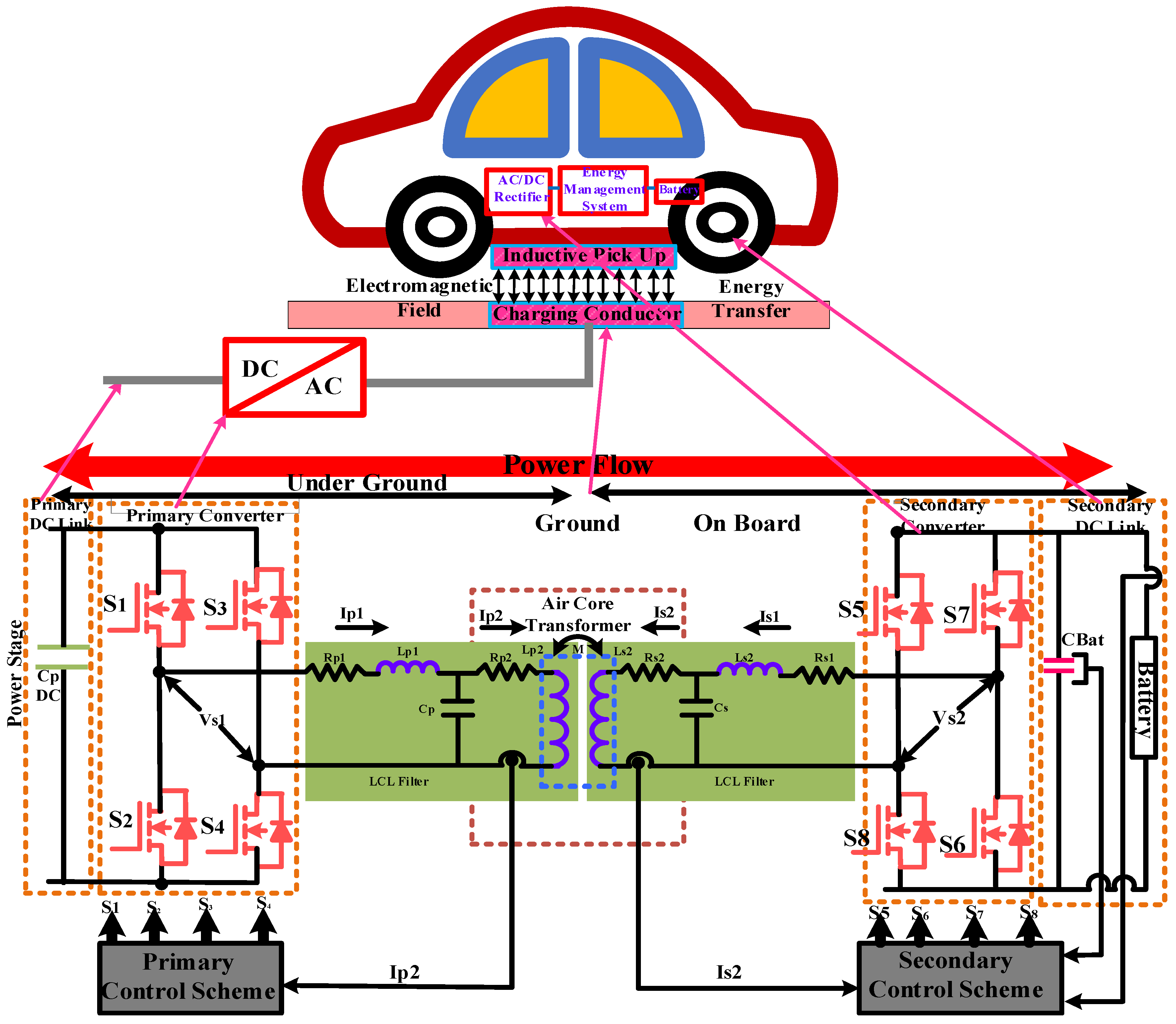
2. General Description of BWPT

The central functional units of the BWPT system consist of a Bidirectional AC-DC Converter, a DC-AC Converter, compensators, and coupling coils. The Full-Bridge Converter topology comprises four semiconductor switches (Q1, Q2, Q3, and Q4) to control the forward power flow. For the reverse flow of current, the diode allows a positive current to flow under these circumstances. The inverter is connected to a DC source as the input, while the load comprises linked coils, compensatory topologies, a converter, and a battery [11]. Additionally, a rectifier converts the AC to DC to feed the inverter. When an alternating current passes through, the primary coil generates a magnetic field based on the shape of the coils. The magnetic field intensity always depends on the current and the frequency. The compensation circuit must be placed between the inverter and the primary coil to operate in resonance conditions. In the literature, different types of compensation, such as SS, SP, PP, PS, and others, are also considered [12]. The functional diagram of the BWPT system is shown in Figure 1.
The same converter topology is used on the transmitter and the receiver sides. These circuits could be used in a bidirectional mode or G2V/V2G. In these circumstances, the circuit components function under different conditions and the battery is in charging and discharging mode. The bidirectional power converter on the secondary side converter acts as a charger and works as the inverter instead of the rectifier. Similarly, the primary-side converter will function as a rectifier instead of an inverter. The functions of a rectifier or an inverter are based on the direction of the power flow in the circuit [6]. In BWPT systems, the resonant circuit is primarily determined by a Full-Bridge Converter that produces harmonic components to minimise the primary and secondary coil conduction losses. Phase-Shift and Phase-Angle Controls are switching controls recommended in the WPT system. The Pulse-Width Modulation has been proposed to achieve system efficiency over long transmission distances.

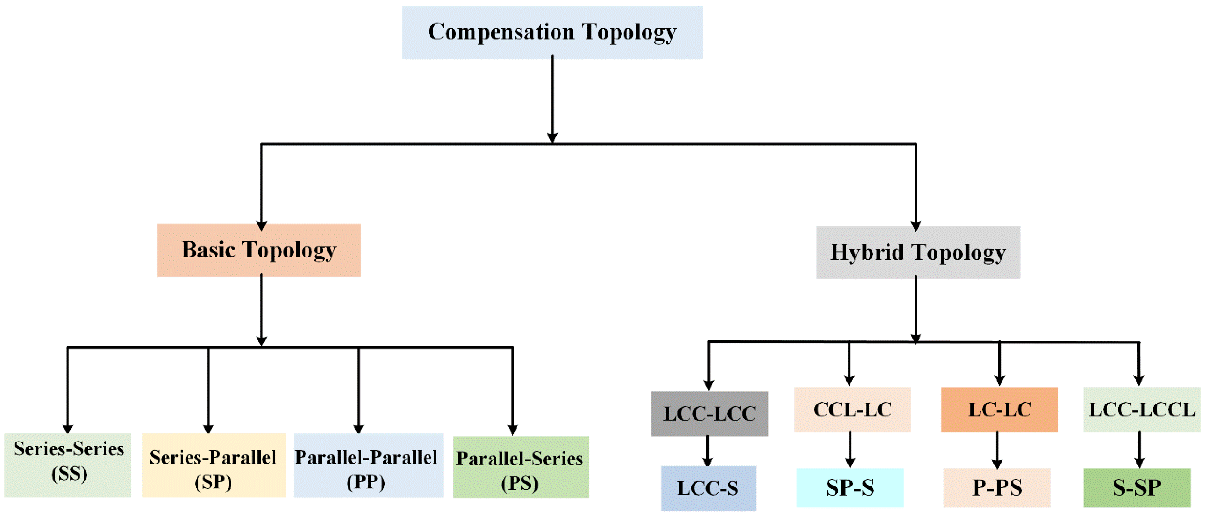
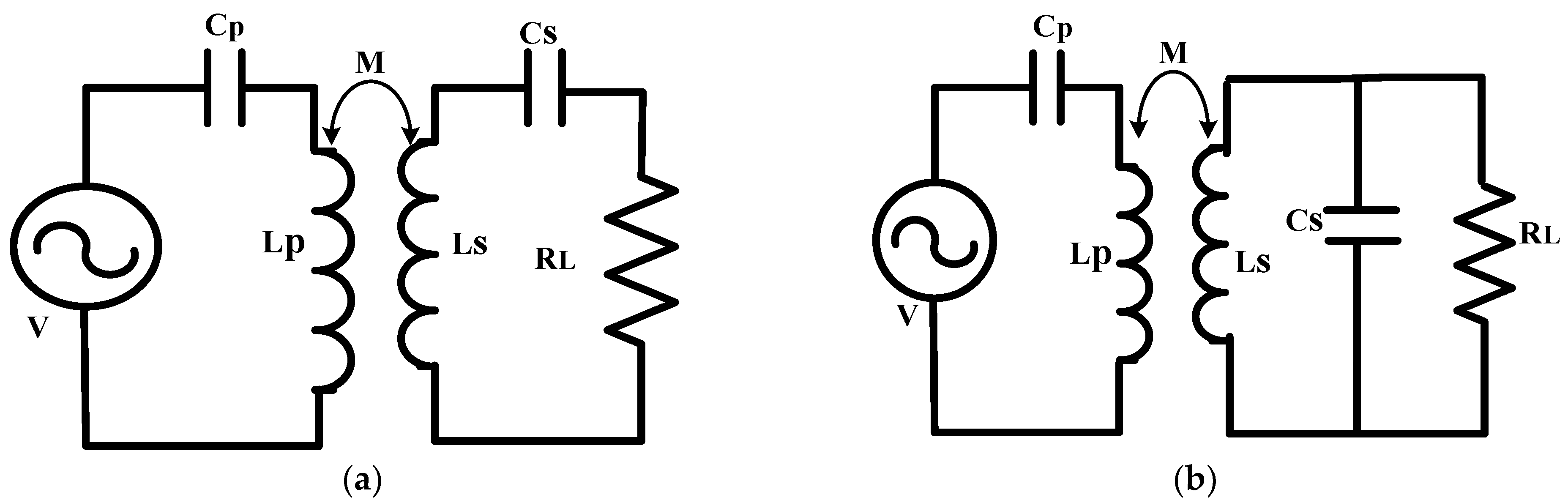
2.1. Classifications of the Compensation Topologies

The compensation topology is considered the most resonant element on a particular side of inductive power transmission. The compensation topologies are classified based on the coil’s positions and the connection circuit as basic and hybrid topologies. The basic topology is further classified into four types (SS, SP, PS, and PP). At the same time, the hybrid topology is classified based on the combination of inductor and capacitor connections [6,7]. It can be a primary or secondary side coil, double-sided, or multi-coil structure [12]. The classifications of all the types of compensation topologies are illustrated in Figure 2.
The compensating element can be positioned on each coil of the transmitter and the receiver side. The logic of resonant compensation is frequently recognised by individual terms separated by a dashed line. The first word specifies the capacitor and the primary coil linked in a Series or a Parallel arrangement. The second term describes the connection between the position of the matching coil and the secondary-side compensation network. The PS and PP topologies are reliable power supply topologies. However, they provide minimal power to the load. The power transmission capabilities and efficiency are determined by air gaps and misalignment. The SS compensation is recommended, because the capacitance value in the Parallel compensation depends on the coupling coefficient (k) factor.
Similarly, if one, two, or more compensating capacitors are connected in the circuit, additional inductance (L) is used. The appropriate combination of inductance (L) and capacitance (C) values for a resonant circuit is administered by primary or secondary side topologies [13]. This also depends on the magnetic coupling coefficient (K) and the quality factor (Q). Furthermore, the compensation topology significantly affects the selection of the primary capacity. The primary- and secondary-side topologies control the ideal ratio of the inductance (L) and capacitance (C) values for a resonant circuit. The primary side compensation topologies and the output characteristics are presented in Table 1.
Based on application requirements, the selection of suitable compensation topology is made. The series compensation is suitable for a primary long-path side-coupled system with capacitors connected along the paths. The voltage and current requirements for Series compensation are higher than the Parallel compensation. SS compensation is more efficient for high-power applications with dynamic load characteristics, such as charging vehicles within multikilowatt loads [14]. Moreover, it is helpful in segmented dynamic WPT applications where the voltage delivered to the secondary is enormously high, with coupling coefficient fluctuations. The equivalent circuits of the SS and SP compensation topologies are shown in Figure 3 [9].
Whenever the receiver is inactive, the equivalent impedance at the fundamental resonant frequency is zero. A significant disadvantage of the SS topology is that only the parasitic impedance of the capacitor and the inductor controls the current. Another disadvantage of the SS compensation is that the load required for the power converter ratio does not depend on the load resonant frequency [11]. Since the SS compensation is independent of the coupling coefficient, interdependence could make control management more difficult. It results in a reduction in load performance [15]. It is also independent of the magnetic coupling coefficient = M / L P * L S , load, or resonance frequency, where M is the mutual inductance, Lp is the primary inductance, and Ls is the secondary inductance. However, the SP architecture depends on the coupling factor and requires a higher primary capacity value for high electromagnetic interactions. The coupling coefficient’s mutual inductance (M) value is used to calculate the primary-side capacity of the SP topology. The secondary compensating capacitor (Cs) is estimated for the SS and SP topologies by substituting the secondary inductance Ls in the equation [16]. The primary input voltage controls the primary-side current magnitude in the SP topology. The SS and SP compensations operate at various resonance frequencies ω max = 1 L s . C s for the selected inductance and capacitance values. They roughly correspond to the optimum efficiency conditions for all the basic compensation topologies. The coupling coefficient influences the maximum efficiency of Parallel compensations. It also influences the various frequencies operating under the conditions of maximum load power [17,18].

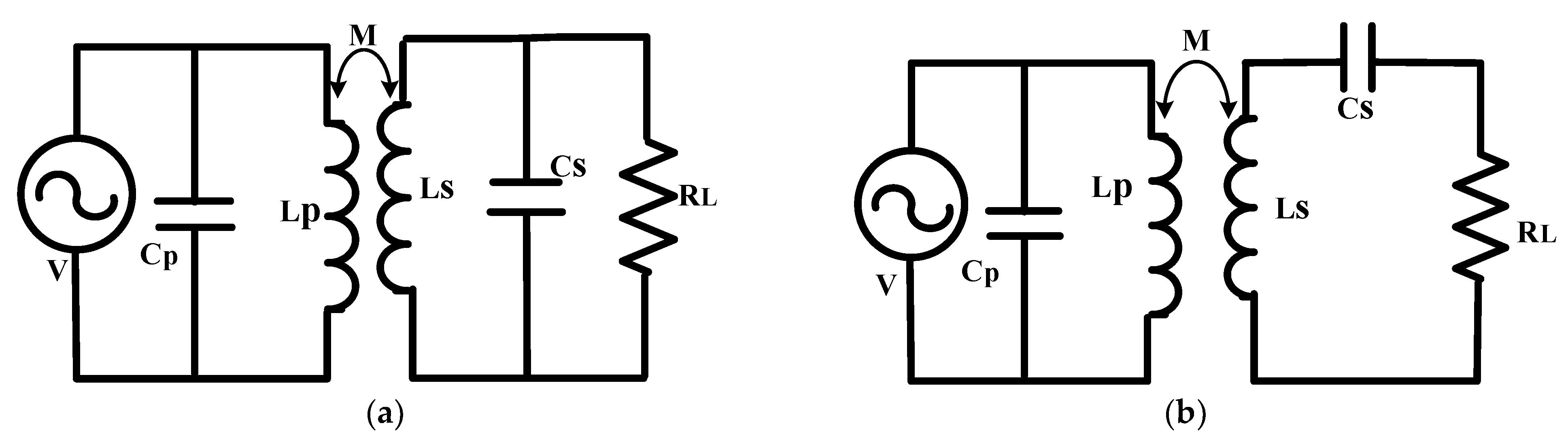
2.2. Parallel–Parallel/Parallel–Series Compensation

The Parallel compensation has indeed increased the investigation, thus making it suitable for both high-current systems and concentrated windings. A single capacitor is connected at the termination of the coil. According to the circuit connection, the Parallel compensation is suitable for higher-voltage and lower-current applications. High-power industrial applications frequently use the PP topology [19]. Even though the primary side of a Parallel compensated circuit uses the current source to make a considerable amount of primary current, the secondary side is mainly connected with batteries. The equivalent circuits of the Parallel–Parallel and the Parallel–Series compensation topologies are shown in Figure 4.
A larger primary capacitance is required for a PP architecture due to poor secondary quality, but this value may be reduced with improved coupling. The PP arrangement has limitations because of poor power factor, high secondary-load voltage, and high source-current requirements. The formulae for the primary capacitance are in two further configurations, PS and PP, with similar primary compensation capacitor [18]. Furthermore, the modification in load resistance affects the value of the resonance capacity in accumulation to the coupling factor change. The topology needs Series’ inductance for superior inverter current management flowing through the Parallel resonant circuit to increase the PS and the PP efficiency [20]. The comparative analysis of the four basic compensation topologies is shown in Table 2.
This inductance raises the system’s cost and the converter’s size. Furthermore, the current source input is necessary to avoid abrupt voltage shifts. Another critical factor is the input resistance, which is much higher in PS and PP topologies. The primary benefits of (PS) and (PP) topologies include excellent efficiency and power factors at a low mutual inductance, also suited for a practically broad assortment of load and mutual inductance changes [18]. In the SS topology, the load and resonance frequency does not influence the output current or self-inductances of the receiver coils; it is better suitable for electric vehicles in stationary and dynamic charging settings. The SP topology requires a substantially lower self-inductance at the receiver coil than the SS configuration [19]. The simultaneous secondary resonance circuit is used to apply a constant current, and this architecture is appropriate for low-power applications. However, the steady-state current input is essential to avoid unexpected voltage shifts. Likewise, the PP architecture is appropriate for high-power applications [20].

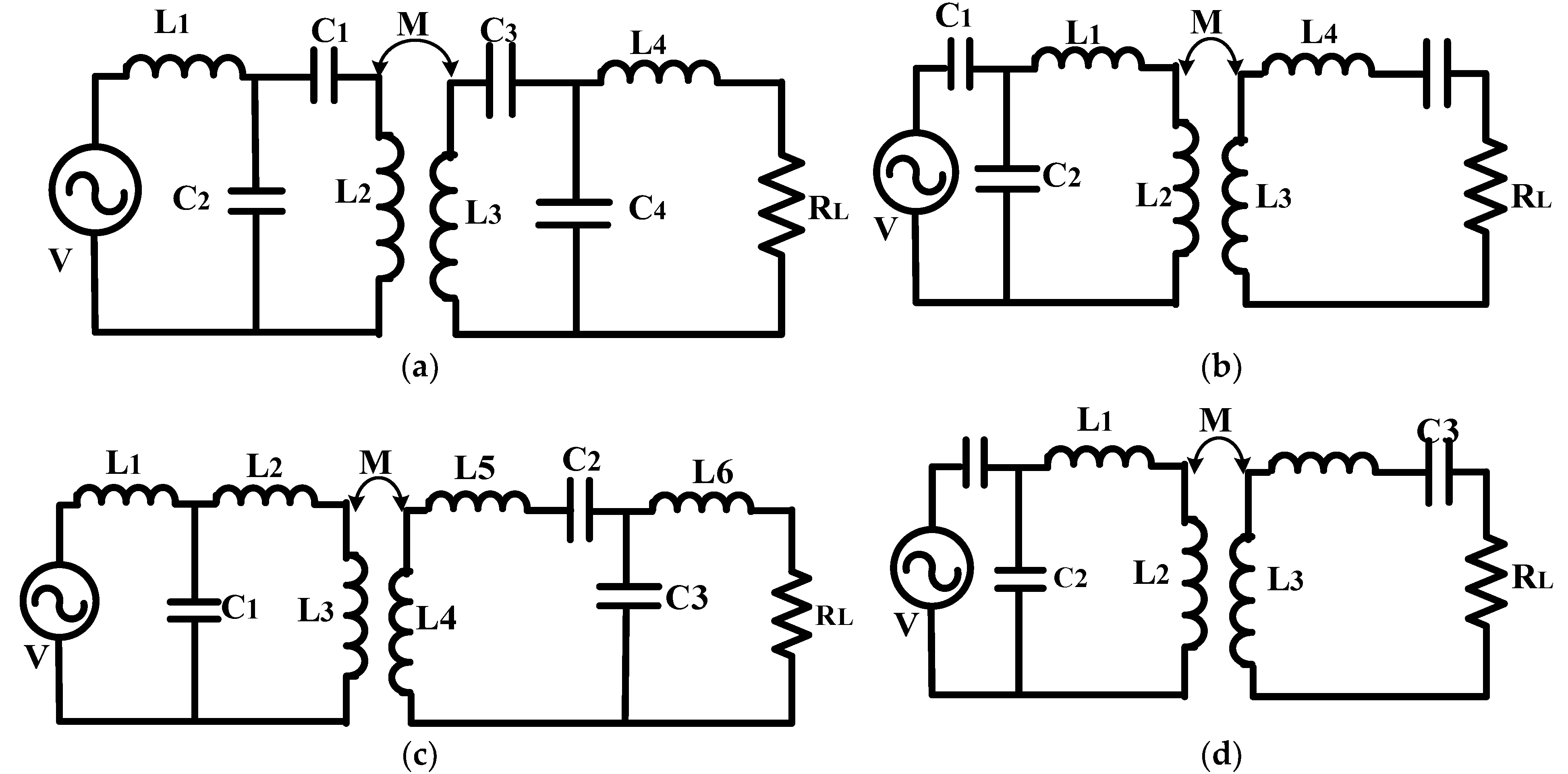
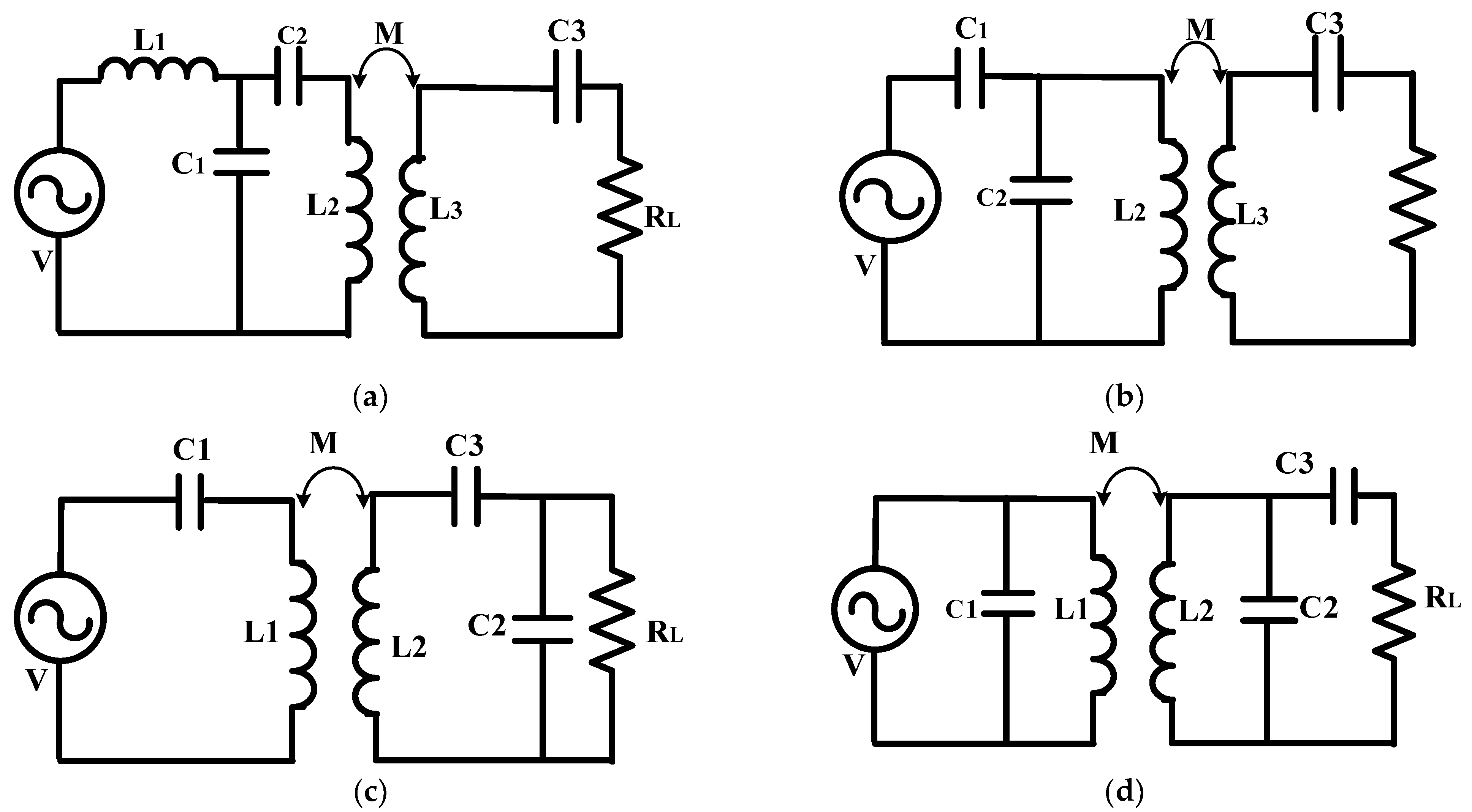
2.3. Hybrid Compensation Topology

The hybrid compensation with a Parallel connection of different combinations of capacitors (C) and inductors (L) is available. These may include supplementary inductances added in Series or Parallel or configurations of two or more capacitors on one side [1,3]. The hybrid topologies (LCL-LCL and LCC-LCC) exhibit a high efficiency compared with the basic topologies [21] The equivalent circuits of the several hybrid compensation topologies are shown in Figure 5. The networks of LCC-LCC [9], CCL-LC [6], LCL-LCCL [7], and LC-LC [19] are illustrated in Figure 5a–d, respectively.
In hybrid topologies with additional inductances and capacitances, the copper loss may be significantly higher than in the SS topology. Hybrid topologies (LCL-LCL and LCC-LCC) retain a high efficiency, particularly in the case of high-power transmission applications [9,22]; this includes supplementary inductances added in Series or Parallel or configurations of two or more capacitors on one side. The LCL-LCL and LCC-LCC topologies exhibit current source characteristics, making them suitable candidates for battery charging applications [6,23]. When the input voltage is set, the overall RMS output current of the double-sided LCC compensation configuration remains constant. Zero-Current Switching (ZCS) can be accomplished by modulating the LCC compensation. Balancing the reactive power on the secondary side, an LCC-power pickup can also attain a unity power factor [9].The load conditions and the coupling coefficients affect this modification. Parallel compensation or Series compensation can be used for the secondary side of LCC compensation. Because of the adaptability of Parallel compensation to changing loads, it is commonly employed [8,24]. The system efficiency is improved by simulating the secondary side of the LCC compensator as both a pure resistance load and a non-linear load. Parallel or Series compensation solutions are feasible for the secondary side. Parallel compensation is commonly utilised owing to its adaptability to load change. An LCL-LCCL resonant circuit is introduced to incorporate the advantages of the two basic resonant circuits. Under ideal circumstances, the double-sided LCC compensation topology is less susceptible to changes in the coupling coefficient [8,9]. The receiver and transmitter of the LCC-S topology use a hybrid compensation topology that combines Series compensation with two additional switches [23]. The equivalent circuits of the several hybrid compensation topologies of LCC-S [23], SP-S [14], S-SP [7], and P-PS [18] are shown in Figure 6a–d, respectively.
The compensation topology can frequently determine the WPT system or the control approach. A novel control technique for a series of LC-LC Dual-Active Bridge (DAB) resonant converter configurations that minimise components is also utilised. The Zero-Phase Angle (ZPA) and load-independent voltage gain are provided by the LC-LC2 topology’s input impedance [24]. The avoidance of higher-order harmonics on the rectifier side and the mutual inductance shift have less impact on the performance variation. The voltage levels of L and C in the inductance–capacitance (LC) series resonance circuit are identical. However, they have reversed phases of this approach compared with the S-SP design. As commonly recognised, there are fewer components in LC-S, but the topological loss is roughly the same as in LCL. That facilitates the integration of the two voltage vectors and reduces the input power source’s tolerance voltage. The (LC-P) adjustment allows the load to achieve more active power [25].
The S-PS topology comprises both sides of the coils (transmitter and receiver), which are connected in Series with the transmitter coil; furthermore, the additional capacitor is coupled in Parallel with the receiver coil. In this topology, the features of SS and SP are mutually combined [15,18]. In the PPS topology, the transmitter coil side of the capacitor is connected in Parallel. Consequently, the receiver side of the capacitor is coupled in Parallel, followed by another capacitor in Series. Numerous researchers have suggested improving the compensation circuit by using an additional inductor and capacitor to fulfil the load requirements [18].
Moreover, the transmitter coil side of L is connected in Series, and C is coupled in Parallel with the receiver coil. Compensation is achieved using a CCL transmitter and an LC receiver (CCL/LC). Parallel resonance is used in the transmitter to reduce the circulating current because a Parallel capacitor offers a low-impedance path. To avoid compensating L, it is advisable to utilise an additional capacitor [18]. The SP/S compensation scheme allows the consistent maintenance of the output power, even under severe misalignment. Increased voltage and current are required for Series compensation compared with Parallel compensation. The coils must be perfectly aligned for the IPT system to transfer power efficiently. The SS and PS topology characteristics are combined in the SP/S topology. This is appropriate for mobile system battery charging, where high misalignment may occur, and it allows for the consistent maintenance of the output power, even under severe misalignment [14]. The constant increase in interconnects with the Zero-Phase Angle of the input impedance might be attained by the suggested S/SP topology [17]. The comparative analysis of the complex hybrid topology is shown in Table 3.
The constant gain value is unaffected by changes in the load or the coupling coefficient. Another advantage of this approach is that the output voltage gains remain insensitive to parameter changes. Under significant parameter fluctuations, S/SP-type compensation may achieve strong output stability and minimal circulation losses [14]. The S/S compensation could not maintain a steady voltage increase at the Zero-Input Phase Angle. In an S/SP compensated converter, the voltage increases at the terminal are less susceptible to transformer characteristics than at the input. Using a compensation circuit (P/PS compensation) with a Series capacitor, including its Parallel resonant circuit, better-tuned misaligned performances are achieved in the PS. So, SP- and S/SP-compensated converters may have great efficiency and gain that stays the same over the range of resonant frequencies [26].

2.4. Theoretical Analysis of Bidirectional LCL Compensation for an IPT System

An LCL topology has suggested that the transmitter coil side of an inductor be connected in Series and the capacitor (C) be coupled with the receiver coil or both sides. The circuit functions as a current source in this arrangement, and the input current is independent of the load current [6]. Consequently, the reactive power is replicated back to the source. The BWPT for hybrid compensation of the (LCL-IPT) system is shown in Figure 7. The circuit is made up of a high-frequency air-core transformer, LCL compensations on both sides, H-bridge converters, and DC links with the control circuit [27]. It achieves bidirectional inductive power transfer from the above circuit, making it easier for the EV to use as a general outlet. The secondary side networks consist of the DC battery of the high-frequency decoupling capacitor ( C B A T ).
Furthermore, the primary side output is connected to the PV array or the DC source output. The source and the load depend on the power flow direction. Along with the converter, full bridge anti-parallel diodes can be controlled to achieve the desired direction of power flow.
For a loosely coupled system, the air-core transformer is used with the following compensation property on both sides: the LCL resonant topology is considered to compensate for transformer leakage inductance. In steady-state operation, assuming the transformer is not saturated, a current will be induced on the transformer [27]. The primary side current (Ip2) will induce a voltage ( j ω M I P 2 ) on the secondary winding. Similarly, the secondary side current (Is2) will induce a voltage ( j ω M I P 1 ) on the primary winding. The selected compensation topology has a significant impact on the IPT system’s performance.
Furthermore, several factors must be considered while selecting a compensation topology. The system’s compensation architecture helps in a variety of processes, such as minimising the VA ratings of power electronics’ converters, achieving ZPA conditions, obtaining soft switching, improving the power transfer capability, and improving the system performance [28].

3. Control Strategies for Isolated and Non-Isolated Bidirectional DC-DC Converters

For practical EV charging applications, there are several configurations and control challenges. As a result, determining the best control strategy for bidirectional converters is critical in WPT design. Isolated converter systems are costlier and more challenging to operate with transformer requirements; especially for low-power applications, isolation is not required [10]. At the same time, high-power applications benefit from isolated topologies with bidirectional DC-DC converters. For instance, phase-shift control technology is frequently used to achieve efficiency, to improve regulation, and to generate soft switching.
Consequently, the non-isolated converters use several phase-shift controllers such as Single-Phase Shift, Dual-Phase Shift, and Extended-Phase Shift [1,3]. Similarly, isolated and non-isolated bidirectional converters are developed to improve efficiency by employing resonant techniques. For DC-DC conversion, hard switching using an interleaving approach is frequently managed to minimise higher power loss. The isolated converter’s output power is modified in buck and boost modes by changing the transformer’s turn ratio. A non-isolated bidirectional converter with a higher conversion ratio has been produced using linked inductors. Soft computing approaches are being studied in these converters to provide a quick dynamic response and other features [29].

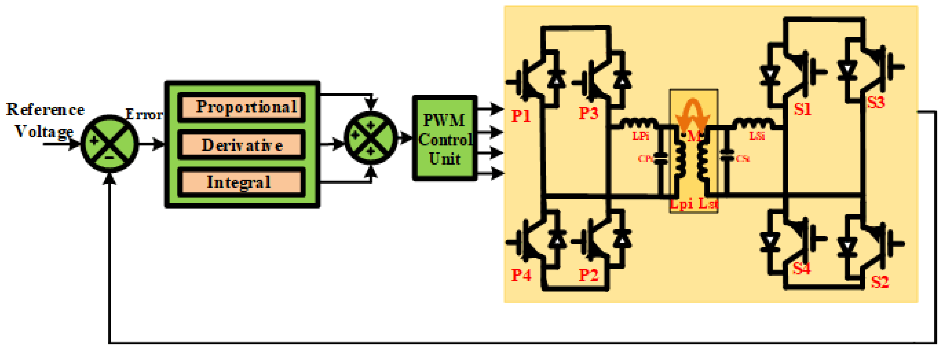
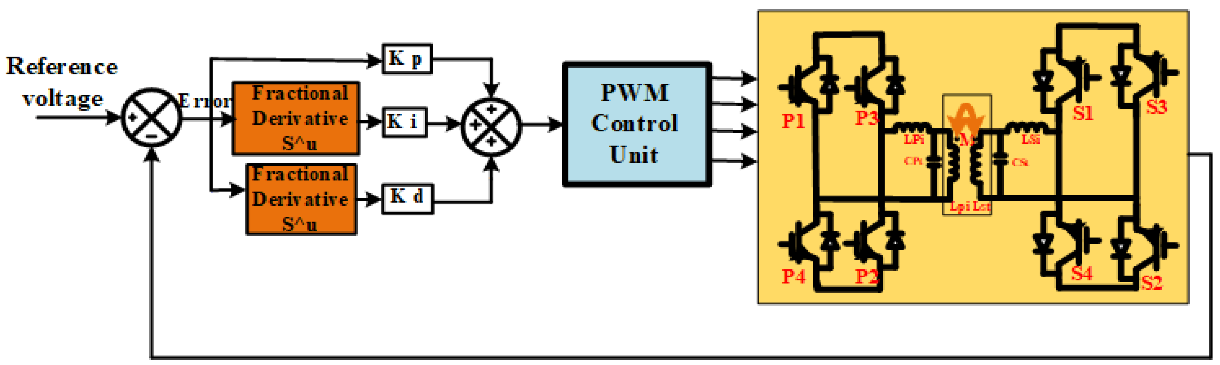
3.1. Proportional–Integral–Derivative (PID) Control

A PID controller regulates continuously powered AC loads by lowering the DC bus capacitor size and switching time. The inverter output is controlled by the PWM, using reference standards. The reactive and active currents are regulated on the alternating current side. When considering the non-linear dependency of the current on the switching frequency, the bidirectional DC-DC converter influences the system’s performance. An isolated voltage controller can be used to improve performance during minimal low-voltage transitions. Because resonant current sensing is complex, additional switch-time control was employed [10]. Figure 8 shows the PID controller-interfaced BDWPT system. If there is dead time, the input voltages between the desired and undesired magnitudes of the current ripple become discontinuous. In this situation, a traditional PI controller might not be sufficient to regulate the entire current range. An alternative technique is needed, depending on whether the converter uses the Steady-State Operation (SSO) mode or the Discontinuous Current Mode (DCM). A PID controller maintains the current in the DCM. However, in the Continuous Conduction Mode (CCM), the PID parameters need to be controlled by an algorithm. Combining numerous converters can obtain an integrated cost-effective system with good power conversion efficiency. For a non-isolated MIMO Multilevel DC-DC converter, a control issue needs the development of an adequate control system. Each converter module is linked to a PID current controller with a substantial inner loop. The current controller regulates the operations and the duty cycle [30].
Properly controlling the inductive current protects the switching components from overcurrent. A PID controller compares the system output with a predetermined value to determine the error signal based on a feedback controller. PID controllers can increase system stability because they have zero control errors and are independent of the measurement. A PID controller was employed to improve the lifespan of the batteries. Although the primary energy source, Fuel Cells (FCs) are inadequate when managing light loads, so a battery must be utilised. In the battery converter, a matching switch is used to reduce the number of sudden changes, to cut down on peaks, and to protect both the active and passive parts from harmful stress [31].

3.2. Sliding-Mode Control

A sliding-mode control is employed in the BWPT system for a non-linear control approach. It is well-known for its quick response, robustness to parameter changes, and ability to handle linear and non-linear systems. The variable structure sliding-mode technology is used to control the rotor angle of the DC motor, using a bidirectional DC-DC converter. When a large signal arises in such a system, an analysis using the state–space averaging model forecasts the regulator’s behaviour [10]. The study shows that in a steady state, the system is not sensitive to changes in output voltage. The discontinuous surface is made up of the output voltage, output current, and induced magnetic coupling between the inductors. Three sliding surfaces are tested for each of the bidirectional Cuk converter’s three switching states.
Figure 9 represents the functional block diagram of the sliding-mode controller-interfaced BWPT system. A non-linear model is adopted in the sliding-mode controller to control the range of switching converters with a high-pass filter. The DC bus voltage can be controlled to reduce the transient response during non-linear load fluctuations. A voltage-mode op-amp is used in the first arrangement, whereas a current-mode transistor is used in the second arrangement [32]. Sliding-mode control is also used in a DC-DC converter that works in both directions and in energy storage systems with supercapacitors.
The DC bus voltage should be controlled using a reliable sliding-mode controller in this case. High structural insensitivity is shown by the recommended sliding-mode control method, which may integrate numerous strategies to utilise the benefits of various control systems. Researchers may integrate numerous strategies into a single system. For instance, dual PI controllers are used in the traditional cascade control technique, one of which regulates the inductor current and the other regulates the high-side capacitor voltage [33]. When the PID cannot deliver the required performance under particular circumstances, the PI regulator is coupled with a non-linear stationary sliding-mode technique to produce stable behavior and functionality [34]. A fuzzy sliding-mode controller is created to resolve the chattering problems in the sliding-mode control by renewing the energy of an ultracapacitor battery. When these two controls are used together, there is a lot of flexibility, even when things go wrong, and there is less difference between the actual and the intended response. The Adaptive Sliding-Mode Control (ASMC) is used in hybrid vehicles and EVs to achieve current-tracking control for power converters [35]. The performance of the ASMC was improved using an Optimising Reaching Law (ORL), and stable power distribution is obtained. The ORL-based ASMC output performs the conventional ASMC techniques regarding tracking control and power distribution. According to previous research, the sliding-mode control may be used to operate a buck–boost bidirectional converter]. The recommended system has better stability when the input voltage and the conversion load fluctuate and do not require a second sensor. The SMC is used to fix the DC/DC converter problem with harmonics in EVs [36].

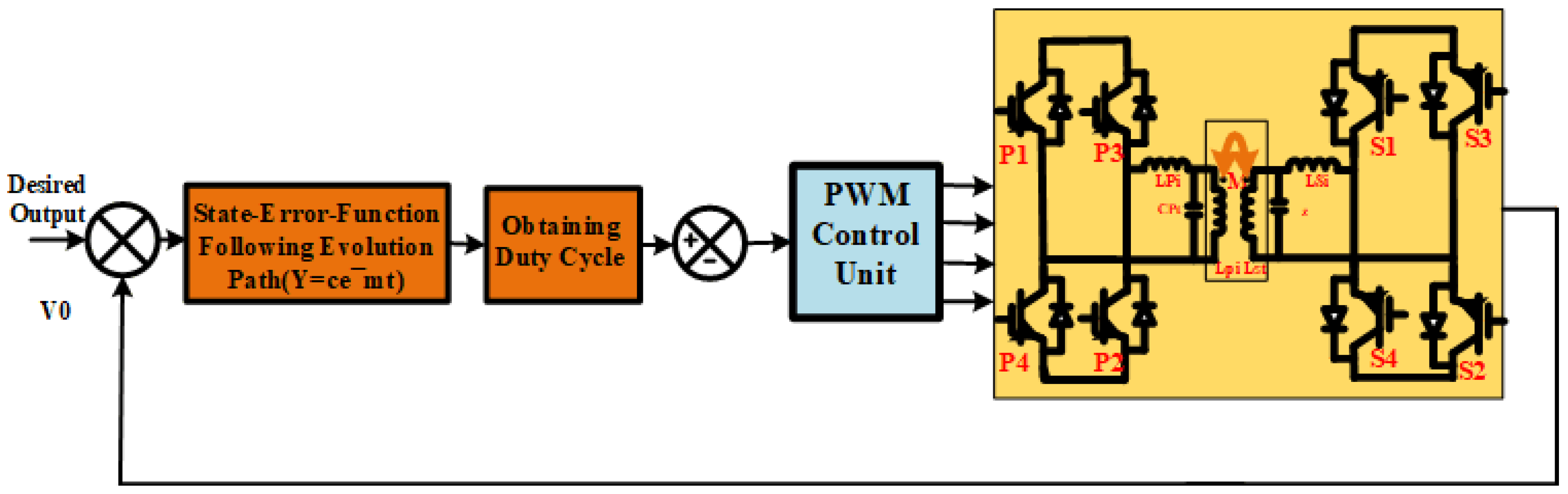
3.3. Dynamic Evolution Control

Figure 10 represents the functional block diagram of the Dynamic Evolution Control (DEC)-interfaced BWPT system. An EV system should be able to change rapidly to accelerate and decelerate. Hence, additional energy storage is required to meet the increase in load demand. The converter and the ultracapacitor improve the dynamic fuel cell system, enabling the Fuel Cell-powered vehicle to accelerate rapidly and to adjust to changes in load conditions. The combination of ultracapacitor energy storage in EV systems uses a bidirectional DC-DC converter. Dynamic evolution control is used to design and implement the converter control scheme [10].
The DMC is creative and is used to create an interface converter for control. Even when the load current varies rapidly, the controller controls the total current flowing through the energy storage system to minimise the potential difference at the DC bus. The controller can adapt to shifting loads and can immediately restore the normal voltage whenever the Fuel-Cell output exceeds the required load. Inductor current changes and input/output voltage swings may all be considered using DEC. It aids in improving the system’s dynamic performance [37].

3.4. Model-Predictive Control

Model-Predictive Control (MPC) is a subset of predictive control implemented to ensure that the system variables fulfil their reference values. Conventional bidirectional DC-DC converters in battery applications use them because of their fast dynamic response and ease of implementation with microprocessors. The prediction and optimisation modules should appear in a typical MPC, followed by a precise time model system. Figure 11 shows the functional block diagram of the BWPT system with an MPC [10].
The suggested MPC schemes, sequential MPC and Wide Dynamic Sequence Control (WDSC), are separated into three modes: charge, discharge, and idle. The MPC controls are used in the bidirectional DC-DC converter based on this pre-set rated range and DC bus voltage control [38]. A multi-system is incorporated into the proposed multi-MPC to integrate the non-linear processes of each model under certain operating circumstances. The proposed approach successfully resolved this issue, which deals with significant non-linear behaviour for many MPCs. The overall dynamic sequence control system uses a non-linear model to give an accurate real-time linear model for each sampling period [39]. This is done to reduce the difference between linear and non-linear models.

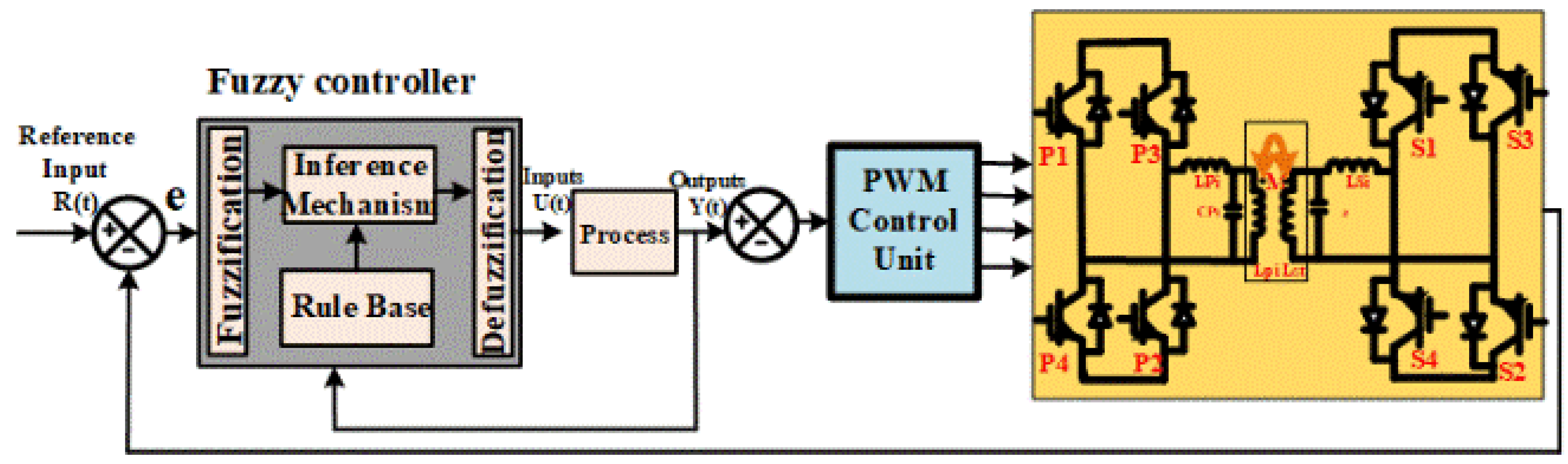
3.5. Fuzzy-Logic Control

Implementing fuzzy control allows a sophisticated and precise system with unknown parameter fluctuations and load interruptions to provide consistent responses. The non-linear and instantaneous characteristics of power converters make it challenging to understand the characteristics of a single converter. The primary objective is to implement bidirectional DC-DC converters to build a Fuzzy-Logic Controller [10]. Numerous technical studies have evaluated FLC and determined that it performs better than regular controllers. The type of Membership Function (MF) typically affects the Fuzzy-Logic Controller’s efficiency based on rules and quantity of regulations. FLC’s four stages are fuzzification, rule base, inference engine, and defuzzification [40]. Figure 12 represents the functional block diagram of the FLC controller-interfaced BWPT system.
In photovoltaic lighting systems, the implemented Fuzzy-Logic Controller provides rapid dynamic characteristics. Whenever the impact of increasing the grid voltage on supercapacitor performance is considered, the controller is a reliable way to manage the dc-link voltage. In some situations, it is challenging to implement a non-linear control rule for the system and Fuzzy-Logic Controllers are an excellent option [41]. The charge and discharge of the Dual-Active Bridge (DAB) converter battery can be carefully controlled with the help of a Fuzzy-Logic Controller over time. An Artificial Neural Network (ANN) is a more advanced way to control a system. It can be used with any system because it has changed over time [42].
However, an FLC does not always guarantee that it is the best alternative. Multiple-input power electronic converters are being developed for EV applications for low-priced, adaptable, and effective functioning, including Minimal Electromagnetic Interference (EMI). In these applications, the power transfer between the sources and the loads is coordinated using a fuzzy system [43]. A bidirectional DC-DC converter configuration based on FLC has established low cost, fewer components, and high EV efficiency. An FLC-based bidirectional converter has been proposed for EVs to manage the charging and to discharge currents of batteries, resulting in a larger battery with a longer lifespan [44].

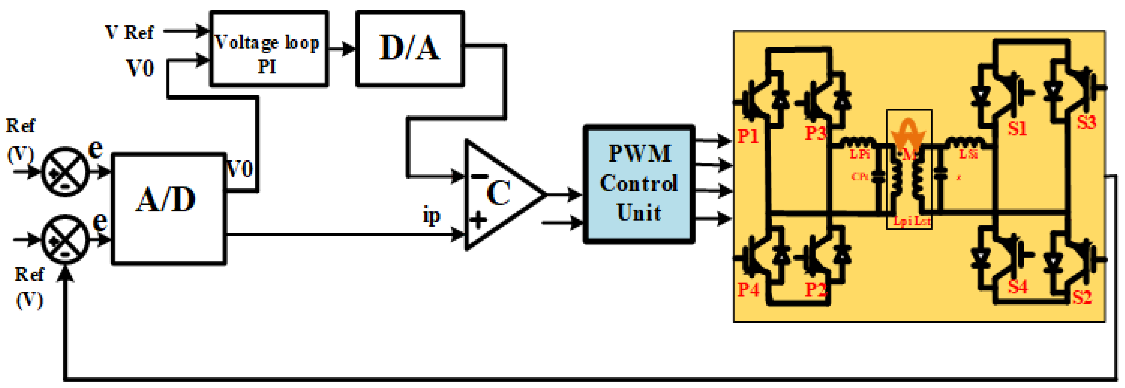
3.6. Digital Control

Due to an increasing number of embedded electronics, Digital Control (DC) has been implemented in bidirectional flyback converters. The DC system utilised the analog-to-digital (A/D) interface to handle the error signal as input before analysing the data. The system output is initiated when the controller receives a discontinuous signal and the system’s output is ideal in other conditions [10]. A DC is used during processing to implement valley-switching technology. In this technique, a high-speed comparator compares the drain MOSFET’s source and input supply voltages of a low-voltage MOSFET. The microcontroller produces a fixed on-time pulse after receiving the comparator output signal. The control method is highly effective and rapidly charges and discharges the battery [45].
Figure 13 represents the functional block diagram of the DC-interfaced BDWPT system. Digital systems provide much more versatility, better EMI immunity, and the ability to monitor processes and malfunctions using an external system or a wireless device. This conversion increases the conversion efficiency of low-voltage distribution networks, which will be implemented on just the contemporary Digital Signal Processor (D.S.P.) [46]. The approach employs a Hybrid Digital Adaptive (HDA) control approach to improve the transient responses in bidirectional DC/DC power converters. Researchers have examined the construction, the circuit parts, and the control of quick converters for pulse development, servomotor applications, loading corrections, and sound enhancements [47,48].

3.7. Boundary Control

Using time-varying circuits, the switched converters can be symmetrically controlled using Boundary Control (BC). In buck converters, the second-order switching surfaces can be utilised to increase the circumferential speed of both trajectories along the sliding surface to deliver optimum overall responses [10]. The two most popular Boundary Control strategies are Adaptive Hysteresis Control (AHC) and SMC. Bidirectional DC-DC converters are operated using switch modulation schemes obtained by determining state variables. A curved switching surface was generated from the standardised domain, enabling any combination of boost converter settings. This BC approach converts outstanding and dynamic behaviour, with no overshoot and time-optimal responses to loads and start-up disturbances [49].
There are several methods for improving DC/DC converters. To improve the dynamics, AHC has been used in numerous studies. A new boundary is formed using the zero-inductor current when the converter is operated in discontinuous-conduction mode. The operational point is along the on-state route, whereas the off-state path is the best switching surface for BC when the state is above the load line [50]. It has been proposed to use an initial switching interface for the Boundary Control of a power converter. Implementing BC is challenging, despite its existence, because of the time and energy required to generate the minimum response times. In buck converters, the large-signal responses can be closed, the angular velocities of the pathways can be increased, and the sliding surface can be increased using a method based on a second-order sliding surface. Due to the efforts required to create minimal-level responses, Boundary Control is challenging, even if it is essential [51]. The overall comparison of the control techniques of bidirectional (DC-DC) converters is shown in Table 4.

4. Techniques for Switching Modulation Strategies of Bidirectional Dc-Dc Converters
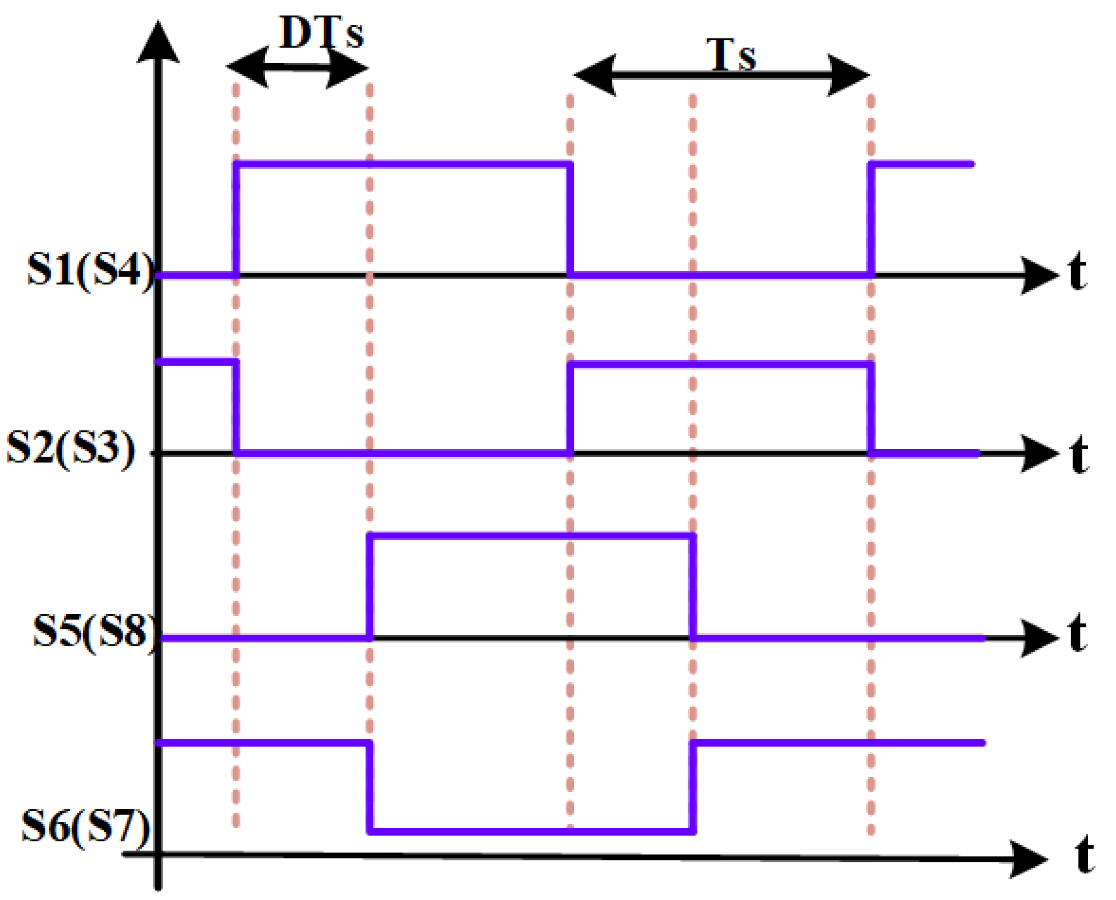
A control approach is essential to achieve high efficiency, minimum transfer loss, and reduced Total Harmonic Distortion (THD) in EV-converter topologies. The control approach is vital to two popular control methods for switch-mode converters: Pulse-Width Modulation (PWM) and Phase-Shift Modulation (PSM). The power DC/DC converter regions require different control strategies and adjustment techniques [52]. The most popular control method for standalone bidirectional converters is Phase-Shift Control, developing soft switching, Phase-Shift controllers, better regulation, and increased efficiency. Numerous control techniques have also been used to generate dynamic responses from non-isolated converters. A bidirectional DC-DC converter is a key element that contacts renewable energy sources in energy storage systems [53].
The converter’s voltage level can be changed by using appropriate switching techniques. According to its bidirectional capabilities, the performance improves when the system size decreases. This eliminates the requirement for forward and reverse power converters. A DC-DC converter regulating technique must have a quick distinctive response and hold the output DC voltage constant throughout the power streams (forward and reverse). A summary of several bidirectional DC converter control systems, including basic analysis of these technologies, follows. To improve the system performance, it also looks at the best ways to control the power flow in both directions using switching technique [54].

4.1. PWM Control

The bidirectional DC-DC converters have several significant problems, including the control of the output voltage. A PI controller is frequently used to differentiate between the operating modes and it can regulate the voltage in the converter step-down mode [55]. Instead of a PI controller, a duty-cycle ramp from zero to a fixed value is often used to turn off the output voltage whenever it decreases below the reference level. Maintenance of the reference and rejection of the interruption is ensured in the system’s only functional stable state [56]. The different PI controller controls the current in the step-up (boost) mode. Although PWM is simple to operate and set up, it has a low performance [57], as previously stated.

4.2. Single-Phase Shift Control

The converter is developed using high-performance switching devices that can accurately manage the phase shifts. The converters are capable of Zero-Voltage Switching (ZVS), Phase-Shift adjustment, and limiting the increase in power in both the forward and reverse modes. Fundamental bidirectional DC-DC converters produce square-wave voltage waveforms across their inductors. A novel set of interconnected multi-input switching phases is used to shift bidirectional DC-DC converters. There has been a limited ZVS range, high-voltage flow, power loss, and duty cycle, as well as a high-voltage rating and reverse recovery on the extra-side rectifiers [10].
A DC-DC transformer is an independent open-loop regulated converter that functions at a fixed duty cycle of 50%. Therefore, all switching devices may always be soft-switched using permeability or magnetising inductance. However, the output voltage or power of a DC-DC transformer cannot be adjusted. When soft switching is implemented, the Single-Phase Shift (SPS) controller can perform only a minimal number of arrangements. Researchers have been interested in these restrictions to develop new ideas to overcome these difficulties [58]. Figure 14 shows the Single-Phase Shift control method waveform for BWPT.

4.3. PWM and Phase-Shift Control

The combination of PWM and Phase-Shift Control (PPS) is used to reduce the conduction losses in the circuit. Determining an appropriate turn ratio for a transformer is a complex task. Maintaining a constant leakage inductance at the current sleep rate is impossible. A PPS-based controller is developed to maintain the pulse repetition rate throughout the power transfer stage. When the load changes because of intrinsically variable circuit elements, the output power or the system’s parasitic characteristics can change [10]. This is true even if the turn-ratio mismatches do not change. The PPS control method can be used in the case of multiple bidirectional converter circuits. The PWM control can be used to ensure the voltages on both sides of the converter are often the same. The converter’s duty cycle is changed with a PI controller’s help, making it better at soft switching [55]. Figure 15 represents the equivalent circuit of the PWM and the Phase-Shift Control approaches.
SPS control is preferred to eliminate reactive power and to increase efficiency [55]. The switching losses increase with a higher switching frequency, and this converter integrates PWM control with Phase-Shift Control. This technique offers ZVS for all switches without the use of auxiliary switches. A DC-DC converter in both directions is controlled through a Phase Shift and a PWM. The PWM duty cycle regulation is an ideal transformer between a constant input and output voltage [28]. The PPS control is better than Phase-Shift Control because it can lower the converter’s RMS current and current stresses. Current-fed switches are affected by high-voltage spikes and loss of circulation conduction. A novel Phase Shift with Pulse-Width Modulation (PSPWM) controlling ZVS bidirectional DC-DC converter is presented [57]. PWM control is used to control the positive amplitude of the equivalent input voltage, which is identical to the equivalent output voltage. On the other hand, the current stress present in the switches is asymmetrical. High-power bidirectional conversion is not appropriate for DC-DC converters [29].
The PWM + Phase-Shift (PPS) Control provided for an asymmetric DC-DC converter is, therefore, unsuitable for significant input and output voltage fluctuations. Circulating conduction loss is reduced, but it biases the magnetising current and places an excessive load on the primary switches. Pulse-Width Modulation (PWM) with a Phase-Shift (PPS) Control technique is appropriate for a subset of IBDCs. In PPS converters with two output levels, duty cycle adjustment provides low-current stress, a wide input voltage-fluctuation range, and all acceptable ranges [56].

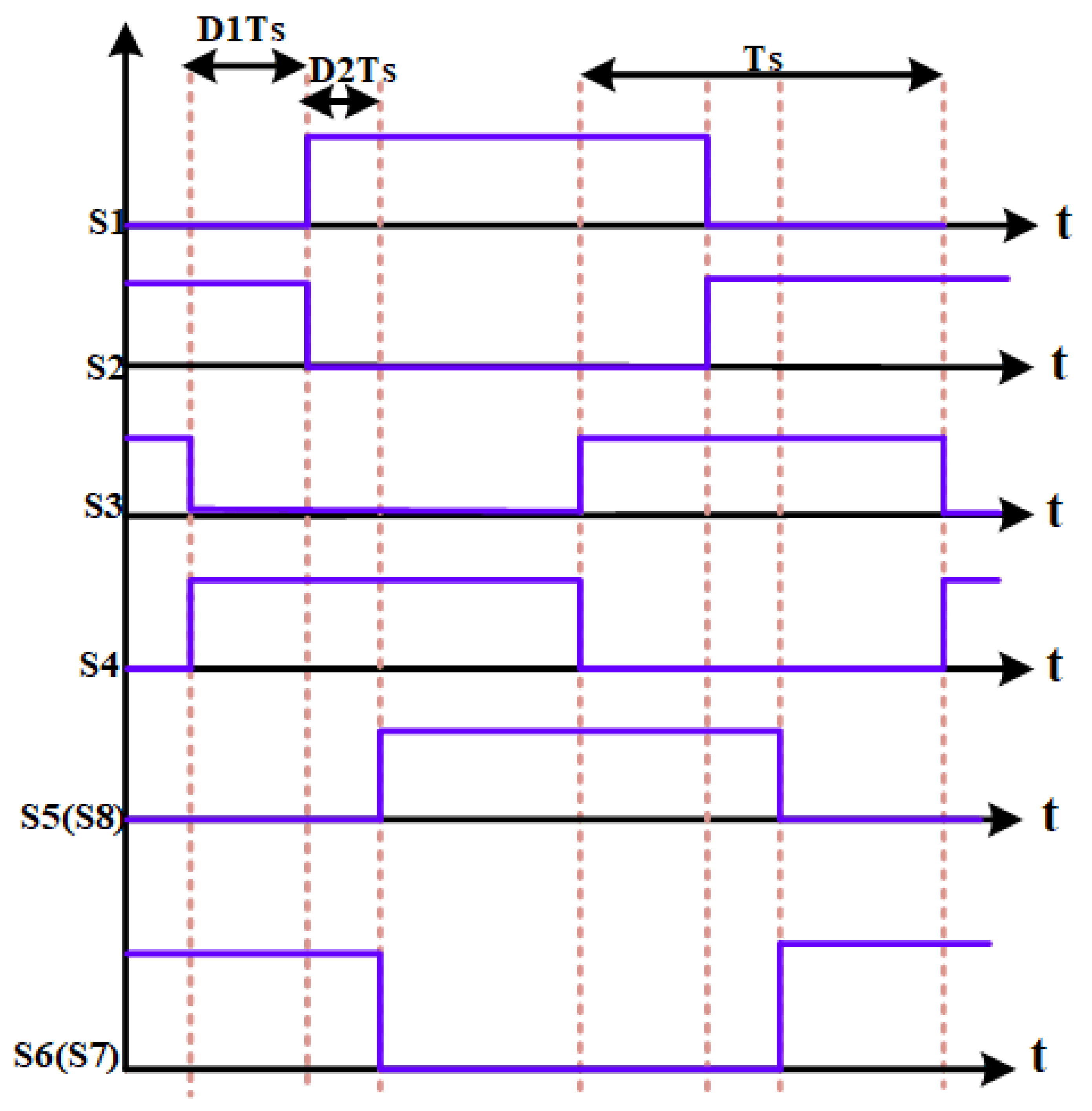
4.4. Dual-Phase Shift Modulation

The transformer leakage inductor controls power flow in the SPS. Expanding the Phase Shift can reduce the backflow power. In response, both the circulating power and the current stress are increased. This can cause serious problems in both the electric and the magnetic systems. The isolation transformer’s primary- and secondary-voltage phase differences were employed; however, an additional Phase-Shift ratio (D1) was suggested for this control strategy. A Dual-Phase Shift (DPS) is a type of extended Phase Shift that lets the transmission power be controlled over a wider range than with a typical (SPS) [10].
The DPS control minimises the inrush current during the converter’s start-up process. This method is helpful when creating a secure functioning zone for high voltage or for power converters that are rugged. Compared with the SPS control, the dead-band impact is simpler to mitigate with DPS control and it can increase the range of power transmission [59].The Isolated Bidirectional Dual-Active Bridge (IBDAB) DC–DC converter performance can be significantly improved by DPS control. DPS control may improve the system’s efficiency, eliminate reactive power, limit inrush, and lower peak current and output capacitance. Compared with TPS control, EPS control enhances the regulating flexibility, improves the regulating range, and boosts the transmission power while reducing the current stress and improving the system efficiency. The cross-connected switch pairs in both H-bridges were switched individually during TPS control to produce phase-shifted transition square waves on the primary and secondary sides of the transformer [60]. Figure 16 represents the switching pattern for Dual-Phase Shift control.

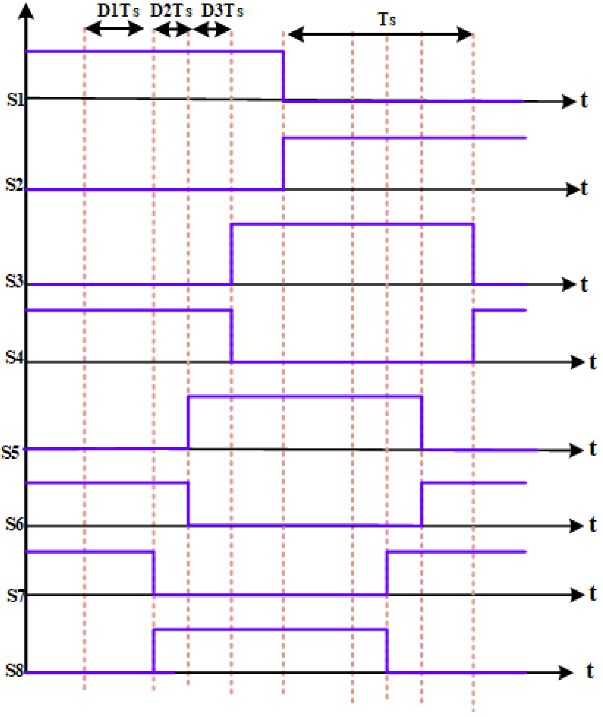
4.5. Triple-Phase Shift

This design may benefit from improving the operating range of soft switching, battery storage systems, fast charging applications, power converters in electric train engines, and other systems. It has been proven stable even when the operating parameters are arbitrarily modified. However, certain restrictions exist on choosing an appropriate control parameter to increase the present stress [10]. The duty cycles of Single-Phase, Dual-Phase, and Three-Phase switches are one, two, and three, respectively. The power switch in Phase-Shift systems is triggered by these duty cycles. In SPS, DPS, and TPS, appropriate control signals must be produced using the duty cycle. The Lyapunov function method is used to check the stability of the converter at each level.
A novel Phase Shift TPS control strategy was used in this power circuit, which enables the system to operate with high efficiency over a broad load range. The Lyapunov function is used to assess the stability of a non-linear bidirectional DC-DC converter when its parameters change significantly [61]. A TPS controlled a DAB to make it more efficient by increasing the ZVS range and by reducing the losses caused by substantial soft quantity. The TPS may do this by using Triple-Phase Shift modulation as an extra control variable while running a DC/DC converter. Figure 17 represents the switching pattern for the Triple-Phase Shift control approach.
A novel TPS control approach is developed for an isolated bidirectional Dual-Active Bridge (DAB) DC-DC converter to increase the smooth-switching operating range and to improve efficiency [62]. The overall performance and comparison of the bidirectional (DC-DC) converter’s switching strategies is shown in Table 5.

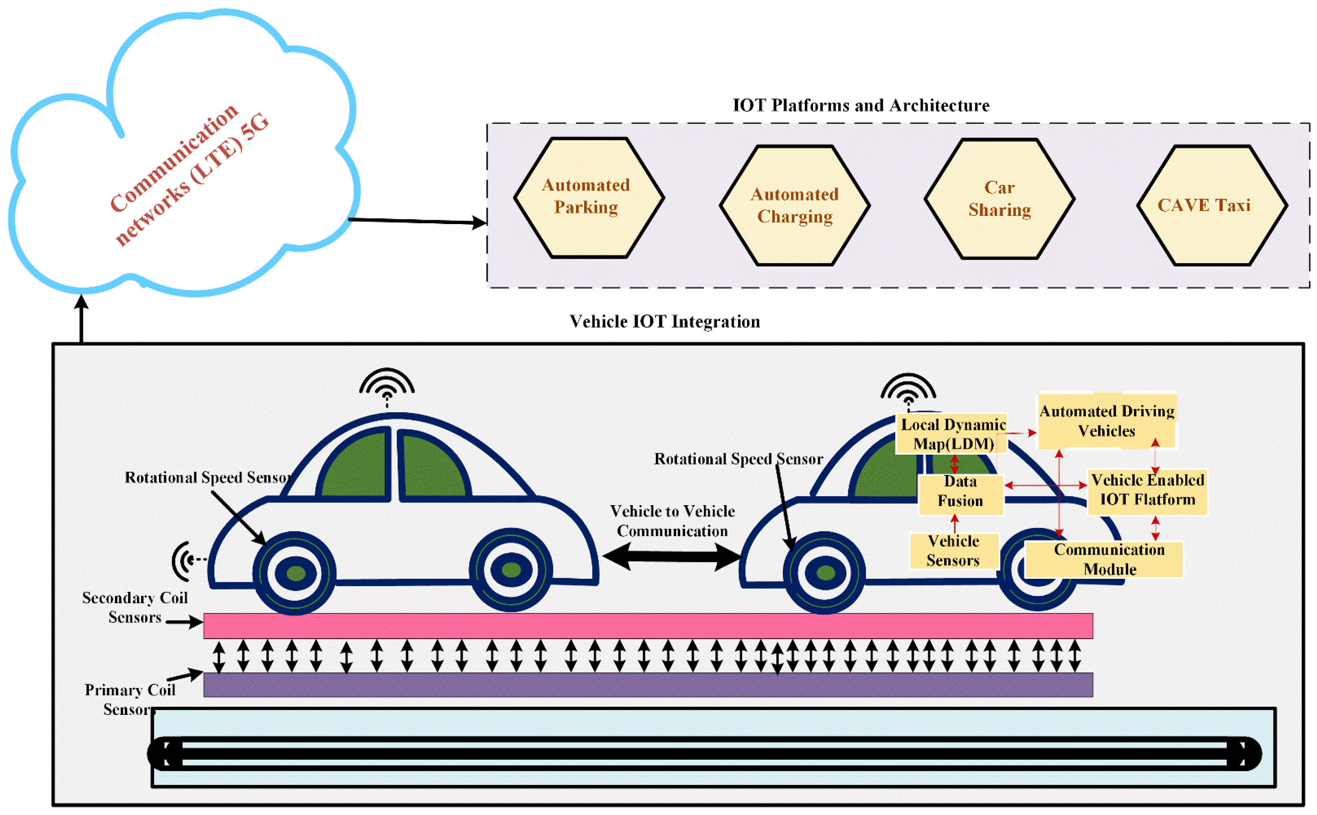
5. Internet of Things Interface in Bidirectional Wireless Power Transfer

The WPT methods are employed to forecast the state and to build controllers for Internet of Things (IoT) communication networks. The IoT is a collection of physical things that are extensively connected via the Internet. Monitoring data are gathered via WPT systems with IoT components, such as sensors. As the IoT may offer more connections, better sensors, data processing, and flexibility, it is a practical technology for observing WPT behaviour. Consequently, IoT-embedded intelligent technologies can enable two-way communication between WPT system centres and control centres to collect information on the usage of WPT systems, the IoT components and sensors, as well as the present state of these systems [63].
IoT is a network of smart things (also known as Internet-enabled items) and the web services that interact with them. It has the potential to link smart computers without human involvement. Figure 18 shows a functional diagram of IoT in the WPT system. The Internet of Things (IoT) is increasingly being used as a transmission channel, with integrated smart devices sending information to a central processing hub for real-time display. They can be used in various applications, including smart grids, interfacing the EVs, with (IoT) WPT systems, communications, healthcare, and environmental monitoring [64]. Figure 19 represents the IoT with an EV interface.

5.1. V2G on Bidirectional Wireless Power Transfer

Bidirectional wireless charging is also described as Vehicle-To-Grid (V2G) integration, a unique technology that allows EVs to discharge to the grid when required. Utilities can benefit from two-way communication between vehicles and the power grid to effectively manage electricity resources. The EVs operate as energy storage units, providing demand-side management services for the grid through frequency control, spinning reserves, and peak shaving [65]. It is an alternative to communication between vehicles and the grid system and vice versa. The EVs are connected to the grid through the V2G system, a renewable energy management system that supplies energy storage in the EV batteries. The overall calculation of the power transmitted back to the system is performed as per EV standards. Consequently, the energy stored in the EV battery does not return to the grid, irrespective of whether there is a demand for power or an available supply. Electric Vehicle Supply Equipment (EVSE) provides various power levels, ranging from EV to grid [66].
All Level 1 and Level 2 chargers are compatible with the (AC) power source provided in the internal power converter, which generally converts AC to DC voltages. The V2G mode contains an inverter, which converts the DC voltage source to an AC voltage source, which is used for charging the EV batteries. There are two requirements for the design of power electronic devices: to interface with a real-time system administrator and to establish a V2G system, for which the EV needs the three most essential elements: a specific charger, bidirectional power transfer, and communication capability. The power capacity of the charger and the communication capabilities are the most important factors, whether they are located onboard or offboard the vehicle [67].

5.2. Strengths of V2G Technologies

The active power or renewable energy sources provided by V2G and V2H technologies ensure that the reactive power in the current grid is balanced. It will provide income for the EV owner by providing renewable energy power with lower emissions and operational costs compared with ICE engines. EVs offer a potential backup for renewable energy sources, such as wind and solar power. The presence of EVs enables G2V and V2G revenue growth in the smart distribution system [68]. It is more affordable to use V2G or V2H technologies to provide backup during periods of high demand than to expand the capacity of current energy sources or to develop new energy sources, both of which require large expenses. EVs provide more reliable, secure, and continuous energy backup or emergency power assistance than solar, wind, or other renewable energy vehicles. The EVs’ owners may charge at night at a low earning rate by providing electricity to the grid during the daytime peak expensive period [69].

5.3. Weakness of V2G Technologies

Due to the charging and discharging cycle progression, the batteries’ lifecycle is reduced because the internal resistance will increase significantly. This undesirable circumstance is considered to be a limitation of the technological development. The lifecycle of batteries is reduced based on the fast charging process. Such technologies are not suggested, as they may lead to the interruption of batteries. Initially, high expenditures are mandatory for the implementation of Evs, including V2G or V2H technology. The initial stages of coordination and standardisation with grid operators are challenging [69]. Due to the consumer acceptance and dependability of two-way communication networks, the commercial adoption of bidirectional wireless charging of an EV is constrained. Integrating vehicles into the grid is typically tricky because it requires a fixed power supply from the grid. In addition, a high switching frequency is required to regulate the system [70].

5.4. Opportunities of V2G Technologies

To increase the life of the battery, battery management systems are designed with the help of optimisation and control algorithms. Battery software and hardware with the latest technology are used to check the health of batteries and to predict battery-life service. With this technique, the battery owner can know about the battery’s life. Moreover, priority actions can be taken to contribute to the energy to be conserved to support energy management methods [69]. The user can use the energy stored in EV batteries during V2G periods. Moreover, it permits the energy stored in the EV batteries to support the grid whenever needed. Additionally, the EV benefits from the smooth changeover from one load to another and reduces grid overloading [71].

5.5. Benefits of V2G Technologies

Considering that V2G is relatively inexpensive, has a large potential power capacity, and can react quickly, it could support various power sectors. As a result, V2G provides technological benefits to the power grid via storage. V2G provides some features for utilising the grid based on the opportunities of energy storage systems. It could be free if EV owners utilise the previously available energy storage and power capacity for events. V2G functions with better power quality, voltage support, and renewable energy storage systems that combine wind and solar energy [71].
The use of V2G is to make some additional revenue from the implementation of EVs. It will depend on customers’ views on the technological benefits and on estimating future savings. Nevertheless, V2G significantly decreases the electricity grid costs, especially in the supplementary market. In the future, V2G may contribute to a reduction in grid running expenses. V2G provides substantial flexibility for combining renewable energy without dispersing the electrical grid reliance. Renewable energy is a separate element of energy generation [72]. The V2G offers complete elasticity as well as backup storage services. V2G can decrease the number of EVs on the road and plays the backup energy storage and backup system. For the government, both EVs and V2G will change the company’s lifestyle and infrastructure, causing economic activity to change. In addition, they will improve energy security (both production and use), help keep the environment clean and healthy, and reduce noise pollution caused by Internal Combustion Engines [73].

5.6. Threats of V2G Technologies

The Worldwide Web (WWW) needs a large quantity of data and it takes all the basic steps for protection. However, avoiding the current cybersecurity risks does not provide efficient protection. As a result, electrical systems may encounter severe issues in the future. Furthermore, for the sake of the whole power system, network connectivity problems must be identified and safeguarded. Power networks, Electric Vehicles, and charging stations, which are valuable assets, will be secured using network protocol communications techniques [74]. During this time, the battery is moist and energy storage is reduced. The V2G technology ensures grid security and efficiency by providing a unique level of cyber protection. As the grid allows an enormous amount of data to be transmitted digitally, the V2G Internet has become vulnerable to hackers. Data security and consistency are essential for the safe and easy transfer of information between vehicles and the grid. Whenever information needs to be sent over the grid, information must be sent between vehicles and the grid [73].

6. Future Scope and Challenges of Bidirectional Wireless Power Transfer

The cost of WPT is crucial to determining its future implementation. The WPT only varies from a wired charger, and the magnetic coupler accounts for most of the additional costs. The converter’s efficiency can be improved by reducing the switching and conduction losses. Fuel-Cell hybrid vehicles play an important role in the automotive industry because they have relatively minor drawbacks and are simple to maintain, even in poor weather. If Fuel-Cell hybrid vehicles surpass the popularity of their Internal Combustion Engine competitors, they can overcome these disadvantages. Fuel-Cell systems have limited working temperature and humidity ranges and are less dependable and long-lasting [74]. As switching frequencies increase, significant problems arise with Electro-Magnetic Compatibility (EMC) and Electro-Magnetic Interference (EMI). Moreover, the 85 kHz WPT has a lower overall loss owing to the shorter length if the same power levels are maintained. Next, researchers have focused on the practical challenge of increasing the switching frequency. Additionally, losses occur during energy conversion from one coil to another, which is the most significant drawback experienced by all WPT systems. Because plug-in charging requires more infrastructure, safety equipment, and shielding, the initial cost of WPT charging systems will be higher [75].
The future direction of the BDWPT system is as follows:
  • The design and implementation of the BDWPT system for Vehicle-To-Home applications to meet domestic power-sharing requirements.
  • Using machine learning approaches to design a practical and cost-effective wireless charging pad structure with an improved power transfer rate.
  • The efficient high-frequency switching converter design uses wide bandgap devices to minimise conversion losses.
  • The WPT system will be used in autonomous vehicle applications so that people do not have to be involved in recharging.
  • The design of a tuned/auto-tuned compensation circuit is capable of avoiding problems caused by misalignment and load variations [76].

7. Conclusions

This article thoroughly analyses the compensation networks and control techniques for BWPT. The bidirectional DC-DC converter switching and control strategies and the V2G distribution advantages, disadvantages, and problems are presented. Additionally, the various compensation techniques used in the BWPT are discussed in detail. The Phase-Shift control is the foundation on which the most useful way to switch the converters is built. Researchers have combined the PWM with a Single-Phase Shift control strategy to decrease the circulating current, current stress, and conduction loss and to reduce the ZVS range. The fundamental principles of the switching and control strategies used in bidirectional DC-DC converters and the current research focus are highlighted. From the control perspective, it is necessary to design a soft-switching control method to meet high reliability and efficiency. Compacting the control circuits to eliminate the extra components and phase differences to accomplish ZVS for all switches are the two trends in the control design. The simple SS compensation topology with PID controller and Dual-Side Phase Shift switching is adequate for low-power charging applications. Dual-Side L.C.C. compensation on the dual side with an advanced controller and a Dual-Side Phase Shift switching pattern is recommended for medium- or high-power applications. Furthermore, researchers will focus on other types of compensators and control circuit designs in the upcoming years to meet the needs of WPT applications.

Funding

This paper was supported by the following projects: the doctoral grant competition VSB, the Technical University of Ostrava, reg. no. CZ.02.2.69/0.0/0.0/19 073/0016945 within the Operational Programme Research, Development, and Education, under project DGS/TEAM/2020-017 “Smart Control System for Energy Flow Optimization and Management in a Microgrid with V2H/V2G Technology”, FV40411 Optimization of process intelligence of parking system for Smart City, project TN01000007 National Centre for Energy and Government of India, Department of Science and Technology (DST) Science and Engineering Research Board (SERB) Core Research Grant C.R.G./2020/004073.

Institutional Review Board Statement

Not applicable.

Informed Consent Statement

Not applicable.

Data Availability Statement

Not applicable.

Conflicts of Interest

The authors declare no conflict of interest.

References

  1. Skouras, T.A.; Gkonis, P.K.; Llias, C.N.; Trakadas, P.T.; Tsampasis, E.G.; Zahariadis, T.V. Electrical Vehicles: Current State of the Art, Future Challenges, and Perspectives. Clean Technol. 2020, 2, 1–16. [Google Scholar] [CrossRef] [Green Version]
  2. Patil, D.; McDonough, M.K.; Miller, J.M.; Fahimi, B.; Balsara, P.T. Wireless Power Transfer for Vehicular Applications: Overview and Challenges. IEEE Trans. Transp. Electrif. 2017, 4, 3–37. [Google Scholar] [CrossRef]
  3. Baguley, C.A.; Jayasinghe, S.G.; Madawala, U.K. Theory and Control of Wireless Power Transfer Systems. In Control of Power Electronic Converters and Systems; Elsevier: Amsterdam, The Netherlands, 2018; Volume 2, pp. 291–307. ISBN 9780128161364. [Google Scholar]
  4. Tang, Y.; Chen, Y.; Madawala, U.K.; Thrimawithana, D.J.; Ma, H. A New Controller for Bidirectional Wireless Power Transfer Systems. IEEE Trans Power Electron 2018, 33, 9076–9087. [Google Scholar] [CrossRef]
  5. The University of Buner; Institute of Electrical and Electronics Engineers. Proceedings of the 1st International Conference on Electrical, Communication and Computer Engineering (ICECCE 2019), Swat, Pakistan, 24–25 July 2019; ISBN 9781728138251.
  6. Mohamed, A.A.S.; BerzoyBerlin, A.; de Almeida, F.G.N.; Mohammed, O. Modeling and Assessment Analysis of Various Compensation Topologies in Bidirectional IWPT System for EV Applications. IEEE Trans. Ind. Appl. 2017, 53, 4973–4984. [Google Scholar] [CrossRef]
  7. Wen, F.; Chu, X.; Li, Q.; Gu, W. Compensation Parameters Optimization of Wireless Power Transfer for Electric Vehicles. Electronics 2020, 9, 789. [Google Scholar] [CrossRef]
  8. Li, S.; Li, W.; Deng, J.; Nguyen, T.D.; Mi, C.C. A Double-Sided LCC Compensation Network and Its Tuning Method for Wireless Power Transfer. IEEE Trans. Veh. Technol. 2015, 64, 2261–2273. [Google Scholar] [CrossRef]
  9. Nayak, P.S.R.; Kishan, D. Performance Analysis of Series/Parallel and Dual Side LCC Compensation Topologies of Inductive Power Transfer for EV Battery Charging System. Front. Energy 2020, 14, 166–179. [Google Scholar] [CrossRef]
  10. Gorji, S.A.; Sahebi, H.G.; Ektesabi, M.; Rad, A.B. Topologies and Control Schemes of Bidirectional DC–DCDC-DC Power Converters: An Overview. IEEE Access 2019, 7, 117997–118019. [Google Scholar] [CrossRef]
  11. González-González, J.M.; Triviño-Cabrera, A.; Aguado, J.A. Design and Validation of a Control Algorithm for a SAE J2954-Compliant Wireless Charger to Guarantee the Operational Electrical Constraints. Energies 2018, 11, 604. [Google Scholar] [CrossRef] [Green Version]
  12. Ahire, D.B.; Gond, V.J.; Chopade, J.J. Compensation topologies for wireless power transmission system in medical implant applications: A review. Biosens. Bioelectron. X 2022, 11, 100180. [Google Scholar] [CrossRef]
  13. Aydin, E.; Aydemir, M.T.; Aksoz, A.; el Baghdadi, M.; Hegazy, O. Inductive Power Transfer for Electric Vehicle Charging Applications: A Comprehensive Review. Energies 2022, 15, 4962. [Google Scholar] [CrossRef]
  14. Niu, S.; Xu, H.; Sun, Z.; Shao, Z.Y.; Jian, L. The State-of-the-Arts of Wireless Electric Vehicle Charging via Magnetic Resonance: Principles, Standards, and Core Technologies. Renew. Sustain. Energy Rev. 2019, 114, 109302. [Google Scholar] [CrossRef]
  15. Zhang, W.; Mi, C.C. Compensation Topologies of High-Power Wireless Power Transfer Systems. IEEE Trans. Veh. Technol. 2016, 65, 4768–4778. [Google Scholar] [CrossRef]
  16. Ota, R.; Hoshi, N.; Haruna, J. Design of Compensation Capacitor in S/P Topology of Inductive Power Transfer System with Buck or Boost Converter on Secondary Side. IEEJ J. Ind. Appl. 2015, 4, 476–485. [Google Scholar] [CrossRef] [Green Version]
  17. Sohn, Y.H.; Choi, B.H.; Lee, E.S.; Lim, G.C.; Cho, G.H.; Rim, C.T. General Unified Analyses of Two-Capacitor Inductive Power Transfer Systems: Equivalence of Current-Source SS and SP Compensations. IEEE Trans. Power Electron. 2015, 30, 6030–6045. [Google Scholar] [CrossRef]
  18. Shevchenko, V.; HusevGusev, O.; Strzelecki, R.; Pakhaliuk, B.; Poliakov, N.; Strzelecka, N. Compensation Topologies in IPT Systems: Standards, Requirements, Classification, Analysis, Comparison, and Application. IEEE Access 2019, 7, 120559–120580. [Google Scholar] [CrossRef]
  19. Houran, M.A.; Yang, X.; Chen, W. Magnetically Coupled Resonance Wpt: Review of Compensation Topologies, Resonator Structures with Misalignment, and Emi Diagnostics. Electronics 2018, 7, 296. [Google Scholar] [CrossRef] [Green Version]
  20. Fu, M.; Tang, Z.; Ma, C. Analysis and Optimized Design of Compensation Capacitors for a Megahertz WPT System Using Full-Bridge Rectifier. IEEE Trans. Ind. Inf. 2019, 15, 95–104. [Google Scholar] [CrossRef]
  21. Zou, X.; He, X.; Lan, J. Analysis of Compensation Topology of Magnetically Coupled Wireless Energy. In Proceedings of the 2020 IEEE 1st China International Youth Conference on Electrical Engineering, CIYCEE 2020, Wuhan, China, 1 November 2020. [Google Scholar]
  22. Alam, M.M.; Mekhilef, S.; Bassi, H.; Rawa, M.J.H. Analysis of LC-LC2 Compensated Inductive Power Transfer for High Efficiency and Load Independent Voltage Gain. Energies 2018, 11, 2883. [Google Scholar] [CrossRef] [Green Version]
  23. Li, W.; Zhao, H.; Li, S.; Deng, J.; Kan, T.; Mi, C.C. Integrated LCC Compensation Topology for Wireless Charger in Electric and Plug-in Electric Vehicles. IEEE Trans. Ind. Electron. 2015, 62, 4215–4225. [Google Scholar] [CrossRef]
  24. Mohamed, A.A.S.; ShaierShazier, A.A.; Metwally, H.; Selem, S.I. An Overview of Dynamic Inductive Charging for Electric Vehicles. Energies 2022, 15, 5613. [Google Scholar] [CrossRef]
  25. Wang, Y.; Yao, Y.; Liu, X.; Xu, D. S/CLC Compensation Topology Analysis and Circular Coil Design for Wireless Power Transfer. IEEE Trans. Transp. Electrif. 2017, 3, 496–507. [Google Scholar] [CrossRef]
  26. Hou, J.; Chen, Q.; Ren, X.; Ruan, X.; Wong, S.C.; Tse, C.K. Precise Characteristics Analysis of Series/Series-Parallel Compensated Contactless Resonant Converter. IEEE J. Emerg. Sel. Top Power Electron. 2015, 3, 101–110. [Google Scholar] [CrossRef]
  27. Hossain, A.; Darvish, P.; Mekhilef, S.; Tey, K.S.; Tong, C.W. A New Coil Structure of Dual Transmitters and Dual Receivers with Integrated Decoupling Coils for Increasing Power Transfer and Misalignment Tolerance of Wireless EV Charging System. IEEE Trans. Ind. Electron. 2022, 69, 7869–7878. [Google Scholar] [CrossRef]
  28. Farias Martins, L. Modelling and Analysis of DC-DC Converters for Bidirectional EV Charging Applications; University of Sheffield: Sheffield, UK, 2019. [Google Scholar]
  29. Alhurayyis, I.; Elkhateb, A.; Morrow, J. Isolated and Non-isolated DC-to-DC Converters for Medium-Voltage DC Networks: A Review. IEEE J. Emerg. Sel. Top Power Electron. 2021, 9, 7486–7500. [Google Scholar] [CrossRef]
  30. Neath, M.J.; Swain, A.K.; Madawala, U.K.; Thrimawithana, D.J. An Optimal PID Controller for a Bidirectional Inductive Power Transfer System Using Multiobjective Genetic Algorithm. IEEE Trans. Power Electron. 2014, 29, 1523–1531. [Google Scholar] [CrossRef]
  31. Zhang, H.; Chen, Y.; Park, S.J.; Kim, D.H. A Family of Bidirectional DC-DC Converters for Battery Storage System with High Voltage Gain. Energies 2019, 12, 1289. [Google Scholar] [CrossRef] [Green Version]
  32. Araiza, A.T.; Medina, J.L.M. Variable Structure with Sliding Mode Controls for DC Motors. In Proceedings of the International Power Electronics Congress—CIEP, San Luis Potosi, Mexico, 16–19 October 1995; pp. 26–29. [Google Scholar]
  33. MartmezMartinez-Salamero, L.; Calvente, J.; Giral, R.; Poveda, A.; Fossas, E. Analysis of a Bidirectional Coupled-Inductor Cuk Converter Operating in Sliding Mode. IEEE Trans. Circuits Syst. Fundam. Theory Appl. 1998, 45, 355–363. [Google Scholar] [CrossRef]
  34. Morel, C.; Guignard, J.-C.; Guillet, M. Sliding Mode Control of DC-to-DC Power Converters. In Proceedings of the 9th International Conference on Electronics, Circuits and Systems, Dubrovnik, Croatia, 15–18 September 2002. [Google Scholar]
  35. Romero, A.; Martinez-Salamero, L.; Valderrama, H.; Pallas, O.; Alarcon, E. General Purpose Sliding-Mode Controller for Bidirectional Switching Converters. In Proceedings of the 1998 IEEE International Symposium on Circuits and Systems (ISCAS), Monterey, CA, USA, 31 May–3 June 1998; Volume 6, pp. 466–469. [Google Scholar]
  36. Agarwal, A.; Deekshitha, K.; Singh, S.; Fulwani, D. Sliding Mode Control of a Bidirectional DC/DC Converter with Constant Power Load. In Proceedings of the 2015 IEEE First International Conference on DC Microgrids (ICDCM), Atlanta, GA, USA, 7–10 June 2015; pp. 287–292. [Google Scholar]
  37. Samosir, A.S.; Yatim, A.H.M. Implementation of Dynamic Evolution Control of Bidirectional DC-DC Converter for Interfacing Ultracapacitor Energy Storage to Fuel-Cell System. IEEE Trans. Ind. Electron. 2010, 57, 3468–3473. [Google Scholar] [CrossRef]
  38. Pirooz, A.; Noroozian, R. Model Predictive Control of Classic Bidirectional DC-DC Converter for Battery Applications. In Proceedings of the 2016 7th Power Electronics and Drive Systems Technologies Conference (PEDSTC), Tehran, Iran, 16–18 February 2016; pp. 517–522. [Google Scholar]
  39. Ebad, M.; Song, B.M. Accurate Model Predictive Control of Bidirectional DC-DC Converters for DC Distributed Power Systems. In Proceedings of the 2012 IEEE Power and Energy Society General Meeting, San Diego, CA, USA, 22–26 July 2012. [Google Scholar]
  40. Tsai-Fu, W.; Chang, C.H.; Chen, Y.K. A Fuzzy-Logic-Controlled Single-Stage Converter for Pv-Powered Lighting System Applications. IEEE Trans. Ind. Electron. 2000, 47, 287–296. [Google Scholar] [CrossRef]
  41. Jabbour, N.; Mademlis, C.; Kioskeridis, I. Improved Performance in a Supercapacitor-Based Energy Storage Control System with Bidirectional DC-DC Converter for Elevator Motor Drives. In Proceedings of the 7th IET International Conference on Power Electronics, Machines and Drives (PEMD 2014), Manchester, UK, 8–10 April 2014. [Google Scholar]
  42. Ferreira, A.A.; Pomilio, J.A.; Spiazzi, G.; de Araujo Silva, L. Energy Management Fuzzy Logic Supervisory for Electric Vehicle Power Supplies System. IEEE Trans. Power Electron. 2008, 23, 107–115. [Google Scholar] [CrossRef]
  43. Adam, K.B.; Ashari, M. Design of Bidirectional Converter Using Fuzzy Logic Controller to Optimise Battery Performance in Electric Vehicle. In Proceedings of the 2015 International Seminar on Intelligent Technology and Its Applications (ISITIA), Surabaya, Indonesia, 20–21 May 2015; pp. 201–205. [Google Scholar]
  44. Lakshmi Narayana, R.; Sreeramulu Mahesh, G.; Cheepati, K.R.; Yuvaraj, T. A Fuzzy Logic Based Controller for the Bidirectional Converter in an Electric Vehicle. Int. J. Eng. Adv. Technol. 2019, 9, 58–62. [Google Scholar] [CrossRef]
  45. Thummala, P.; Maksimovic, D.; Zhang, Z.; Andersen, M.A.E. Digital Control of a High-Voltage (2.5 KVVK) Bidirectional DC-DC Flyback Converter for Driving a Capacitive Incremental Actuator. IEEE Trans. Power Electron. 2016, 31, 8500–8516. [Google Scholar] [CrossRef] [Green Version]
  46. Jung, J.H.; Kim, H.S.; Ryu, M.H.; Baek, J.W. Design Methodology of Bidirectional CLLC Resonant Converter for High-Frequency Isolation of DC Distribution Systems. IEEE Trans. Power Electron. 2013, 28, 1741–1755. [Google Scholar] [CrossRef]
  47. Babazadeh, A.; Maksimović, D. Hybrid Digital Adaptive Control for Fast Transient Response in Synchronous Buck DC-DC Converters. IEEE Trans. Power Electron. 2009, 24, 2625–2638. [Google Scholar] [CrossRef]
  48. Krismer, F.; Kolar, J.W. Accurate Small-Signal Model for the Digital Control of an Automotive Bidirectional Dual Active Bridge. IEEE Trans. Power Electron. 2009, 24, 2756–2768. [Google Scholar] [CrossRef]
  49. Leung, K.K.S.; Chung, H.S.H. Derivation of a Second-Order Switching Surface in the Boundary Control of Buck Converters. IEEE Power Electron. Lett. 2004, 2, 63–67. [Google Scholar] [CrossRef]
  50. Galvez, J.M.; Ordonez, M.; Luchino, F.; Quaicoe, J.E. Improvements in Boundary Control of Boost Converters Using the Natural Switching Surface. IEEE Trans. Power Electron. 2011, 26, 3367–3376. [Google Scholar] [CrossRef]
  51. Onwuchekwa, C.N.; Kwasinski, A. Analysis of Boundary Control for Buck Converters with Instantaneous Constant-Power Loads. IEEE Trans. Power Electron. 2010, 25, 2018–2032. [Google Scholar] [CrossRef]
  52. Mumtaz, F.; Zaihar Yahaya, N.; Tanzim Meraj, S.; Singh, B.; Kannan, R.; Ibrahim, O. Review on Non-Isolated DC-DC Converters and Their Control Techniques for Renewable Energy Applications. Ain Shams Eng. J. 2021, 12, 3747–3763. [Google Scholar] [CrossRef]
  53. Lipu, M.S.H.; Faisal, M.; Ansari, S.; Hannan, M.A.; Karim, T.F.; Ayob, A.; Hussain, A.; Miah, M.S.; Saad, M.H.M. Review of Electric Vehicle Converter Configurations, Control Schemes and Optimisations: Challenges and Suggestions. Electronics 2021, 10, 477. [Google Scholar] [CrossRef]
  54. Anbazhagan, L.; Ramiah, J.; Krishnaswamy, V.; Jayachandran, D.N. A Comprehensive Review on Bidirectional Traction Converter for Electric Vehicles. Int. J. Electron. Telecommun. 2019, 65, 635–649. [Google Scholar]
  55. Xu, D.; Zhao, C.; Fan, H. A PWM plus Phase-Shift Control Bidirectional Dc-Dc Converter. IEEE Trans. Power Electron. 2004, 19, 666–675. [Google Scholar] [CrossRef]
  56. Xiao, H.; Xie, S. A ZVS Bidirectional DC-DC Converter with Phase-Shift plus PWM Control Scheme. IEEE Trans. Power Electron. 2008, 23, 813–823. [Google Scholar] [CrossRef]
  57. Li, S.; Xiangli, K.; Smedley, K.M. A Control Map for a Bidirectional PWM Plus Phase-Shift-Modulated Push-Pull DC-DC Converter. IEEE Trans. Ind. Electron. 2017, 64, 8514–8524. [Google Scholar] [CrossRef]
  58. Wang, L.; Wang, Z.; Li, H. Asymmetrical Duty Cycle Control and Decoupled Power Flow Design of a Three-Port Bidirectional DC-DC Converter for Fuel Cell Vehicle Application. IEEE Trans. Power Electron. 2012, 27, 891–904. [Google Scholar] [CrossRef]
  59. Zhao, B.; Yu, Q.; Sun, W. Extended-Phase-Shift Control of Isolated Bidirectional DC-DC Converter for Power Distribution in Microgrid. IEEE Trans. Power Electron. 2012, 27, 4667–4680. [Google Scholar] [CrossRef]
  60. Zhao, B.; Song, Q.; Liu, W. Power Characterization of Isolated Bidirectional Dual-Active-Bridge Dc-Dc Converter with Dual-Phase-Shift Control. IEEE Trans. Power Electron. 2012, 27, 4172–4176. [Google Scholar] [CrossRef]
  61. Wu, K.; de Silva, C.W.; Dunford, W.G. Stability Analysis of Isolated Bidirectional Dual Active Full-Bridge DC-DC Converter with Triple Phase-Shift Control. IEEE Trans. Power Electron. 2012, 27, 2007–2017. [Google Scholar] [CrossRef]
  62. Harrye Harry, Y.A.; Ahmed, K.H.; Adam, G.P.; Aboushady, A.A. Comprehensive Steady State Analysis of Bidirectional Dual Active Bridge DC/DC Converter Using Triple Phase Shift Control. In Proceedings of the 2014 IEEE 23rd International Symposium on Industrial Electronics (ISIE), Istanbul, Turkey, 1–4 June 2014; pp. 437–442. [Google Scholar]
  63. Rana, M.M.; Xiang, W.; Wang, E.; Li, X.; Choi, B.J. Internet of Things Infrastructure for Wireless Power Transfer Systems. IEEE Access 2018, 6, 19295–19303. [Google Scholar] [CrossRef]
  64. Reka, S.S.; Dragicevic, T. Future Effectual Role of Energy Delivery: A Comprehensive Review of Internet of Things and Smart Grid. Renew. Sustain. Energy Rev. 2018, 91, 90–108. [Google Scholar] [CrossRef]
  65. Taiebat, M.; Xu, M. Synergies of Four Emerging Technologies for Accelerated Adoption of Electric Vehicles: Shared Mobility, Wireless Charging, Vehicle-to-Grid, and Vehicle Automation. J. Clean. Prod. 2019, 230, 794–797. [Google Scholar] [CrossRef]
  66. Sassi, H.B.; Errahimi, F.; Essbai, N.; Alaoui, C. V2G and Wireless V2G concepts: State ofthe Art and Current Challenges. In Proceedings of the IEEE Staff 2019 International Conference on Wireless Technologies, Embedded, and Intelligent Systems (WITS), Fez, Morocco, 3–4 April 2019; ISBN 9781538678503. [Google Scholar]
  67. Yilmaz, M.; Krein, P.T. Review of the Impact of Vehicle-to-Grid Technologies on Distribution Systems and Utility Interfaces. IEEE Trans. Power Electron. 2013, 28, 5673–5689. [Google Scholar] [CrossRef]
  68. Goel, S.; Sharma, R.; Rathore, A.K. A Review on Barrier and Challenges of Electric Vehicle in India and Vehicle to Grid Optimisation. Transp. Eng. 2021, 4, 100057. [Google Scholar] [CrossRef]
  69. Vadi, S.; Bayindir, R.; Colak, A.M.; Hossain, E. A Review on Communication Standards and Charging Topologies of V2G and V2H Operation Strategies. Energies 2019, 12, 3748. [Google Scholar] [CrossRef] [Green Version]
  70. Tuttle, D.P.; Baldick, R. The Evolution of Plug-in Electric Vehicle-Grid Interactions. IEEE Trans. Smart Grid. 2012, 3, 500–505. [Google Scholar] [CrossRef] [Green Version]
  71. Ravi, S.S.; Aziz, M. Utilization of Electric Vehicles for Vehicle-to-Grid Services: Progress and Perspectives. Energies 2022, 15, 589. [Google Scholar] [CrossRef]
  72. Noel, L.; Zarazua, G.; Rubens, D.E.; Kester, J.; Sovacool, B.K. Vehicle-to-Grid A Sociotechnical Transition Beyond Electric Mobility; Springer: Berlin/Heidelberg, Germany, 2019. [Google Scholar]
  73. Vehicle-to-Grid (V2G): Everything You Need to Know. Available online: https://www.virta.global/vehicle-to-grid-v2g (accessed on 30 June 2022).
  74. Park, L.; Jeong, S.; Lakew, D.S.; Kim, J.; Cho, S. New Challenges of Wireless Power Transfer and Secured Billing for Internet of Electric Vehicles. IEEE Commun. Mag. 2019, 57, 118–124. [Google Scholar] [CrossRef]
  75. Zhang, B.; Carlson, R.B.; Smart, J.G.; Dufek, E.J.; Liaw, B. Challenges of Future High Power Wireless Power Transfer for Light-Duty Electric Vehicles—Technology and Risk Management. eTransportation 2019, 2, 100012. [Google Scholar] [CrossRef]
  76. Mayordomo, I.; Drager, T.; Spies, P.; Bernhard, J.; Pflaum, A. An Overview of Technical Challenges and Advances of Inductive Wireless Power Transmission. Proc. IEEE 2013, 101, 1302–1311. [Google Scholar] [CrossRef]
Figure 1. Functional diagram of Bidirectional Wireless Power Transfer.
Energies 15 07816 g001
Figure 2. Classifications of compensation topology.
Energies 15 07816 g002
Figure 3. Equivalent circuit of Series compensation (a) Series–Series. (b) Series–Parallel topology.
Energies 15 07816 g003
Figure 4. Equivalent circuit of Parallel compensation (a) Parallel–Parallel topology (b) Parallel–Series topology.
Energies 15 07816 g004
Figure 5. Equivalent circuits of hybrid compensation topologies (a) LCC-LCC, (b) CCL-LC, (c) LCL-LCCL, and (d) LC-LC.
Energies 15 07816 g005
Figure 6. Equivalent circuits of hybrid compensation topologies. (a) LCC-S, (b) SP-S, (c) S-SP, and (d) P-PS.
Energies 15 07816 g006
Figure 7. Bidirectional Wireless Power Transfer for hybrid compensation of (LCL-IPT) system.
Energies 15 07816 g007
Figure 8. Proportional–Integral–Derivative (PID) controller-interfaced BWPT system.
Energies 15 07816 g008
Figure 9. Sliding-mode controller-interfaced BWPT system.
Energies 15 07816 g009
Figure 10. Dynamic Evolution control-interfaced BWPT system.
Energies 15 07816 g010
Figure 11. Model Predictive Control-interfaced BWPT system.
Energies 15 07816 g011
Figure 12. Fuzzy-Logic Controller-interfaced BWPT system.
Energies 15 07816 g012
Figure 13. Digital Control-interfaced BWPT system.
Energies 15 07816 g013
Figure 14. Single-Phase Shift control waveform for BWPT [10].
Energies 15 07816 g014
Figure 15. PWM and Phase-Shift Control equivalent circuit.
Energies 15 07816 g015
Figure 16. Dual-Phase Shift control switching pattern.
Energies 15 07816 g016
Figure 17. Triple-Phase Shift control switching pattern.
Energies 15 07816 g017
Figure 18. Functional diagram of Internet of Things on Wireless Power Transfer.
Energies 15 07816 g018
Figure 19. Internet of Things (IoT) for an Electric Vehicle interface.
Energies 15 07816 g019
Table 1. Comparative analysis of four fundamental (SS, SP, PS, PP) compensation systems.
TopologyThe Total Impedance on the Primary SideOutput Characteristics
SS [6] ω 2 M 2 Z S 2 + Z P 1 I s c = j V i n ω M
SP [7] ω 2 M 2 Z S 1 + R L 1 + j R L ω C S + Z P 1 V o c = L s V i n M
PS [6,12] Z p 1 + ω 2 M 2 ( 1 + j R L ω C S ) R L + Z S 1 ( 1 + j R L ω C S ) I s c = I i n ω 2 C p M
PP [12] 1 Z P 1 + ω 2 M 2 ( 1 + j R L ω C S ) R L + Z S 1 ( 1 + j R L ω S ) + j ω C P V o c = L s V i n j ω M C p
Table 2. Comparative analysis of four fundamental topologies for recommended applications.
TopologiesSS.
[12,20]
SP
[14,18]
PS.
[12,18]
PP.
[12,14,18]
Parameter
Impedance affects the R load and the coupling coefficient.PrimaryYesYesNoNo
SecondaryYesNoYesNo
Allowance for no couplingNot PermittedPermittedPermittedPermitted
Total impedanceReductions through misalignmentDecreases with misalignmentRises with misalignmentMisalignment increases
Responsiveness to imbalance of coilsSmallSlightly higher than SSRiseHigh
Voltage ratings of inverter devicesDC link voltage is less (but less than SP)Reduce the DC link voltageIn comparison to SS and SP, considerably higher power is requiredIn comparison to SS and SP, considerably higher power is required
Purpose of low-power applicationsInferior to ParallelSuperior to SeriesInferior to ParallelSuperior to Series
Regardless of load outputVoltage and currentVoltage and currentOnly voltageOnly current
DisadvantagesThe load and resonance frequency has no impact on the output current.
At frequencies greater than 1 MHz, efficiency and transmitted power are higher than in SP.
It necessitates a much lower self-inductance receiver coil than SS.
The constant current is applied via the simultaneous secondary resonance circuit.
No dataNo data
LimitationsLoad dependence of the voltage transfer ratio during the partial load state. Self-inductances of receiver coils must be higher than SP.Due to a lack of a DC component, there is a blockage.To avoid sudden voltage shifts, continuous input current is required.They decreased the power factor. On the Parallel secondary, there is a high load voltage. The Parallel primary has a lot of current source requirements.
Applications for considerationWPT stationary and dynamic charger for EVsApplications involving biomedical and low-power transportationIt requires a significant amount of power, such as buses and EVs.High-power applications such as EVs and buses.
Table 3. Comparative analysis of complex hybrid topologies for recommended applications.
ConfigurationLCL Adjustment
[15,18]
SP/
[15,18]
S/SP
[15,18]
LCC and Modifications
[15,18]
Parameter
Integrating supplementary componentsDual inductancesSingle capacitorOne capacitor is used.One inductor and one capacitor are used.
Valuation and dimensionsHigherNot great at allNot extremely highSmaller in size and cost
AdvantageThey are achieving exceptional performance throughout the pairing and load-in processes. The Quality Factor (Q) and Volt Ampere (VA) are decreased due to high efficiency at short voltage.Regarding high misalignment, the output power could be maintained. It has a much greater positive tolerance than the traditional SS strategy.The parameter remains independent of load changes or coupling coefficients. Under a broad range of parameter adjustments, there is a lower circuiting loss than SP.The operation can be accomplished by both ZCA and ZPA, simultaneously, irrespective of the loading conditions and the coupling ratio. Tolerances for high misalignment.
DrawbacksThe load’s genuine and fictitious components are included in the primary side impedance.Recompenses for secondary series disadvantages are integrated.No dataMore composite fine-tuning
Recommended applicationsThe WPT charger is used for Electric Vehicle applications.Techniques involving charging mobile phone batteriesNumerous applications for high-power applicationsEV high-frequency WPT applications Configuration for inter-load WPT LCC SP compensation
Table 4. An overview of control techniques used in bidirectional (DC-DC) converters.
Control SystemsControl DifficultiesBenefitsLimitationsRecommended Applications
PID Control [30]Power flow controls the transition times between dual directions of the element against excessive current, minimising switching dead time.Low cost,
high dependability,
high efficiency.
Low efficiency.
In the event of conflicts, there is uncertainty and a lack of stability.
Having difficulty avoiding a significant directional transitory between directions.
Micro-grid systems,
Electric Vehicle,
Fuel Cell,
satellite applications.
Sliding-Mode Control [34]Controlling the extreme load fluctuations and load line while seeing outside in large signal.The ability to represent systems on both small and large scales through reference monitoring and limited time responsiveness. Precise parameter and condition data are required.Controlling DC motors: autonomous DC systems and DC smart grid
applications for energy storage and hybrids for Electric Vehicles.
Dynamic-Evolution Control
[10,37]
Minimising the potential difference even if there is a fluctuation in the load current.Monitoring reference is practical.
No requirement for accurate model, variable information is capable of making up for differences.
Because the switching frequency includes a dividing element, designing an antilog circuit is challenging.Connecting ultra-capacitor energy storage to a Fuel-Cell system.
Model Predictive Control [10,38]Power flow management variables, the DC voltage, and the current.Fast dynamic response to reference tracking.Constrained by the use of a sequential converter model within the algorithms.DC distributed power systems,
battery application.
Fuzzy-Logic
Control [44]
Reducing energy consumption affects the grid.
The supercapacitor operates smoothly during both charge and discharge.
They are reducing the amount of time control.
Quick response.
These properties provide a strong reaction.
Appropriateness for non-linear and imprecise systems with
variable fluctuation, unpredictability, and load current.
Responsive to professional information.Energy storage devices, hybrid Electric Vehicles, and PV-powered lighting systems require power administration.
Boundary Control
[10,49]
Time-optimal transient performance switching surface that does not include current sensing. For any boost converter, creating a standard switching surface.World stability,
reliable functioning of large signals.
A quick dynamic response.
The transient response is unimproved. Ideal time-optimum control and model accuracy affect ideal time-optimum control.Buck and boost
converters.
Digital Control
[48]
Achieving valley switching in the bidirectional converter accurate DAB short signal models.
Using effective power flow direction changes at launch while providing input current protection, rapid transient responses.
Instead of recognising the HV side, minimising the capacitance switching losses.
High EMI district.
Enhance the effectiveness and charging/discharging rate.
Fault detection,
ease of use,
higher reliability.
Implementing non-standard electronic configurations is challenging.
Linear control law.
A great effort is necessary.
Analog/digital processing commitment.
Influencing a capacitor
incremental controller.
Energy storage systems.
DC power distribution systems.
Power management.
Table 5. An overview of bidirectional (DC-DC) converter switching strategies.
Switching PerspectivesControl DifficultiesBenefitsLimitationsRecommended Applications
PWM [10]Considering the different converter performance characteristicsEasy to implementInadequate non-linear capabilityHigh power applications, rural electric generator, power machine
Single-Phase Shift (SPS) [10]Regulating the flow of energy.
Reducing the power loss of the circulating current while it is being circulated in the multi-port.
The converter’s power generated must be increased.
Incredible dynamic performances.
Simple to use.
Control of soft switching.
Capability ZVS.
Reversible power.
Low efficiency across a wide range of operations.
ZVS operating range restrictions and significant current stress in quasi-voltage conserving ratios.
Excessive RMS-inductor current and difficult switching with light loads.
Management system for hybrid Electric Vehicles.
An EV powered by Fuel Cells.
Applications for photovoltaics.
PWM + Single-Phase Shift (SPS)
[10,55]
Reducing circulation conduction loss and increasing the voltage increase in current-fed switches.
Reduction in size or weight.
EMI interruption solution.
Determining the proper duty cycle and associated Phase-Shift value.
It minimises the stress generated by the circulating current.
Conduction losses are minimised.
Widen the ZVS range.
Increase effectiveness. Improve dependability.
Increase flexibility with soft switching.
When the input and output voltage are square waves with a 50% duty ratio, a high current and reactive power are made.In both low- and high-power applications,
application of electric aviation.
Coordinated energy storage.
Applications of photovoltaic power batteries.
Dual-Phase Shift (DPS)
[10,60]
Enhancing Performance Characteristics (EPC).
Removing reactive power.
Improving the efficiency across the entire load range. Implementing current stress has improved the switching strategy.
Reduction of peak current
minimises conduction losses.
Increased power capability.
Improved efficiency.
Greater flexibility in regulation.
Improved performance in both the static and dynamic conditions.
It contains operational modes that are less than ideal.
It is difficult to determine the worldwide efficiency level that is ideal.
Microgrids are used to distribute power when the power demand is low and the voltage conversion ratio is high.
Practical use of power conversion.
Triple-Phase shift (TPS)
[10,61]
Taking into account all operational modes.
Changes to the stability analysis of any conceivable random constraints.
Extending the range of the smooth-switching operation.
Increasing the ZVS dynamic range for enhanced performance.
This increases the number of control variables, which in turn lowers the overall losses.
Due to the three degrees of freedom, DPS is more flexible than SPS.
No shuttered solution is found to get the best parameter at the medium power level.Battery backup systems.
The utilisation of rapid charging technology.
A propulsion transformer can be found in an electrical railroad locomotive.
Publisher’s Note: MDPI stays neutral with regard to jurisdictional claims in published maps and institutional affiliations.

