Article

Analysis of the Influence of System Parameters on Launch Performance of Electromagnetic Induction Coil Launcher

National Key Laboratory of Science and Technology on Vessel Integrated Power System, Naval University of Engineering, Wuhan 430033, China
*
Author to whom correspondence should be addressed.
Energies 2022, 15(20), 7803; https://doi.org/10.3390/en15207803
Submission received: 22 September 2022 / Revised: 18 October 2022 / Accepted: 18 October 2022 / Published: 21 October 2022
(This article belongs to the Topic Energy Storage and Conversion Systems)

Abstract

:
The influence of electromagnetic induction coil launcher (EICL) system parameters on the launch performance was analyzed, and a method for measuring the launch performance of an EICL system with a muzzle velocity and energy conversion efficiency was proposed. The EICL system mainly includes a pulse power supply and launcher. The parameters of the pulse power supply mainly include the discharge voltage and the capacitance value of the capacitor bank. The structural parameters of the launcher mainly include the bore size of the launcher, the air gap length between the armature and the drive coil, the length and width of the drive coil, and the trigger position of the armature. Change in single or multiple parameters in the launch system will influence the launch performance. The influence of single or multiple parameters on the launch performance was summarized, and the physical law as analyzed. The influence law of the EICL system parameters on the launch performance was obtained, which lays a theoretical foundation for the optimization design of EICL. Finally, experimental verification was carried out by a single-stage test platform.

1. Introduction

The launcher developed by electromagnetic launch technology is called an electromagnetic launcher, which can be divided into rail launchers, reconnection launchers, and coil launchers according to the different structural forms and working modes [1,2,3]. The structure of a rail launcher is relatively simple, which is suitable for accelerating the load of a small mass to an ultra-high speed. However, there is sliding electrical contact between the rail and the armature [4], and the high speed of the armature will cause gouging and erosion of the rail, which affects the launch performance and service life of the rail launcher. Therefore, the sliding electrical contact problem has always been a technical bottleneck restricting the practical application of the rail launcher [5,6,7].
A reconnection launcher is a kind of non-contact electromagnetic launcher that works in the way of magnetic flux reconnection. It is a kind of tubeless gun without contact between the projectile and the launcher whose radial electromagnetic force is small and axial acceleration electromagnetic force is large [8,9,10]. However, the projectile is a solid cylinder or a good plate-like conductor and must have a certain initial velocity when launching. At present, research is still in the stage of basic exploration due to the accuracy of the synchronization control technology of the system being very high [11,12,13]. Table 1 is the overview of the three launchers.
When the diameter of the launcher is the same, the coil launcher has a larger inductance gradient than the rail launcher, so it is suitable to accelerate the large mass payload to a higher speed [14]. The coil launcher mainly includes an induction coil launcher and reluctance coil launcher [15,16,17]. Control of the reluctance coil launcher is more difficult than the induction coil launcher due to the magnetic saturation in the reluctance coil launcher.
The induction coil launcher has the advantages of a flexible design, precision control of the muzzle velocity, and its suitability for launching a large mass payload [18]. The current of the armature generated by electromagnetic induction and does not need to be provided by the external power supply, and the armature does not contact with the drive coil, which means that the projectile can be suspended and accelerated in the drive coil. Therefore, there is no sliding electrical contact in the induction coil launcher, which has the most practical application potential in the military field [19,20,21].
The energy conversion efficiency is a key factor restricting the development of EICL [22,23,24]. Although the working principle of the synchronous induction coil launcher is simple, it is not easy to obtain a high energy conversion efficiency and muzzle velocity. The relationship between the system parameters of the coil launcher and the energy conversion efficiency cannot be described by a unified mathematical model, so the optimization design is a process that involves multiple system parameter combinations. Therefore, how to design a high-performance multi-stage EICL is still one of the problems in current research, and there are many variable parameters and no rules to follow in the design process. At present, there are many studies on the energy conversion efficiency optimization of coil launchers, including the ant colony algorithm [25], genetic algorithm [26,27,28], and annealing algorithm. Although the optimization algorithm can obtain a higher energy conversion efficiency, the time of the optimization is unacceptable, and the optimization algorithm cannot reflect the influence of each parameter on the launch performance of EICL. The initialization of parameters will directly influence the time of the iterative analysis, and these algorithms are prone to local optimization. The optimization of the system parameters can also use the single factor analysis method. Researchers have studied the trigger position of the armature, structure of the drive coil, structural design of the armature, and capacitance of the capacitor bank [29,30,31].
In this paper, a method for evaluating the launch performance of an EICL system in terms of the launch speed and launch efficiency is first proposed. On this basis, the influences of the energy storage capacitor bank, including the discharge voltage and capacitance value, on the launch performance are analyzed. Secondly, the effects of changes in the structural parameters such as the bore size, drive coil parameters, and trigger position, on the launch performance are analyzed separately. Finally, experimental verification was performed with the existing energy storage capacitor bank in the laboratory. As a result, the law of system parameters on the launch performance was obtained, which lays a theoretical foundation for the optimal design of EICL.

2. Launch Performance of EICL

For EICL, the index used to evaluate the system performance includes the muzzle velocity, energy conversion efficiency, structural strength, stability, etc. [32,33,34]. However, the focus of the present research is how to improve the muzzle velocity and energy conversion efficiency of launchers. Therefore, the launch performance of EICL is evaluated by the muzzle velocity and energy conversion efficiency.
The velocity can be divided into the peak velocity and steady-state velocity due to the capture effect. Generally speaking, the muzzle velocity refers to the steady-state velocity. The energy conversion efficiency is defined as the ratio of the kinetic energy obtained by the projectile to the total energy released by the total energy storage of the system, which is the sum of the electric energy stored in all stages of the energy storage capacitor banks.
Therefore, the total system energy storage can be expressed as:
W C = n × 1 2 C U 2
The kinetic energy obtained by the projectile can be expressed as:
W p = 1 2 m a v a 2
The energy conversion efficiency of the system is:
η = W p W C = 1 2 m a v a 2 n × 1 2 C U 2 = m a v a 2 n × C U 2
where WC represents the total energy storage of the system, Wp represents the kinetic energy of the projectile, ma represents the total mass of the projectile, va represents the muzzle velocity, n represents the discharge stages, and C and U represent the capacitance value and discharge voltage of the capacitor bank, respectively. It can be seen from Equation (3) that if the total energy storage and mass of the projectile remain unchanged, the energy conversion efficiency is squared with the muzzle velocity.

3. System Parameters of EICL

The EICL system mainly includes the pulse power supply and launcher. The parameters of the pulse power supply mainly include the discharge voltage and the capacitance value of the energy storage capacitor bank and the structural parameters of the launcher mainly include the diameter of the launcher, the air gap length between the armature and the drive coil, and the length and width of the drive coil, as shown in Figure 1.
This paper is a targeted modification of the mathematical model of the electromagnetic induction coil launcher based on the authors’ previous work [35], and the correctness of the model has been verified. The strategy followed for the selection of the pulse power supply and structural parameters is to only change a single variable for sweeping, and to perform numerical simulations of the launcher according to each combination to obtain the speed and energy conversion efficiency.
The force can be calculated using the following equation:
F z = k = 1 n i a i d d M a d k d z
where Fz denotes the electromagnetic force along the z-direction and ia and id are the armature and drive coil currents, respectively. Moreover, dMadk/dz represents the mutual inductance gradient between the armature and k-th drive coil.
The system parameters are shown in Table 2. The initial position of the armature means the tail of it is in alignment with the center of the drive coil.

4. Pulse Power Supply Parameters

4.1. Influence of the Discharge Voltage on the Launch Performance

For the pulse power supply, the influence of the discharge voltage as a single variable on the launch performance is firstly analyzed. The capacitance value is 16 mF. The discharge voltage is taken to change in [0.1, 10] (kV). Figure 2 shows the muzzle velocity and energy conversion efficiency with the change in the discharge voltage of the energy storage capacitor bank.
It can be seen from Figure 2 that the muzzle velocity increases with the increase in the discharge voltage, whose relationship can be seen as a linear correlation in the single-stage EICL. It also can be seen that the energy conversion efficiency firstly increases and then decreases with the increase in the discharge voltage. The energy conversion efficiency reaches a maximum of 4.99% when the discharge voltage is 2.2 kV. Theoretically, there is an optimal value of the discharge voltage under the premise of the capacitance value of the capacitor bank remaining unchanged.
Figure 3 shows the relationship between the current and force with the change in the discharge voltage. The peak current of the drive coil and the peak force on the armature increase with the increase in the discharge voltage under the premise of the capacitor value of 16 mF remaining unchanged.

4.2. Influence of the Capacitance Value on the Launch Performance

The influence of the capacitance value of the energy storage capacitor bank as a single variable on the launch performance was analyzed. Given the discharge voltage is 3 kV, the capacitance value is changed in [0.5, 50] (mF). The muzzle velocity and energy conversion efficiency with the capacitance value is shown in Figure 4.
Figure 4 shows that the muzzle velocity increases with the increase in the capacitance value in the launch of single-stage EICL. The muzzle velocity gradually tends to be stable when the capacitance value exceeds the critical point. It can also be seen that the energy conversion efficiency firstly increases and then decreases rapidly with the increase in the capacitance value.
The energy conversion efficiency reaches a maximum value of 6.08% when the capacitance value is 7.5 mF. Therefore, there is also an optimal value under the premise of the discharge voltage of the capacitor bank remaining unchanged.
Figure 5 shows that the peak current of the drive coil and the peak force on the armature increase with the increase in the capacitance value under the premise of the discharge voltage remaining unchanged, and the time to reach the peak current moves backward with the increase in the capacitance value, which means that the rise time of the drive coil current is related to the capacitance value of the energy storage capacitor bank.
From the above analysis, it can be seen that the peak current of the drive coil increases with the increase in the discharge voltage or the capacitance value of the energy storage capacitor bank. The larger the drive coil current, the larger the peak force on the armature, and the higher the muzzle velocity of the armature. The increase in the muzzle velocity makes the armature move further in the same time, which accelerates the change in the mutual inductance gradient and decreases the force. However, the current of the drive coil is still large, which reduces the energy conversion efficiency and makes the efficiency begin to decline after the peak value is reached.
The goal of improving the muzzle velocity and energy conversion efficiency can be achieved by increasing the discharge voltage and the capacitance value of the capacitor bank. However, more energy is wasted when the discharge voltage and the capacitance value exceed a certain value. Therefore, it is necessary to comprehensively consider the selection of the discharge voltage and capacitance value of the capacitor bank to achieve a higher launch performance.

4.3. Influence of the Discharge Voltage and Capacitance Value Combination on the Launch Performance

The influence of the discharge voltage and capacitance value on the launch performance when they change at the same time was analyzed. The range of the discharge voltage of the capacitor bank is [0.1, 10] (kV) and the range of the capacitance value is [0.5, 50] (mF). Figure 6 shows the influence of the discharge voltage and the capacitance value of the capacitor bank on the muzzle velocity and energy conversion efficiency.
Figure 6 shows that the muzzle velocity is higher, and the energy conversion efficiency is lower in the area corresponding to the large discharge voltage and capacitance value. However, the muzzle velocity is relatively lower, and the energy conversion efficiency is relatively higher in the area corresponding to the large discharge voltage and small capacitance value. Therefore, the muzzle velocity of the armature can be improved by increasing the discharge voltage, but it cannot improve the energy conversion efficiency of the system, which will lead to greater loss and waste of the energy storage of the system.
Considering the muzzle velocity and energy conversion efficiency belongs to the multi-objective optimization problem, the optimal solution of the energy conversion efficiency under this objective optimization is obtained by changing the capacitance value and ensuring that the discharge voltage of the energy storage capacitor remains unchanged. The set of optimal solutions of the energy conversion efficiency corresponding to different discharge voltages is the Pareto front.
As shown in Figure 7, the Pareto front of the optimal solution of the energy conversion efficiency is obtained, and the optimal solution of the Pareto front under the current parameter conditions is that the discharge voltage is 10 kV and the capacitance value is 1.5 mF. The muzzle velocity of the armature is 169.44 m/s and the energy conversion efficiency is 10.34%. Therefore, a high discharge voltage and low capacitance value should be selected in the design of the launcher. However, it is necessary to select the parameters of the energy storage capacitor bank according to the technical maturity and implementation difficulty in practical engineering practice.

5. Structural Parameters of EICL

The system parameters and initial conditions of the pulse power supply are the same. The initial velocity of the armature is 0 and the mass of the armature is 0.54 kg. The discharge voltage of the pulse power supply is 3 kV and the capacitance value is 16 mF. The influence of different structural parameters on the launch performance of the single-stage drive coil is analyzed, respectively.

5.1. Influence of the Bore Size on the Launch Performance

The influence of the bore size in the structural parameters of the launcher (the inner radius of the drive coil in this paper) as a single variable on the launch performance is analyzed. The size of the drive coil is constant in the structural parameters, and the initial position of the armature is located at the center of the drive coil.
Firstly, the influence of the bore size on the launch performance is analyzed for when the unilateral air gap length is 4 mm. The bore size and the outer diameter of the armature increase at the same time, and the bore size changes in [20, 120] (mm). Figure 8 shows the muzzle velocity and energy conversion efficiency by simulation calculation.
Figure 8 shows that the launch performance increases with the increase in the bore size, and this increasing trend begins to stabilize when the bore size exceeds a certain size. Therefore, for the single-stage EICL, the larger the bore size, the higher the launch performance.
Figure 9 shows the relationship of the current and force with the bore size under the given conditions. The self-inductance of the drive coil increases, and the peak current of the drive coil decreases with the increase in the bore size under the premise of the length of the unilateral air gap remaining unchanged. The time when the drive coil current reaches the peak value moves backward with the increase in the bore size. The peak force on the armature increases firstly and then decreases with the increase in the bore size, and the integration of force with time is called the effective increase in the kinetic energy. Therefore, the effective increase in the kinetic energy still increases, although the peak force decreases. In summary, the larger the bore size, the better the launch performance when the air gap length is constant. However, the influence of the increase in the bore size on other factors such as volume and mass should be considered.
Secondly, the influence of the bore size on the launch performance is analyzed when the length of the unilateral air gap and bore both simultaneously increase under the premise of the armature structure size remaining unchanged (the outer diameter of the armature is 29.5 mm). Therefore, the length of the unilateral air gap is taken to change in [1, 50] (mm). Figure 10 shows the relationship of the launch performance with the unilateral air gap.
It can be seen from Figure 10 that the muzzle velocity and energy conversion efficiency of the armature decrease with the increase in the unilateral air gap. Therefore, for the single-stage EICL, the smaller the unilateral air gap length, the higher the launch performance. The main reason is that the coupling effect between the armature and the drive coil is enhanced when the unilateral air gap is reduced.
Figure 11 shows the relationship of the current and force with the length of the unilateral air gap under the given conditions. It can be seen that the peak current of the drive coil and the peak force on the armature decrease with the increase in the unilateral air gap length under the premise of the outer diameter of the armature remaining unchanged, the time that the current and the force reach the peak value moves backward with the increase in the unilateral air gap, and the effective increase in the kinetic energy is still decreasing. In summary, the smaller the unilateral air gap, the better the launch performance, but the minimum sliding collision clearance between the armature and the drive coil should be considered.

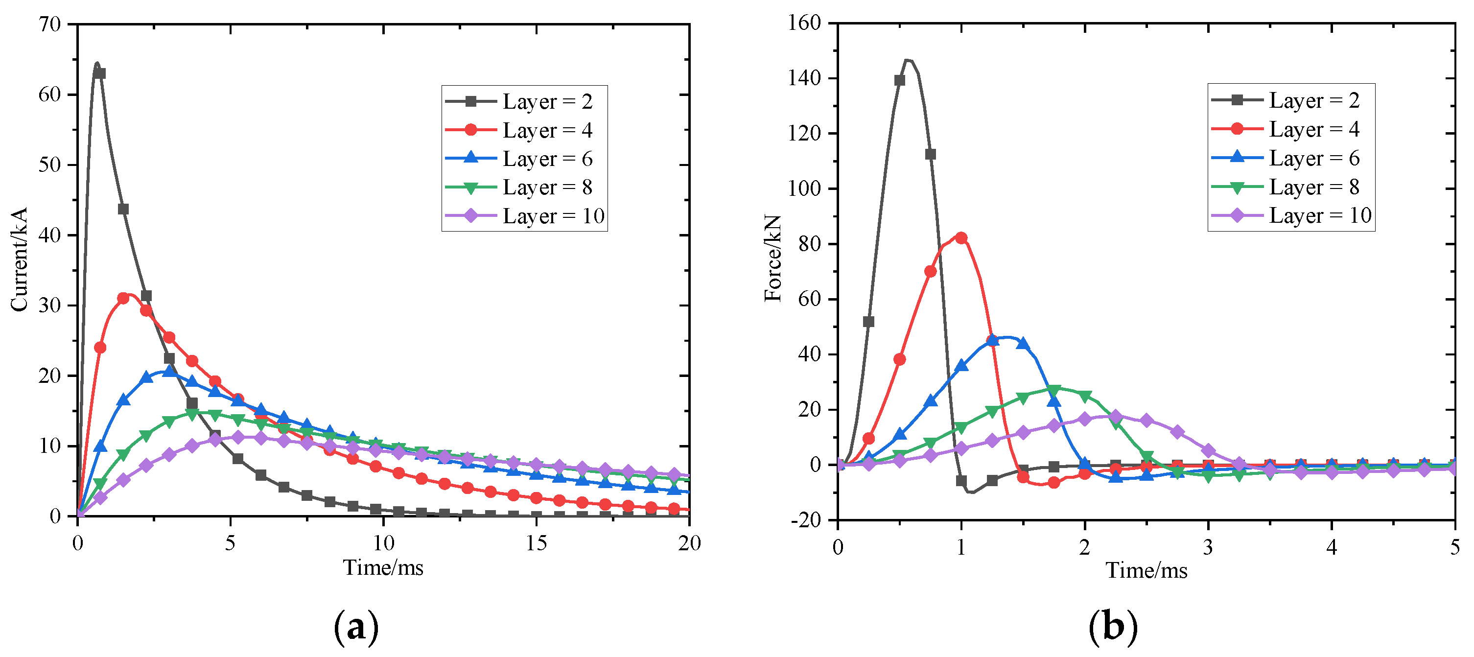
5.2. Influence of the Drive Coil Parameters on the Launch Performance

The structure of the drive coil is multi-turn winding in the axial and radial direction. Ideally, the length and width of the drive coil depend on the size of the wire and the number of axial and radial turns. In this section, the size of the wire is assumed to be constant, which is 10.2 mm × 8.75 mm, so the drive coil can be seen as a series of axial and radial coils. The resistance and inductance are calculated by numerical methods based on this assumption.
Firstly, the number of coils in series with the axial direction of the driving coil is taken to change in [1, 15] when the width of the driving coil is 4 turns, that is, the width is fixed at 35 mm. Table 3 shows the comparison of the muzzle velocity calculated by simulation for different numbers of coils.
It can be seen from Table 3 and Figure 12 that the muzzle velocity and energy conversion efficiency of the armature firstly increase and then decrease with the increase in the axial turns of the drive coil. The maximum muzzle velocity is 116.26 m/s, and the energy conversion efficiency is 5.07% when the number of axial turns of the drive coil is 4, that is, the length of the drive coil is 40.8 mm. Moreover, the increasing trend of the muzzle velocity and energy conversion efficiency gradually decreases with the increase in the length of the drive coil.
According to the principle of energy conservation, the energy obtained by the armature is equal to the integration of the force acting on the armature with time.
Figure 13 shows that the peak current of the drive coil and the peak force on the armature decrease when the axial length of the drive coil increases under the premise of the width of the drive coil remaining unchanged. The peak current and force are reduced, and the time to reach the peak value moves backward with the increase in the axial length. Therefore, there is an optimal value at which the ratio of the length of the drive coil to the internal radius is 2.44 and the muzzle velocity is the highest. The reason is that the number of axial turns of the drive coil increases with the increase in the length of the drive coil, so the resistance and inductance increase, and the average mutual inductance gradient between the drive coil and the armature decrease, which cause a decrease in the force.
Secondly, the layer of the drive coil is in series in the radial layer when the number of axial turns of the drive coil is 10 turns, that is, the length of the drive coil is 102 mm and the layer of the drive coil is changed in [1, 15]. Table 4 shows the muzzle velocity through the simulation.
It can be seen from Table 4 and Figure 14 that the muzzle velocity and energy conversion efficiency of the armature also firstly increase and then decrease with the increase in the layers of the drive coil. Under the current parameter conditions, when the number of series layers of the drive coil is two, namely, the width of the drive coil is 17.5 mm, the maximum muzzle velocity is 140.07 m/s and the maximum energy conversion efficiency is 7.36%. Moreover, the decreasing trend of the launch performance is a linear decrease with the increase in the width of the drive coil.
Figure 15 shows that the width of the drive coil increases, which causes the resistance to increase at the same time under the premise of the length of the driving coil remaining unchanged. The peak current of the drive coil and the peak force on the armature also decrease, and the time for the current and force to reach the peak value moves backward with the increase in the radial width. Therefore, there is also an optimal value for maximizing the area of the curve, that is, the muzzle velocity is the highest. The maximum value is obtained when the ratio of the width of the drive coil to the internal radius is 0.4. At the same time, the constraints of the wire current density and the maximum overload of the armature need to be considered.
The reason for the above results is that with the increase in the width of the drive coil, the number of turns of the drive coil increases and the resistance and inductance of the drive coil increase, resulting in a decrease in the magnetic coupling between the drive coil and the armature and a decrease in the mutual inductance and mutual inductance gradient.

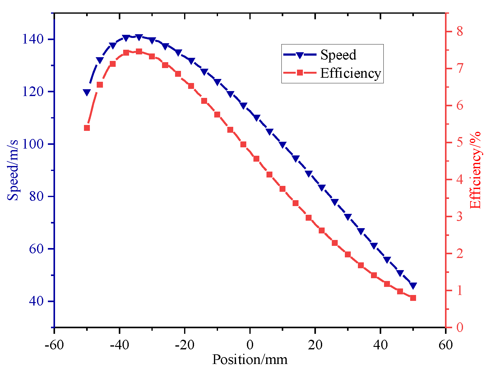
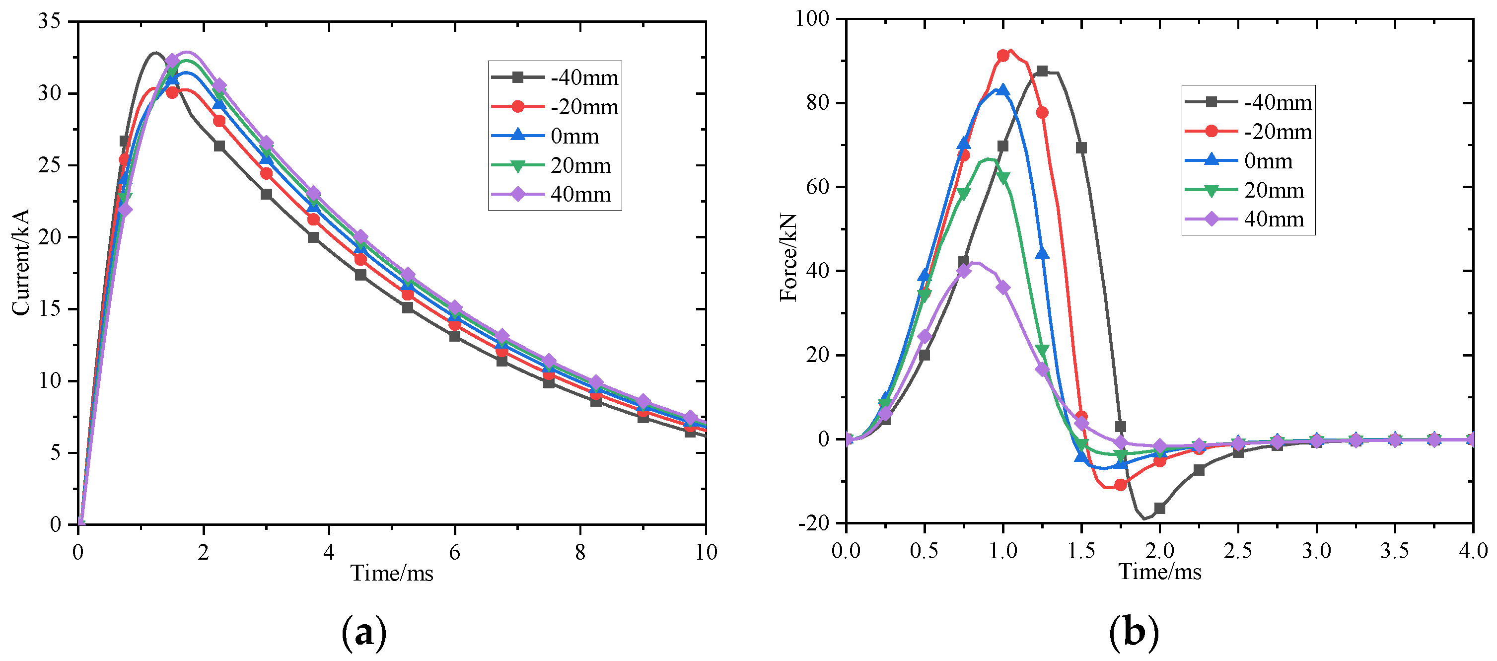
5.3. Influence of the Trigger Position on the Launch Performance

All the above analysis is based on the premise that the initial position of the armature means that the tail of it is in alignment with the center of the drive coil. For the single-stage EICL, the armature can accelerate in one direction when the center of the armature has passed through the center of the drive coil. If the initial position of the armature is different, the muzzle velocity is different. Therefore, a higher launch performance can only be obtained when the armature is in its optimal trigger position.
The drive coil structure size is selected so that the number of axial turns is 10 and the number of radial turns is 4, that is, the drive coil length is 102 mm and the width is 35 mm. The influence of the initial trigger position of the armature as a single variable on the launch performance is analyzed. It is assumed that the trigger position is 0 mm when the tail of the armature is located in the center of the drive coil, and the trigger position is considered to be positive when the armature moves in the direction of motion. The initial trigger position of the armature changes in [–50, 50] (mm). Figure 16 shows the launch performance obtained by simulation calculation.
It can be seen that the muzzle velocity of the armature firstly increases and then decreases with the change in the trigger position. The maximum muzzle velocity is 141.11 m/s and the energy conversion efficiency is 7.46% when the trigger position is −37 mm, that is, the initial position of the armature moves 37 mm from the center of the drive coil to the negative direction of motion.
Figure 17 shows the current and force at different trigger positions. It can be seen that changing the initial trigger position of the armature changes the length of the armature in the drive coil, and the peak current of the drive coil decreases with the movement of the armature in the direction of motion because the equivalent input impedance is different. When the armature moves in the direction of motion, the equivalent inductance between the drive coil and the armature increases, which causes a slow rise and slow attenuation of the drive coil current.
It can be seen from Figure 17 that the relationship between the force on the armature and the length of the armature located in the drive coil firstly increases and then decreases. According to the above analysis, there is also an optimal value for maximizing the muzzle velocity.

5.4. Influence of the Drive Coil Parameters and Trigger Position on the Launch Performance

According to the results of single-objective optimization analysis of the launcher structure parameters, it is difficult to obtain regular conclusions for single-objective optimization. Therefore, the length and width of the drive coil and trigger position are optimized simultaneously. The multi-objective values of the parameters are shown in Table 5.
It can be seen that there are total of 10 × 8 × 11 = 880 combinations in the multi-objective optimization. The simulation optimization analysis is carried out for each combination to obtain the corresponding launch performance under different combinations.
Figure 18 shows the results of multi-objective optimization analysis of the launch performance, where the x-y-z coordinates represent the width and length of the drive coil and trigger position. Cold and warm colors represent the magnitude of the muzzle velocity or energy conversion efficiency.
It can be seen that the higher launch performance is mainly concentrated where the length is increased, the width is small, and the trigger position is near the center. The increase in the drive coil length mainly increases the effective action time of the force on the armature. The decrease in the drive coil width mainly increases the equivalent mutual inductance and mutual inductance gradient between the drive coil and the armature. The trigger position near the center also increases the effective action time of the force on the armature. Therefore, the maximum muzzle velocity reaches 153.46 m/s and the energy conversion efficiency is 8.83% when the length of the drive coil is 9 turns, the width is 3 layers, and the trigger position is −30 mm.

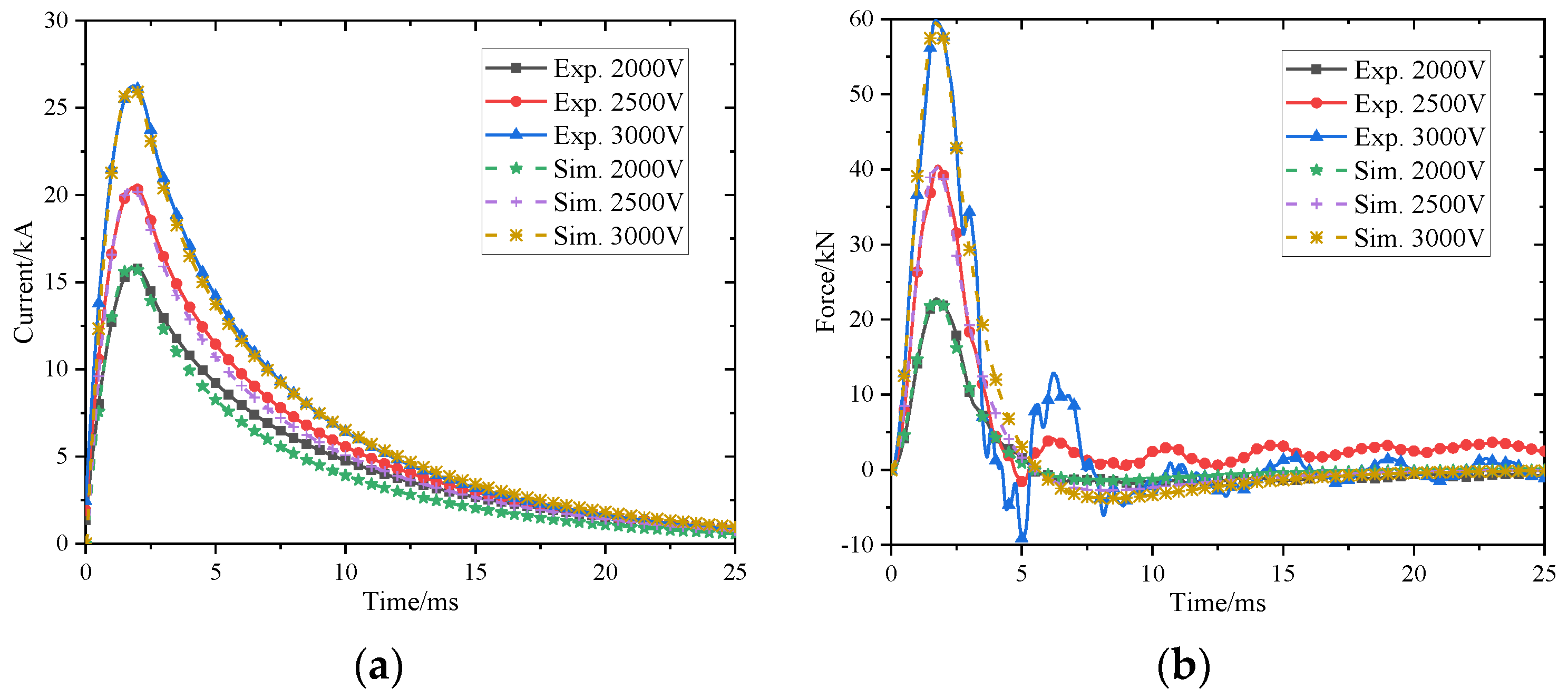
6. Experimental Verification

In order to validate the performance of the drive coil, it was necessary to carry out experimental research. The typical schematic of the discharge circuit is shown in Figure 19. According to the optimization results, the parameters of dynamic test equipment are shown in Table 6. The drive coil is connected to the pulse power supply by coaxial cable. Rl and Ll represent the resistance and inductance of the coaxial cable, respectively. Rd and Ld represent the resistance and inductance of the drive coil, respectively. The capacitor reverse charging is prevented by a diode D in parallel with the capacitor. The series resistance Rp reduces the rise time of the current through the diode.
Static and dynamic tests were carried out to obtain the force and muzzle velocity curves under the design parameters on the basis of the existing pulsed power supply in the laboratory. The experimental platform is shown in Figure 20. Two steel plates are installed on the base of this platform, one end is used to fix the drive coil and the other end is used to install the quartz pressure sensor. The static test can only verify the design rationality of the structure and electrical insulation of the drive coil, so it is necessary to carry out the dynamic test which includes locked-armature experiment and launch experiment.
In the locked-armature experiments, the armature was fixed inside the drive coil in order to measure the thrust force on the armature, and the tail of the armature was placed in the middle of the drive coil (z0 = 0 mm). The quartz pressure sensor was installed between the cylindrical armature and the base, and the bolt was tightened to ensure the force was uniform. The quartz pressure sensor signal was input into the data acquisition system through the matching amplifier. The fiber optical sensor system was used to measure the muzzle velocity. During the dynamic launch experiment, the muzzle velocity is calculated from the distance between the fiber optical sensors and the time that the armature passes through the fiber optical sensor. The distance between the two fiber optical sensors is 80 mm.
The simulation and dynamic test of different charging voltages were carried out on the drive coil. Firstly, Figure 21 shows the comparison results of the locked-armature experiment.
It can be seen from Figure 21 that the peak current is 15.92 kA, and the peak force on the armature is 22.75 kN when the charging voltage is 2 kV. When the charging voltage increases to 3 kV, the peak current increases to 26.25 kA, and the peak force increases to 59.83 kN. Due to the presence of the armature, the equivalent inductance between the drive coil and the armature is reduced, so the peak current and peak force would increase compared to the static test. The experimental results also verify the design of the mechanical strength and insulation of the drive coil. The force measured by the quartz pressure sensor is consistent with the simulation results.
The mass of armature which is made of aluminum is 0.54 kg, as shown in Figure 22. Table 7 shows the launch experimental results, which can be seen that the peak current is 33.71 kA and the energy conversion efficiency is 6.13% when the charging voltage is 2 kV, and when the charging voltage increases to 3 kV, the peak current increases to 54.59 kA and the energy conversion efficiency increases to 8.81%. Figure 23 shows the waveform of the fiber optical sensor with the charge voltage of 3 kV.
The correctness of the design and the model was verified. Therefore, we believe that it can be extended to the correctness of this paper.

7. Conclusions

This paper analyzed the influence of the change in the pulse power supply parameters and structural parameters on the launch performance of single-stage EICL, and several experiments on EICL were carried out. Some conclusions are drawn as follows:
(1)
There is an optimal value for the discharge voltage under the premise of the capacitance value of the capacitor bank remaining unchanged.
(2)
There is also an optimal value for the capacitance value under the premise of the discharge voltage of the capacitor bank remaining unchanged.
(3)
The optimal solution of the Pareto front was obtained for the current parameter conditions.
(4)
For the single-stage EICL, the larger the bore size, the higher the launch performance.
(5)
There is an optimal number of turns of the winding in the axial and radial direction of the drive coil and an optimal trigger position for the launch performance.

8. Recommendation

In the design of high-speed EICL, it is appropriate to choose capacitors with a smaller capacitance value and larger charging voltage to better match the armature launch state and thus obtain a better launch performance. Meanwhile, the drive coil parameters and bore size are two key structural factors affecting the launcher design, which should be considered in conjunction with the actual situation in the launcher design.

Author Contributions

Conceptualization, S.G. and X.G.; methodology, S.G.; software, B.W.; validation, J.S.; writing—original draft preparation, S.G.; writing—review and editing, X.G. All authors have read and agreed to the published version of the manuscript.

Funding

The authors would like to acknowledge National Natural Science Foundation of China (Grant No. 51777212) to X.G.

Data Availability Statement

Data available on request from the authors.

Acknowledgments

The authors wish to thank the reviewers for their careful, unbiased, and constructive suggestions, which led to this revised manuscript.

Conflicts of Interest

The authors declare no conflict of interest.

References

  1. Zhang, Y.; Xiong, M.; Gong, Y.; Xiao, G.; Niu, X.; Huang, D. Study on Multi-Segment Asynchronous Induction Coilgun Launcher. IEEE Trans. Plasma Sci. 2019, 47, 4700–4707. [Google Scholar] [CrossRef]
  2. Zhang, T.; Li, H.; Zhang, C.; Wang, Q.; Zhai, L.; An, Y.; Chen, Y. Design and Simulation of a Multimodule Superconducting Inductive Pulsed-Power Supply Model for a Railgun System. IEEE Trans. Plasma Sci. 2019, 47, 1352–1357. [Google Scholar] [CrossRef]
  3. Yang, W.; Yao, L.; Fu, Z. Simulation of Dynamic and Electromagnetic Characteristics of a Superconductor Bulk in a Single-Stage Induction Coilgun. IEEE Trans. Plasma Sci. 2019, 47, 821–827. [Google Scholar] [CrossRef]
  4. Engel, T.G.; Rada, N.M. Time- and Frequency-Domain Characterization of Railgun Sliding Contact Noise. IEEE Trans. Plasma Sci. 2017, 45, 1321–1326. [Google Scholar] [CrossRef]
  5. Engel, T.G.; Neri, J.M.; Veracka, M.J. Characterization of the Velocity Skin Effect in the Surface Layer of a Railgun Sliding Contact. IEEE Trans. Magn. 2008, 44, 1837–1844. [Google Scholar] [CrossRef]
  6. Becherini, G.; Tellini, A.; Tellini, B.D. Electromagnetic and mechanical gyro stabilization in railgun launcher. In Proceedings of the 2004 12th Symposium on Electromagnetic Launch Technology, Snowbird, UT, USA, 25–28 May 2004; pp. 32–36. [Google Scholar]
  7. Pokryvailo, A. To the theory of parallel railgun driven by an inductive storage power supply. In Proceedings of the Digest of Technical Papers. 12th IEEE International Pulsed Power Conference. (Cat. No.99CH36358), Monterey, CA, USA, 27–30 June 1999; Volume 2, pp. 1345–1348. [Google Scholar]
  8. Song, M.G.; Lee, Y.; Kim, H.M.; Le, D.V.; Go, B.S.; Park, M.; Yu, I.K. Development and Experimental Results of a Three-Stage Induction Coilgun. IEEE Trans. Plasma Sci. 2019, 47, 2438–2444. [Google Scholar] [CrossRef]
  9. Li, J.; Cao, R.; Li, S. The Development of EML Technology in China. IEEE Trans. Plasma Sci. 2013, 41, 1029–1033. [Google Scholar]
  10. Rezal, M.; Iqbal, S.J.; Hon, K.W. Development of Magnetic Pulsed Launcher System using Capacitor Banks. In Proceedings of the 2007 5th Student Conference on Research and Development, Selangor, Malaysia, 11–12 December 2007; pp. 1–4. [Google Scholar]
  11. Guan, X.; Wang, S.; Guan, S.; Guo, D.; Liu, B. Study on the Best Trigger Position of Multistage Induction Coil Launcher. IEEE Trans. Plasma Sci. 2019, 47, 2419–2423. [Google Scholar] [CrossRef]
  12. Chen, H.; Nie, R.; Zhao, W. A Novel Tubular Switched Reluctance Linear Launcher With a Module Stator. IEEE Trans. Plasma Sci. 2019, 47, 2539–2544. [Google Scholar] [CrossRef]
  13. Perotoni, M.B.; Mergl, M.; Bernardes, V.A. Coilgun Velocity Optimization With Current Switch Circuit. IEEE Trans. Plasma Sci. 2017, 45, 1015–1019. [Google Scholar] [CrossRef]
  14. Winarno, B.; Putra, R.G.; Yuwono, I.; Gunawan, A.I.; Sumantri, B. Control of Velocity Projectile on Multistage Coil gun. In Proceedings of the 2018 International Conference on Applied Science and Technology (iCAST), Manado, Indonesia, 26–27 October 2018; pp. 24–29. [Google Scholar]
  15. Zhang, Y.; Gong, Y.; Xiong, M.; Niu, X.; Xiao, G. Study of a Multisection Synchronous Induction Coil Launcher. IEEE Trans. Plasma Sci. 2018, 46, 2959–2964. [Google Scholar] [CrossRef]
  16. Song, M.G.; Le, D.V.; Go, B.S.; Park, M.; Yu, I.K. Design of an Attractive Force Circuit of Pulsed Power System for Multistage Synchronous Induction Coilgun. IEEE Trans. Plasma Sci. 2018, 46, 3606–3611. [Google Scholar] [CrossRef]
  17. Hu, Y.; Wang, Y.; Yan, Z.; Jiang, M.; Liang, L. Experiment and Analysis on the New Structure of the Coilgun With Stepped Coil Winding. IEEE Trans. Plasma Sci. 2018, 46, 2170–2174. [Google Scholar] [CrossRef]
  18. Xiao-Cun, G.; Song-Cheng, L.; Jun-Yong, L.; Zhou, R. The Launch Performance Analysis of the Electromagnetic Coil Launcher Continuous Launch Process With Multiple Armature. IEEE Trans. Plasma Sci. 2017, 45, 1519–1525. [Google Scholar] [CrossRef]
  19. Citak, H.; Ege, Y.; Coramik, M. Design and Optimization of Delphi-Based Electromagnetic Coilgun. IEEE Trans. Plasma Sci. 2019, 47, 2186–2196. [Google Scholar] [CrossRef]
  20. Mascolo, L.; Stoica, A. Electro-Magnetic Launchers on the Moon: A Feasibility Study. In Proceedings of the 2018 NASA/ESA Conference on Adaptive Hardware and Systems (AHS), Edinburgh, UK, 6–9 August 2018; pp. 37–42. [Google Scholar]
  21. Inger, E. Electromagnetic Launching Systems to Geosynchronously Equatorial Orbit in Space and Cost Calculations. IEEE Trans. Plasma Sci. 2017, 45, 1663–1666. [Google Scholar] [CrossRef]
  22. Rivas-Camacho, J.L.; Ponce-Silva, M.; Olivares-Peregrino, V.H. Experimental results concerning to the effects of the initial position of the projectile on the conversion efficiency of a reluctance accelerator. In Proceedings of the 2016 13th International Conference on Power Electronics (CIEP), Guanajuato, Mexico, 20–23 June 2016; pp. 92–97. [Google Scholar]
  23. Yang, D.; Liu, Z.; Li-jia, Y.; Zhi, S.; Jian-Ming, O.; Yan-Pan, H. Research on energy conversion efficiency of helical coil electromagnetic launcher. In Proceedings of the 2014 17th International Symposium on Electromagnetic Launch Technology, San Diego, CA, USA, 7–11 July 2014; pp. 1–5. [Google Scholar]
  24. Khatibzadeh, A.; Besmi, M.R. Improve dimension of projectile for increasing efficiency of electromagnetic launcher. In Proceedings of the 4th Annual International Power Electronics, Drive Systems and Technologies Conference, Tehran, Iran, 13–14 February 2013; pp. 55–59. [Google Scholar]
  25. Liu, W.; Cao, Y.; Zhang, Y.; Wang, J.; Yang, D. Parameters Optimization of Synchronous Induction Coilgun Based on Ant Colony Algorithm. IEEE Trans. Plasma Sci. 2011, 39, 100–104. [Google Scholar] [CrossRef]
  26. Guo, L.; Guo, N.; Wang, S.; Qiu, J.; Zhu, J.G.; Guo, Y.; Wang, Y. Optimization for capacitor-driven coilgun based on equivalent circuit model and genetic algorithm. In Proceedings of the 2009 IEEE Energy Conversion Congress and Exposition, San Jose, CA, USA, 20–24 September 2009; pp. 234–239. [Google Scholar]
  27. Seog-Whan, K.; Hyun-Kyo, J.; Song-Yop, H. An optimal design of capacitor-driven coilgun. IEEE Trans. Magn. 1994, 30, 207–211. [Google Scholar] [CrossRef]
  28. Seog-Whan, K.; Hyun-Kyo, J.; Song-Yop, H. Optimal design of multistage coilgun. IEEE Trans. Magn. 1996, 32, 505–508. [Google Scholar] [CrossRef]
  29. Lv, Q.A.; Li, Z.Y.; Lei, B.; Zhao, K.Y.; Zhang, Q.; Xiang, H.J.; Xie, S.S. Primary Structural Design and Optimal Armature Simulation for a Practical Electromagnetic Launcher. IEEE Trans. Plasma Sci. 2013, 41, 1403–1409. [Google Scholar]
  30. Zhang, Y.; Ruan, J.; Wang, Y.; Zhang, Y.; Liu, S. Armature Performance Comparison of an Induction Coil Launcher. IEEE Trans. Plasma Sci. 2011, 39, 471–475. [Google Scholar] [CrossRef]
  31. Dong, L.; Li, S.; Xie, H.; Zhang, Q.; Liu, J. Influence of Capacitor Parameters on Launch Performance of Multipole Field Reconnection Electromagnetic Launchers. IEEE Trans. Plasma Sci. 2018, 46, 2642–2646. [Google Scholar] [CrossRef]
  32. Abdo, T.M.; Elrefai, A.L.; Adly, A.A.; Mahgoub, O.A. Performance analysis of coil-gun electromagnetic launcher using a finite element coupled model. In Proceedings of the 2016 Eighteenth International Middle East Power Systems Conference (MEPCON), Cairo, Egypt, 27–29 December 2016; pp. 506–511. [Google Scholar]
  33. Li, X.; Wang, Q.L.; Wang, H.S.; Chen, S.Z.; Liu, J.H. Performance of a Four-Section Linear Induction Coil Launcher Prototype. IEEE Trans. Appl. Supercond. 2014, 24, 1–5. [Google Scholar] [CrossRef]
  34. Du, Z.; Liu, S.; Ruan, J.; Yao, Y.; Zhang, Y.; Huang, G.; Liao, C. Performance Analysis of a Coil Launcher Based on Improved CFM and Nonoverlapping Mortar FEM. IEEE Trans. Plasma Sci. 2013, 41, 1070–1076. [Google Scholar]
  35. Guan, S.; Wang, D.; Guan, X.; Li, W.; Gao, T.; Qiu, L. Coupling Analysis and Research of Multistage SICL Based on Crowbar Circuit. IEEE Trans. Plasma Sci. 2020, 48, 3211–3219. [Google Scholar] [CrossRef]
Figure 1. System parameters of EICL.
Energies 15 07803 g001
Figure 2. Change in the discharge voltage and its effect on the launch performance.
Energies 15 07803 g002
Figure 3. Current and force with the change in the discharge voltage. (a) Current of drive coil under different discharge voltages with constant capacitance of 16 mF; (b) Force on the armature under different discharge voltages with constant capacitance of 16 mF.
Energies 15 07803 g003
Figure 4. Change in the capacitance value and its effect on the launch performance.
Energies 15 07803 g004
Figure 5. Current and force with the change in the capacitance value. (a) Current of drive coil under different capacitance values with constant discharge voltage of 3 kV; (b) Force on the armature under different capacitance values with constant discharge voltage of 3 kV.
Energies 15 07803 g005
Figure 6. Change in the discharge voltage and capacitance value and its effect on the launch performance. (a) Muzzle velocity of armature under different discharge voltages and capacitance values; (b) Energy conversion efficiency of system under different discharge voltages and capacitance values.
Energies 15 07803 g006
Figure 7. Pareto front of the energy conversion efficiency. (a) Three-dimensional scatter of muzzle velocity and energy conversion efficiency under the combinations of different discharge voltages and capacitance values, red point is the combination of discharge voltage and capacitance value when energy conversion efficiency is maximum; (b) Projection of the three-dimensional scatter in the muzzle velocity and energy conversion efficiency coordinate plane.
Energies 15 07803 g007
Figure 8. Change in the bore size and its effect on the launch performance.
Energies 15 07803 g008
Figure 9. Current and force with the change in the bore size. (a) Current of drive coil under different bore size with constant unilateral air gap length of 4 mm; (b) Force on the armature under different bore size with constant unilateral air gap length of 4 mm.
Energies 15 07803 g009
Figure 10. Change in the unilateral air gap and its effect on the launch performance.
Energies 15 07803 g010
Figure 11. Current and force with the change in the unilateral air gap. (a) Current of drive coil under different unilateral air gap with constant armature outer diameter of 29.5 mm; (b) Force on the armature under different unilateral air gap with constant armature outer diameter of 29.5 mm.
Energies 15 07803 g011
Figure 12. Change in the number of axial turns and its effect on the launch performance.
Energies 15 07803 g012
Figure 13. Current and force with the change in the number of axial turns. (a) Current of drive coil under different axial length with constant the width of the drive coil of 35 mm; (b) Force on the armature under different axial length with constant the width of the drive coil of 35 mm.
Energies 15 07803 g013
Figure 14. Change in the number of radial layers and its effect on the launch performance.
Energies 15 07803 g014
Figure 15. Current and force with the change in the number of radial layers. (a) Current of drive coil under different width with constant the length of the drive coil of 102 mm; (b) Force on the armature under different width with constant the length of the drive coil of 102 mm.
Energies 15 07803 g015
Figure 16. Change in the trigger position and its effect on the launch performance.
Energies 15 07803 g016
Figure 17. Current and force with the change of trigger position. (a) Current of drive coil under different initial trigger position of the armature; (b) Force on the armature under different width with constant the length of the drive coil of 102 mm.
Energies 15 07803 g017
Figure 18. Simulation optimization results of the velocity and efficiency. (a) Muzzle velocity of armature under different length and width of the drive coil and trigger position, cold and warm colors represent the magnitude of the muzzle velocity; (b) Energy conversion efficiency of system under different length and width of the drive coil and trigger position, cold and warm colors represent the magnitude of the energy conversion efficiency.
Energies 15 07803 g018
Figure 19. Schematic of the discharged circuit, the * represents the eponymous end.
Energies 15 07803 g019
Figure 20. Dynamic test equipment. (a) Detailed composition photograph of thrust force measurement experimental; (b) Photograph of experimental results of data acquisition system.
Energies 15 07803 g020
Figure 21. Comparison of the simulation and experimental results. (a) Comparison of drive coil current between simulation calculation and experimental measurement; (b) Comparison of force on armature between simulation calculation and experimental measurement.
Energies 15 07803 g021
Figure 22. Armature for the dynamic test.
Energies 15 07803 g022
Figure 23. Muzzle velocity measurement system. (a) Detailed photograph of fiber optical sensor; (b) The waveform of the fiber optical sensors.
Energies 15 07803 g023
Table 1. Overview of the three launchers.
LauncherTechnical CharacteristicsResearch Status
RailSmall mass, hyper speed, sliding electrical contactWill be put into use
ReconnectionNon-contact, complex synchronous control technologyApplication of basic research
CoilNon-contact, large mass, high speedResearch on engineering development
Table 2. Parameters of the launchers.
ComponentUnitValue
ArmatureMaterialAluminum
Outer radiusmm29.5
Inner radiusmm23.5
Lengthmm200
Drive CoilsMaterialCopper
Inner radiusmm33.5
Outer radiusmm68.5
Lengthmm102
Turns 40
Table 3. Simulation results of the muzzle velocity with different axial turns.
Axial TurnsLength (mm)Length/Inner RadiusResistance (mΩ)Velocity (m/s)
110.20.3041.564.04
220.40.6093.0101.18
330.60.9134.5113.16
440.81.2186.0116.26
5511.5227.5116.24
661.21.8279.0116.02
771.42.13110.5115.29
881.62.43612.0114.23
991.82.74013.5113.41
101023.04515.0112.01
11112.23.34916.5111.87
12122.43.65418.0110.67
13132.63.95819.5109.95
14142.84.26321.0109.48
151534.56722.5108.23
Table 4. Simulation results of the muzzle velocity with different radial layers.
Radial LayersWidth (mm)Width/Inner RadiusResistance (mΩ)Velocity (m/s)
18.750.2613.75105.56
217.500.5227.50140.07
326.250.78411.25129.34
435.001.04515.00112.33
543.751.30618.7597.71
652.501.56722.5085.24
761.251.82826.2574.72
870.002.09030.0066.11
978.752.35133.7558.78
1087.502.61237.5052.66
1196.252.87341.2547.45
12105.003.13445.0042.88
13113.753.39648.7538.92
14122.503.65752.5035.44
15131.253.91856.2532.38
Table 5. Multi-objective values.
ObjectiveUnitValue
lengthturn1, 2, 3, 4, 5, 6, 7, 8, 9, 10
widthlayer1, 2, 3, 4, 5, 6, 7, 8
trigger positionmm−50, −40, −30, −20, −10, 0, 10, 20, 30, 40, 50
Table 6. Parameters for the dynamic test equipment.
ComponentUnitValue
ArmatureMaterialAluminum
Outer radiusmm29.5
Inner radiusmm23.5
Lengthmm200
Trigger Positionmm0
Drive CoilsMaterialCopper
Inner radiusmm33.5
widthmm26.25
Lengthmm91.8
Turns 27
Fiber Optical SensorDistancemm80
Numbers 4
Table 7. Launch experimental results.
No.Capacitance
/mF
Charge Voltage
/kV
Peak Current
/kA
Efficiency/%
1162.033.716.13
2162.544.897.80
3163.054.598.81
Publisher’s Note: MDPI stays neutral with regard to jurisdictional claims in published maps and institutional affiliations.

