Review

Characterization of Rotational Magnetic Properties of Amorphous Metal Materials for Advanced Electrical Machine Design and Analysis

1
Faculty of Engineering and Information Technology, University of Technology Sydney, Ultimo, NSW 2007, Australia
2
School of Engineering, Deakin University, Geelong, VIC 3216, Australia
3
School of Electrical and Information Engineering, The University of Sydney, Camperdown, NSW 2006, Australia
*
Authors to whom correspondence should be addressed.
Energies 2022, 15(20), 7798; https://doi.org/10.3390/en15207798
Submission received: 9 September 2022 / Revised: 6 October 2022 / Accepted: 17 October 2022 / Published: 21 October 2022
(This article belongs to the Special Issue Advanced Electrical Machine Design and Optimization)

Abstract

:
Amorphous metal (AM), specifically amorphous ferromagnetic metal, is considered as a satisfactory magnetic material for exploring electromagnetic devices with high-efficiency and high-power density, such as electrical machines and transformers, benefits from its various advantages, such as reasonably low power loss and very high permeability in medium to high frequency. However, the characteristics of these materials have not been investigated comprehensively, which limits its application prospects to good-performance electrical machines that have the magnetic flux density with generally rotational and non-sinusoidal features. The appropriate characterization of AMs under different magnetizations is among the fundamentals for utilizing these materials in electrical machines. This paper aims to extensively overview AM property measurement techniques in the presence of various magnetization patterns, particularly rotational magnetizations, and AM property modeling methods for advanced electrical machine design and analysis. Possible future research tasks are also discussed for further improving AM applications.

1. Introduction

Electrical machines play a key role in modern industry and domestic appliances. With the requirement of reducing the consumption of fossil fuels and the emissions of carbon oxide, it is expected that most electricity will be generated by renewable energy and most drives will be electric motors. For example, electric motors are replacing the traditional internal combustion engines in cars, buses, trains, ships and even aircraft [1,2,3,4,5,6]. The space and weight allowed in these vehicles are generally limited and they often operate with harsh conditions, such as high temperature and vibration. Therefore, one of the key issues for these applications is to investigate high-efficiency, high-power-density and high-reliability electric motors. For decades, researchers have been investigating various advanced electromagnetic materials for designing such high-performance electromagnetic devices, such as high-temperature superconductors [7,8], ultra-thin electrical steel sheets [9], soft magnetic composite [10,11,12] and amorphous metal (AM) materials, specifically the amorphous ferromagnetic metal [13,14,15,16,17,18,19,20,21,22,23,24,25]. Thanks to their advantageous properties of relatively low power losses at high frequency and very high saturation flux density, the AM materials appear to be excellent candidates as the core of high-power-density electromagnetic devices, such as high-speed electrical machines and high-frequency transformers.
AM materials, solid metallic materials and usually an alloy, have a disordered atomic-scale structure, which can also be called metallic glass and glassy metal. Amorphous ferromagnetic materials can be divided into several types based on their compositions, e.g., Fe-based, Ni-based and Co-based. Of these, the Fe-based types are commonly applied as machine cores thanks to their high saturation flux density and low cost. A number of companies supply the Fe-based AMs, such as Hitachi Metals Ltd., Japan, and Henan Zhongyuan Amorphous Technology Co. Ltd., China. Compared with traditional silicon steel, AM possesses the property of much lower power loss density, e.g., only about one tenth, making it an excellent candidate for high-frequency high-power-density electromagnetic devices. Furthermore, AM has reasonably high saturation magnetic flux density, e.g., much higher than that of ferrites commonly used in high-frequency transformers. Hence, AM magnetic devices can operate at reasonably high flux density and high frequency, leading to a small volume and high power density.
Therefore, AM has garnered strong interest as the core of high-efficiency, high-power-density electrical machines [13,14,15,16,17,18,19,20,21,22,23,24,25]. In 1982, Johnson et al. [13] investigated the application of low loss AM materials in electric motors and transformers. In 1989, Fukao et al. [14] used AM to build the stator and rotor cores of a super-high-speed reluctance motor. At 48,000 rpm, the core loss of the AM machine is 80% lower than that of its silicon iron counterpart. In 1992, Jensen et al. [15] proposed an axial-flux permanent magnet brushless DC motor, which has a tape-wound amorphous core and air-gap winding and shows the advantages of higher efficiency and lower costs compared to conventional machines. In 2008, Dehlinger et al. [16] compared the stator core losses of claw-pole transverse flux machines with amorphous core and iron steel cores. Results indicated that machine efficiency and speed range can be increased by using amorphous cores. In 2011, Wang et al. [17] developed a high-speed axial-gap ferrite permanent magnet motor with an AM stator, achieving an efficiency of 93% at 14,000 rpm.
In 2013, Kolano et al. [18] designed a high-speed radial-flux permanent magnet brushless DC motor with an AM stator made of a Metglas 2605 SA1 amorphous ribbon, achieving a much smaller power loss than the silicon steel stator. In 2014, Fan et al. [19] developed a high-power-density permanent magnet motor with AM stator, achieving a volume 31% smaller or power density 45% higher than that of a baseline motor. In 2015, Ertugrul et al. [20] reported a high-speed induction electrical machine with an AM stator iron core, which is formed by laminating 0.025 mm 1k101 strips to the desired thickness and then annealing, dipping and solidifying the processes. In 2016, Tang et al. [21] presented a review of the electrical machines with amorphous alloy cores and their key technologies, such as new topologies, processing, core losses and mechanical vibrations. In 2018, Simizu et al. [22] developed a compact, high-speed (high frequency of over 1 kHz), high-power motor by applying low-loss amorphous magnetic materials. The core loss is very low, e.g., smaller than 3 W at the rated power, while that of the silicon steel machine will exceed 90 W.
In 2019, Li et al. [23] presented the modeling and performance studies of high-speed synchronous reluctance motors considering the local effect of the AA core on the electromagnetic properties. In 2020, Ismagilov et al. [24] reported the design, performance analysis, prototyping and experiment of a high-speed permanent magnet generator with the stator made by amorphous magnetic material for aerospace applications. In 2021, Fan et al. [25] conducted the performance analysis and optimum design of a high-speed induction machine with an amorphous alloy iron core.
Although many achievements regarding developing AM electrical machines have been achieved, as in [13,14,15,16,17,18,19,20,21,22,23,24,25], the results are still far from the material’s potentials. One of the major reasons is the lack of appropriate property models based on proper mechanism understandings of the material. Almost all the property data and models used for designing the electrical machines are obtained under one-dimensional (1D) alternating magnetic excitation [26], and only a very small amount of work has been carried out for the AM properties under two-dimensional (2D) magnetization.
In the core of a rotating electrical motor or the T-joint of a three-phases transformer, the tip of magnetic flux density vector generally forms a 2D or even three-dimensional (3D) rotational irregular loop. It has been found that the magnetic material behaves very differently under the 1D alternating excitation and 2D/3D rotational excitation, and the conventional models cannot correctly predict the material properties under these irregular rotating flux density patterns [27,28,29,30,31,32,33,34].
In summary, for achieving the best use of material potentials, the AM property characteristics should be investigated under the actual conditions that electromagnetic devices usually operate in. This paper aims to present an overview of the characterization of AM materials under 2D rotational magnetizations based on the authors’ research as well as other scholars’ relevant work in this area.
The rest of this paper is organized as follows. Section 2 presents an overview of the AM magnetic property measurements based on 2D magnetic testing systems. Section 3 reviews the modeling of rotational magnetic properties, and Section 4 describes the application of the developed models in the advanced analysis of electrical machines. In Section 5, possible future research tasks on the advanced characterization of the AM material and its application for advanced electrical machine design and analysis devices are discussed.

2. Measurement of Rotational Magnetic Properties of Amorphous Magnetic Materials

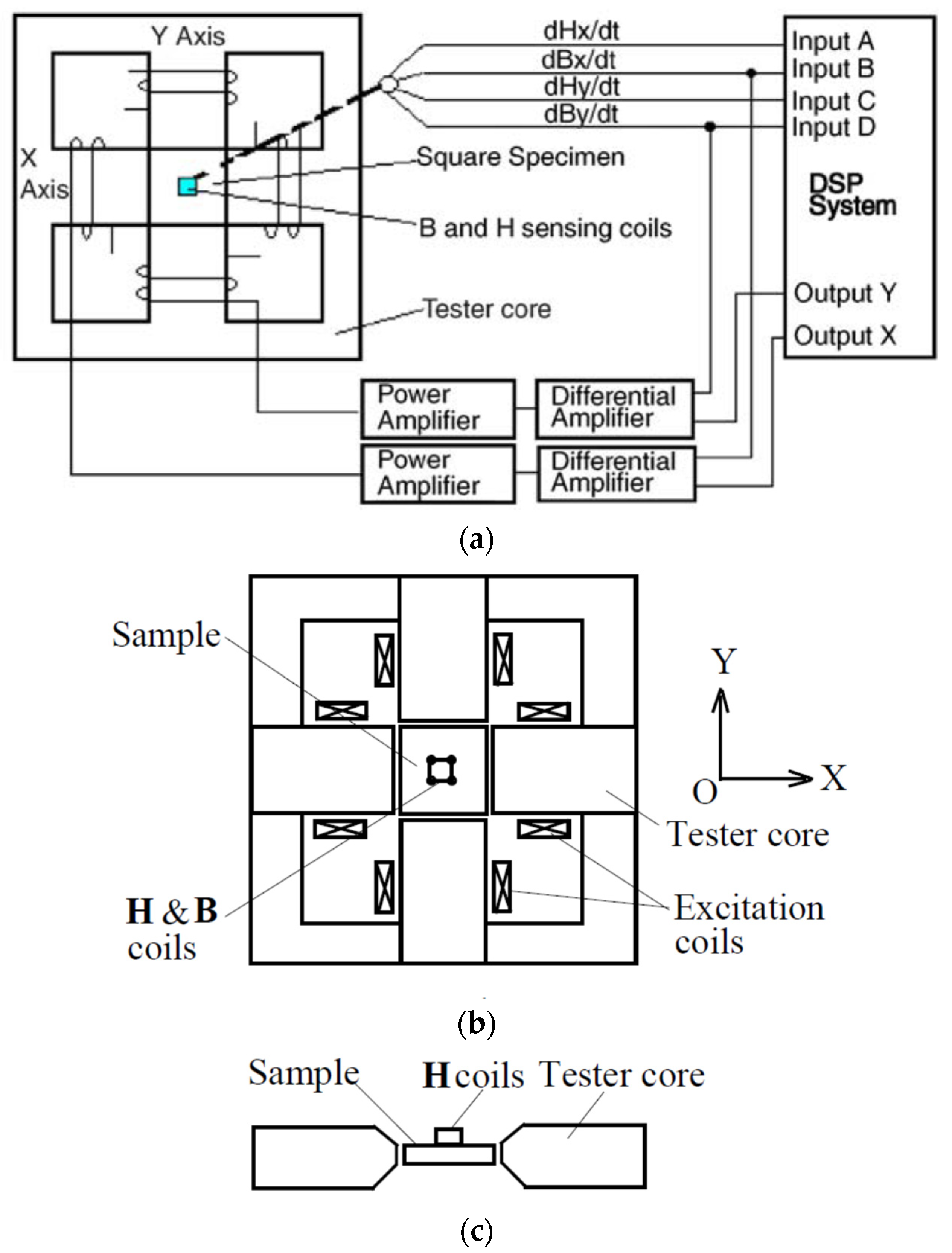
2.1. Measuring System of 2D Magnetic Properties

Since the first measurement of 2D rotational magnetic properties was reported by Baily in 1896 [27], a number of 2D rotational property measuring systems and techniques have been developed [28,29,30]. Of these measurement systems, the square sample single sheet tester, which was developed by Brix et al. [31], has proven to be the most favorable, thanks to its high control flexibility on rotating magnetic field patterns, outstanding uniformity of magnetic flux density distribution in the sample and, hence, high measurement accuracy.
Led by J. Zhu, the University of Technology Sydney (UTS) Magnetic Testing Group developed a square sample single sheet tester [32], which has been used to measure different magnetic materials. This tester is cooperated via a computerized digital signal process system, and it is able to measure the B-H relations as well as the core losses under 1D alternating fluxes in any specific direction, or 2D circularly and elliptical rotating fluxes with different axis ratios. Figure 1 shows the schematic diagram of the square single sheet tester and the whole system. The tester contains yokes made up of laminated grain-oriented electrical sheets, and the yoke shapes were designed to form four wedge-type magnetic poles. Two excitation coil groups are wound around the X- and Y-axes, and each group has two coils, which are connected in series. A square sample of magnetic material is installed in the middle of the tester.
The 2D magnetic field in the sample is produced with the currents flowing in the two sets of excitation coils discharged on X- and Y-axes, respectively. The excitation currents are provided by two power amplifiers. Through controlling the magnitudes, the phase angles and waveforms of the excitation currents, any 1D or 2D magnetic flux density vector can be produced, e.g., a 1D alternating flux density inclined at a specific angle from the X- or Y-axis, a circularly or elliptically rotational flux density or a flux density of any specified locus. Two dedicated differential amplifiers with low and high pass filters are used for the feedback control of the flux density components on the axes. The function generation and data acquisition are both realized by a PC-based digital signal processing system.

2.2. Material Sample for 2D Measurement

As shown in Figure 1, a square material sample is placed in the tester center, where a magnetic field is generated by the X- and Y-axes excitation currents. In our study [33], the sample was fabricated by cutting the AMCC-320 amorphous core, which is composed of amorphous 1k101 strips. The square sample is of 50 mm length, 50 mm width and 0.86 mm thickness and consists of an amorphous strip stack of 25 μm in thickness. The stacking factor is about 0.85.

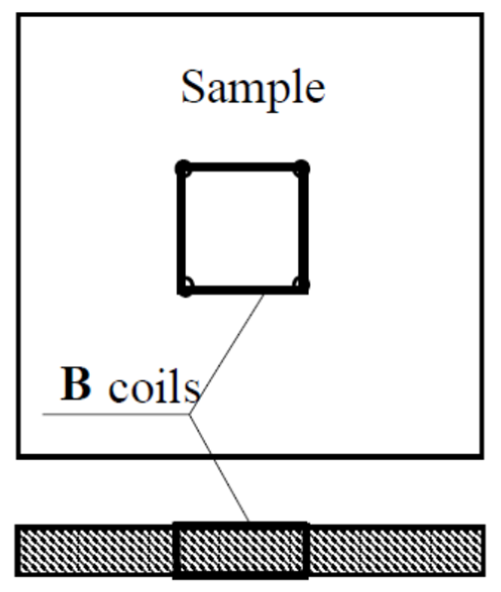
2.3. Measurement of 2D Magnetic Field

To acquire the B-H relation and associated core loss, the magnetic flux density inside the sample and the magnetic field strength on the surfaces should be measured accurately. As shown in Figure 1, the magnetic flux density and field strength in the sample can be acquired by the B and H sensing coils connected to the sample. Fifteen turns of enamel insulated copper wire of 0.1 mm in diameter are threaded through four small holes to form a B coil on each axis, as illustrated in Figure 2. The perforation is tiny and has little effect on the magnetic field distribution inside the sample. For accurate measurement, the flux density should be uniformly distribution in the sample, which is realized by optimal design of the tester, particularly the shape and dimensions of the magnetic poles.
The magnetic flux density on one axis can be computed by
B i = 1 N B i A B i V B i d t   ( i = x , y )
where ABi is the cross-sectional area, NBi is the turns number and VBi the induced voltage across the terminals of the B-coil on the axis.
The surface H coils, as shown in Figure 1c, are applied to measure the 2D magnetic field strength. According to the Ampere’s law, the field strength on the surface would be equal to that just inside the sample if there were no surface currents. The H-sensing coils can be fabricated very thinly, and they can be attached on the sample surface and thus the true value of the field strength inside the sample can be acquired. The magnetic field strength component on one axis can be computed by
H i = 1 μ 0 K H i V H i d t   ( i = x , y )
where VHi is the induced voltage across the terminals of the H-coil on the axis, μ0 the permeability of air and KHi the coil coefficient, which is determined by calibrating a solenoid as shown in Figure 3, where A is the frame, B is the H coils to be calibrated, C is the Gauss meter probe, D is the connector for outputting the coil terminal voltage signals, E is the turn table for placing the coils and F and G are the wheel rubber bands for adjusting the coil orientation.
It should be noted that this tester can also be used to measure the 1D alternating magnetic properties. When only the X-axis or Y-axis excitation current is applied, the H and B vectors are constrained in the X or Y direction, and the measured B-H relation would be the traditional B-H hysteresis loops.
The measurement of rotational magnetic properties is mainly conducted under the so-called circularly rotating magnetization, i.e., the excitation currents of the X- and Y- axes are controlled to form a rotating flux density vector of constant magnitude and speed. Sometimes, measurements under elliptically rotating magnetization are also carried out, e.g., with different ratios of the minor-axis to major-axis magnitudes of flux density. The magnetic properties are usually measured with various frequencies and various maximum flux densities.

2.4. Measurement of Rotational Core Loss

After the flux density and field strength of the sample are measured, the total core loss Pt can therefore be calculated with Poynting’s theorem:
P t = 1 T ρ m 0 T H · d B d t d t = 1 T ρ m 0 T ( H x · d B x d t + H y · d B y d t ) d t
where ρm the mass density of the sample material, T is the time period and Hx, Hy, Bx and By are, respectively, the X and Y components of H and B.

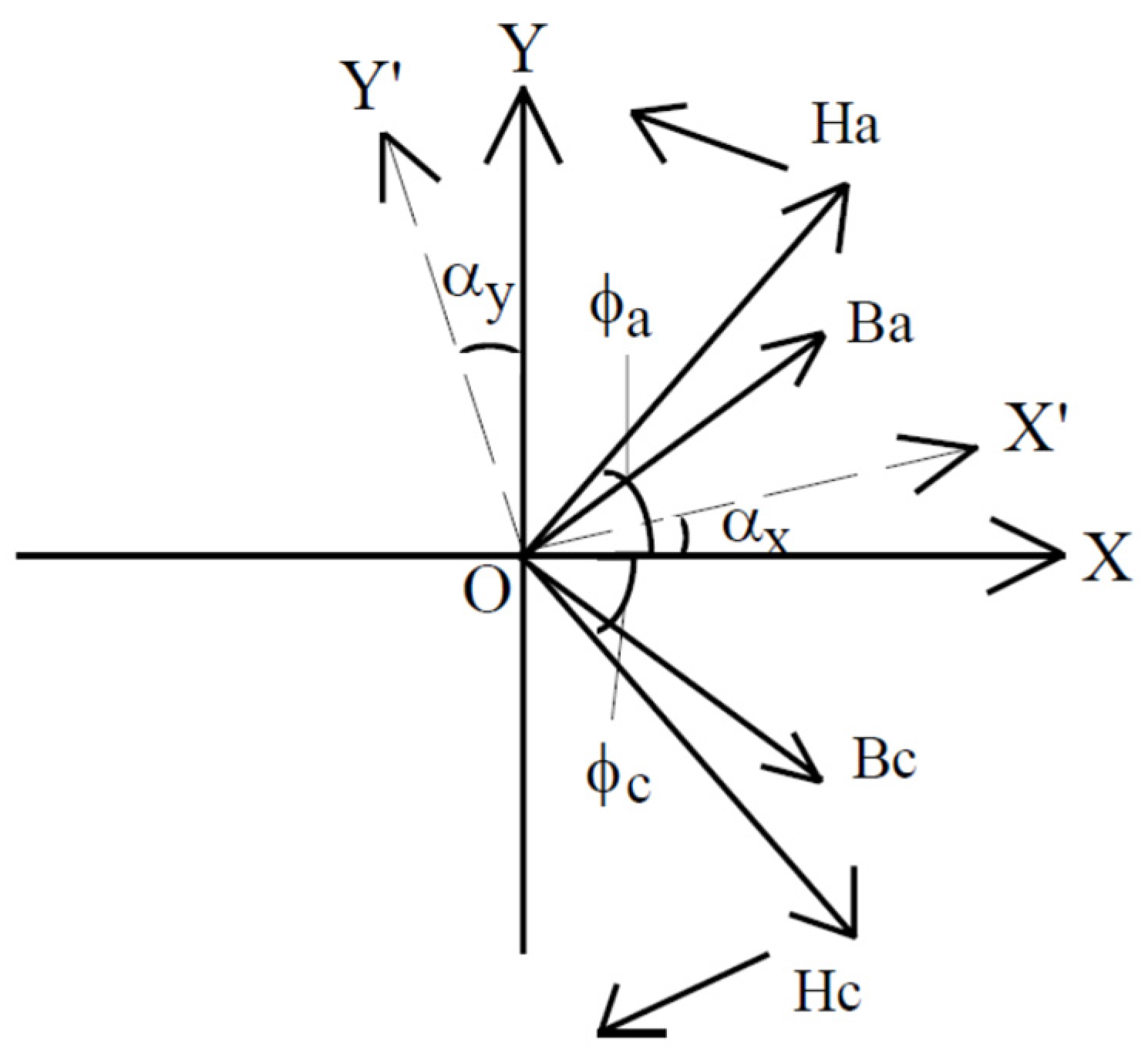
2.5. Correction of Sensing Coil Misalighnment

A slight misalignment of the H-sensing coil with the excitation coil axis may cause a significant error of measured values. If the misalignment angles are known, the true values can be obtained by
( H x H y ) = 1 | C | ( cos α y sin α x sin α y cos α x )   ( H x H y )
where Hx and Hy are the true values, Hx′ and Hy′ are the measured values, αx and αy are the misalignment angles from X and Y axes and |C| = cosαx cosαy + sinαx sinαy.
To identify the misalignment angles, a measurement of both the X-axis and Y-axis coils under 1D excitation is carried out. When only the X-axis coil is excited, the Y-axis component is Hy = 0 and we can obtain
A x = H x H y = cos α x sin α y
When only the Y-axis coil is excited, the X-axis component is Hx = 0 and we can obtain
A y = H x H y = sin α x cos α y
The misalignment angles can be worked out by simultaneously solving (5) and (6):
α x = arccos ( ± A x 1 A y 2 A x 2 A y 2 ) , α y = arccos ( ± A x 2 1 A x 2 A y 2 )
As to the B coils, there is no need to transform as the magnetic flux density is a controlled vector and the B coils can be accurately fixed along the X- or Y-axis.

2.6. Correction of 2D Mesaurement with Rotating Excitations

It is found that there might be difference between the 2D measurement under clockwise and anti-clockwise rotating fluxes, which may be caused by the H sensor misalignment and the device asymmetry [34,35]. To solve this problem, an averaging method is applied by averaging the measured H loci and power losses in two directions.

2.6.1. Correction of H Loci

Figure 4 illustrates two controlled flux density vectors Bc and Ba in the clockwise and anticlockwise directions, where the actual misalignments of Hx and Hy coils are marked as αx and αy, respectively.
The clockwise 2D rotating field strength is marked as Ha with its X and Y components as Hx and Hy. Then, the measured field strength components in the X’OY’ coordinate are
{ H a x = H x cos α x + H y sin α x H a y = H x sin α y + H y cos α y
Similarly, the anticlockwise 2D rotating field strength is marked as Hc, and the misalignment angles of the Hx and Hy coils would be −αx and −αy, respectively. Then, the measured field strength components in the X’OY’ coordinate can be expressed as
{ H c x = H x cos α x H y sin α x H c y = H x sin α y + H y cos α y
By adding (8) and (9), one can obtain
{ H a x + H c x = 2 H x cos α x H a y + H c y = 2 H y cos α y
For a slight alignment, i.e., small αx and αy, one can obtain the following expressions
{ H x H a x + H c x 2 H y H a y + H c y 2

2.6.2. Correction of Rotational Core Losses

Sequentially, the rotational core losses can also be corrected using the averaging method. Substituting (11) into (3), one has
P t = 1 T ρ m 0 T ( H x d B x d t + H y d B y d t ) d t = 1 T ρ m 0 T ( H a x + H c x 2 d B x d t + H a y + H c y 2 d B y d t ) d t = 1 2 T ρ m ( 0 T ( H a x d B x d t + H a y d B y d t ) d t + 0 T ( H c x d B x d t + H c y d B y d t ) d t ) = P t a + P t c 2
where Pta and Ptc are, respectively, the measured core losses under the anticlockwise and clockwise rotating fluxes. The correct core loss under rotating magnetization can be expressed approximately as the average of the measured core losses under anticlockwise and clockwise directions.

2.7. 2D Mesaurement of the Fe-Based Amorphous Metal Materials with Rotating Excitations

Based on the above-mentioned 2D magnetic measuring systems and techniques, a Fe-based amorphous magnetic material, Zhongyue amorphous metal 1k101, has been investigated under 2D rotational magnetization [33]. As an example, the measurements were carried out under the rotational magnetization of 50 Hz and various flux densities. As shown in Figure 5, the B loci were controlled so that they rotate circularly with the same magnitude, where the magnitude of H loci varies due to the nonlinear property of the amorphous material. Furthermore, it can be seen that the maximum values of Hx and Hy are not quite the same, revealing the slight anisotropy of the material. By using (3), the corresponding core losses can be worked out.

3. Modeling of Rotational Magnetic Properties

3.1. Modeling of B-H Relations under Rotational Magnetization

For the magnetic properties under the 1D alternating magnetism, the B-H relations are a series of hysteresis loops, which are usually simplified to nonlinear curves for the electrical machine design, i.e., the single-valued B-H curve is usually used in the magnetic field analysis. However, the B-H relations are multi-valued loops, i.e., two or more B values are possible for certain H, depending on the magnetization history. Furthermore, as discussed above, the magnetic fields in electrical machine cores are generally vectorial, so the magnetization process of magnetic materials should be considered using vector magnetization [36]. The commonly used modeling methods include the vectorial Preisach model [37,38,39,40], Stoner–Wohlfarth model [41,42,43,44], combined model [45,46], Jiles–Atherton Model [47,48], and E&S model [49,50].
These models can simulate the B-H relations in the magnetic materials with good accuracy, but their applications in practical electromagnetic devices are still challenging, e.g., how to implement them in the Maxwell Equations to solve the B and H distributions. Due to the rotational magnetization, the magnetic material’s permeability or reluctivity becomes a full 3D tensor with both diagonal and off-diagonal terms or a full 2D tensor if the 2D magnetic field analysis is conducted [51,52,53,54]. There is generally a phase difference between H and B, so the constitutive equation should be expressed by
H i = j v i j B j
where i,j = x,y,z in the rectangular coordinate or i,j = r,θ,z in the cylindrical coordinate, and νij is the reluctivity tensor. Taking the static magnetic field analysis as an example, the following curl–curl equation is derived from Maxwell’s equations:
× ( v × A ) = J 0
where A is the magnetic vector potential, ν is the reluctivity tensor and J0 is the applied current density vector. In the rectangular coordinate, the equation for the x-component of J0 can be transformed into the following component form, and the equations for Jy and Jz can be derived in a similar way.
y [ v z x ( A z y A y z ) + v z y ( A x z A z x ) + v z z ( A y x A x y ) ] z [ v y x ( A z y A y z ) + v y y ( A x z A z x ) + v y z ( A y x A x y ) ] = J x

3.2. Modeling of Core Losse under Rotational Magnetization

It has been found from measuring various magnetic materials that the core loss under rotational magnetization is very different from that under alternating magnetization. As an example, Figure 6 shows the measurement of the core loss of a soft magnetic composite sample under the alternating and purely rotational flux densities of different peak values and frequencies [55].
It can be seen that the rotational core losses under two cases behave very differently. The similar phenomena might also be true for AM. Figure 7 shows the measured alternating and rotational core losses of an amorphous magnetic metal sample 1k101 [33].
It can be seen from Figure 6 and Figure 7 that at low to mid-range flux density, the rotational core loss approximately equals double of its alternating counterpart. At the saturation level, however, the rotational core loss decreases quickly to the level well below the alternating core loss, which continues to increase with the rising flux density. Therefore, new and proper models should be investigated to calculate the core loss.
By imitating the alternating core loss, Pa, the rotational core loss, Pr, is also separated into three terms: rotational hysteresis loss, rotational eddy current loss and rotational anomalous loss [56] and the formulae can be expressed below [57]:
P a = C h a f B P h + C e a ( f B P ) 2 + C a a ( f B P ) 1.5
P r = P h r + C e r ( f B P ) 2 + C a r ( f B P ) 1.5
where f and BP are, respectively, the frequency and peak value of flux density and h, Cha, Cea, Caa, Cer and Car are the core loss coefficients, which can be determined by curve-fitting the experimental results on the material sample. The major difference is with the hysteresis loss. The ratio of the rotational hysteresis loss to its alternating counterpart at low to mid-range flux density is between 1 and 2 for different materials, as reported by different researchers. However, the rotational hysteresis loss decreases quickly at the saturation level, whereas the alternating hysteresis loss continues to rise.
Bertotti et al. used the three-term model to calculate the core loss in an induction motor [58]. For the hysteresis with elliptically rotating flux density, a linear interpolation between alternating and circularly rotational losses was employed and the calculation was around 20% lower than the measurement.
Zhu and Ramsden proposed a formulation to model the rotational hysteresis loss based on the similarity between the curve of Phr versus B and that of the torque versus slip of a single-phase induction machine [59]:
P h r f = a 1 [ 1 / s ( a 2 + 1 / s ) 2 + a 3 2 1 / ( 2 s ) [ a 2 + 1 / ( 2 s ) ] 2 + a 3 2 ]
s = 1 B B s 1 1 a 2 2 + a 3 2
where Bs is the saturation flux density and a1, a2 and a3 are all the coefficients that can be determined by curve-fitting the measured data of the material sample. The formulation was used to calculate the core loss of a permanent magnet motor and the error was reduced to about 10%.
A further modification is developed based on the curve of the electromagnetic power versus slip of a three-phase induction motor [33].
P h r f = b 1 ( 1 s ) s [ ( b 2 s + 1 ) 2 + b 3 s 2 ]
s = 1 B m B s
where Bm is the magnitude of flux density and b1, b2 and b3 are all the core loss coefficients. This modified formulation has been used to model the core loss of the amorphous 1k101 sample, and the error was much reduced compared to the existing analogical model and alternating loss-based model, respectively.

4. Application of Rotational Magnetic Properties for Electrical Machine Analysis

Although a large number of models have been developed for describing the rotational magnetic properties of magnetic materials, the application of the developed models in the electrical machine analysis is still difficult. Considering that the major difference is the core loss, a number of works have been conducted regarding the calculation of rotational core loss based on the conventional magnetic field analysis, i.e., the B-H relation of magnetic material is a single-valued curve.
Based on the Zhu’s model [59], the UTS group designed a few electric motors with soft magnetic composite cores [57,60,61,62]. According to [63], in order to calculate the motor core loss under any situation, it might be sufficient to have the sample data under 1D alternating sinusoidal and 2D purely circular flux densities, as shown in Figure 5. Firstly, the flux density locus at any point (element) is computed by using the 3D time-stepping finite element analysis (FEA). For various rotor positions, e.g., every 10 electrical degrees, the FEA is conducted for 360 electrical degrees, i.e., two pole-pitches to obtain the flux density locus, which should be an irregular loop in 3D space generally. The well-known 1D alternating sinusoidal and 2D purely or elliptically rotating flux density patterns can be considered as the special cases of the 3D loop.
The flux density locus is a periodic function of time with a period where the rotor rotates by 360 electrical degrees and thus its three components projected to the three axes, e.g., Br, Bθ and Bz in the cylindrical coordinate, will also be functions of time. By using Fourier series expansion, the three components can be expressed as
{ B r ( t ) = k = 0 [ B r s k sin ( 2 π k f s t ) + B r c k cos ( 2 π k f s t ) ] B θ ( t ) = k = 0 [ B θ s k sin ( 2 π k f s t ) + B θ c k cos ( 2 π k f s t ) ] B z ( t ) = k = 0 [ B z s k sin ( 2 π k f s t ) + B z c k cos ( 2 π k f s t ) ]
where k is the order of the harmonic and fs is the frequency of the fundamental component of flux density. For the harmonic of any order, the following two parts are obtained:
{ B s k = n s k B r s k 2 + B θ s k 2 + B z s k 2 sin ( 2 π k f s t ) B c k = n c k B r c k 2 + B θ c k 2 + B z c k 2 cos ( 2 π k f s t )
The two unit vectors, nsk and nck, are perpendicular to each other, and they can be determined by
{ n s k = B r s k r + B θ s k θ + B z s k z B r s k 2 + B θ s k 2 + B z s k 2 n c k = B r c k r + B θ c k θ + B z c k z B r c k 2 + B θ c k 2 + B z c k 2
The two vectors in (23) will form an elliptical trajectory on a plane, which may not be parallel to any coordinate axis. The major axis Bkmaj of the k-th harmonic depends on the larger of |Bsk| and |Bck|, while the minor axis Bkmin is the smaller of |Bsk| and |Bck|. The elliptically rotational core loss can be computed by the measured alternating loss and circularly rotational loss at the same frequency as [64]
P k = P r k R B K + ( 1 R B K ) 2 P a k
where Prk is the circularly rotational loss with flux density Bkmaj, RBK = Bkmin/Bkmaj is the axis ratio of the k-th B harmonic and Pak is the alternating loss with flux density magnitude of Bkmaj.
To find out the total loss of all the harmonics, Poynting’s theorem is applied.
P t = 1 T ρ m 0 T H · d B d t d t = 1 T ρ m 0 T ( H r d B r d t + H θ d B θ d t + H z d B z d t ) d t
Similar to (22), the H locus can also be expanded into Fourier series as
H i ( t ) = k = 0 [ H i s k sin ( 2 π k f t ) + H i c k cos ( 2 π k f t ) ]
where i = r, θ or z and k = 0 corresponds to the zero-order harmonic (i.e., the constant component), which does not produce any core loss. For any k (or m) = 1, 2, 3…
0 T ( H i d B i d t ) d t = 0 T k = 1 ( [ H i s k sin ( 2 π k f t ) + H i c k cos ( 2 π k f t ) ] d m = 1 [ B i s m sin ( 2 π m f t ) + B i c m cos ( 2 π m f t ) ] d t ) d t = 0 T ( k = 1 [ H i s k sin ( 2 π k f t ) + H i c k cos ( 2 π k f t ) ] ) ( m = 1 2 π m f [ B i s m cos ( 2 π m f t ) B i c m sin ( 2 π m f t ) ] ) d t
When k and m are not equal, the integration always becomes 0, i.e., the combination of harmonics of Bi(i = r, θ, or z) and Hi with different orders does not produce any magnetic power loss.
When k = m (=1, 2, 3…)
0 T ( k = 1 [ H i s k sin ( 2 π k f t ) + H i c k cos ( 2 π k f t ) ] ) ( m = 1 2 π m f [ B i s m cos ( 2 π m f t ) B i c m sin ( 2 π m f t ) ] ) d t = 0 T ( k = 1 [ H i s k sin ( 2 π k f t ) + H i c k cos ( 2 π k f t ) ] ) ( k = 1 2 π k f [ B i s k cos ( 2 π k f t ) B i c k sin ( 2 π k f t ) ] ) d t = k = 1 0 T ( [ H i s k sin ( 2 π k f t ) + H i c k cos ( 2 π k f t ) ] 2 π k f [ B i s k cos ( 2 π k f t ) B i c k sin ( 2 π k f t ) ] ) d t = k = 1 0 T ( H i k d B i k d t ) d t
then (26) becomes
P t = 1 T ρ m 0 T ( H r d B r d t + H θ d B θ d t + H z d B z d t ) d t = 1 T ρ m k = 1 0 T ( H r k d B r k d t + H θ k d B θ k d t + H z k d B z k d t ) d t
Therefore, the total loss in one element can be obtained by simply summing up the contributions of all the harmonics, and the total machine core loss is
P t = e = 1 N e k = 0 [ P r k R B K + ( 1 R B K ) 2 P a k ]
where Ne is the number of FEA elements of the magnetic core.
The above-mentioned procedure has been applied to calculate the core loss of a few SMC motor prototypes and an example was described in [63]. Firstly, the flux density locus in each element of the motor core was worked out by using 3D time-stepping magnetic field finite element analysis. By using (22)–(31), the core loss of the prototype motor was calculated as 59.2 W at a rated speed, which agrees well with the measured 61.0 W. The calculations and measurements at other speeds were all within 5% error.

5. Conclusions and Future Directions

This paper has presented an overview regarding the measurement and modeling of the rotational magnetic properties of AM materials, specifically the amorphous ferromagnetic metals and the advanced design and analysis of AM electrical machines by using the developed models. Some promising results have been achieved, but there are still many challenging tasks that should be investigated.

5.1. Standard and Systematic Measurement of AM Properties under Rotational Magnetization

Although the rotational properties of magnetic materials are considered crucial for designing high-performance electrical machines, all manufacturers provide only the 1D alternating data. The testing system and measuring procedure are quite complicated and only a few research groups are capable of conducting such measurements. To the best knowledge of the authors, very little work has been carried out on the measurement of AM rotational magnetic properties. In 1992, Enokizono et al. [65] investigated the 2D magnetic properties of an amorphous sheet under a rotating magnetic field. In 2011, Ueno et al. [66] reported the measurement of 2D vector magnetic properties of a FeSiB amorphous sheet. In 2021, the authors of this paper [33] presented the rotational core loss measurement and the modeling of a Fe-based amorphous magnetic material.
There is no standard yet on the measurement of rotational magnetic properties. It has been discussed by experts, e.g., during the International Workshops on 1 & 2 Dimensional Magnetic Measurement and Testing, in terms of building a proper measurement standard, which would be practical for material manufacturers to test the materials. It would be desirable for users to obtain the complete magnetic properties of magnetic materials supplied, e.g., B-H loci, and associate core losses under rotating B vectors of various magnitudes and frequencies over the operation ranges.

5.2. Appropriate Modeling of Rotational Magnetic Properties

Although a few rotational magnetic property models have been developed, they are generally too complicated to be implemented in the magnetic field analysis. The magnetic field strength H and flux density B have a multi-valued relationship, so historical information is needed to predict one from the other.
To develop more effective models, an in-depth understanding about the magnetization mechanism based on extensive theoretical and experimental studies on AM samples under rotating magnetic fluxes is expected to be necessary. By comprehensively analyzing the measurement data, a set of hypotheses will be proposed to support the deep understanding of the physical mechanism under different flux density vector (B) patterns. Artificial intelligence techniques, such as machine learning and neural networks, might be helpful for developing engineering application oriented models.

5.3. Dynamic Modeling Considering the Effects of Multi-Factors on Magnetic Properties

The core loss is also affected by many other factors, such as temperature and mechanical stress [67,68]. To accurately predict the core loss in an electrical machine, the rotational magnetic properties of AM materials should also be investigated under different temperatures and mechanical stresses within the operational ranges. Then, a dynamic core loss model can be built, which is relevant to multi-factors, such as the flux density patterns, harmonics, magnitudes and frequency, as well as machine temperature and mechanical stress [69]. Based on the digital twin technology, the dynamic model can predict the core loss during the machine operation, e.g., the effects of temperature rise and load current with respect to running time [70].

5.4. Magnetic Properties under 3D Rotational Magnetization

The magnetic field in the core of an electrical machine is naturally 3D, e.g., the B and H vectors are irregular loops in 3D space. This is particularly true for the so-called 3D magnetic flux electrical machines, such as the claw pole and transverse flux machines [71]. Even with 1D alternating or 2D rotating magnetization, the magnetic material may exhibit a 3D magnetic property due to the magnetic domain walls motion and the magnetization rotation [72]. This phenomenon has been found for SMC materials, but it might also occur in AM materials and should be investigated. It appears that only the 3D vector magnetic properties are the most natural for thoroughly understanding and modeling the magnetization process. However, the 3D testing system is only available at a couple of research groups [72,73]. The measurement process is quite complicated, and which typical patterns of magnetic properties should be measured has not been well-defined.

Author Contributions

Conceptualization, L.L. and Y.G.; methodology, L.L., Y.G. and X.B.; software, L.L., X.B. and G.L.; validation, L.L., Y.G. and G.L.; formal analysis, H.L. and J.Z.; investigation, L.L. and Y.G.; resources, Y.G., P.S. and J.Z.; data curation, L.L. and X.B.; writing—original draft preparation, Y.G. and L.L.; writing—review and editing, X.B., H.L., G.L., P.S. and J.Z.; visualization, L.L. and H.L.; supervision, Y.G., G.L., P.S. and J.Z.; project administration, Y.G., H.L., G.L. and J.Z.; funding acquisition, Y.G., H.L., G.L., P.S. and J.Z. All authors have read and agreed to the published version of the manuscript.

Funding

This research was funded by the Australian Research Council under Discovery Grant DP120104305 and DP180100470, and the Foundation of China Scholarship Council under Grant 201906730038.

Data Availability Statement

Not applicable.

Conflicts of Interest

The authors declare no conflict of interest.

References

  1. Zhu, Z.Q.; Howe, D. Electrical Machines and Drives for Electric, Hybrid, and Fuel Cell Vehicles. Proc. IEEE 2007, 95, 746–765. [Google Scholar] [CrossRef]
  2. Sun, X.; Shi, Z.; Lei, G.; Guo, Y.; Zhu, J. Analysis and Design Optimization of a Permanent Magnet Synchronous Motor for a Campus Patrol Electric Vehicle. IEEE Trans. Veh. Technol. 2019, 68, 10535–10544. [Google Scholar] [CrossRef]
  3. Ritari, A.; Vepsäläinen, J.; Kivekäs, K.; Tammi, K.; Laitinen, H. Energy Consumption and Lifecycle Cost Analysis of Electric City Buses with Multispeed Gearboxes. Energies 2020, 13, 2117. [Google Scholar] [CrossRef]
  4. Guo, Y.G.; Jin, J.X.; Zhu, J.G.; Lu, H.Y. Design and Analysis of a Prototype Linear Motor Driving System for HTS Maglev Transportation. IEEE Trans. Appl. Supercond. 2007, 17, 2087–2090. [Google Scholar]
  5. Reusser, C.A.; Young, H. Full Electric Ship Propulsion based on a Flying Capacitor Converter and an Induction Motor Drive. In Proceedings of the International Conference on Electrical Systems for Aircraft, Railway, Ship Propulsion and Road Vehicles, Aachen, Germany, 3–5 March 2015; pp. 170–176. [Google Scholar]
  6. Tom, L.; Khowja, M.; Vakil, G.; Gerada, C. Commercial Aircraft Electrification—Current State and Future Scope. Energies 2021, 14, 8381. [Google Scholar] [CrossRef]
  7. Masson, P.; Luongo, C. High Power Density Superconducting Motor for All-Electric Aircraft Propulsion. IEEE Trans. Appl. Supercond. 2005, 15, 2226–2229. [Google Scholar] [CrossRef]
  8. Jin, J.X.; Zheng, L.; Guo, Y.; Zhu, J.G.; Grantham, C.; Sorrell, C.C.; Xu, W. High-Temperature Superconducting Linear Synchronous Motors Integrated with HTS Magnetic Levitation Components. IEEE Trans. Appl. Supercond. 2012, 22, 5202617. [Google Scholar]
  9. Enokizono, M.; Wakabayashi, D.; Soda, N.; Tsuchida, Y.; Ueno, S.; Oka, M. High Power Density and High Efficiency of High-Speed Motor. In Proceedings of the 2020 International Conference on Electrical Machines (ICEM), Gothenburg, Sweden, 23–26 August 2020; pp. 170–176. [Google Scholar]
  10. Guo, Y.; Zhu, J.G.; Dorrell, D.G. Design and Analysis of a Claw Pole Permanent Magnet Motor with Molded SMC Core. IEEE Trans. Magn. 2009, 45, 4582–4585. [Google Scholar]
  11. Liu, C.; Lei, G.; Wang, T.; Guo, Y.; Wang, Y.; Zhu, J. Comparative Study of Small Electrical Machines with Soft Magnetic Composite Cores. IEEE Trans. Ind. Electron. 2016, 64, 1049–1060. [Google Scholar] [CrossRef] [Green Version]
  12. Du, W.; Zhao, S.; Zhang, H.; Zhang, M.; Gao, J. A Novel Claw Motor with Soft Magnetic Composites. IEEE Trans. Magn. 2021, 57, 8200904. [Google Scholar] [CrossRef]
  13. Johnson, L.A.; Cornell, E.P.; Bailey, D.J.; Hegyi, S.M. Application of Low Loss Amorphous Metals in Motors and Transformers. IEEE Trans. Power Appar. Syst. 1982, 7, 2109–2114. [Google Scholar] [CrossRef]
  14. Fukao, T.; Chiba, A.; Matsui, M. Test results on a super-high-speed amorphous-iron reluctance motor. IEEE Trans. Ind. Appl. 1989, 25, 119–125. [Google Scholar] [CrossRef]
  15. Jensen, C.C.; Profumo, F.; Lipo, T.A. A Low-Loss Permanent-Magnet Brushless DC Motor Utilizing Tape Wound Amorphous Iron. IEEE Trans. Magn. 1992, 28, 646–651. [Google Scholar] [CrossRef]
  16. Dehlinger, N.; Dubois, M.R. Clawpole Transverse Flux Machines with Amorphous Stator Cores. In Proceedings of the 2008 18th International Conference on Electrical Machines, Vilamoura, Portugal, 6–9 September 2008; pp. 1–6. [Google Scholar]
  17. Wang, Z.; Enomoto, Y.; Masaki, R.; Souma, K.; Itabashi, H.; Tanigawa, S. Development of a High Speed Motor Using Amorphous Metal Cores. In Proceedings of the 8th International Conference on Power Electronics-ECCE Asia, Jeju, Korea, 30 May–3 June 2011; pp. 1940–1945. [Google Scholar]
  18. Kolano, R.; Krykowski, K.; Kolano-Burian, A.; Polak, M.; Szynowski, J.; Zackiewicz, P. Amorphous Soft Magnetic Materials for the Stator of a Novel High-Speed PMBLDC Motor. IEEE Trans. Magn. 2012, 49, 1367–1371. [Google Scholar] [CrossRef]
  19. Fan, T.; Li, Q.; Wen, X. Development of a High Power Density Motor Made of Amorphous Alloy Cores. IEEE Trans. Ind. Electron. 2014, 61, 4510–4518. [Google Scholar] [CrossRef]
  20. Ertugrul, N.; Hasegawa, R.; Soong, W.L.; Gayler, J.; Kloeden, S.; Kahourzade, S. A Novel Tapered Rotating Electrical Machine Topology Utilizing Cut Amorphous Magnetic Material. IEEE Trans. Magn. 2015, 51, 8106006. [Google Scholar] [CrossRef]
  21. Tang, R.; Tong, W.; Han, X. Overview on Amorphous Alloy Electrical Machines and Their Key Technologies. Chin. J. Electr. Eng. 2016, 2, 1–12. [Google Scholar]
  22. Simizu, S.; Ohodnicki, P.R.; McHenry, M.E. Metal Amorphous Nanocomposite Soft Magnetic Material-Enabled High Power Density, Rare Earth Free Rotational Machines. IEEE Trans. Magn. 2018, 54, 8202505. [Google Scholar] [CrossRef]
  23. Li, Z.; Pei, Y.; Chai, F.; Hu, H.; Wu, Y.; Yu, Y. Accurate Modeling and Performance Analysis of Synchronous Reluctance Motor Considering Amorphous Alloy Properties. In Proceedings of the 2019 22nd International Conference on Electrical Machines and Systems (ICEMS), Harbin, China, 11–14 August 2019; pp. 1–6. [Google Scholar]
  24. Ismagilov, F.R.; Papini, L.; Vavilov, V.E.; Gusakov, D.V. Design and Performance of a High-Speed Permanent Magnet Generator with Amorphous Alloy Magnetic Core for Aerospace Applications. IEEE Trans. Ind. Electron. 2020, 67, 1750–1758. [Google Scholar] [CrossRef]
  25. Fan, Z.; Yi, H.; Xu, J.; Xie, K.; Qi, Y.; Ren, S.; Wang, H. Performance Study and Optimization Design of High-Speed Amorphous Alloy Induction Motor. Energies 2021, 14, 2468. [Google Scholar] [CrossRef]
  26. Hagihara, H.; Tanaka, M.; Takahashi, Y.; Fujiwara, K.; Ishihara, Y. Standard Measurement Method for Magnetic Properties of Fe-Based Amorphous Magnetic Materials. IEEE Trans. Magn. 2014, 50, 6100604. [Google Scholar] [CrossRef]
  27. Baily, F.G. The Hysteresis of Iron and Steel in a Rotating Magnetic Field. Philos. Trans. R. Soc. 1896, 187, 715–746. [Google Scholar]
  28. Sievert, J. Recent Advances in the One- and Two-dimensional Magnetic Measurement Technique for Electrical Sheet Steel. IEEE Trans. Magn. 1990, 26, 2553–2558. [Google Scholar] [CrossRef]
  29. Guo, Y.; Zhu, J.G.; Zhong, J.; Lu, H.; Jin, J.X. Measurement and Modeling of Rotational Core Losses of Soft Magnetic Materials Used in Electrical Machines: A Review. IEEE Trans. Magn. 2008, 44, 279–291. [Google Scholar]
  30. Sievert, J. Two-dimensional Magnetic Measurement-History and the Achievements of the Workshop. Przeg. Elektrot. 2011, 87, 2–10. [Google Scholar]
  31. Brix, W.; Hempel, K.; Schroeder, W. Method for the measurement of rotational power loss and related properties in electrical steel sheets. IEEE Trans. Magn. 1982, 18, 1469–1471. [Google Scholar] [CrossRef]
  32. Zhu, J.G.; Ramsden, V.S. Two Dimensional Measurement of Magnetic Field and Core Loss Using a Square Specimen Tester. IEEE Trans. Magn. 1993, 29, 2995–2997. [Google Scholar] [CrossRef]
  33. Sarker, P.C.; Guo, Y.; Lu, H.Y.; Zhu, J.G. Measurement and Modeling of Rotational Core Loss of Fe-Based Amorphous Magnetic Material Under 2-D Magnetic Excitation. IEEE Trans. Magn. 2021, 57, 8402008. [Google Scholar] [CrossRef]
  34. Brix, W.; Hempel, K.; Schulte, F. Improved method for the investigation of the rotational magnetization process in electrical steel sheets. IEEE Trans. Magn. 1984, 20, 1708–1710. [Google Scholar] [CrossRef]
  35. Sievert, J. On Measuring the Magnetic Properties of Electrical Sheet under Rotational Magnetization. J. Magn. Magn. Mater. 1992, 112, 50–57. [Google Scholar]
  36. Zhong, J.J.; Zhu, J.G.; Guo, Y.; Lin, Z.W. A 3-D vector magnetization model with interaction field. IEEE Trans. Magn. 2005, 41, 1496–1499. [Google Scholar] [CrossRef]
  37. Adly, A.A.; Mayergoyz, I.D. Accurate Modeling of Vector Hysteresis using a Superposition of Preisach-Type Models. IEEE Trans. Magn. 1997, 33, 4155–4157. [Google Scholar] [CrossRef]
  38. Kahler, G.; Della Torre, E.; Patel, U. Properties of vector preisach models. IEEE Trans. Magn. 2005, 41, 8–16. [Google Scholar] [CrossRef]
  39. Handgruber, P.; Stermecki, A.; Biro, O.; Gorican, V.; Dlala, E.; Ofner, G. Anisotropic Generalization of Vector Preisach Hysteresis Models for Nonoriented Steels. IEEE Trans. Magn. 2015, 51, 7300604. [Google Scholar] [CrossRef]
  40. Zhao, X.; Xu, H.; Li, Y.; Zhou, L.; Liu, X.; Zhao, H.; Liu, Y.; Yuan, D. Improved Preisach Model for the Vector Hysteresis Property of Soft Magnetic Composite Materials Based on the Hybrid Technique of SA-NMS. IEEE Trans. Ind. Appl. 2021, 57, 5517–5526. [Google Scholar] [CrossRef]
  41. Stoner, E.C.; Wohlfarth, E.P. A Mechanism of Magnetic Hysteresis in Heterogenous Alloys. Philos. Trans. R. Soc. Lond. Ser. A Math. Phys. Sci. 1948, 240, 599–642. [Google Scholar]
  42. Atherton, D.; Beattie, J. A mean field Stoner-Wohlfarth hysteresis model. IEEE Trans. Magn. 1990, 26, 3059–3063. [Google Scholar] [CrossRef]
  43. Sablik, M.J.; Jiles, D.C. A modified Stoner-Wohlfarth computational model for hysteretic magnetic properties in a ferromagnetic composite rod under torsion. J. Phys. D Appl. Phys. 1999, 32, 1971–1983. [Google Scholar] [CrossRef]
  44. Xu, W.; Duan, N.; Wang, S.; Guo, Y.; Zhu, J. A Stress-Dependent Magnetic Hysteresis Model for Soft Magnetic Composite Materials. IEEE Trans. Appl. Supercond. 2016, 26, 0611305. [Google Scholar] [CrossRef]
  45. Koh, C.S.; Hahn, S.-Y.; Park, G.-S. Vector hysteresis modeling by combining Stoner-Wohlfarth and Preisach models. IEEE Trans. Magn. 2000, 36, 1254–1257. [Google Scholar]
  46. Kahler, G.; Della Torre, E.; Cardelli, E. Implementation of the Preisach-Stoner-Wohlfarth Classical Vector Model. IEEE Trans. Magn. 2009, 46, 21–28. [Google Scholar] [CrossRef]
  47. Li, W.; Kim, I.H.; Jang, S.M.; Koh, C.S. Hysteresis Modeling for Electrical Steel Sheets Using Improved Vector Jiles-Atherton Hysteresis Model. IEEE Trans. Magn. 2011, 47, 3821–3824. [Google Scholar] [CrossRef]
  48. Li, J.; Zhang, Y.; Zhang, D.; Ren, Z.; Koh, C.S. Analysis of Rotational Hysteresis Property in a Transformer Core Based on an Inverse Jiles-Atherton Hysteresis Model Coupled with Finite Element Method. In Proceedings of the 2020 23rd International Conference on Electrical Machines and Systems (ICEMS), Hamamatsu, Japan, 24–27 November 2020; pp. 1027–1030. [Google Scholar]
  49. Soda, N.; Enokizono, M. Improvement of T-joint part constructions in three-phase transformer cores by using direct loss analysis with E&S model. IEEE Trans. Magn. 2000, 36, 1285–1288. [Google Scholar]
  50. Enokizono, M. Loss Evaluation of Induction Motor by Using Magnetic Hysteresis E&S2 Model. IEEE Trans. Magn. 2002, 38, 2379–2381. [Google Scholar]
  51. Enokizono, M.; Mori, S.; Benda, O. A treatment of the magnetic reluctivity tensor for rotating magnetic field. IEEE Trans. Magn. 1997, 33, 1608–1611. [Google Scholar] [CrossRef]
  52. Guo, Y.; Zhu, J.G.; Lin, Z.W.; Zhong, J.J.; Lu, H.Y.; Wang, S. Determination of 3D magnetic reluctivity tensor of soft magnetic composite material. J. Magn. Magn. Mater. 2007, 312, 458–463. [Google Scholar] [CrossRef] [Green Version]
  53. Yoon, H.S.; Eum, Y.H.; Zhang, Y.; Shin, P.-S.; Koh, C.S. Comparison of Magnetic Reluctivity Models for FEA Considering Two-Dimensional Magnetic Properties. IEEE Trans. Magn. 2009, 45, 1202–1205. [Google Scholar] [CrossRef]
  54. Sun, J.; Yang, Q.; Wang, Y.; Yan, W.; Li, Y. A Finite Element Formulation for Tetrahedral Elements Based on Reluctivity Tensor. IEEE Trans. Appl. Supercond. 2010, 20, 1852–1855. [Google Scholar]
  55. Guo, Y.; Zhu, J.; Zhong, J. Measurement and modelling of magnetic properties of soft magnetic composite material under 2D vector magnetisations. J. Magn. Magn. Mater. 2005, 302, 14–19. [Google Scholar] [CrossRef] [Green Version]
  56. Fiorillo, F.; Rietto, A.M. Rotational and Alternating Energy Loss versus Magnetizing Frequency in SiFe Laminations. J. Magn. Magn. Mater. 1993, 83, 46–49. [Google Scholar]
  57. Guo, Y.; Zhu, J.G.; Zhong, J.J.; Wu, W. Core Losses in Claw Pole Permanent Magnet Machines with Soft Magnetic Composite Stators. IEEE Trans. Magn. 2003, 39, 3199–3201. [Google Scholar]
  58. Bertotti, G.; Boglietti, A.; Chiampi, M.; Chiarabaglio, D.; Fiorillo, F.; Lazzari, M. An improved estimation of iron losses in rotating electrical machines. IEEE Trans. Magn. 1991, 27, 5007–5009. [Google Scholar] [CrossRef]
  59. Zhu, J.G.; Ramsden, V. Improved formulations for rotational core losses in rotating electrical machines. IEEE Trans. Magn. 1998, 34, 2234–2242. [Google Scholar]
  60. Guo, Y.; Zhu, J.; Watterson, P.; Wu, W. Development of a permanent magnet claw pole motor with soft magnetic composite core. Aust. J. Electr. Electron. Eng. 2005, 2, 21–30. [Google Scholar] [CrossRef]
  61. Guo, Y.; Zhu, J.G.; Watterson, P.A.; Wu, W. Development of a PM Transverse Flux Motor With Soft Magnetic Composite Core. IEEE Trans. Energy Convers. 2006, 21, 426–434. [Google Scholar] [CrossRef] [Green Version]
  62. Huang, Y.; Zhu, J.; Guo, Y.; Lin, Z.; Hu, Q. Design and Analysis of a High-Speed Claw Pole Motor with Soft Magnetic Composite Core. IEEE Trans. Magn. 2007, 43, 2492–2494. [Google Scholar] [CrossRef]
  63. Guo, Y.; Zhu, J.; Lu, H.; Lin, Z.; Li, Y. Core Loss Calculation for Soft Magnetic Composite Electrical Machines. IEEE Trans. Magn. 2012, 48, 3112–3115. [Google Scholar] [CrossRef]
  64. Zhu, J.G.; Ramsden, V.S.; Sievert, J.D. Prediction of Core Loss with Elliptical Flux from Measurements with Alternating and Circular Fluxes in Electrical Steel Sheets. In Elsevier Studies in Applied Electromagnetics in Materials; Elsevier: Amsterdam, The Netherlands, 1994; pp. 675–678. [Google Scholar]
  65. Enokizono, M.; Shirakawa, G.; Sievert, J. Anomalous anisotropy and rotational magnetic properties of amorphous sheet. J. Magn. Magn. Mater. 1992, 112, 195–199. [Google Scholar] [CrossRef]
  66. Ueno, S.; Todaka, T.; Enokizono, M. Measurement of Vector Magnetic Properties of Fe-Si-B Amorphous Material. IEEE Trans. Magn. 2011, 47, 3188–3191. [Google Scholar] [CrossRef]
  67. Liu, G.; Liu, M.; Zhang, Y.; Wang, H.; Gerada, C. High-Speed Permanent Magnet Synchronous Motor Iron Loss Calculation Method Considering Multiphysics Factors. IEEE Trans. Ind. Electron. 2019, 67, 5360–5368. [Google Scholar] [CrossRef]
  68. Liu, L.; Guo, Y.; Lei, G.; Zhu, J.G. Iron Loss Calculation for High-Speed Permanent Magnet Machines Considering Rotating Magnetic Field and Thermal Effects. IEEE Trans. Appl. Supercond. 2021, 31, 5205105. [Google Scholar] [CrossRef]
  69. Liu, L.; Ba, X.; Guo, Y.; Lei, G.; Sun, X.; Zhu, J. Improved Iron Loss Prediction Models for Interior PMSMs Considering Coupling Effects of Multiphysics Factors. IEEE Trans. Transp. Electrif. 2022; Early Access. [Google Scholar] [CrossRef]
  70. Liu, L.; Guo, Y.; Yin, W.; Lei, G.; Zhu, J. Design and Optimization Technologies of Permanent Magnet Machines and Drive Systems Based on Digital Twin Model. Energies 2022, 15, 6186. [Google Scholar] [CrossRef]
  71. Guo, Y.G.; Zhu, J.G.; Watterson, P.A.; Wu, W. Comparative Study of 3-D Flux Electrical Machines with Soft Magnetic Composite Cores. IEEE Trans. Ind. Appl. 2003, 39, 1689–1696. [Google Scholar]
  72. Guo, Y.; Zhu, J.; Lin, Z.; Zhong, J. 3D vector magnetic properties of soft magnetic composite material. J. Magn. Magn. Mater. 2005, 302, 511–516. [Google Scholar] [CrossRef] [Green Version]
  73. Yang, Q.; Li, Y.; Zhao, Z.; Zhu, L.; Luo, Y.; Zhu, J. Design of a 3-D Rotational Magnetic Properties Measurement Structure for Soft Magnetic Materials. IEEE Trans. Appl. Supercond. 2014, 24, 8200804. [Google Scholar] [CrossRef]
Figure 1. Principle diagram of the 2D rotating magnetic property test system: (a) schematic diagram, (b) single sheet tester for square sample and (c) positions of sample and H search coils.
Energies 15 07798 g001
Figure 2. Arrangement of 2D B coils.
Energies 15 07798 g002
Figure 3. Solenoid for calibrating H sensing coils.
Energies 15 07798 g003
Figure 4. B and its correspondent H in two coordinates.
Energies 15 07798 g004
Figure 5. 2D measurement of ZY 1k101 at 50 Hz: (a) B loci with various magnetic flux densities, (b) corresponding H loci.
Energies 15 07798 g005aEnergies 15 07798 g005b
Figure 6. Measured core losses of a soft magnetic composite sample under (a) alternating and (b) circularly rotating magnetic flux densities of different frequencies.
Energies 15 07798 g006
Figure 7. Measured core losses of an amorphous magnetic metal 1k101 sample under (a) alternating and (b) circularly rotating magnetic flux densities of different frequencies.
Energies 15 07798 g007
Publisher’s Note: MDPI stays neutral with regard to jurisdictional claims in published maps and institutional affiliations.

