


Application of Deep Learning Gated Recurrent Unit in Hybrid Shunt Active Power Filter for Power Quality Enhancement

 ,
,  , , and
Abstract
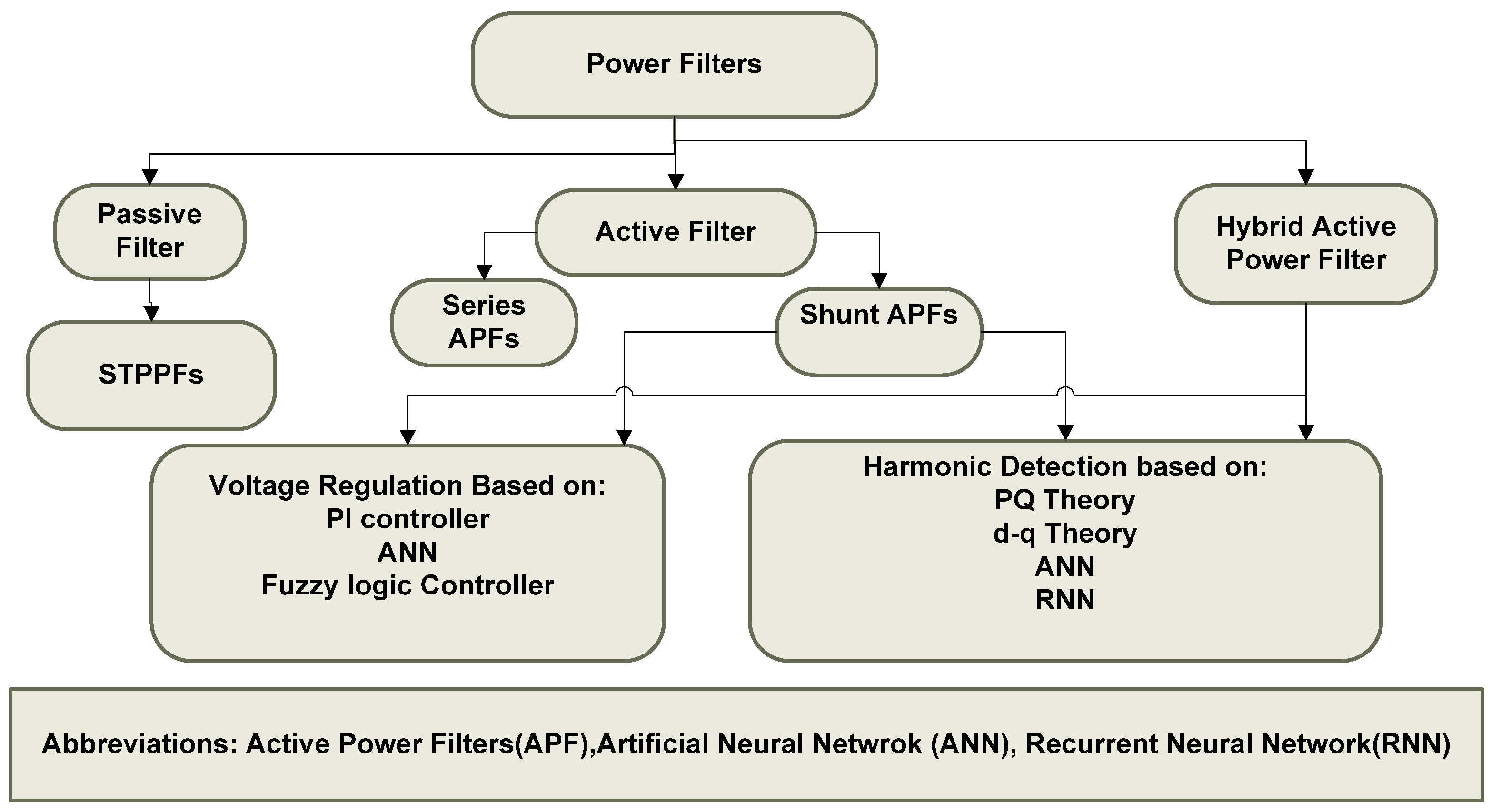
1. Introduction
- ❖
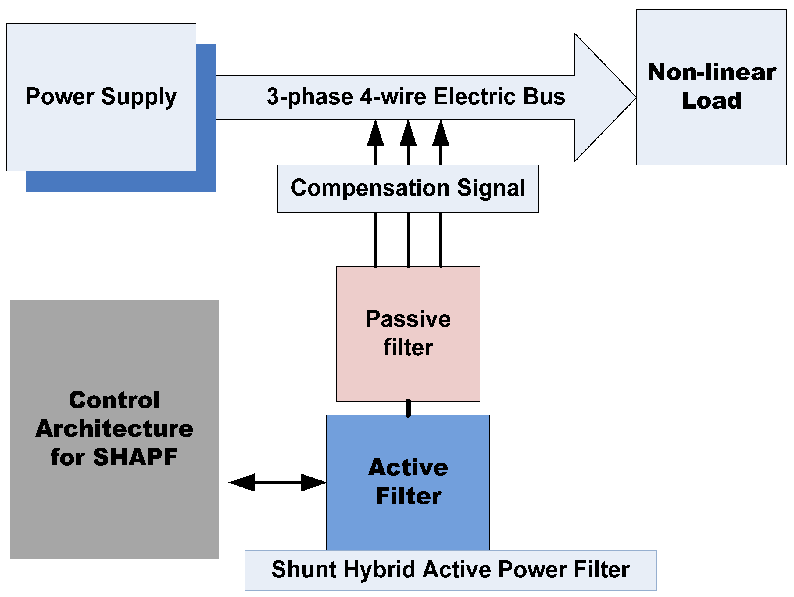
- Implementation of SHAPF topology for a four-wire three-phase system for harmonic removal and DC voltage regulation;
- ❖
- The controller implemented for the SHAPF has been optimized using machine learning algorithms such as RNN, ANN, and GRU. Deep learning algorithms outperformed the feedforward neural networks;
- ❖
- The evaluations have been performed on three different nonlinear load scenarios;
- ❖
- There is also a comparative analysis of the ANN-based controller and GRU-based approach for dealing with the time-series data.
2. Materials and Methods
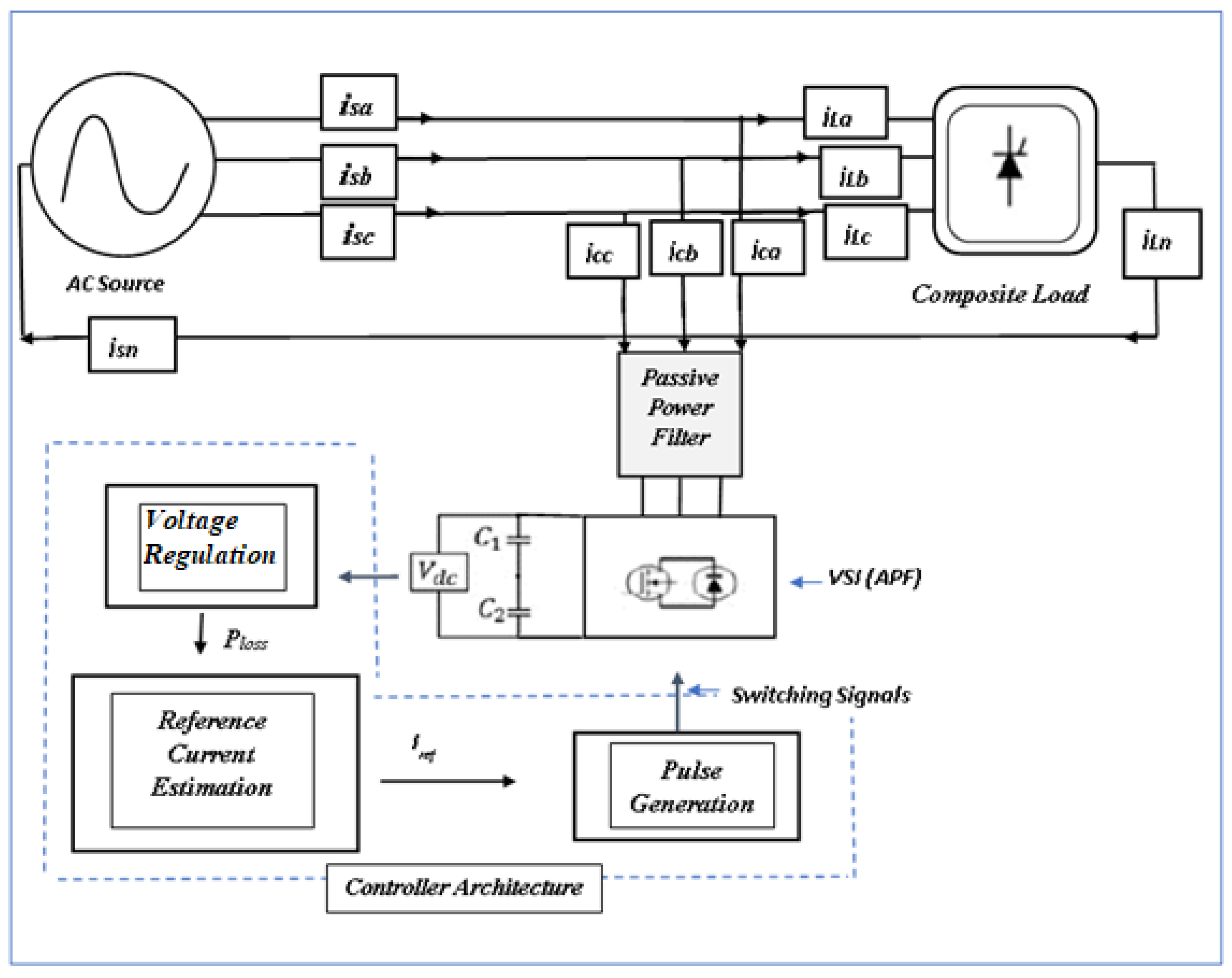
2.1. System Model
Instantaneous Power (PQ) Theory
2.2. Predictive Control Mechanisms Using Recurrent Neural Networks
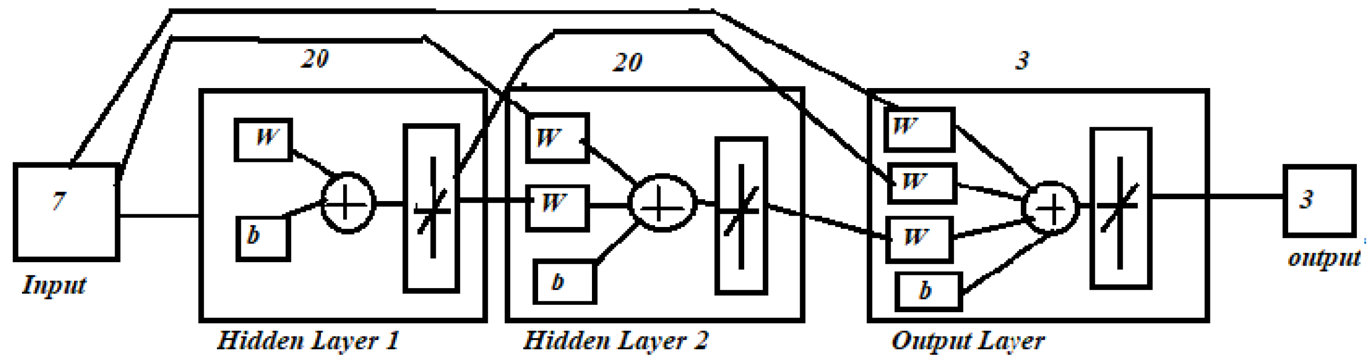
Artificial Neural Networks (ANN)
2.3. Implementation of Recurrent Neural Network
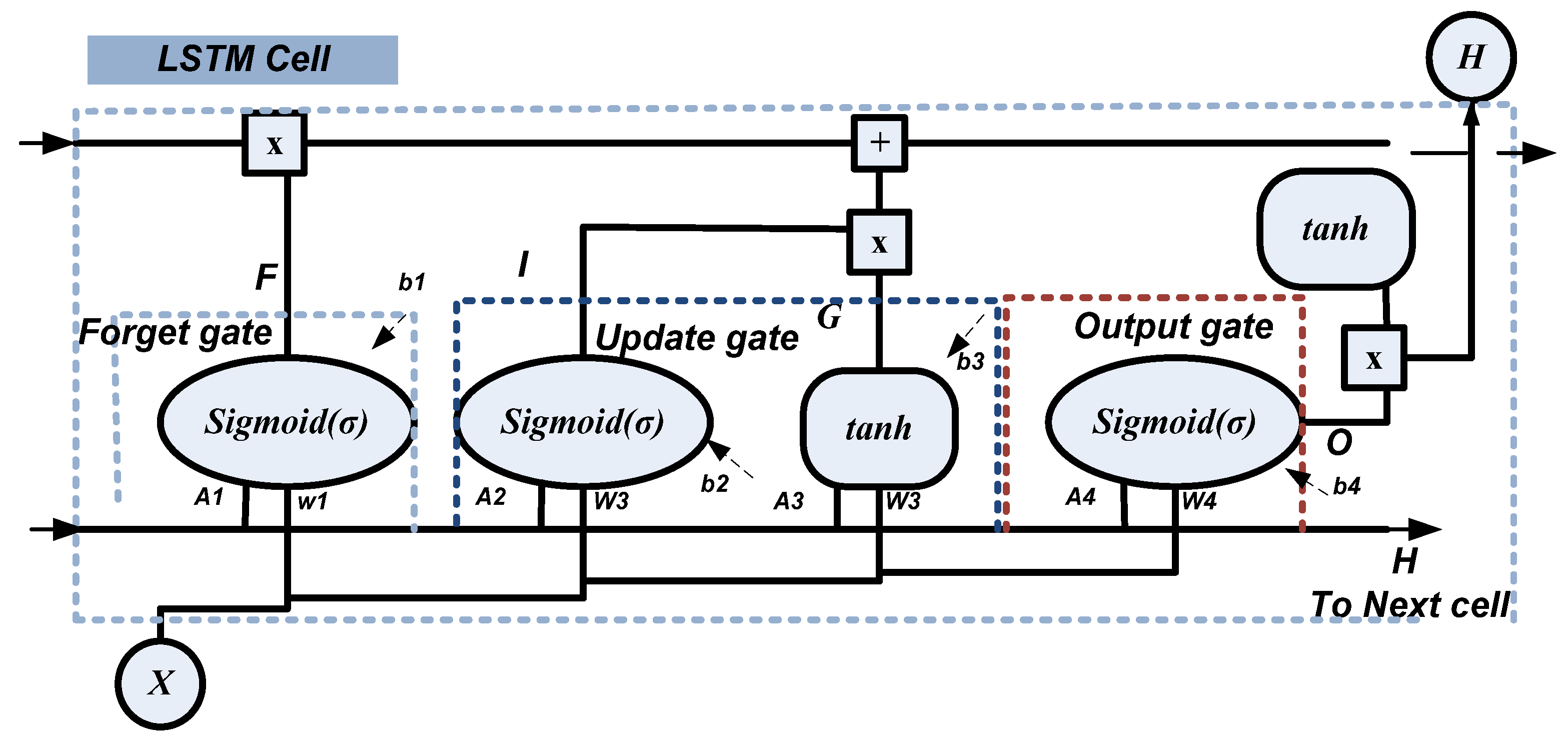
2.3.1. Long Short-Term Memory (LSTM)
LSTM Network Analysis
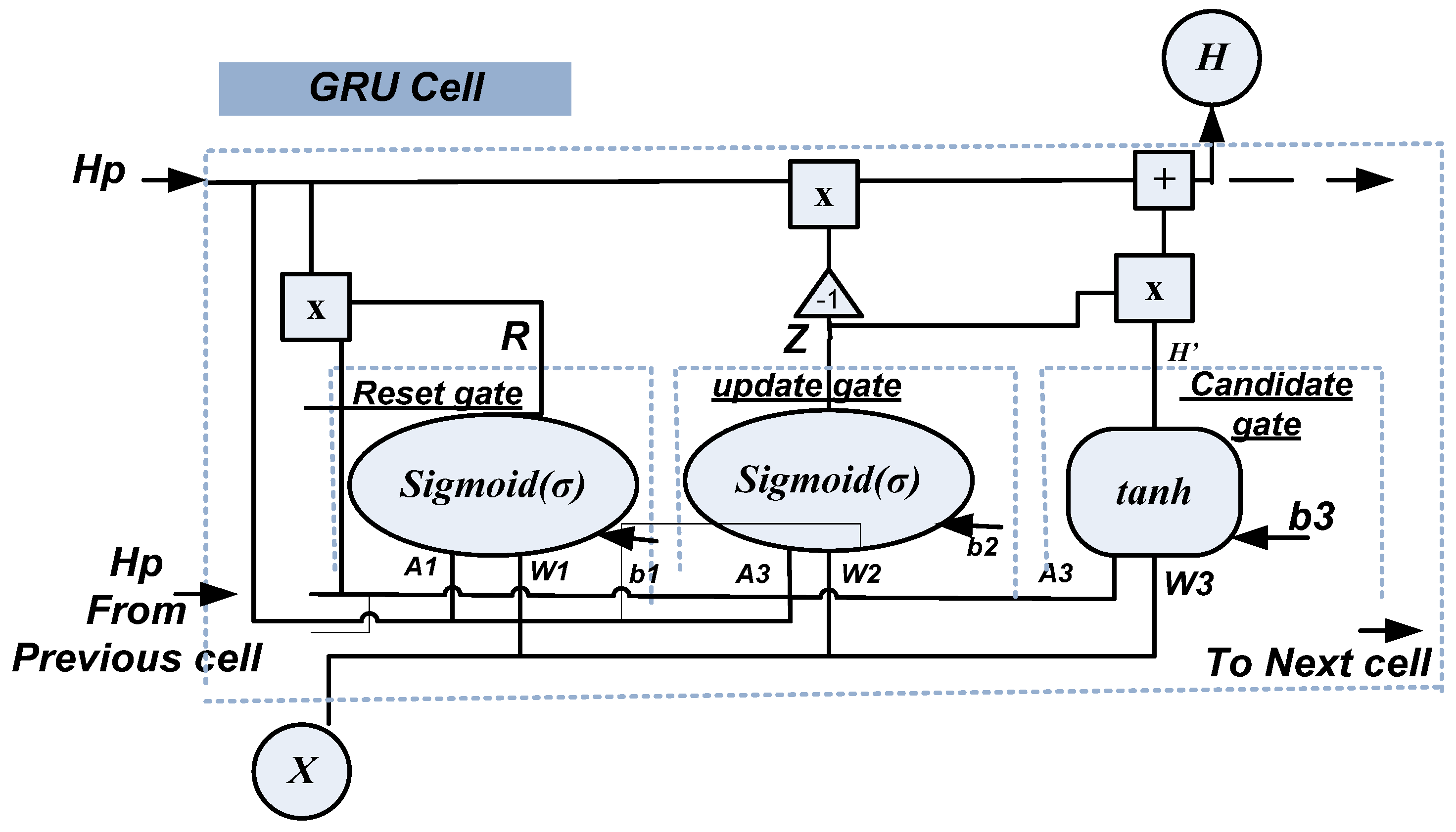
2.3.2. Gated Recurrent Unit (GRU)
GRU Network Analysis
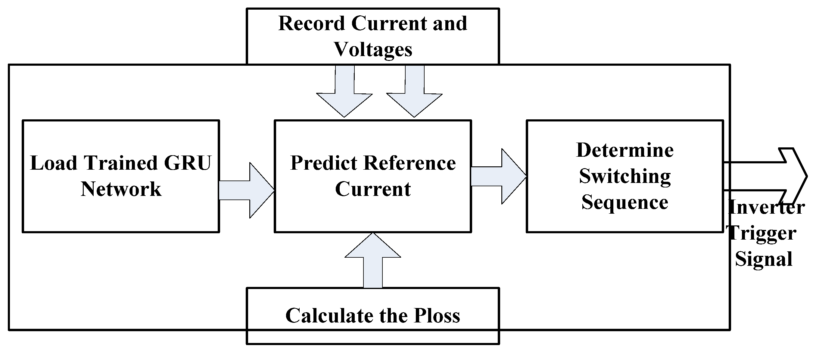
2.4. Implementation of MATLAB/Simulink Model
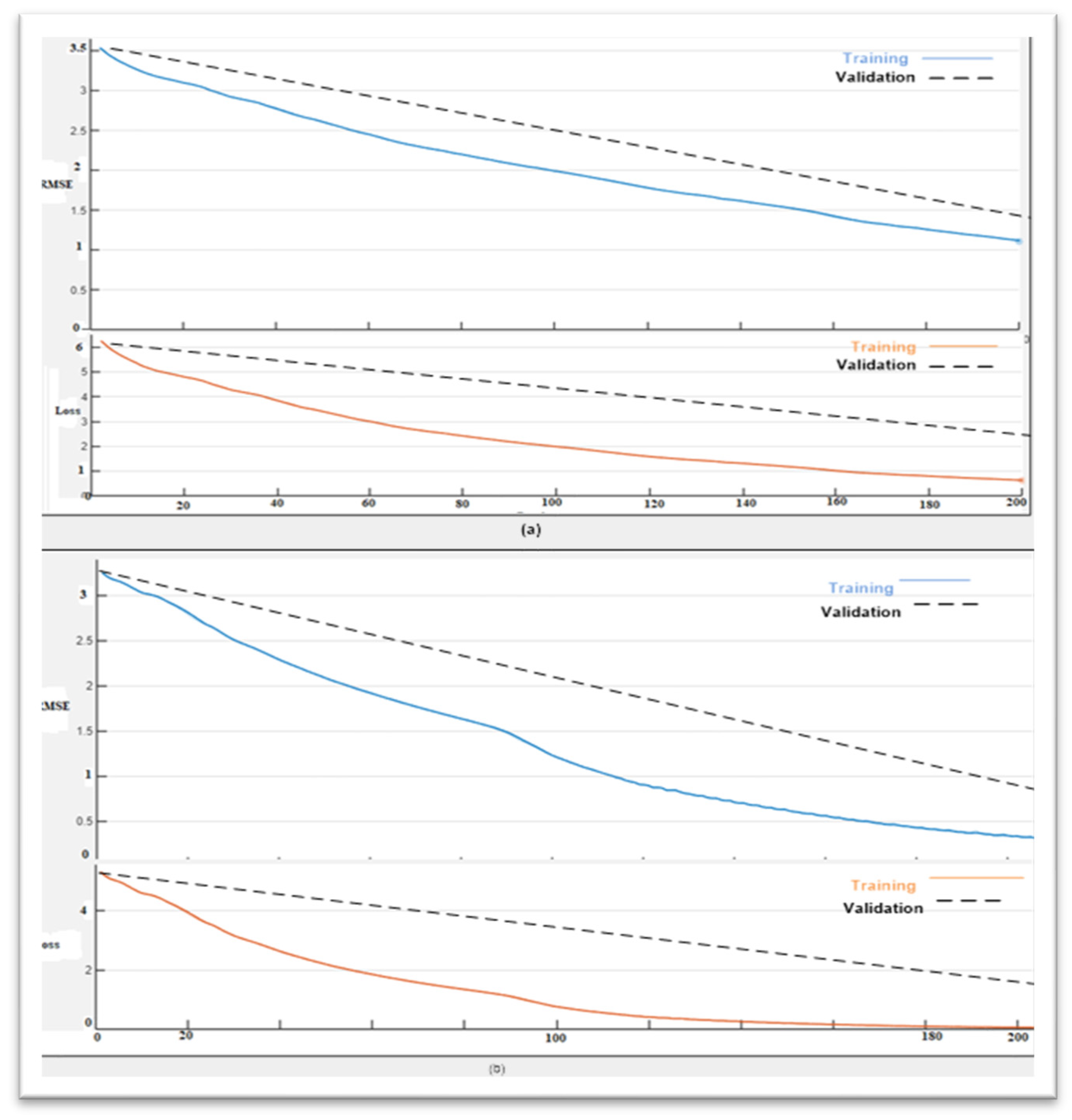
Training and Prediction
3. Results
3.1. THD Reduction Case 1
3.2. Case 2 and Case 3 Results
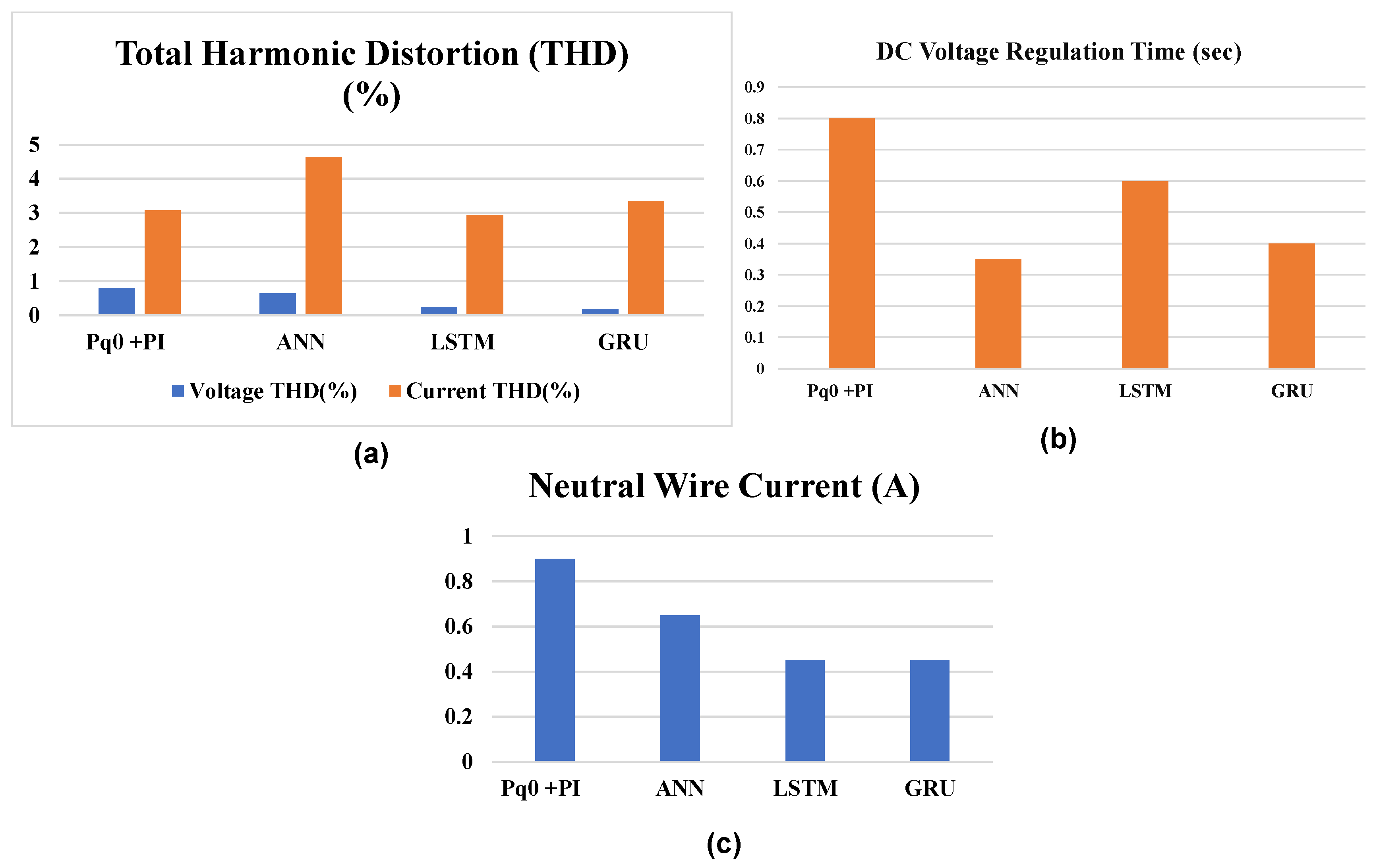
3.3. DC Voltage Regulation and Neutral Wire Current
3.4. Resonance Elimination
3.5. Algorithms Performance Comparison
4. Discussion
5. Conclusions
Author Contributions
Funding
Institutional Review Board Statement
Informed Consent Statement
Data Availability Statement
Acknowledgments
Conflicts of Interest
References
- Gunther, E. Harmonic and inter harmonic measurement according to IEEE 519 and IEC 61000-4-7. In Proceedings of the IEEE/PES Transmission and Distribution Conference and Exhibition, Dallas, TX, USA, 21–24 May 2006; pp. 223–225. [Google Scholar]
- Karbasforooshan, M.-S.; Monfared, M. Adaptive Self-Tuned Current Controller Design for an LCL-Filtered LC-Tuned Single-Phase Shunt Hybrid Active Power Filter. IEEE Trans. Power Deliv. 2022, 37, 2747–2756. [Google Scholar] [CrossRef]
- Jannesar, M.R.; Sedighi, A.; Savaghebi, M.; Anvari-Moghaddam, A.; Guerrero, J.M. Optimal probabilistic planning of passive harmonic filters in distribution networks with high penetration of photovoltaic generation. Int. J. Electr. Power Energy Syst. 2019, 110, 332–348. [Google Scholar] [CrossRef]
- Abdul Kahar, N.H.B.; Zobaa, A.F. Application of mixed integer distributed ant colony optimization to the design of undamped single-tuned passive filters based harmonics mitigation. Swarm Evol. Comput. 2019, 44, 187–199. [Google Scholar] [CrossRef]
- Yeetum, W.; Kinnares, V. Parallel active power filter based on source current detection for antiparallel resonance with robustness to parameter variations in power systems. IEEE Trans. Ind. Electron. 2019, 66, 876–886. [Google Scholar] [CrossRef]
- Omran, M.; Ibrahim, I.; Ahmad, A.; Salem, M.; Almelian, M.; Jusoh, A.; Sutikno, T. Comparisons of PI and ANN controllers for shunt HPF based on STF-PQ algorithm under distorted grid voltage. Int. J. Power Electron. Drive Syst. 2019, 10, 1339–1346. [Google Scholar] [CrossRef]
- Abdeslam, D.O.; Wira, P.; Merckle, J.; Flieller, D.; Chapuis, Y.-A. Unified artificial neural network architecture for active power filters. IEEE Trans. Ind. Electron. 2007, 54, 61–76. [Google Scholar] [CrossRef]
- Kazemi-Robati, E.; Sepasian, M.S. Passive harmonic Filter planning considering daily load variations and distribution system reconfiguration. Electr. Power Syst. Res. 2019, 166, 125–135. [Google Scholar] [CrossRef]
- Elkholy, M.M.; El-Hameed, M.A.; El-Fergany, A.A. Harmonic analysis of hybrid renewable microgrids comprising optimal design of passive filters and uncertainties. Electr. Power Syst. Res. 2018, 163, 491–501. [Google Scholar] [CrossRef]
- Fabricio, E.L.L.; Junior, S.C.S.; Jacobina, C.B.; de Rossiter Correa, M.B. Analysis of main topologies of shunt active power filters applied to four-wire systems. IEEE Trans. Power Electron. 2018, 33, 2100–2112. [Google Scholar] [CrossRef]
- Santiprapan, P.; Areerak, K.L.; Areerak, K.N. Mathematical model and control strategy on DQ frame for shunt active power filters. Int. J. Electr. Comput. Eng. 2011, 5, 1669–1677. [Google Scholar]
- Fei, J.; Wang, T. Adaptive fuzzy-neural-network based on RBFNN control for active power filter. Int. J. Mach. Learn. Cybern. 2019, 10, 1139–1150. [Google Scholar] [CrossRef]
- Zhao, Y.; Milanović, J.V. Probabilistic Harmonic Estimation in Uncertain Transmission Networks Using Sequential ANNs. In Proceedings of the 2022 20th International Conference on Harmonics & Quality of Power (ICHQP), Naples, Italy, 29 May–1 June 2022. [Google Scholar] [CrossRef]
- Fei, J.; Chu, Y. Double hidden layer output feedback neural adaptive global sliding mode control of active power filter. IEEE Trans. Power Electron. 2020, 35, 3069–3084. [Google Scholar] [CrossRef]
- Qasim, M.; Kanjiya, P.; Khadkikar, V. Artificial-neural-network-based phase-locking scheme for active power filters. IEEE Trans. Ind. Electron. 2014, 61, 3857–3866. [Google Scholar] [CrossRef]
- Hamiche, L.; Saad, S.; Merabet, L.; Zaamouche, F. Adaline neural network and real-imaginary instantaneous powers method for harmonic identification. Synth. Rev. Sci. Technol. 2018, 36, 129–140. [Google Scholar]
- Kołek, K.; Firlit, A. A New Optimal Current Controller for a Three-Phase Shunt Active Power Filter Based on Karush–Kuhn–Tucker Conditions. Energies 2021, 14, 6381. [Google Scholar] [CrossRef]
- Chilipi, R.; Al Sayari, N.; Al Hosani, K.; Fasil, M.; Beig, A.R. Third order sinusoidal integrator (TOSSI)-based control algorithm for shunt active power filter under distorted and unbalanced voltage conditions. Int. J. Electr. Power Energy Syst. 2018, 96, 152–162. [Google Scholar] [CrossRef]
- Fei, J.; Fang, Y.; Wang, T. Adaptive Fuzzy-Neural-Network Control of Active Power Filter Using Fuzzy Backstepping Approach. In Proceedings of the 2019 First International Symposium on Instrumentation, Control, Artificial Intelligence, and Robotics (ICA-SYMP), Bangkok, Thailand, 16–18 January 2019. [Google Scholar] [CrossRef]
- Elgammal, A.A.A.; El-Naggar, M.F. MOPSO-based optimal control of shunt active power filter using a variable structure fuzzy logic sliding mode controller for hybrid (FC-PV-wind-battery) energy utilization scheme. IET Renew. Power Gener. 2017, 11, 1148–1156. [Google Scholar] [CrossRef]
- Buła, D.; Grabowski, D.; Lewandowski, M.; Maciążek, M.; Piwowar, A. Software Solution for Modeling, Sizing, and Allocation of Active Power Filters in Distribution Networks. Energies 2021, 14, 133. [Google Scholar] [CrossRef]
- Dey, P.; Mekhilef, S. Current harmonics compensation three-phase has four-wire shunt hybrid active power filter based modified D–Q theory. IET Power Electron. 2015, 8, 2265–2280. [Google Scholar] [CrossRef]
- Rashmi, M.N.; Meenakshi, A.; Namratha, M.; Nayana, S.V.; Archana, K. Power quality improvement using hybrid filters. In Proceedings of the 3rd IEEE International Conference on Recent Trends in Electronics, Information & Communication Technology (RTEICT), Bangalore, India, 18–19 May 2018; pp. 804–808. [Google Scholar]
- Durna, E. Adaptive fuzzy hysteresis band current control for reducing switching losses of hybrid active power filter. IET Power Electron. 2018, 11, 937–944. [Google Scholar] [CrossRef]
- Iqbal, M.; Jawad, M.; Jaffery, M.H.; Akhtar, S.; Rafiq, M.N.; Qureshi, M.B.; Ansari, A.R.; Nawaz, R. Neural Networks Based Shunt Hybrid Active Power Filter for Harmonic Elimination. IEEE Access 2021, 9, 69913–69925. [Google Scholar] [CrossRef]
- Khan, A.; Jaffery, M.; Javed, Y.; Arshad, J.; Rehman, A.; Khan, R.; Bajaj, M.; Kaabar, M. Hardware-in-the-Loop Implementation and Performance Evaluation of Three-Phase Hybrid Shunt Active Power Filter for Power Quality Improvement. Math. Probl. Eng. 2021, 2021, 8032793. [Google Scholar] [CrossRef]
- Rizwan, R.; Arshad, J.; Almogren, A.; Jaffery, M.H.; Yousaf, A.; Khan, A.; Ur Rehman, A.; Shafiq, M. Implementation of ANN-Based Embedded Hybrid Power Filter Using HIL-Topology with Real-Time Data Visualization through Node-RED. Energies 2021, 14, 7127. [Google Scholar] [CrossRef]
- Daou, N.; Montoya, F.G.; Ababssi, N.; Djeghader, Y. A Hybrid Active Filter Using the Backstepping Controller for Harmonic Current Compensation. Symmetry 2019, 11, 1161. [Google Scholar] [CrossRef]
- Popescu, M.; Bitoleanu, A.; Linca, M.; Suru, C.V. Improving Power Quality by a Four-Wire Shunt Active Power Filter: A Case Study. Energies 2021, 14, 1951. [Google Scholar] [CrossRef]
- Mishra, A.K.; Ray, P.K.; Mallick, R.K.; Mohanty, A.; Das, S.R. Adaptive fuzzy controlled hybrid shunt active power filter for power quality enhancement. Neural Comput. Appl. 2021, 33, 1435–1452. [Google Scholar] [CrossRef]
- Kumar, M.; Uqaili, M.A.; Memon, Z.A.; Das, B. Experimental Harmonics Analysis of UPS (Uninterrupted Power Supply) System and Mitigation Using Single-Phase Half-Bridge HAPF (Hybrid Active Power Filter) Based on Novel Fuzzy Logic Current Controller (FLCC) for Reference Current Extraction (RCE). Adv. Fuzzy Syst. 2022, 2022, 5466268. [Google Scholar] [CrossRef]
- Liao, K.; Pang, B.; Yang, J.; He, Z. Compensation Strategy of Wideband Voltage Harmonics for Doubly-Fed Induction Generator. IEEE Trans. Energy Convers. 2022. [Google Scholar] [CrossRef]
- ArunKumar, K.E.; Kalaga, D.V.; Kumar, C.M.S.; Kawaji, M.; Brenza, T.M. Comparative analysis of Gated Recurrent Units (GRU), long Short-Term memory (LSTM) cells, autoregressive Integrated moving average (ARIMA), seasonal autoregressive Integrated moving average (SARIMA) for forecasting COVID-19 trends. Alex. Eng. J. 2022, 61, 7585–7603. [Google Scholar] [CrossRef]
- Gao, W.; Wai, R.-J. A Novel Fault Identification Method for Photovoltaic Array via Convolutional Neural Network and Residual Gated Recurrent Unit. IEEE Access 2020, 8, 159493–159510. [Google Scholar] [CrossRef]
- Mikkili, S.; Panda, A.K. Instantaneous active and reactive power and current strategies for current harmonics cancellation in 3-ph 4wire SHAF with both PI and fuzzy controllers. Energy Power Eng. 2011, 3, 285–298. [Google Scholar] [CrossRef]
- Sadeghi, H.; Mohammadi, H.R. An improved fuzzy controlled back-to-back electric spring using hybrid structure of ES-1 and shunt-APF to improve power quality in microgrids. Int. J. Ind. Electron. Control. Optim. 2022, 5, 89–98. [Google Scholar]
- Hamad, Z.; Abdulrahman, I. Deep learning-based load forecasting considering data reshaping using MATLAB\Simulink. Int. J. Energy Environ. Eng. 2022, 13, 853–869. [Google Scholar] [CrossRef]
- Chung, J.; Gulcehre, C.; Cho, K.H.; Bengio, Y. Empirical Evaluation of Gated Recurrent Neural Networks on Sequence Modeling. arXiv 2014, arXiv:1412.3555. [Google Scholar]
- Yunus, R.; Arif, O.; Afzal, H.; Amjad, M.F.; Abbas, H.; Bokhari, H.N.; Haider, S.T.; Zafar, N.; Nawaz, R. A framework to estimate the nutritional value of food real-time time using deep learning techniques. IEEE Access 2019, 7, 2643–2652. [Google Scholar] [CrossRef]
- Hassan, S.-U.; Imran, M.; Iqbal, S.; Aljohani, N.R.; Nawaz, R. Deep context of citations using machine-learning models in scholarly full-text articles. Scientometrics 2018, 117, 1645–1662. [Google Scholar] [CrossRef]


| System Parameters | Physical Values |
|---|---|
| Ⴔ-voltage (RMS) | 220 V |
| Frequency | 50 Hz |
| Composite Load | 3-single-phase rectifier R = 43.2 Ω L = 34.5 mH C = 292 µF (720 VAR) |
| Power Rating | 10 kVA |
| Passive Filter (5th Harmonic Tuned) | Rf = 1 mΩ Lf = 3 mH |
| DC Link for VSI | C = 470 µF Vref = 622 V |
| Name | Type | Activations | Learnables | |
|---|---|---|---|---|
| 1 | Sequence input Sequence input with 3 dimensions | Sequence input | 3 | - |
| 2 | ReLU ReLU | ReLU | 3 | |
| 3 | LSTM LSTM with 100 hidden units | LSTM | 100 | Inputweights 400 × 3 Recurrent weights Bias 400 × 1 |
| 4 | FC 1 fully connected layer | Fully connected | 1 | Weights 1 × 100 Bias 1 × 1 |
| 5 | Regression output Mean-squared error | Regression output | 1 | - |
| Name | Type | Activations | Learnables | |
|---|---|---|---|---|
| 1 | Sequence input Sequence input with 3 dimensions | Sequence input | 3 | - |
| 2 | ReLU ReLU | ReLU | 3 | |
| 3 | GRU GRU with 100 hidden units | GRU | 100 | Inputweights 300 × 3 Recurrent weights Bias 300 × 1 |
| 4 | FC 1 fully connected layer | Fully connected | 1 | Weights 1 × 100 Bias 1 × 1 |
| 5 | Regression output Mean-squared error | Regression output | 1 | - |
| Test Case | |
|---|---|
| Case 1 | Fixed RLC with 3-phase rectifier |
| Case 2 | Variable RLC with 3-phase rectifier |
| Case 3 | Fixed RLC with DC motor |
| Test Case | Technique | Voltage THD (%) | Source Current THD (%) | Load Current THD (%) | Power Factor | ||||||||
|---|---|---|---|---|---|---|---|---|---|---|---|---|---|
| Phase (a) | Phase (b) | Phase (c) | Phase (a) | Phase (b) | Phase (c) | Phase (a) | Phase (b) | Phase (c) | Phase (a) | Phase (b) | Phase (c) | ||
| Case 1 | Without Filter | 13.05 | 14.25 | 12.01 | 58.07 | 67.4 | 50.8 | 58.07 | 67.4 | 50.8 | 0.83 | 0.78 | 0.80 |
| Pq0 +PI | 0.79 | 1.02 | 0.87 | 3.08 | 5.03 | 3.79 | 58.07 | 67.4 | 50.8 | 1 | 1 | 1 | |
| ANN | 0.64 | 0.96 | 0.56 | 4.64 | 4.20 | 3.73 | 58.07 | 67.4 | 50.8 | 0.998 | 0.99 | 0.99 | |
| LSTM | 0.24 | 0.26 | 0.19 | 2.94 | 5.01 | 2.94 | 58.07 | 67.4 | 50.8 | 1 | 1 | 1 | |
| GRU | 0.18 | 0.17 | 0.18 | 3.35 | 3.34 | 3.20 | 58.07 | 67.4 | 50.8 | 1 | 1 | 1 | |
| Case 2(a) | No Filter | 9.79 | 10.25 | 8.87 | 15.27 | 17.89 | 17.59 | 15.27 | 17.89 | 17.59 | 0.96 | 0.99 | 0.99 |
| Pq0 +PI | 0.24 | 0.24 | 0.24 | 3.62 | 7.22 | 2.35 | 15.27 | 17.89 | 17.59 | 1 | 1 | 1 | |
| ANN | 0.74 | 0.90 | 0.53 | 6.29 | 5.88 | 12.98 | 15.27 | 17.89 | 17.59 | 0.99 | 0.99 | 1 | |
| LSTM | 0.21 | 0.29 | 0.11 | 1.9 | 2.1 | 2.77 | 15.27 | 17.89 | 17.59 | 1 | 1 | 1 | |
| GRU | 0.09 | 0.11 | 0.11 | 2.49 | 2.02 | 2.27 | 15.27 | 17.89 | 17.59 | 1 | 1 | 1 | |
| Case 2(b) | No Filter | 13.05 | 14.2 | 12.0 | 37.89 | 38.70 | 37.29 | 37.89 | 38.70 | 37.29 | 0.96 | 0.91 | 0.91 |
| Pq0 +PI | 0.34 | 0.44 | 0.54 | 2.49 | 3.16 | 4.0 | 37.89 | 38.70 | 37.29 | 1 | 1 | 1 | |
| ANN | 0.64 | 0.96 | 0.56 | 3.25 | 3.16 | 3.30 | 37.89 | 38.70 | 37.29 | 0.96 | 0.93 | 0.98 | |
| LSTM GRU | 0.24 | 0.29 | 0.19 | 2.05 | 2.00 | 1.90 | 37.89 | 38.70 | 37.29 | 1 | 1 | 1 | |
| 0.18 | 0.17 | 0.18 | 2.49 | 2.02 | 2.05 | 37.89 | 38.70 | 37.29 | 1 | 1 | 1 | ||
| Case 3 | No Filter | 13.1 | 14.3 | 12.3 | 57.14 | 61.17 | 48.12 | 57.14 | 61.17 | 48.12 | 0.82 | 0.78 | 0.80 |
| Pq0 +PI | 0.79 | 1.02 | 0.87 | 3.17 | 4.02 | 3.25 | 57.14 | 61.17 | 48.12 | 1 | 1 | 1 | |
| ANN | 0.64 | 0.96 | 0.56 | 3.35 | 4.69 | 3.73 | 57.14 | 61.17 | 48.12 | 1 | 1 | 1 | |
| LSTM | 0.24 | 0.26 | 0.19 | 2.70 | 3.35 | 3.01 | 57.14 | 61.17 | 48.12 | 1 | 1 | 1 | |
| GRU | 0.18 | 0.18 | 0.18 | 2.66 | 2.94 | 2.05 | 57.14 | 61.17 | 48.12 | 1 | 1 | 1 | |
| Test Case | Technique | Neutral Wire Current (A) | DC Voltage Regulation Time(s) | DC Voltage Fluctuation (V) |
|---|---|---|---|---|
| Case 1 | Without Filter | 12 | ||
| Pq0 +PI | 0.90 | 0.8 | 6 | |
| ANN | 0.65 | 0.35 | 1.79 | |
| LSTM | 0.45 | 0.6 | 1.62 | |
| GRU | 0.45 | 0.40 | 1.5 | |
| Case 2(a) | Without Filter | 12.59 | ||
| Pq0 +PI | 0.179 | 0.85 | 8.133 | |
| ANN | 1.72 | 0.55 | 9.544 | |
| LSTM | 0.170 | 0.45 | 6.133 | |
| GRU | 0.172 | 0.40 | 5.409 | |
| Case 2(b) | Without Filter | 22.19 | ||
| Pq0 +PI | 0.179 | 0.7 | 6.124 | |
| ANN | 2.22 | 0.85 | 8.476 | |
| LSTM | 0.172 | 0.6 | 4.912 | |
| GRU | 0.102 | 0.40 | 3.188 | |
| Case 3 | Without Filter | 9.785 | ||
| Pq0 +PI | 0.515 | 0.8 | 3.623 | |
| ANN | 0.434 | 0.35 | 1.709 | |
| LSTM | 0.414 | 0.6 | 2.877 | |
| GRU | 0.354 | 0.40 | 2.056 |
| Before Compensation | After Compensation | ||||||
|---|---|---|---|---|---|---|---|
| Capabilities | Topology | THDIS(%) | Isn(A) | DPF | THDIS(%) | Isn(A) | DPF |
| Parallel Resonance Prevention | PPF | 35.77 | 12 | 0.78 | 40.00 | 11.49 | 0.97 |
| SHAPF | 35.77 | 12 | 0.78 | 3.17 | 0.519 | 0.99 | |
| Series Resonance Prevention | PPF | 35.77 | 12 | 0.78 | 51.09 | 13.1 | 0.98 |
| SHAPF | 35.77 | 12 | 0.78 | 4.38 | 0.61 | 1 | |
| RNN Algorithm | Training | Prediction | Loss | RMSE |
|---|---|---|---|---|
| Long Short-Term Memory(LSTM) | Yes | Yes | 0.3 | 0.6 |
| Gated Recurrent Unit(GRU) | Yes | Yes | 0.0 | 0.2 |
Publisher’s Note: MDPI stays neutral with regard to jurisdictional claims in published maps and institutional affiliations. |
© 2022 by the authors. Licensee MDPI, Basel, Switzerland. This article is an open access article distributed under the terms and conditions of the Creative Commons Attribution (CC BY) license (https://creativecommons.org/licenses/by/4.0/).
Share and Cite
Ali, A.; Rehman, A.U.; Almogren, A.; Eldin, E.T.; Kaleem, M. Application of Deep Learning Gated Recurrent Unit in Hybrid Shunt Active Power Filter for Power Quality Enhancement. Energies 2022, 15, 7553. https://doi.org/10.3390/en15207553
Ali A, Rehman AU, Almogren A, Eldin ET, Kaleem M. Application of Deep Learning Gated Recurrent Unit in Hybrid Shunt Active Power Filter for Power Quality Enhancement. Energies. 2022; 15(20):7553. https://doi.org/10.3390/en15207553
Chicago/Turabian StyleAli, Ayesha, Ateeq Ur Rehman, Ahmad Almogren, Elsayed Tag Eldin, and Muhammad Kaleem. 2022. "Application of Deep Learning Gated Recurrent Unit in Hybrid Shunt Active Power Filter for Power Quality Enhancement" Energies 15, no. 20: 7553. https://doi.org/10.3390/en15207553
APA StyleAli, A., Rehman, A. U., Almogren, A., Eldin, E. T., & Kaleem, M. (2022). Application of Deep Learning Gated Recurrent Unit in Hybrid Shunt Active Power Filter for Power Quality Enhancement. Energies, 15(20), 7553. https://doi.org/10.3390/en15207553