1. Introduction
The potential risk of the fuel–coolant interaction (FCI, steam explosion) in severe light water reactor accidents has drawn substantial attention since the investigation of the Three Mile Island Unit 2 (TMI-2) accident reported that core melting had occurred, and a fraction of the molten core had relocated into the water-filled lower plenum. Although there was no sign of a steam explosion occurrence in TMI-2, the contact of molten fuel and coolant heightened the concern on the potential risk of an energetic steam explosion.
To estimate the magnitude of the impulse loading of steam explosion to the surrounding structures, many computer codes have been developed worldwide, such as TEXAS [
1], MC3D [
2], and TRACER-II [
3]. The computational model for steam explosion solves transient multiphase flow equations encompassing melt, coolant, water, and steam. The rate of jet breakup and the resulting particle size are computed by a constitutive relation based on either an empirical equation (jet breakup length) or a mechanistic modeling of the jet breakup process. A series of international co-works on the assessment of such FCI codes have been conducted. The outcome of the OECD/NEA SERENA project [
4], for example, indicated that melt jet breakup is one of important physics that can strongly influence the steam explosion intensity.
Liquid jet breakup is commonly encountered in many science and engineering fields, such as spray and fuel injector. The production of liquid drops from a nozzle flow, for example, has been largely investigated since the enlargement of surface area by breakup of liquid column enhances mass transfer. In general, three regimes of drop formation can be identified: (1) drop formation at the nozzle, (2) jet breakup, and (3) atomization at the nozzle [
5]. Scheele and Meister [
6] conducted a jet breakup experiment and proposed a prediction model for drop size as well as for the critical velocity below which drops are formed at the nozzle. Jet breakup in liquid–liquid systems was also studied by Skelland and Johnson [
7], and empirical correlations for drop size and jet breakup length were presented. One must note that most of the data and models proposed in these works are limited to jet diameters smaller than 10 mm.
In a severe nuclear reactor accident, the reactor vessel lower head may fail due to thermal or mechanical attack by hot molten corium inside the vessel. The size of the vessel opening through which molten corium comes out and pours into the water pool in the reactor cavity can be as large as tens of centimeter. Therefore, the jet breakup information obtained in small-diameter jets may not be applicable to large-diameter jets of fuel–coolant interaction. Capillary length scale can be used to divide small and large diameter jets. Rayleigh–Taylor instability is a phenomenon responsible for the stability of the fluid interface. When lighter fluid is accelerated toward the heavier liquid, the interface can be unstable if the wavelength of the interface is greater than the so-called critical wavelength given by Equation (1) [
8]. Using the material property given in
Table 1, an estimate of the critical wavelength for corium is ~20 mm. Therefore, experimental data as well as modeling of the jet breakup is needed for an application to reactor accident analysis of a jet diameter greater than 20 mm.
An empirical formulation of jet breakup in FCIs was first proposed by Saito et al. [
9]. A correlation of jet breakup length was proposed based on the experimental data of lighter fluid jet entering a heavier fluid pool. A jet breakup experiment using Woods metal was conducted by Kondo et al. [
10] and by Manickam et al. [
11]. Manickam et al. used Woods metal melt at low temperature to avoid boiling and obtained high-resolution visualization data to compare with their CFD simulation. Jet breakup experiments using simulant materials were also conducted by Bang et al. [
12,
13], Matsuo et al. [
14], Jung et al. [
15], and Cheng et al. [
16]. There were also analytical model developments based on the jet breakup mechanisms, such as Kelvin–Helmholtz instability (KHI) at the melt–coolant interface with relative velocity: Epstein and Fauske [
17,
18] and Bang et al. [
3]. Corradini et al. [
19] proposed a conceptual model for boundary layer stripping (BLS) rate based on the relation between boundary layer thickness and skin friction at the leading front of a spherical ball. Peng et al. [
20] recently reported a mathematical model of boundary layer stripping leading to fine fragmentation of melt drops in the phase of explosion propagation, but the formulation was too complex to be solved analytically. Instead, they proposed empirical correlations for the boundary layer stripping rate and fragmented drop size.
Both the empirical nature of jet breakup length correlations and the conceptual nature of KHI modeling are lacking in providing realistic particle size distribution from jet breakup. To overcome this shortcoming, computational fluid dynamics simulations of jet breakup have been reported recently. Thakre et al. [
21] conducted two-dimensional simulations of jet breakup using the VOF model of ANSYS Fluent. Zhou et al. [
22] conducted three-dimensional simulations of jet breakup, including the cooling and solidification modeling. Both of these CFD analyses were successful in producing the general figure of jet breakup but were not sufficient enough to provide a realistic process of jet breakup, i.e., the apparent role of boundary layer stripping and the interfacial instability. Due to the complex physics of interfacial instability and deformation, the Lattice Boltzmann modeling can be preferred sometimes, similar to the work performed by Saito et al. [
23] to the continuum mechanics of CFD-like simulations.
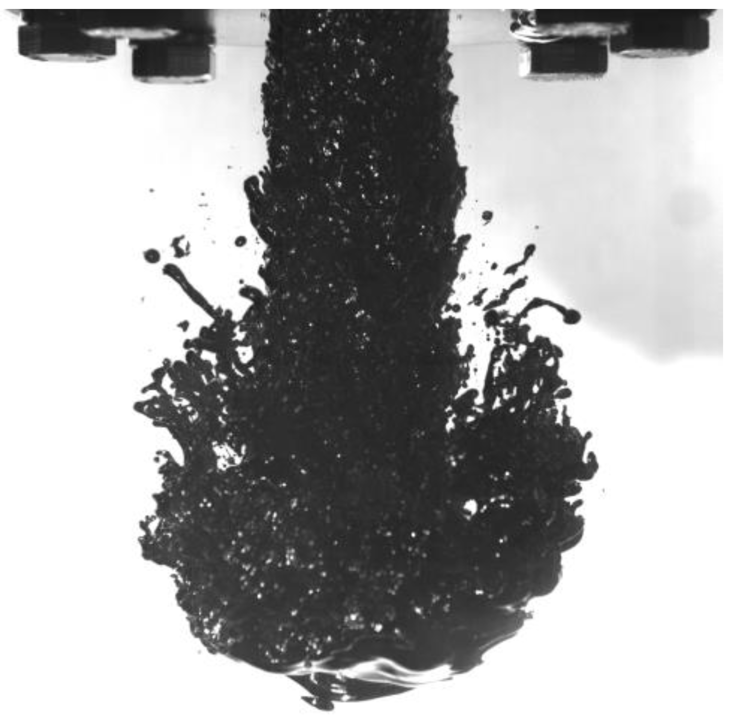
An experimental observation of Woods metal jet falling in water without boiling is shown in
Figure 1. The image of jet leading edge clearly shows the boundary layer stripping of jet breakup, and the jet lateral surface looks wavy as the unstable interface grows. One notes that the BLS is a purely hydrodynamic process so that a good multiphase CFD tool can simulate the BLS well. However, the KHI is a nature of interfacial instability, and the range of interesting wavelength could be as small as 0.1 mm. Thus, a computational simulation of KHI may require very fine meshes. The fastest growing wavelength of KHI at liquid–liquid interface can be written as Equation (2) from the linear analysis of the instability [
17]. For corium jet whose material properties are given in
Table 1, the fastest growing wavelength of KHI is 6.1 mm for 1 m/s relative velocity, but it is 0.38 mm for 4 m/s relative velocity.
To construct a computational model of melt jet breakup for the analysis of vapor explosions in severe nuclear reactor accidents, each principal mechanism of jet breakup, such as Kelvin–Helmholtz instability and boundary layer stripping, must be separately modeled. The past experimental and theoretical studies on jet breakup, however, only provide conceptual pictures and debris size information from post-test analysis from which the contribution of each mechanism cannot be distinguished. To overcome such shortcomings, the present study aims to develop a computational method of simulating liquid–liquid jet breakup from which the role of each principal mechanism can be identified, in particular, the size of drops produced in jet breakup.
Table 1.
Physical property of corium and Woods metal [
13].
Table 1.
Physical property of corium and Woods metal [
13].
| Property | Corium [4] | Woods Metal [12] |
|---|
| Composition | UO2 80% + ZrO2 20% | Bi 50% + Pb 27% + Sn 13% + Cd 10% |
| Melting temperature, °C | 2609 | 72 |
| Density, kg/m3 | 7300 | 9383 |
| Specific heat, J/kgK | 510 | 168 |
| Thermal conductivity, W/mK | 3.0 | 18.8 |
| Dynamic viscosity, Pa/s | 0.005 | 0.002 |
| Surface tension, N/m | 0.573 | 0.43 |
| Latent heat of fusion, J/kg | 280,000 | 33,500 |
2. Mathematical Model
The simulation of melt jet falling in liquid water requires a multiphase model. A treatment of melt as discrete particles could be a plausible approach, but the physics of breakup mechanism can be difficult to model. In this study, the multiphase model for melt and liquid water was volume of fluid (VOF) to track the interface during the jet breakup process. One notes that the VOF model in this study requires meshes fine enough to resolve the wavelength of interfacial waves as well as small melt drop size.
The VOF model is good for surface tracking in fixed Eulerian mesh. The volume fraction of each phase,
αp and
αq, represents the position and the interface in computational cells. If
αq = 0, phase
p only exists in the cell and phase
q only exists where
αq = 1. Naturally, the interface locates in the cell where 0 <
αq < 1. The sum of volume fractions of all phases is unity,
For the numerical method, the primary and secondary phases must be designated, and in this study, the coolant liquid was defined as the primary phase to improve solution stability. The continuity equation for phase
q can be written as the following form [
24]
where
is the mass transfer from phase
p to phase
q. For the calculation of Woods metal jet in water, there is no phase change.
The momentum equation can be written as [
24].
The continuum surface force (CSF) model proposed by Brackbill et al. [
25] was employed for surface tension force, and it is added to the momentum equation as a source term. The general form of surface tension force is
Here, ρ is volume-averaged density. It is noted that the surface tension source term for a cell is proportional to average density in the cell, as shown in Equation (6).
The energy equation is as follows [
24].
In the VOF model, phase
p and phase
q co-exist in the interface cell so that energy,
E, and temperature,
T, must be presented as mass-averaged. For example,
where
for each phase is based on the specific heat of that phase and the common temperature.
Density (
) and viscosity (
) are calculated by volume fraction averaged as Equations (9) and (10). Radiation heat transfer as well as any other volumetric energy source is included as source term,
.
For the interfacial interaction problem, such as boundary layer stripping, the Reynolds number is defined based on the distance from the leading edge, which is approximately the diameter of the jet. For water, the condition of 4 m/s jet speed and 0.05 m jet diameter gives about 2 × 10⁵ of the Reynolds number. Therefore, the flow was assumed laminar.
The geometric reconstruction scheme was used for interfacial tracking, which constructs the interface between fluids using a piecewise-linear approach. The assumption of the model is that the interface has a linear slope within each cell and uses this linear shape for the calculation of advection of the fluid through cell faces.
Material properties of Woods metal are given in
Table 1 together with prototypic corium properties for comparison. The corium and Woods metal have similar density ratios to liquid water and influence the dimensionless numbers to jet breakup; for example, the Froude number (
) and the Weber number (
) are in close ranges. This implies that Woods metal could be a good simulant to corium melt. However, when Woods metal is used for a non-boiling condition, which is often preferred to investigate the hydrodynamic nature of jet breakup with the help of clear visualization, the role of vapor film between melt and liquid coolant in the jet breakup process is ignored.
3. Results and Discussions
The present study is aimed at investigating the ability of the CFD modeling of liquid–liquid jet breakup to resolve the principal mechanisms relevant to jet breakup as well as the submillimeter-scale drop size. To make the use of the VOF model to compute jet breakup plausible, the mesh must be fine enough to track the small drops produced from the jet breakup. Experimental observations showed that the drop sizes ranged as small as submillimeter in FARO tests [
26] in which prototypic corium melt was used. This range of drop size was also observed in non-boiling Woods metal jet experiment COLDJET [
13]. Besides the drop size scale, the wavelength of unstable melt surface must also be considered in determining the required mesh size. The estimate of the fastest growing wavelength by Equation (2) indicates that the wavelength of KHI can be as small as 0.2 mm; thus, the mesh size must be smaller than 0.05 mm, i.e., one quarter of the wavelength, to resolve such a small wave. Simulation of the whole experimental domain, for example, 1 m height and 0.3 m radius of COLDJET, requires more than 100 million elements even for a two-dimensional axisymmetric calculation. The need of extensive computer resources of CPU time and memory seems to make a lab-scale computation impractical.
Therefore, the first attempt was a two-dimensional simulation of the whole domain with 0.2 mm mesh size to obtain the global behavior of the jet breakup. Then, the two-dimensional simulation of reduced domain with the much finer mesh of 0.02 mm was used to investigate the Kelvin–Helmholtz instability. Finally, a three-dimensional simulation was performed for the purpose of investigating boundary layer stripping [
27]. The COLDJET experiment was chosen for the simulation where molten Woods metal jet of 50 mm in diameter was poured into 1 m deep water pool under a non-boiling thermal condition. The initial temperatures of the jet and water were 85 °C and 40 °C, respectively. It is noted that the water temperature of COLDJET was chosen from a scaling analysis to provide a similar thermal condition to the real reactor condition in terms of melt solidification.
The time step for this transient analysis was set in general based on the condition that the Courant number () is smaller than 1. For the mesh size of 0.02 mm in KHI simulations, the time step of 1 × 10⁻⁶ s fulfilled the Courant number requirement, and the time step of 1 × 10⁻⁵ s was good for the mesh size of 0.2 mm in BLS simulations.
The numerical methods set for this VOF multiphase simulation of interfacial motion in Fluent were as follow. The pressure–velocity coupling was SIMPLE, and the discretization methods were least square cell based for gradient, PRESTO! for pressure, second order upwind for momentum, and Geo-Reconstruct for volume fraction. The transient formulation was first-order implicit. The convergence criteria for residuals were 10−3. Most of the boundaries, except the no-slip walls, are shear-free walls because the simulation domain is a part of fluid volume.
3.1. Two-Dimensional Simulation of COLDJET Experiment
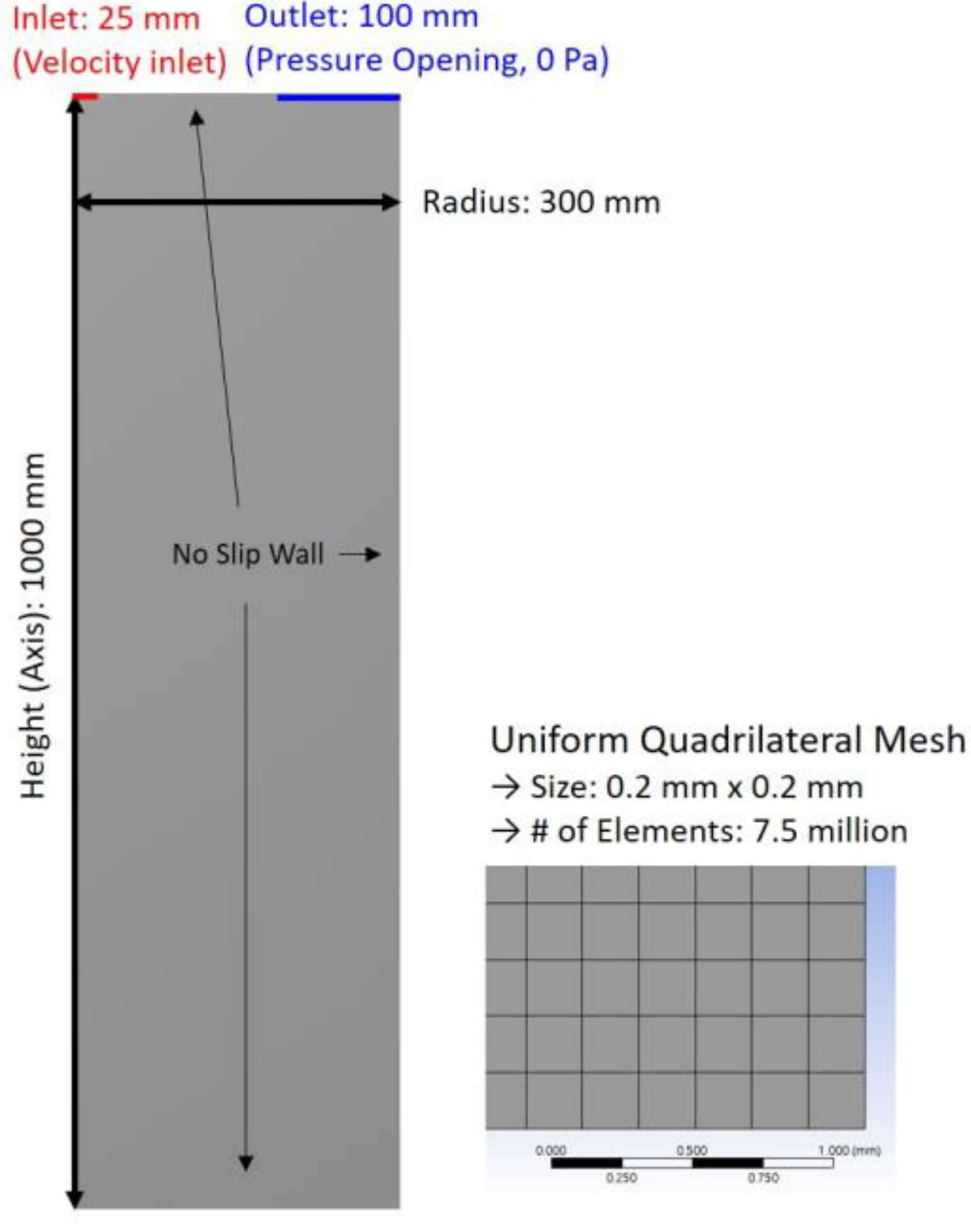
The two-dimensional simulation of the COLDJET experiment was carried out with the uniform mesh of 0.2 mm. The purpose of this simulation was to obtain a global aspect of jet breakup even though the mesh size was not small enough to resolve fine waves of KHI. The computational domain was axisymmetric with 1.0 m in height and 0.3 m in radius. The Woods metal melt jet enters the water-filled pool at the center through an inflow opening of 0.025 m in radius. The domain and mesh information are shown in
Figure 2.
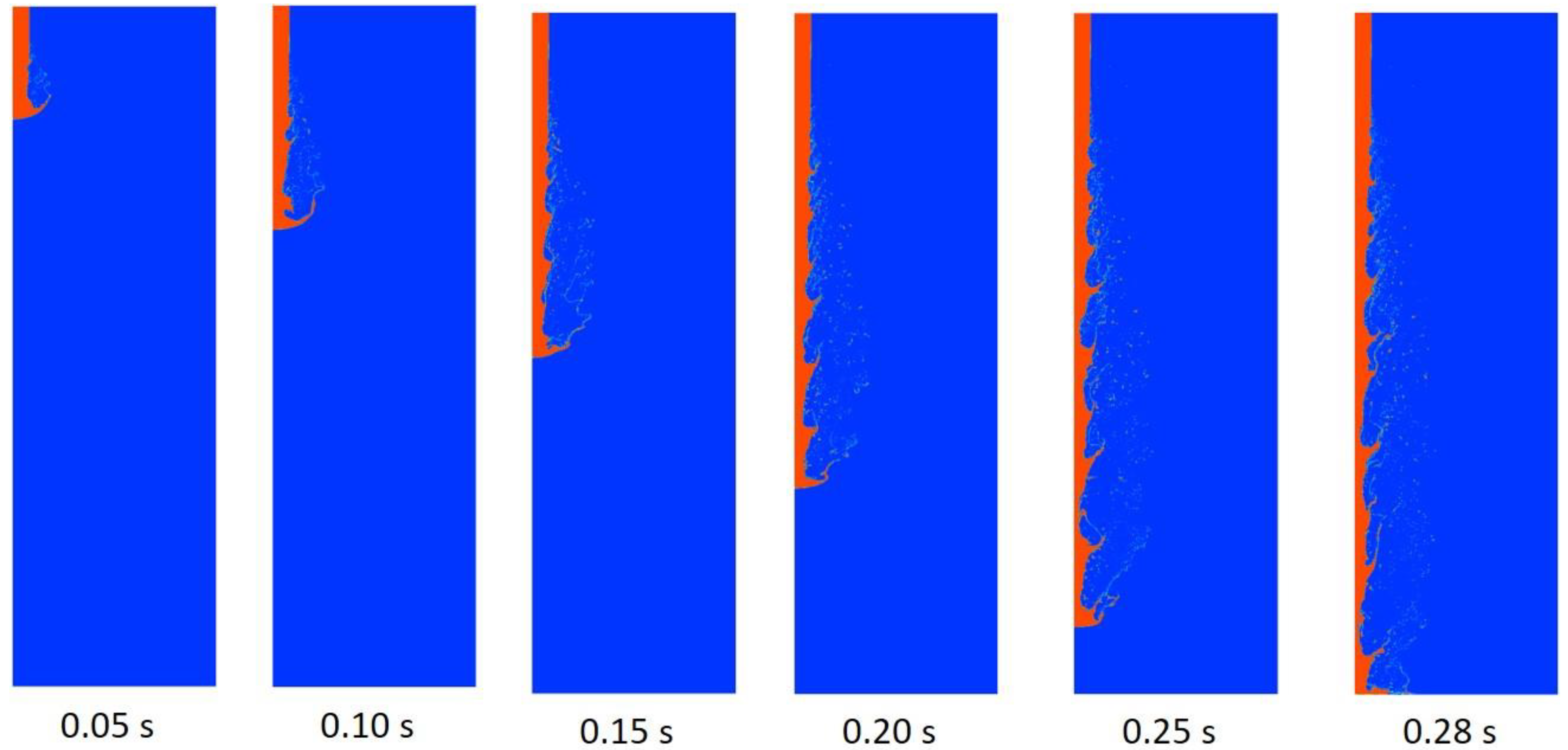
The progression of the jet breakup as melt falls through the water pool is shown in
Figure 3 for selected times. It is seen that the leading edge of the jet breaks up by the so-called boundary layer stripping, and the lateral surface of the jet undergoes Kelvin–Helmholtz instability due to the relative velocity between the jet and the surrounding liquid, as illustrated in
Figure 4. The further growth of the KHI waves results in drop formation.
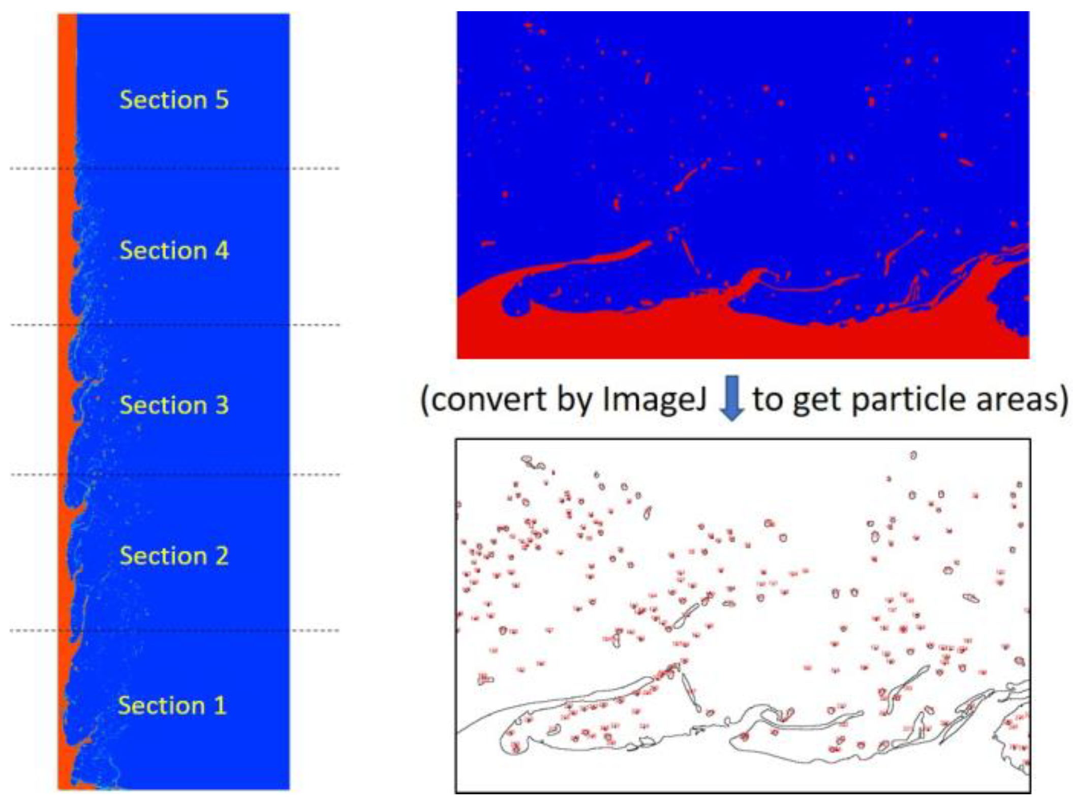
To obtain the size distribution of particles produced in the jet breakup, image analysis software (ImageJ) was used to obtain the area of each particle, and then, the equivalent diameter was calculated from it, as shown in
Figure 5. The results of the particle size distribution are shown in
Figure 6. The size distribution by number of particles shows that 60–70% of particles belong to the sizes between 0–1.0 mm in all five sections. However, the size distribution by mass of particles under the assumption of spherical shape shows that the particle size is nearly equal over the range of 0.5 to 7.0 mm.
3.2. Two-Dimensional Simulation of Kelvin–Helmholtz Instability
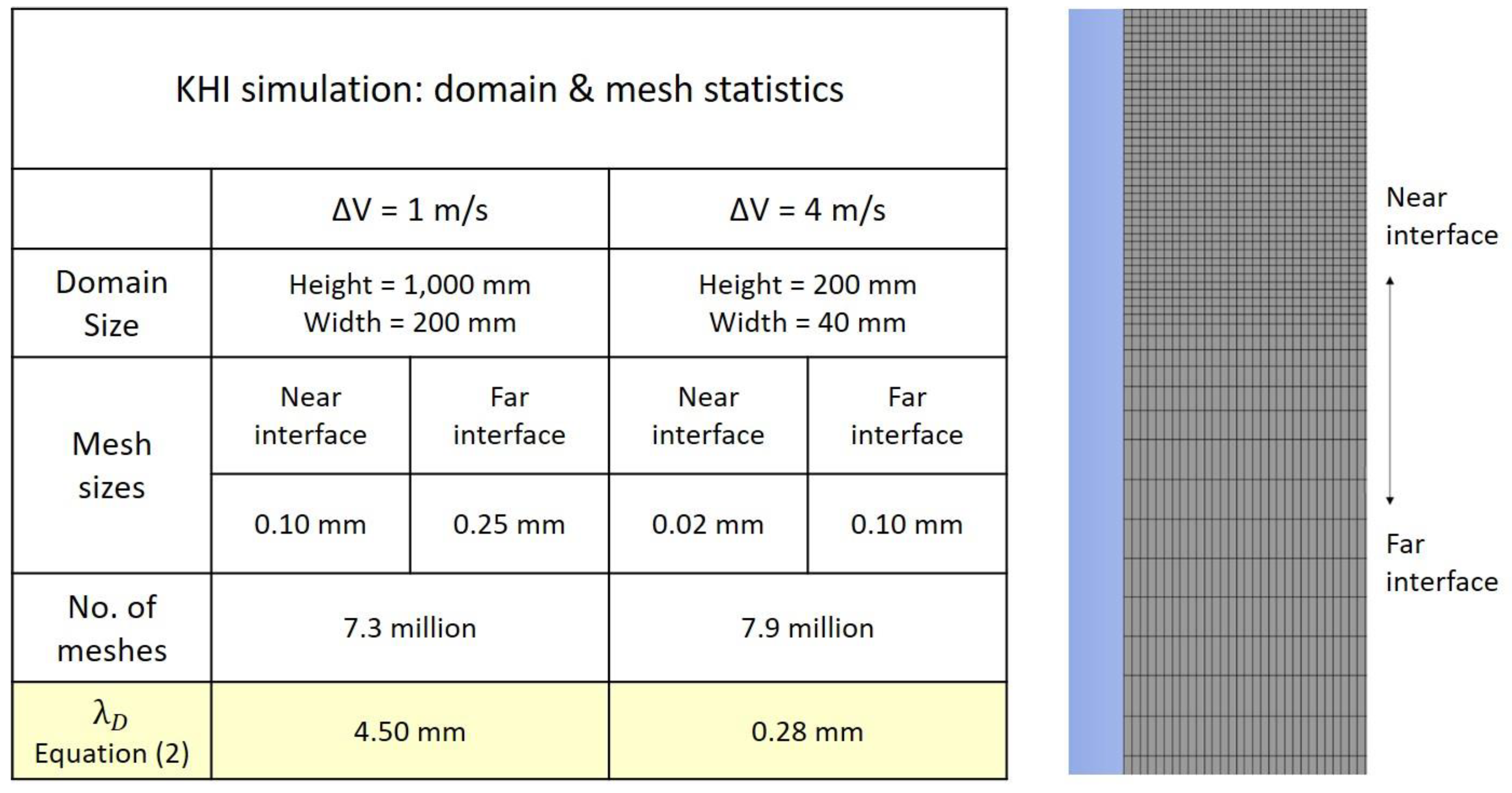
The two-dimensional simulation of the jet breakup presented above used the mesh size of 0.2 mm, which is considered a large mesh in comparison to the fastest growing wavelength of the Kelvin–Helmholtz instability. Therefore, to specifically investigate the KHI waves and their growth on the lateral surface of the jet, two-dimensional calculations with much smaller meshes were carried out. As shown in
Figure 7, the 2D domain size and mesh size varied according to the relative velocity, which was 1.0–4.0 m/s in these calculations. For the case of 4.0 m/s relative velocity, mesh size was 0.02 mm in the domain of 0.2 m in length and 0.04 m in width, which is considered large enough to contain complete growth of KHI waves.
The simulation result of the KHI wave growth is illustrated in
Figure 8. The quantification of the fastest growing wavelength of KHI is difficult when the wave amplitude is so small or irregular in magnitude. In particular, the wavelength in early growth of KHI is of importance since this CFD result and Equation (2) from linear analysis [
17] shall be compared. To systematically analyze the dominant wavelengths at the earlier time when the wave height was too small to identify, the volume fraction in the proximity of the interface was transformed into wave numbers per unit length using the fast Fourier transform (FFT) technique. As shown in
Figure 9, the FFT frequency output corresponds to the number of waves per meter; thus, the reciprocal of this is the wavelength. The calculated fastest growing wavelength is shown in
Figure 8, and it increases as the wave grows.
As seen in
Figure 9, the FFT result does not show a unique frequency, but at least the dominant frequency of the peak magnitude can be identified. The wavelength obtained by the FFT technique was compared with the graphical measurement using the contour plot of melt volume fraction and the agreement was acceptable. The value of
λD at the earliest time when it can be identified was 0.45 mm for relative velocity of 4.0 m/s and 5.64 mm for 1.0 m/s. The linear analysis of KHI (Equation (2)) gives 0.28 mm for relative velocity of 4.0 m/s and 4.8 mm for 1.0 m/s. Comparison of these numbers implies that
λD at the beginning of wave growth obtained by CFD simulation is close to the estimate by Equation (2). However, as the wave grows further,
λD increases gradually.
The particle size information was obtained by the same way as shown in
Figure 5. The interface shape and particles at the full growth of waves is illustrated in
Figure 10. The size distributions at selected times are shown in
Figure 11. At the early time, the particle size is mostly 0.3 mm, but the distribution is widened as wave growth proceeds, but the Sauter-mean diameter was less than 1.0 mm at all times of calculation.
The computational results of KHI show that the theoretical fastest growing wavelength can be seen at the very early time of wave growth, and then the wave becomes bigger gradually. This implies that the estimation of KHI particle size by the theoretical fastest growing wavelength (Equation (2)) may not be valid.
3.3. Three-Dimensional Simulation of Boundary Layer Stripping
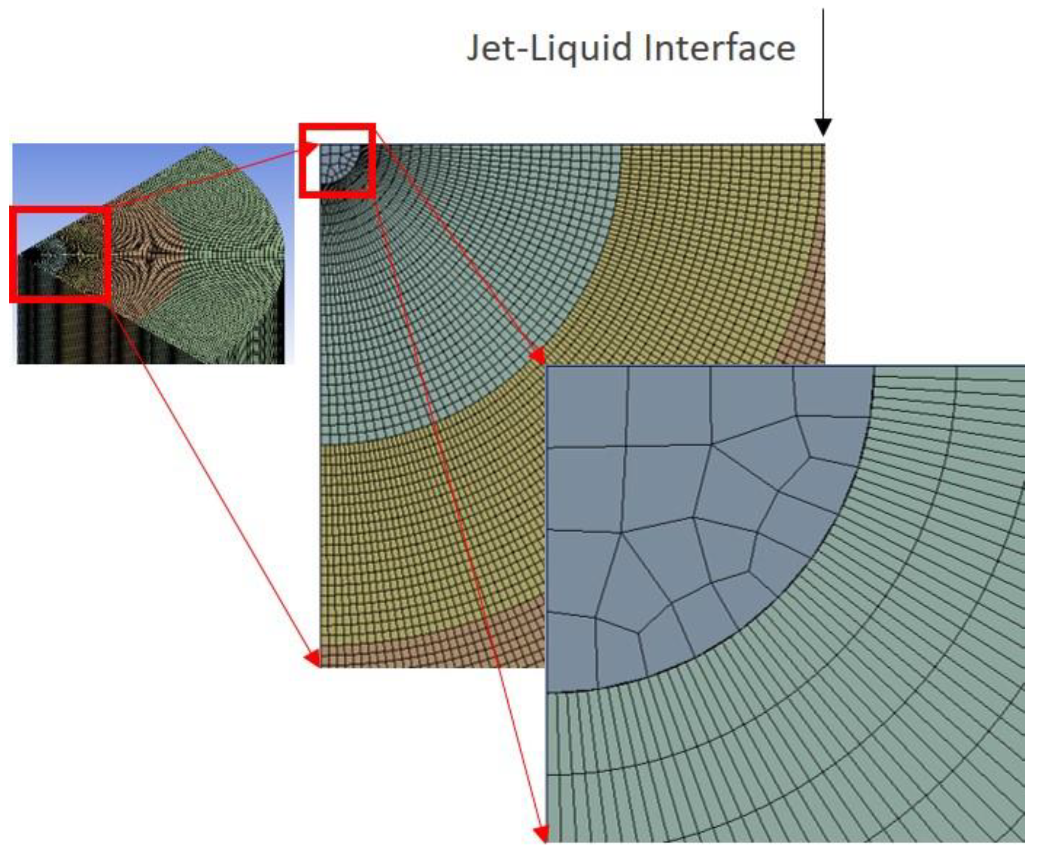
The purpose of the present simulation is to investigate boundary layer stripping of jet breakup at the leading edge in three dimension. The computational domain was a part of the water pool of the COLDJET experiment to reduce the number of meshes and computational time but was chosen to be large enough to capture the BLS process. It was one quarter of the water pool in the azimuth direction (90°) with a 240 mm pool depth and an 80 mm pool radius. The mesh size was 0.25 mm in both radial and vertical directions and 0.2–0.35 mm in the azimuth direction. The total number of cells was 36.7 million. The mesh structure is shown in
Figure 12.
The simulation results of the jet penetration into the water pool and the boundary layer stripping are shown in
Figure 13. These images were produced by iso-surface function with the melt volume fraction set at 0.5. Since solidification was not modeled, the melt drops may coalesce when the population becomes large. The velocity field near the jet leading edge is illustrated in
Figure 14. It is noted that there is only one velocity field in the VOF model. Thus, melt volume fraction contour is overlapped with the velocity field to outline the interface of melt and water, as shown by the dark solid line. Based on this velocity contour, the velocity boundary layer seems thick near the jet leading edge and a layer of lateral motion of the jet leads to eventual breakup into drops.
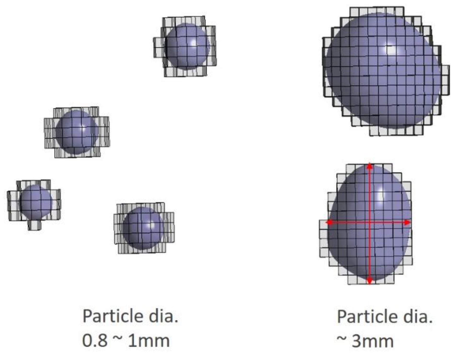
The information on the particle size produced in the jet breakup was hard to obtain directly from the Fluent post-processing, and the interfacial area was not available. Thus, a sizable number of sample particles were viewed by the iso-surface of melt volume fraction, and the particle sizes were measured by counting the number of meshes that a particle occupied. An enlarged view of the melt particle is shown in
Figure 15. The particle size distribution is shown in
Figure 16. The horizontal bars in the figures indicate the bin width of particle size counting. The total number of particles was significantly larger for the 4 m/s jet speed than for the 1 m/s jet speed. The number count distribution shows that the most probable particle size is in the bin of 0.5–1.0 mm. However, particle size distribution by mass fraction in
Figure 16 indicates that the most probable size is in the bin of 3.0–3.5 mm for the 4.0 m/s jet speed. The reason to draw particle size distribution by mass fraction is to compare the simulation result with the available experimental data that usually provide the distribution by mass fraction.
The mesh size of the base case simulation was 0.25 mm, which was considered small enough to track the interface of the smallest drop produced in the jet breakup based on experimental observations. To examine the effect of mesh size on drop size distribution, the simulation was repeated with the mesh reduced by half, 0.125 mm. For the finer mesh case, the number of meshes would be unpractically too large if the domain was kept the same as one quarter of the cylindrical pool; thus, the domain size was reduced to 1/12 of the cylinder or 30° in azimuthal angle. The behaviors of the boundary layer stripping with different mesh sizes appear similar to each other both qualitatively and quantitatively. In the finer mesh simulation, the weight % of particle size between 2.5 and 3.0 mm was unchanged at 26%, and the weight % between 2.0 and 2.5 mm slightly increased from 23% to 28%. The drop size distribution changed by an insignificant level; hence, it is concluded that the mesh size chosen for the present simulation seems adequate.
The particle size distribution of the COLDJET experiment is shown in
Figure 17. A direct comparison of particle size distribution between these simulations and the experimental data is of no significance since the experimental data contains drops produced by both Kelvin–Helmholtz instability and boundary layer stripping, while the simulations were carried out separately for KHI and BLS due to required mesh size limitation. Although a direct comparison of particle size distribution is not possible, the breakup modes can be identified in terms of particle size. For the case of initial jet speed of 4.0 m/s, the most probable size in KHI particles is smaller than 1.0 mm (
Figure 11), and the most probable size of BLS particles is 3.0–3.5 mm (
Figure 16). Thus, it is concluded that in the COLDJET experiment, the drops near or smaller than 1.0 mm were produced by Kelvin–Helmholtz instability mode, and relatively larger drops of ~3.0 mm were produced by boundary layer stripping, as outlined in
Figure 17.
The computational time could be a concern in such a fine mesh simulation. The computer used in this study has two Intel Xeon E5 CPUs with 20 cores each for a total 40 cores for parallel computing. For the case of finer mesh calculation of BLS, the computational time was about 120 h. It is noted that the domain with 50 million cells only covers 30° part of 80 mm radius and 240 mm length cylindrical jet, which is a relatively very small domain compared to an industrial system application. Therefore, such a computational effort is recommended for a phenomenological study but not for industrial applications. For industrial applications, coarse mesh computation is recommended with constitutive correlations for jet breakup processes.
4. Conclusions
The present study is aimed at developing a computational method of simulating liquid–liquid jet breakup by which the role of each principal mechanism of jet breakup can be identified, in particular, the size of drops produced in jet breakup. It is generally known that jet leading edge breaks up by boundary layer stripping (BLS), and jet lateral surface breaks up by Kelvin–Helmholtz instability (KHI). The jet breakup rate as well as the resulting particle size are important parameters that would largely govern the intensity of vapor explosion in severe nuclear reactor accidents.
First, the two-dimensional simulation of KHI along the melt–liquid coolant interface was performed using the VOF model in ANSYS Fluent with fine meshes as small as 0.02 mm. The dominant wavelength obtained by FFT analysis of calculated melt volume fractions showed that the fastest growing wavelength from the linear analysis of KHI is seen only at the very early development of the instability, and it increases gradually. This implies that the estimation of KHI particle size by the theoretical fastest growing wavelength may not be valid. Second, the three-dimensional simulation of BLS was also performed, and the shape and size of the generated melt particles were obtained. The particle size distributions from the KHI and BLS simulations were compared with the COLDJET experimental data of Woods metal and water, and it showed that the finer drops of one millimeter or smaller are produced by Kelvin–Helmholtz instability, and the drops of a few millimeters in diameter are mainly produced by boundary layer stripping.
In the computational analysis of a steam explosion for the risk assessment of such an event in nuclear reactor safety, the melt jet breakup has been known to be one of the major controlling phenomena, but the modeling of jet breakup has relied mainly on empirical data or a conceptual quantification from a theoretical basis. The present study of computational analysis of liquid–liquid jet breakup has been able to provide separate drop size information from each principal mechanism of jet breakup, Kelvin–Helmholtz instability and boundary layer stripping, which past experimental works were not able to provide. The simulations have also been able to provide time scale of each jet breakup mechanism.
