Article

Analysis of a New Super High Temperature Hybrid Absorption-Compression Heat Pump Cycle

School of Energy Power and Engineering, North China Electric Power University, Beijing 102206, China
*
Author to whom correspondence should be addressed.
Energies 2022, 15(20), 7515; https://doi.org/10.3390/en15207515
Submission received: 30 August 2022 / Revised: 1 October 2022 / Accepted: 10 October 2022 / Published: 12 October 2022

Abstract

:
Utilization of high-temperature energy in industrial production processes is often exhausted by huge low-temperature waste heat without recovery. Thus, energy efficiency is quite limited. Heat pumps are widely used as a high-efficiency waste heat recovery system and are divided into vapor compression cycle, driven by electricity, and absorption type, driven by steam or hot water. However, compression heat pumps are quite difficult to reach more than 100 °C due to the temperature and compression limits of compressors and the working medium. Meanwhile, the COP (coefficient of performance) of an absorption heat pump is quite low due to the thermodynamic cycle characteristics. In order to increase the outlet temperature and COP significantly, a new type of compression-absorption hybrid heat pump cycle is presented and simulated. Compared with traditional cycles, this heat pump can reach the heat sink temperature of 200 °C with a highly satisfactory COP. This heat pump could reach the optimal COP of 3.249 when the pressure ratio of the compressor is 6.5, the coupling temperature of the low-pressure stage is 55 °C and the coupling temperature of the high-pressure stage is 73 °C. Exergy analysis shows that evaporators and condensers show better efficiency. This heat pump could be promising in different kinds of heat recovery.

1. Background

Climate change and energy saving are major global issues at present. The Paris Agreement signed in 2015 stipulates that all participating countries should strengthen their global response to the threat of climate change and keep the global average temperature rise within 2 °C, preferably within 1.5 °C [1]. Besides, China is committed to increasing its nationally determined contributions by adopting more powerful policies and measures, which aims to reach the peak of carbon dioxide emissions by 2030 and carbon neutrality by 2060. China’s industrial energy consumption accounts for more than 70% of the total social energy consumption, in which about 50% is industrial waste heat with different mediums and temperatures; meanwhile, the current industrial waste heat recovery rate is only about 30% [2]. Thus, how to recover waste heat efficiently is quite significant and urgent, and could reduce carbon dioxide emission sharply. Meanwhile, most traditional industrial processes are driven by burning coal, oil or natural gas with limited energy efficiency, which have huge carbon emissions. In order to increase the energy efficiency and reduce carbon emission significantly, the heat pump is widely used in different industrial processes [2,3,4].
Heat pumps are divided into compression heat pumps (CHP) and absorption heat pumps (AHP). The COP of a compression heat pump is mainly limited by the working fluid and cycle type. Besides, adopted working fluids aim at lower pollution or even being pollution-free. Hydrofluorocarbons are being replaced by hydrofluoroolefins (HFO), hydrochlorofluoroolefins (HCFO) and natural refrigerants, gradually. Wu [5] et al. compared the COP of six refrigerants and R718 owned the best system performance and Carnot efficiency. Frate et al. [6] compared the systematic COP and the capacity heating capacity, which showed that R1233zd(E) is the better working fluid. In order to increase the heat sink temperature and COP of the compression heat pump, an intermediate heat exchanger is adopted in the cycle for a two-stage compression. Mateu-Royo [7] et al. compared five vapor compression processes, which showed that single-stage and two-stage circulation using IHX were more suitable for high-temperature heat pumps. Kosmadakis [8] et al. compared R1234ze(Z), R1233zd(E) and R1336mzz(Z) and recommended the refrigerant R1234ze(Z) as having the better performance; however, the heating limit of this single-stage cycle was 140 °C.
The absorption heat pump is a quite effective waste heat recovery device with ammonia solution or lithium bromide solution as a working fluid [9,10]. The AHP with H2O/LiBr has been widely used for cogeneration systems and waste heat recovery [11,12], in which the evaporation temperature is higher relatively. Meanwhile, NH3/H2O is used when the evaporation is below 0 °C due to its low freezing point. In order to improve the COP of heat pumps with NH3/H2O, ammonia/salt mixtures (e.g., NH3/NaSCN and NH3/LiNO3) were adopted for AHP systems for both heating and cooling applications [13,14]. Yang et al. [15] proposed a new type of open absorption heat pump to recover industrial waste gas and flue gas for a better COP. Wu et al. [16] conducted a comparative study on different absorption cycles to obtain the most suitable running mode for district heating and domestic hot water in cold areas. Besides, more new cycle processes are proposed for improving the performance of different kinds of heat pumps. Xu et al. [17] proposed a double-section absorption heat pump for recovering low-grade waste heat deeply and Sun et al. [18] used DEAHP to recover low-grade heat at a thermal power plant.
In order to obtain a super high temperature lift or heat sink temperature, a hybrid heat pump system is proposed to integrate the advantages of absorption and compression heat pumps. There are two types of hybrid heat pump systems in reported studies. One is a compressor-assisted absorption heat pump, which adds a compressor in the absorption heat pump to change the vapor pressure. Wu [19,20,21] et al. proposed a compressor-assisted absorption heat pump and constructed a mathematical model for performance simulation. Compared with conventional absorption heat pumps, the presented heat pump could reduce the consumption of driving heat source with a larger heating capacity. A compressor-assisted two-stage three-effect absorption refrigeration cycle could decrease the inlet temperature of heat source by 50 °C, as proposed by Okwose [22]. Al-Madhagi [23] et al. analyzed the cycle characteristics of the compressor with two different positions. In order to improve the utilization of geothermal energy, Wu [24] recommended NH3/ionic liquid for an absorption-compression heat pump. Ji [25] et al. studied a new type of hybrid heat pump to overcome the shortcomings of poor heating performance for a traditional air source absorption heat pumps at low temperatures, which could operate at an ultra-low temperature of −30 °C. Wu [26] et al. developed an air source heat pump adopting H2O/IL absorption and carbon dioxide compression for low ambient temperatures, which could improve the heating characteristics significantly. Gao et al. [27,28] studied a hybrid air source heat pump using R134a and LiBr for a larger temperature lift. The COP was 1.4 when the hot water was heated from 10 °C to 100 °C.
In a word, the absorption cycle can reach a higher output temperature with a lower COP, while the COP of the compression type is much higher, but it is difficult to reach higher output temperature due to the temperature and pressure restriction of the compressor. Thus, the hybrid heat pump is presented for better COP and heating temperature, which could combine advantages of both absorption and compression heat pumps. The relative current research projects are compared in Figure 1, which indicates that little current research could reach a heating temperature over 150 °C; thus, a new hybrid heat pump is given for higher heating temperature, which could meet higher heating requirement for production processes.
This work proposes a new type of hybrid heat pump cycle to reach a high temperature, which could increase the working temperature lift significantly. The cycle adopts a new coupling process without employing the cooling tower. This cycle could reach a heating temperature of 200 °C with a satisfying performance.

2. Principle of the Hybrid Heat Pump

2.1. Cycle Process

The hybrid system is combined by a compression subsystem and an absorption subsystem. A schematic diagram of the proposed system and the P-t diagram of the working processes are shown in Figure 2.
The weak solution (3) enters the generator, which produces vapor (7) and strong solution (4); the strong solution (6) absorbs the superheated vapor (11) in the absorber. Then, vapor (7) enters the hybrid condenser-evaporator for release of heat and becomes saturated water (8), which is later pressurized by the pump (2) and enters the evaporator-condenser to become saturated vapor (10) finally. The vapor (10) superheated by compressor (1). The strong solution (4) is pressurized by a pump (1) in the heat exchanger. The weak solution (2) is depressurized further by a valve (1) and enters the generator to complete the solution circulation in the absorption sub-cycle. In the compression sub-cycle, the refrigerant (16) is heated by vapor (7) in the condenser1-evaporator2, which is compressed by the compressor (2) into superheated vapor (13), which enters the evaporator1-condenser2 and heat exchanger to exhaust condensation heat to become saturated liquid (15), which is throttled by valve (2) and converted to refrigerant (16) in a two-phase state.

2.2. Mathematical Model

The EES software is used to solve mathematical equations of this new cycle. Physical properties of the working fluid are obtained by the working fluids databases of EES and REFPROP. In order to simplify the calculation with satisfactory accuracy, the following assumptions are given:
(1)
The cyclic calculation is carried out in steady states;
(2)
The heat loss and pressure loss of flowing during the cycle is ignored, because they are quite small and appear in parts only, such as heat exchangers, pumps, throttle valves, and compressors;
(3)
The enthalpy of working fluids at the inlet and outlet of the throttle valve remains constant;
(4)
The isentropic compression efficiency of the compressor is 0.8 [28,29];

2.2.1. Mathematical Model of Units

The law of conservation of mass and energy is employed here and governing equations of conservation of mass and energy of each component (e.g., Absorber) are given as follows:
m in = m out
m in x in = m out x out
Q + m in h in = m out   h out
where Q is heat of the component; m in and m out represent inlet and outlet mass flow rates; h in and h out are specific enthalpies; x in and x out are solution concentrations.
(1)
Generator model
The generation process is completed by the driving heat source heating and the thermal load is given as follows:
Q GEN = m 17 ( h 18 h 17 )
Q GEN = m 7 h 7 + m 4 h 4 m 3 h 3
(2)
Condenser1-Evaporator2 model
The condenser1 in the absorption cycle and the evaporator2 in the compression cycle are coupled for heat exchange and evaporator2 absorbs heat exhausted by the condenser1: equations are given as follows:
Q CON 1 = m 7 ( h 8 h 7 )
Q EVA 2 = m 16 ( h 12 h 16 )
(3)
Evaporator1-Condenser2 model
The heat release of the condenser2 in the compression cycle completes the heating process of the evaporator1 in the absorption cycle; equations of these units are given as follows:
Q EVA 1 = m 10 ( h 10 h 9 )
Q CON 2 = m 13 ( h 13 h 14 )
(4)
Heat exchanger
The refrigerant in the compression cycle exhausts heat in the cooling water; equations are listed as follows:
Q HE = m 14 ( h 14 h 15 )
Q HE = m 21 ( h 22 h 21 )
(5)
Compressor(1) model
The power consumption and isentropic compression efficiency of the compressor in the absorption cycle are as follows, the isentropic compression efficiency is constant under limited working cases and equations are given as follows:
W COM 1 = m 11 ( h 11 h 10 )
η is = ( h i s , 11 h 10 ) / ( h 11 h 10 )
(6)
Absorber model
The vapor is absorbed in this unit, whose equations are given as follows:
Q ABS = m 19 ( h 20 h 19 )
Q ABS = m 11 h 11 + m 6 h 6 m 1 h 1
(7)
Compressor(2) model
The power consumption and isentropic compression efficiency of the compressor in the compression cycle are given as follows:
W COM 2 = m 12 ( h 13 h 12 )
η is = ( h i s , 13 h 12 ) / ( h 13 h 12 )

2.2.2. Performance model

COPs of the sub-cycle and the hybrid cycle are adopted to evaluate the superior and inferior situation of the system, and calculation methods of COP are as follows:
C O P COM = ( Q CON 2 + Q HE ) / W COM 2
C O P ABS = Q ABS / ( Q GEN + W COM 1 + Q EVA 1 )
C O P hybrid = Q ABS / ( W COM 1 + W COM 2 )
Under ambient conditions, the largest share of energy that can be converted into useful work is the exergy of that energy. Compared with energy analysis, exergy analysis is more comprehensive, reveals the essence of energy consumption and points out the direction for reducing losses. The exergy of working fluid in a certain state can be expressed by the following formula:
E x = m [ ( h i h 0 ) T 0 ( s i s 0 ) ]
where Ex is the exergy of working fluid; The subscript i is each state point of the system; the subscript 0 is the reference state, whose temperature is 25 °C and pressure is 101 kPa.
The exergy efficiency can be expressed as follows:
η ex = E x out / E x in
where ηex is exergy efficiency, E x out , E x in are exergy value for outlet and inlet of components respectively.

2.3. Model Validation

In order to ensure the accuracy of the simulation, the calculation model is verified by Table 1 and Table 2 first. This cycle is combined of two sub-cycles; thus, the compression sub-cycle and absorption sub-cycle are verified separately. The simulation results are compared with other reported results under the same working conditions. It is found that the maximum error is 4.86%, which could ensure the calculation accuracy of this model.
When the inlet and outlet temperatures of heat sink are 160 °C and 200 °C separately, the thermodynamic properties can be obtained through simulation. Some important parameters are expressed in Table 3.

3. Results and Discussion

In order to obtain a better COP of this hybrid cycle, it is necessary to compare working fluids for the compression sub-cycle and absorption sub-cycle. Ammonia solution and lithium bromide aqueous solution are widely used at present. However, the aqueous ammonia solution is toxic and external special units are needed in the ammonia distillation process; thus, the working fluid of the absorption cycle in this work selects lithium bromide aqueous solution. The working fluid of the compression cycle is selected from R142b, R134a, R1234ze, R245fa, R152a and R236fa, which are recommended for high temperature compression heat pumps at present.
When the inlet heat source temperature is 160 °C and the heat sink outlet temperature is 200 °C, there are three main parameters which affect the performance of the entire cycle significantly: coupling temperature of the low-pressure stage, coupling temperature of the high-pressure stage and pressure ratio of the compressor in the absorption sub-cycle; thus, performances of this hybrid cycle are discussed separately here.

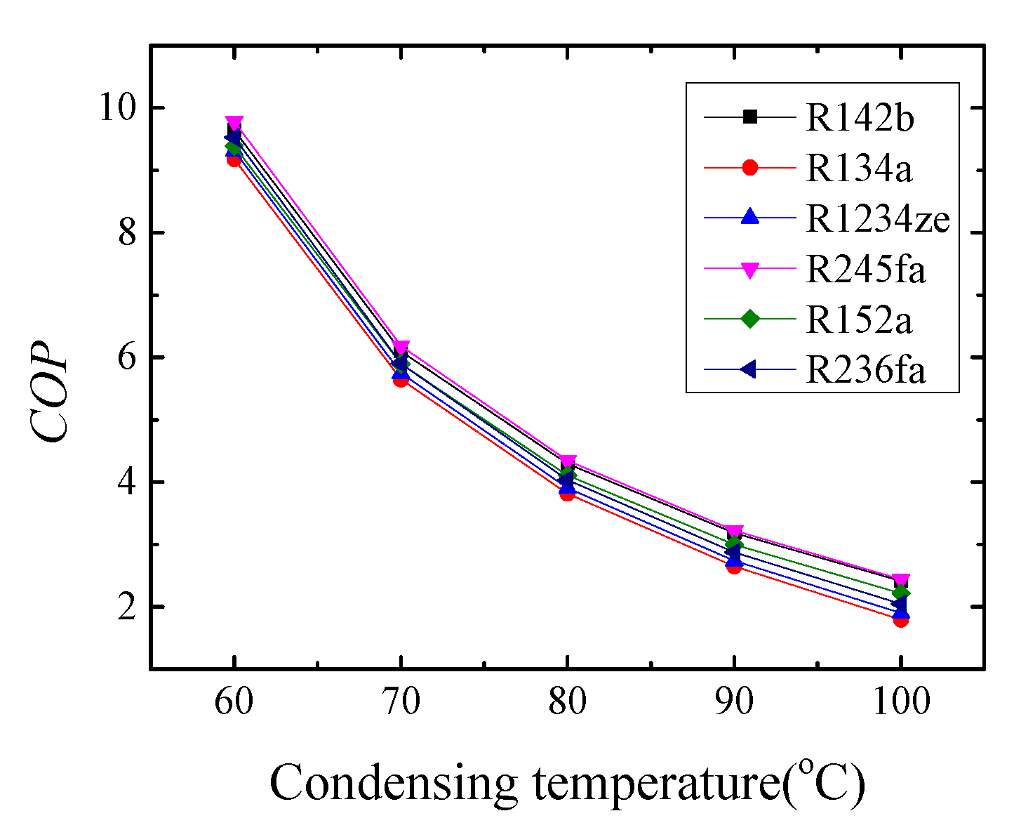
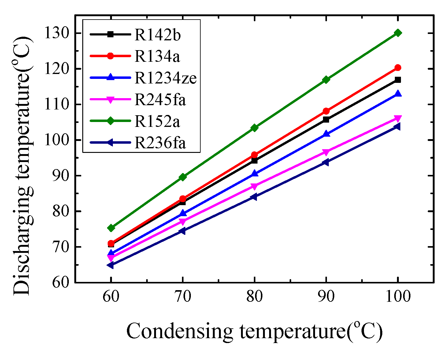
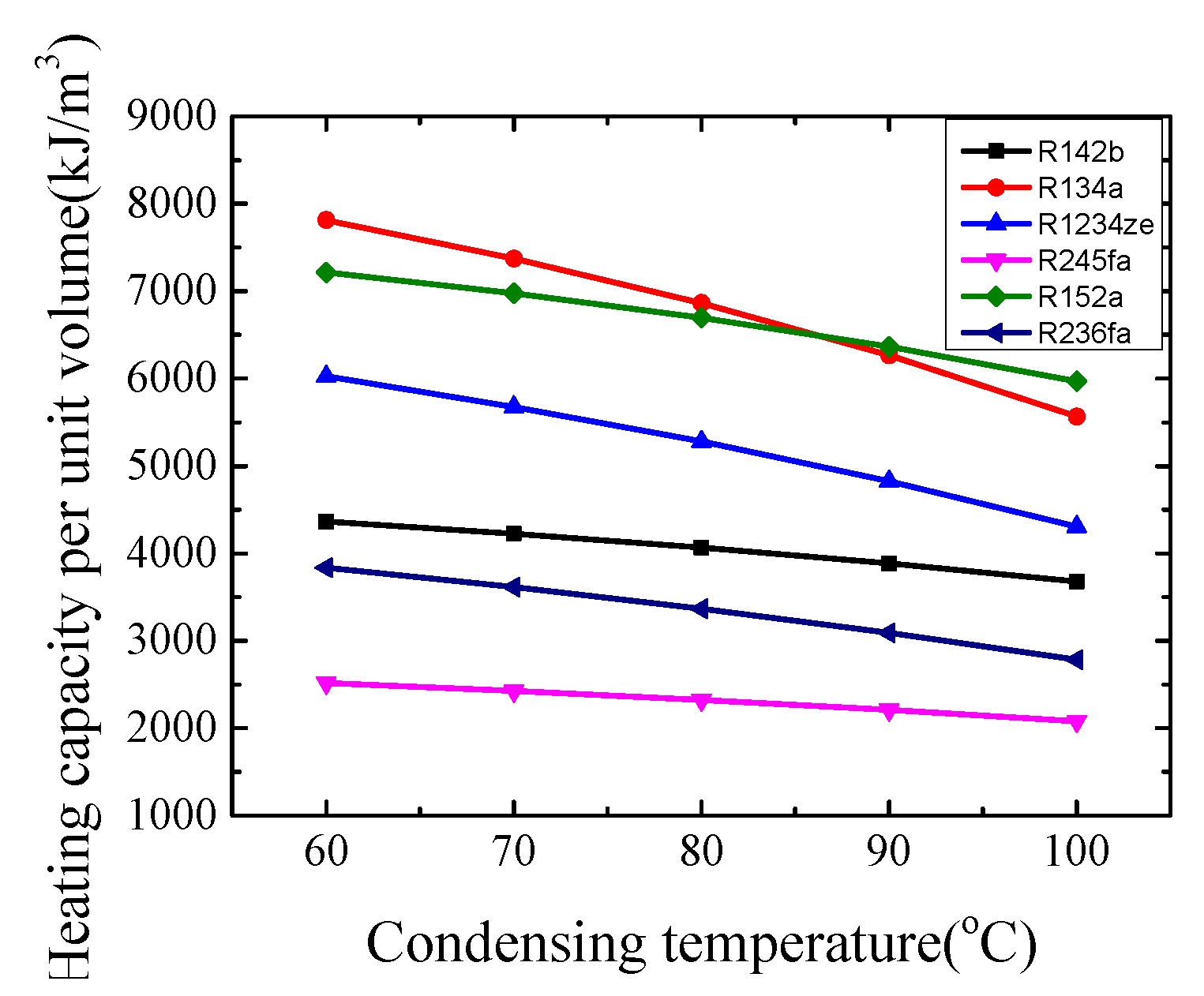
3.1. Selection of the Working Fluid in the Compression Sub-Cycle

COP, heating capacity per unit volume and discharging temperature of different working fluids are compared at different condensation temperatures, as shown in Figure 3, Figure 4 and Figure 5. It is found that R142b and R245fa show better COP, and R134a and R152a better heating capacity, meanwhile, R245fa and R236a show lower discharging temperature, whose temperature difference is less than 5 °C. Considering the significant influence of COP on systematic performance, R245fa is the better working fluid for this compression sub-cycle.
The environmental performance evaluation, which includes ODP (Ozone Depletion Potential) and GWP (Global Warming Potential) of different refrigerants is shown as Table 4 It is clear that R1234ze owns better environmental protection, R152a and R245fa is second, and the other is the worst.
In a word, considering the environmental protection and circulation characteristics, R245fa is selected as the working fluid of the compression sub-cycle.

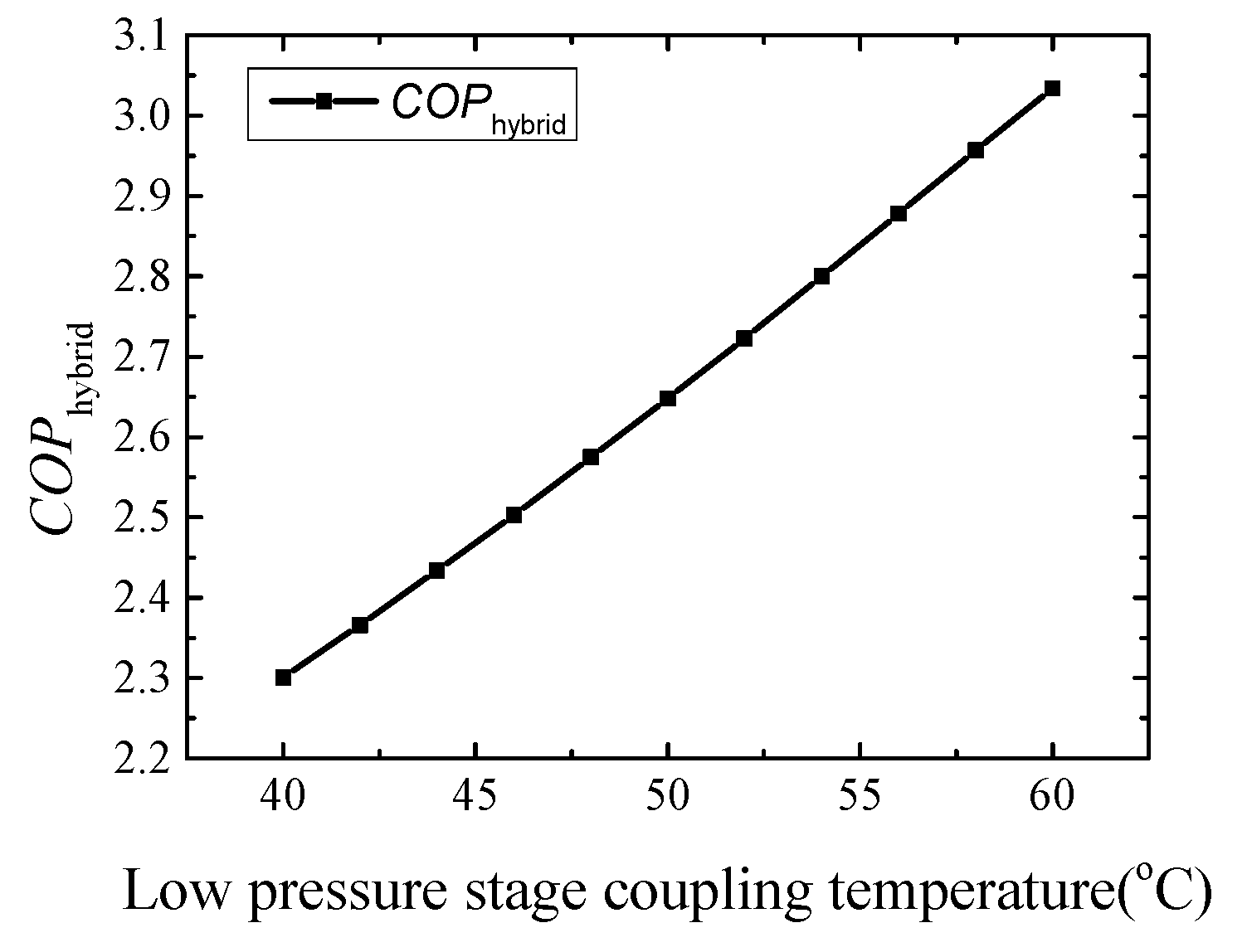
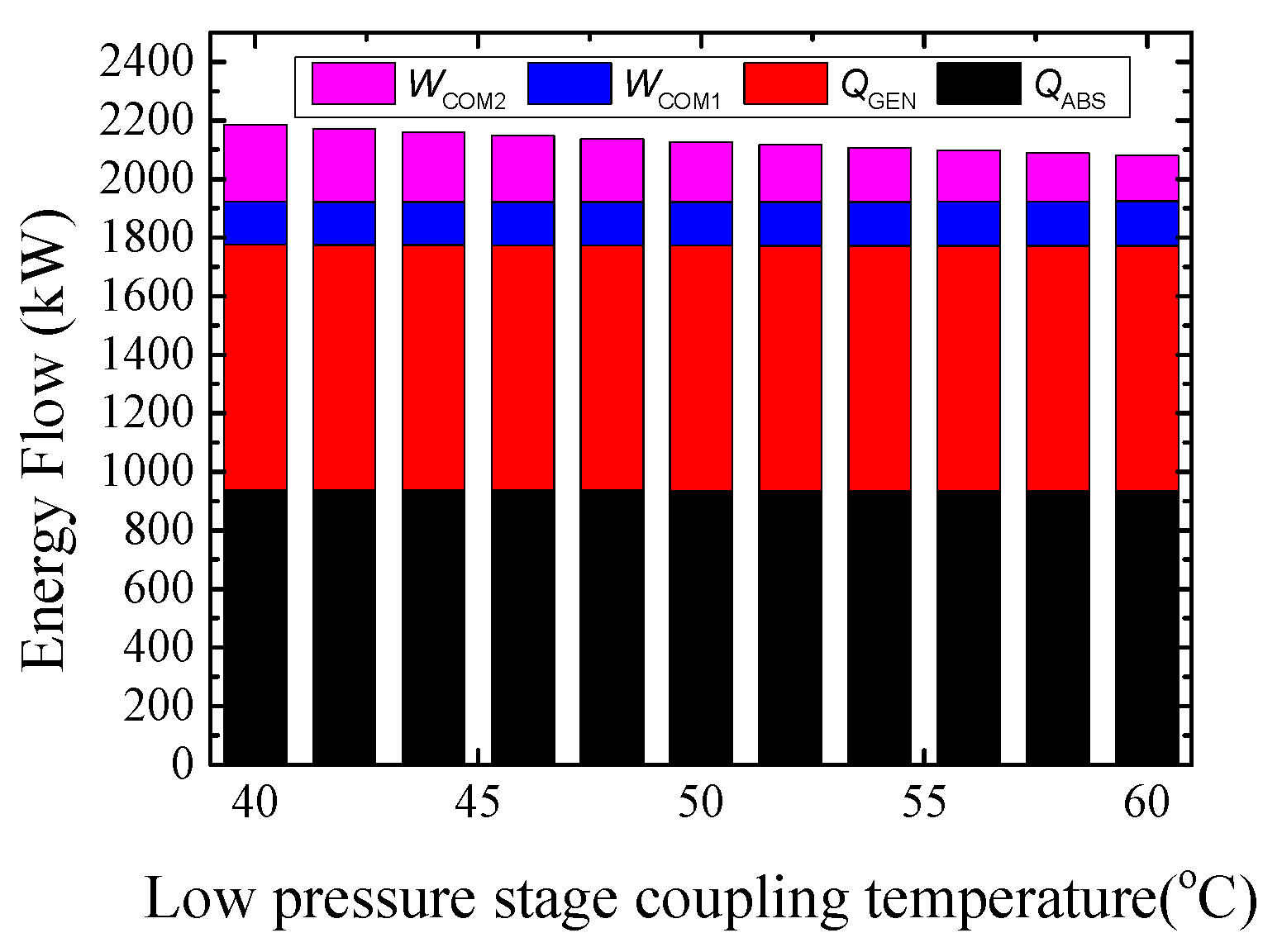
3.2. The Influence of Low Pressure Stage Coupling Temperature on Cycle

The COP of this hybrid cycle changes with the coupling temperature of the low-pressure stage when the coupling temperature of the high-pressure stage is 95 °C and the pressure ratio is 4, as shown in Figure 6. When the low-pressure stage coupling temperature rises from 40 to 60 °C, the COP of the compression sub-cycle changes from 3.28 to 5.53. It can be found that the low-pressure stage coupling temperature shows a greater influence on the compression sub-cycle and the temperature difference between the two sides of the compression sub-cycle decreases when this temperature increases, which could decrease irreversible loss and increase COP directly.
The COP of this hybrid cycle varies with the coupling temperature of the low-pressure stage, as shown in Figure 7. COP of the hybrid cycle increases from 2.30 to 3.03 when the coupling temperature changes from 40 °C to 60 °C, mainly due to the improvement in compression sub-cycle performance.
The energy flow of this cycle is shown in Figure 8. The heating performance decreases from 938.2 kW to 934.4 kW under simulated working cases, when the electrical consumption of absorption sub-cycle compressor increases from 147.1 kW to 152.8 kW and the compressor power consumption in the compression sub-cycle decreases from 260.6 kW to 155.2 kW significantly.

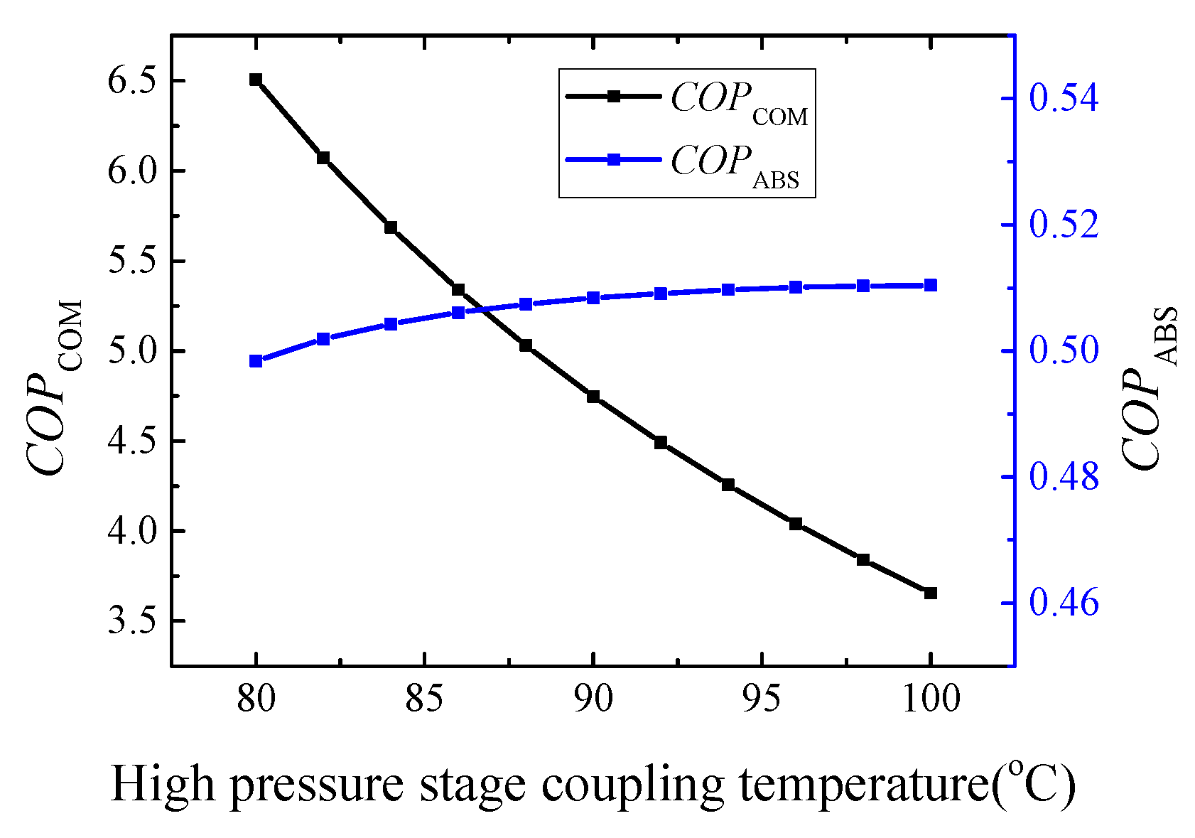
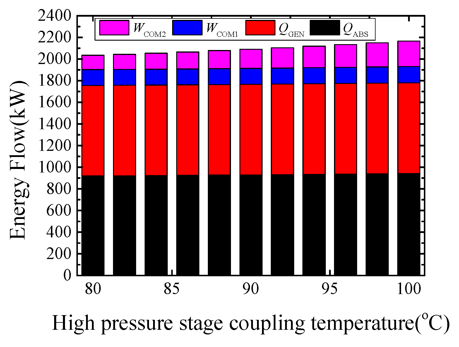
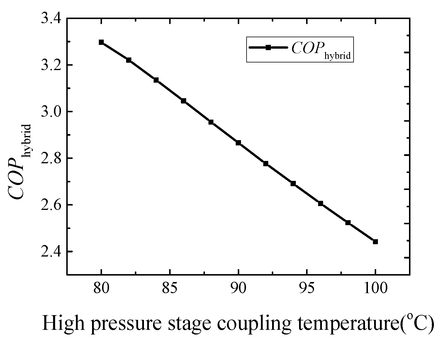
3.3. The Influence of High Pressure Stage Coupling Temperature on Cycle

The relationship of the sub-cycle COP with the coupling temperature of the high-pressure stage when the low-pressure stage coupling temperature is 50 °C and the compressor pressure ratio is 4 is shown in Figure 9. It shows that COP of the compression sub-cycle decreases from 6.51 to 3.66. The reduction of COP of the compression sub-cycle is attributed to the increase in the temperature difference between low and high pressure stages.The relationship of the coupling cycle COP with the high pressure stage coupling temperature is shown in Figure 10. The change of the coupled cycle COP and the change of the compression sub-cycle COP shows a similar trend, which varies from 3.30 to 2.44.
The energy flow of this hybrid cycle is shown in Figure 11. The heating load slightly increases from 918.9 kW to 942.2 kW. Meanwhile, the electrical consumption of the absorption sub-cycle compressor increases slightly from 146.6 kW to 151.3 kW when the generator load is 837.4 kW. The electrical consumption of the compression sub-cycle compressor increases by almost 80%, which varies from 132.1 kW to 234.5 kW.

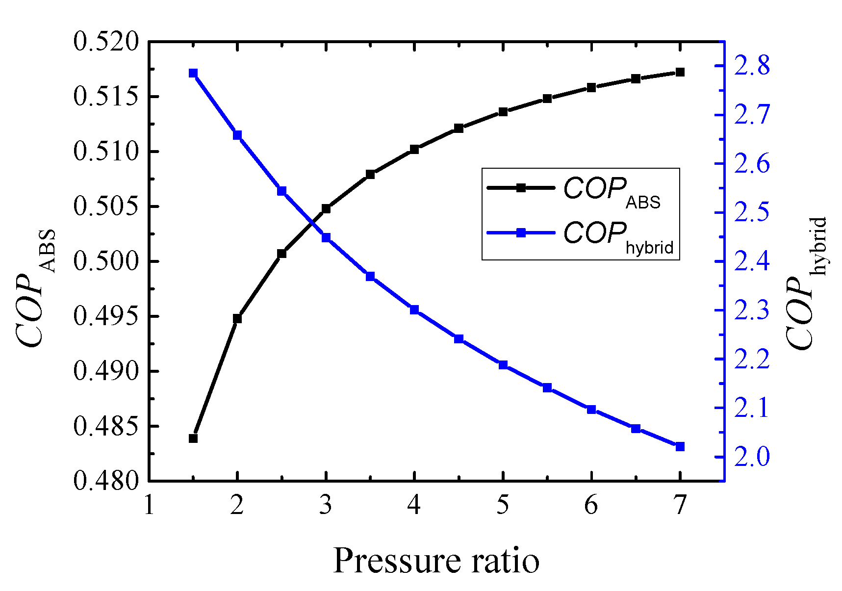
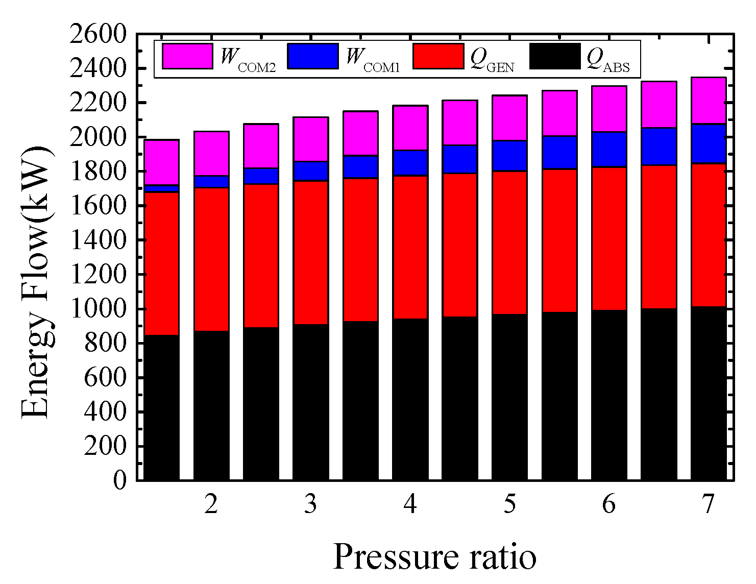
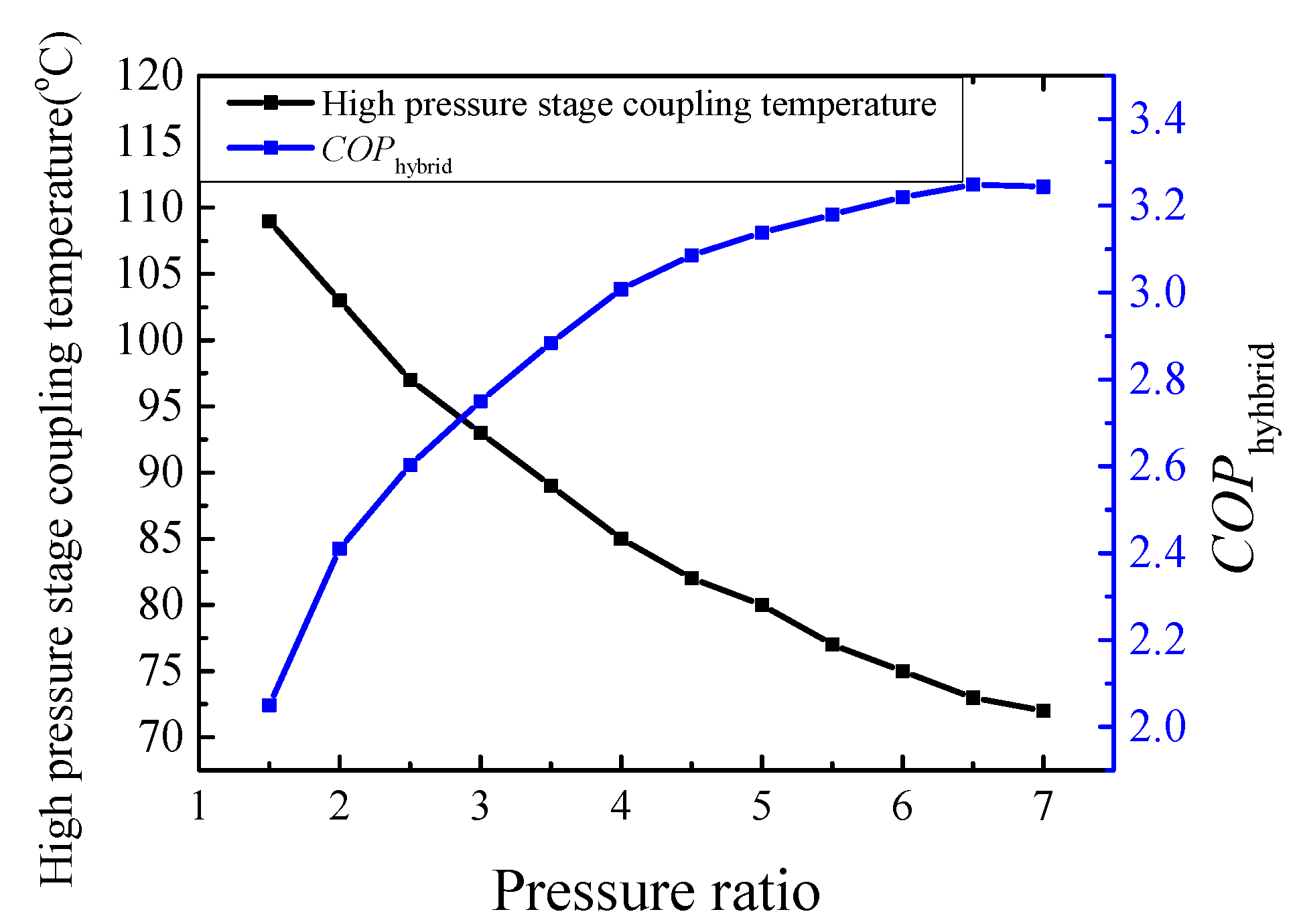
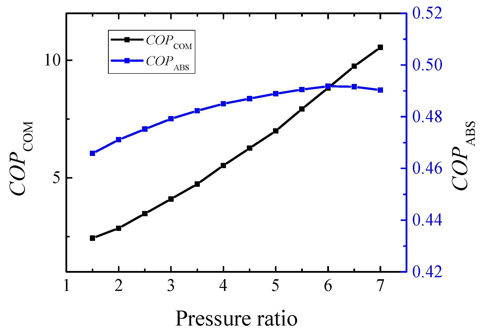
3.4. Influence of Compressor Pressure Ratio

It is found that the COP of the compression sub-cycle remains constant when the coupling temperature of low-pressure stage and high-pressure stage are 40 °C and 95 °C, respectively, while the variation trend of the absorption sub-cycle and coupling cycle COP with the compressor pressure ratio is shown in Figure 12. It shows that the COP of the absorption sub-cycle increases from 0.48 to 0.52, while the hybrid COP decreases from 2.79 to 2.02, which is due to the increase in absorber load and compressor power consumption, but the latter is much more obvious.
The energy flow of this hybrid cycle is shown in Figure 13. It can be found that the heating performance increases from 842.6 kW to 1009 kW. Besides, the generator load is 837.4 kW, and the power consumption of the absorption sub-cycle compressor increases from 38.59 kW to 229.4 kW when the electrical consumption of the compression sub-cycle compressor decreases from 264 kW to 258.6 kW at first, increasing to 270 kW later.

3.5. Optimal Condition of Hybrid Cycle

It is apparent that the best working condition at a certain pressure ratio can be obtained through changing the coupling temperature of the low-pressure stage and the high-pressure stage. The optimal working conditions and the corresponding cycle performance under different pressure ratios are shown in Figure 14 and Figure 15.
The optimal coupling temperatures of the high-pressure stage under different pressure ratios are shown in Figure 14, when the low pressure stage coupling temperature is 55 °C. It can be seen that the coupling temperature of the high-pressure stage decreases from 109 °C to 72 °C. At the same time, the hybrid cycle COP shows firstly an increasing trend and then decreases later, reaching the maximum value of 3.249 when pressure ratio is 6.5.
The application of the compressor can reduce the high-temperature stage coupling temperature effectively. The COP of the compression sub-cycle increases significantly with the decrease in coupling temperature of the high-temperature stage, as shown in Figure 15, while the COP of the absorption sub-cycle shows a trend of increasing firstly and then decreasing later with a maximum COP of 0.49 when the pressure ratio is 6.
In summary, better COP of this cycle is obtained when the pressure ratio is 6.5, the coupling temperature of the low-pressure stage is 55 °C and the coupling temperature of the high-pressure stage is 73 °C.

3.6. Exergy Analysis of Hybrid Cycle

From the point of view of exergy, the energy conversion and loss in the process are analyzed to provide reference for system application and optimization. Under the conditions that the inlet and outlet temperatures of the heat source are 160 °C and 140 °C, and the heat sinks are 180 °C and 200 °C separately, the efficiency of each component is calculated as shown in Table 5. It can be seen that the exergy efficiency of generator, absorber and compressor is much lower, while that of the hybrid heat exchanger is higher relatively, which is due to the small temperature difference in its heat transfer process.

4. Conclusions

In order to reach a heating temperature over 200 °C, this work proposes a new type of coupled heat pump cycle, which is simulated by EES and REFPROP, and the main parameters of the cycle are discussed and optimized. The following conclusions are found:
(1)
Simulation of compression sub cycle with R142b, R134a, R1234ze, R245fa, R152a and R236fa is analyzed, and R245fa is selected, with a higher COP and lower discharging temperature;
(2)
The COP of the coupling cycle increases with the coupling temperature of the low pressure stage when the pressure ratio is 4 and the coupling temperature of the high-pressure stage is 95 °C; the coupling cycle COP increases with the coupling temperature of the high pressure stage when the pressure ratio is 4 and the coupling temperature of the low-pressure stage is 50 °C;
(3)
COP of the coupling cycle decreases with the pressure ratio, and the maximum COP is 2.785 when the pressure ratio is 1.5 when the coupling temperatures of the high-pressure stage and the low-pressure stage are 95 °C and 40 °C;
(4)
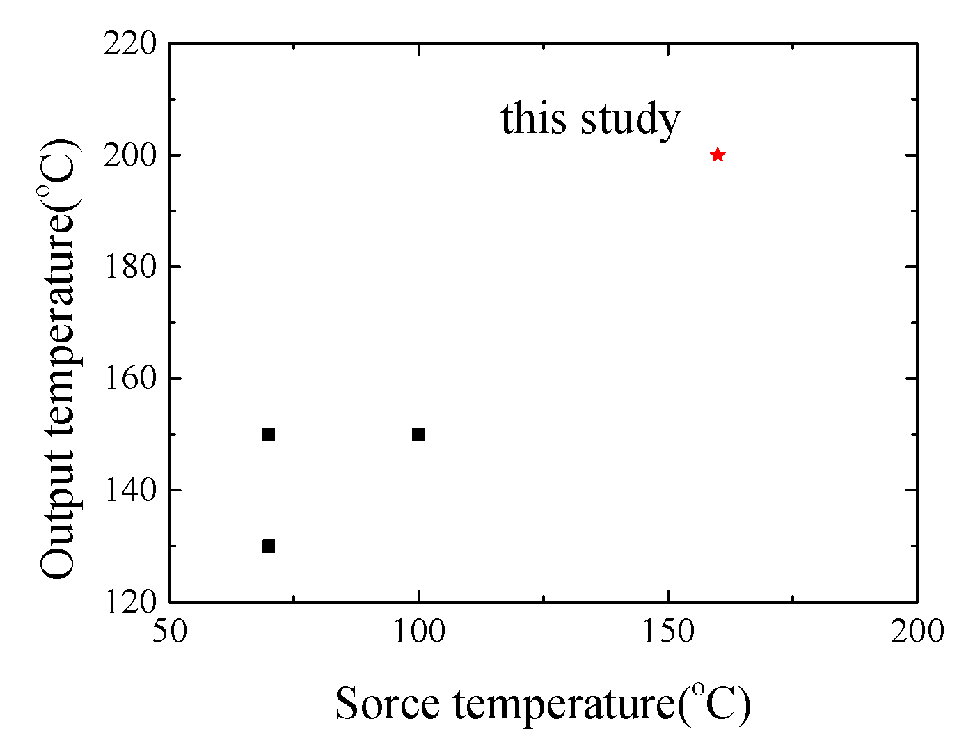
The optimal operating conditions when the heat source temperature is 160 °C and the heat sink temperature is 200 °C are obtained by comparing the optimal operating conditions under different pressure ratios. The COP takes the maximum value 3.249 when the pressure ratio is 6.5, the low-pressure stage coupling temperature is 55 °C and the high-pressure stage coupling temperature is 73 °C. Meanwhile, the simulation results of exergy efficiency under optimal operating conditions show that generator, absorber and compressor should be improved to enhance cycle performance.
(5)
The exergy efficiency of evaporation and condensation is higher due to the small temperature difference in its heat transfer process.
In addition, the heat transfer process of all components will be given to optimize the heat transfer area, reducing equipment size and initial investment, with a sample unit in our next research plan. This new type of heat pump is promising for industrial heat recovery cases, with satisfactory performance.

Author Contributions

Conceptualization and methodology, J.S.; simulation and writing-original draft preparation, Y.W.; visualization, software and investigation, K.W.; writing-review and editing, Z.G.; supervision, Y.Y. All authors have read and agreed to the published version of the manuscript.

Funding

This work was sponsored by National Key Research and Development Program of China (NO. 2019YFE0104900), National Natural Science Foundation of China (No. 52090062), Fundamental Research Funds for the Central Universities (No. 2020MS009).

Data Availability Statement

Not applicable.

Conflicts of Interest

The authors declare no conflict of interest.

Nomenclature

Subscripts Abbreviations
c p specific heat, kJ kg−1 K−1COM2compressor2
hspecific enthalpy, kJ kg−1CON1condenser in the absorption cycle
mmass flow rate, kg s−1CON2condenser in the compression cycle
Qthermal energy, kWEVA1evaporator in the absorption cycle
Wpower, kWEVA2evaporator in the compression cycle
xconcentration, %GENgenerator
ηefficiencyhybridhybrid cycle
ABSabsorberisisentropic
COMcompression cyclerefreference
COM1compressor1COPCoefficient of performance
EESEngineering Equation Solver

References

  1. Green, C. A ‘fair and ambitious’ climate agreement is not nearly enough: Paris 2015 take heed. Environ. Res. Lett. 2015, 10, 101003. [Google Scholar] [CrossRef]
  2. Zhang, J.; Zhang, H.H.; He, Y.L.; Tao, W.Q. A comprehensive review on advances and applications of industrial heat pumps based on the practices in China. Appl. Energy 2016, 178, 800–825. [Google Scholar] [CrossRef]
  3. Kim, J.; Park, S.R.; Baik, Y.J.; Chang, K.C.; Ra, H.S.; Kim, M.; Kim, Y. Experimental study of operating characteristics of compression/absorption high-temperature hybrid heat pump using waste heat. Renew. Energy 2013, 54, 13–19. [Google Scholar] [CrossRef]
  4. Hu, B.; Liu, H.; Wang, R.Z.; Li, H.B.; Zhang, Z.P.; Wang, S. A high-efficient centrifugal heat pump with industrial waste heat recovery for district heating. Appl. Therm. Eng. 2017, 125, 359–365. [Google Scholar] [CrossRef]
  5. Wu, D.; Hu, B.; Wang, R.Z.; Fan, H.B.; Wang, R.J. The performance comparison of high temperature heat pump among R718 and other refrigerants. Renew. Energy 2020, 154, 715–722. [Google Scholar] [CrossRef]
  6. Frate, G.F.; Ferrari, L.; Desideri, U. Analysis of suitability ranges of high temperature heat pump working fluids. Appl. Therm. Eng. 2019, 150, 628–640. [Google Scholar] [CrossRef]
  7. Mateu-Royo, C.; Navarro-Esbrí, J.; Mota-Babiloni, A.; Amat-Albuixech, M.; Moles, F. Theoretical evaluation of different high-temperature heat pump configurations for low-grade waste heat recovery. Int. J. Refrig. 2018, 90, 229–237. [Google Scholar] [CrossRef]
  8. Kosmadakis, G.; Arpagaus, C.; Neofytou, P.; Bertsch, S. Techno-economic analysis of high-temperature heat pumps with low-global warming potential refrigerants for upgrading waste heat up to 150 °C. Energy Convers. Manag. 2020, 226, 113488. [Google Scholar] [CrossRef]
  9. Markmann, B.; Tokan, T.; Loth, M.; Stegmann, J.; Hartmann, K.H.; Kruse, H.; Kabelac, S. Experimental results of an absorption-compression heat pump using the working fluid ammonia/water for heat recovery in industrial processes. Int. J. Refrig. 2019, 99, 59–68. [Google Scholar] [CrossRef]
  10. Azhar, M.; Siddiqui, M.A. Exergy analysis of single to triple effect lithium bromide-water vapour absorption cycles and optimization of the operating parameters. Energy Convers. Manag. 2019, 180, 1225–1246. [Google Scholar] [CrossRef]
  11. Zhang, H.S.; Zhao, H.B.; Li, Z.L. Thermodynamic performance study on solar-assisted absorption heat pump cogeneration system in the coal-fired power plant. Energy 2016, 116, 942–955. [Google Scholar] [CrossRef]
  12. Sun, F.T.; Fu, L.; Sun, J.; Zhang, S.G. A new waste heat district heating system with combined heat and power (CHP) based on ejector heat exchangers and absorption heat pumps. Energy 2014, 69, 516–524. [Google Scholar] [CrossRef]
  13. Wu, W.; Leung, M. A novel hybrid-energy heat pump with refrigerant injection: Performance characterization and injection optimization. Energy Convers. Manag. 2020, 208, 112584. [Google Scholar] [CrossRef]
  14. Cai, D.H.; Jiang, J.K.; He, G.G.; Li, K.Q.; Niu, L.J.; Xiao, R.X. Experimental evaluation on thermal performance of an air-cooled absorption refrigeration cycle with NH3-LiNO3 and NH3-NaSCN refrigerant solutions. Energy Convers. Manag. 2016, 120, 32–43. [Google Scholar] [CrossRef]
  15. Salehi, S.; Yari, M.; Mahmoudi, S.M.S.; Farshi, L.G. Investigation of crystallization risk in different types of absorption LiBr/H2O heat transformers. Therm. Sci. Eng. Prog. 2019, 10, 48–58. [Google Scholar] [CrossRef]
  16. Wu, W.; Zhang, X.L.; Li, X.L.; Shi, W.X.; Wang, B.L. Comparisons of different working pairs and cycles on the performance of absorption heat pump for heating and domestic hot water in cold regions. Appl. Therm. Eng. 2012, 48, 349–358. [Google Scholar] [CrossRef]
  17. Xu, Z.Y.; Gao, J.T.; Mao, H.C.; Liu, D.S.; Wang, R.Z. Double-section absorption heat pump for the deep recovery of low-grade waste heat. Energy Convers. Manag. 2020, 220, 113072. [Google Scholar] [CrossRef]
  18. Sun, J.; Ge, Z.H.; Fu, L. Investigation on LiBr-H2O double evaporation-absorption heat pump (DEAHP) for heat recovery under lower driving sources. Appl. Therm. Eng. 2017, 125, 978–985. [Google Scholar] [CrossRef]
  19. Wu, W.; Shi, W.X.; Wang, B.L.; Li, X.T. Annual performance investigation and economic analysis of heating systems with a compression-assisted air source absorption heat pump. Energy Convers. Manag. 2015, 98, 290–302. [Google Scholar] [CrossRef]
  20. Wu, W.; Wang, B.L.; Shang, S.; Shi, W.X.; Li, X.T. Experimental investigation on NH3–H2O compression-assisted absorption heat pump (CAHP) for low temperature heating in colder conditions. Int. J. Refrig. 2016, 67, 109–124. [Google Scholar] [CrossRef]
  21. Wu, W.; Shi, W.X.; Wang, J.; Wang, B.L.; Li, X.T. Experimental investigation on NH3–H2O compression-assisted absorption heat pump (CAHP) for low temperature heating under lower driving sources. Appl. Energy 2016, 176, 258–271. [Google Scholar] [CrossRef]
  22. Okwose, C.F.; Abid, M.; Ratlamwala, T.A.H. Performance analysis of compressor-assisted two-stage triple effect absorption refrigeration cycle for power and cooling. Energy Convers. Manag. 2021, 227, 113547. [Google Scholar] [CrossRef]
  23. Al-Madhagi, M.A.; Li, S.H.; Iqbal, Q.; Alasri, S. Performance analysis and comparative study of two compression-assisted absorption cycles for heat pump applications. Sustain. Energy Technol. Assess. 2020, 38, 100650. [Google Scholar] [CrossRef]
  24. Wu, W.; You, T.; Li, X.T. Performance comparisons of NH3/ionic liquid absorption–compression heat pump for increasing the utilization of geothermal energy. Int. J. Refrig. 2019, 104, 19–33. [Google Scholar] [CrossRef]
  25. Ji, Q.; Han, Z.W.; Zhang, X.P.; Sun, X.Q.; Li, G.; Li, X.M.; Yang, L.Y. Study on the heating performance of absorption-compression hybrid heat pump in severe cold regions. Appl. Therm. Eng. 2021, 185, 116419. [Google Scholar] [CrossRef]
  26. Wu, W.; Zhai, C.; Huang, S.M.; Sui, Y.R.; Sui, Z.G.; Ding, Z.X. A hybrid H2O/IL absorption and CO2 compression air-source heat pump for ultra-low ambient temperatures. Energy 2022, 239, 122180. [Google Scholar] [CrossRef]
  27. Gao, J.T.; Xu, Z.Y.; Wang, R.Z. Enlarged temperature lift of hybrid compression-absorption heat transformer via deep thermal coupling. Energy Convers. Manag. 2021, 234, 113954. [Google Scholar] [CrossRef]
  28. Gao, J.T.; Xu, Z.Y.; Wang, R.Z. An air-source hybrid absorption-compression heat pump with large temperature lift. Appl. Energy 2021, 291, 116810. [Google Scholar] [CrossRef]
  29. Liu, C.C.; Jiang, Y.C.; Han, W.; Kang, Q.L. A high-temperature hybrid absorption-compression heat pump for waste heat recovery. Energy Convers. Manag. 2018, 172, 391–401. [Google Scholar] [CrossRef]
  30. An, M.Y.; Zhao, X.R.; Xu, Z.Y.; Wang, R.Z. A Hybrid Compression-Absorption High Temperature Heat Pump Cycles for Industrial Waste Heat Recovery. J. Shanghai Jiaotong Univ. 2021, 55, 434–443. [Google Scholar]
Figure 1. High heating temperature of current heat pumps in the literature [6,7,8].
Energies 15 07515 g001
Figure 2. Working processes of the hybrid cycle (a) and the whole cycle in P-t diagram (b).
Energies 15 07515 g002
Figure 3. Comparison of COP among different refrigerants.
Energies 15 07515 g003
Figure 4. Comparison of heating capacity per unit volume among different refrigerants.
Energies 15 07515 g004
Figure 5. Comparison of discharging temperature among different refrigerants.
Energies 15 07515 g005
Figure 6. Effect of low pressure stage coupling temperature on sub-cycle COP.
Energies 15 07515 g006
Figure 7. Effect of low pressure stage coupling temperature on coupling cycle COP.
Energies 15 07515 g007
Figure 8. Effect of low pressure stage coupling temperature on the energy flow.
Energies 15 07515 g008
Figure 9. Effect of high pressure stage coupling temperature on sub-cycle COP.
Energies 15 07515 g009
Figure 10. Effect of high pressure stage coupling temperature on coupling cycle COP.
Energies 15 07515 g010
Figure 11. Effect of high pressure stage coupling temperature on the energy flow.
Energies 15 07515 g011
Figure 12. Effect of pressure ratio on sub-cycle and coupling COP.
Energies 15 07515 g012
Figure 13. Effect of pressure ratio on the energy flow.
Energies 15 07515 g013
Figure 14. Optimal operating conditions and coupling cycle COP under different pressure ratios.
Energies 15 07515 g014
Figure 15. Optimal sub-cycle COP under different pressure ratios.
Energies 15 07515 g015
Table 1. Verification of lithium bromide-water absorption cycle compared to reference [30].
T g /°C T a /°CCOPrefCOP Δ /%
70.51050.48040.49142.29
70.51070.47980.48952.02
70.51090.47910.48671.59
Table 2. Verification of compression cycle compared to reference [28].
T e /°C T c /°CCOPrefCOP Δ /%
0632.92.9692.38
13703.33.2680.97
26783.73.524.86
Table 3. Thermodynamic properties of some important state point.
ParameterValueParameterValue
t0 in absorption cycle/°C71 Q GEN /kW837.4
tk in absorption cycle/°C57 Q ABS /kW964.8
te in compression cycle/°C55 Q CON 1 /kW901.6
tc in compression cycle/°C73 Q EVA 1 /kW861
dr/%70.58WCOM1/kW210.1
da/%67.56WCOM2/kW86.89
Table 4. The ODP and GWP of different refrigerants.
ODPGWP
R142b0.0571980
R134a01300
R1234ze0<1
R245fa0858
R152a0138
R236fa08060
Table 5. Exergy efficiency of components.
GeneratorAbsorberCondenser1-Evaporator2Evaporator1-Condenser2Compressor1Compressor2
ηex0.8080.8720.9430.9780.8170.877
Publisher’s Note: MDPI stays neutral with regard to jurisdictional claims in published maps and institutional affiliations.

