1. Introduction
In internal combustion engine vehicles, the compressor of the air conditioner is powered by the engine. By contrast, batteries are the only power source for electric vehicles (EVs), as electric compressors in EVs are battery-powered. Consequently, lightweight and high-efficiency electric compressors are essential to increasing the mileage of EVs [
1,
2]. Thus, an optimal design for the surface permanent magnet synchronous motor (SPMSM) is required because it is the main component of an electric compressor. Recently, the Taguchi method, response surface method (RSM), and genetic algorithm (GA) method have been applied to the optimal design of motors in electric compressors [
3,
4,
5].
The Taguchi method and RSM are surrogate model-based optimization methods that generate a response surface through a relatively small number of analysis points. The designer can proceed with the optimal design relatively quickly by selecting a desired point on the response surface. However, since this is not a point directly analyzed, but generated through the trend of the analysis points, there is an error in those with non-linear characteristics. In addition, it is difficult to derive the global optimal point, so it depends on the experience of the designer. GAs are stochastic algorithms that repeat the generation in the direction that satisfies the objective function based on the initial points. Generation is a sequence of selection, crossover, mutation. Points close to the objective function are selected, and new points are created by crossing the selected points. It also preserves diversity through mutation. It has a high global optimization capability but requires several analysis points. Subsequently, it leads to a long optimization time [
6]. Therefore, there is a need for a method that reduces the optimization time while maintaining global optimization capabilities; a combination of analytical methods and stochastic algorithms could be the appropriate solution [
7].
This study proposed a multi-objective optimal-design method for SPMSMs in electric compressors. A non-dominated sorting GA (NSGA-II) was applied to find a Pareto front, and an analytical method was applied to solve the time-consumption problem of Pareto optimization.
To verify the proposed method, it was applied to the optimal design of an SPMSM for an EV air-conditioner compressor. The optimal design results were compared with those of initial models. In addition, the experimental results of the initial models were presented.
2. Analytical Method
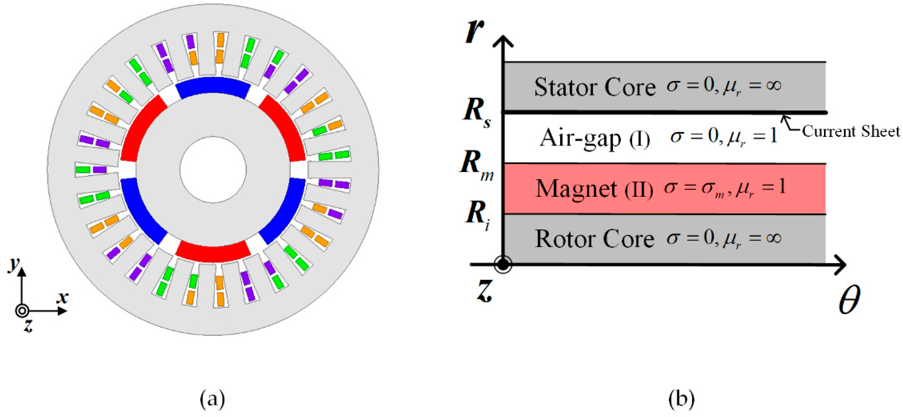
Figure 1 shows the SPMSM for an EV air conditioner compressor.
Figure 1a depicts the actual shape of the SPMSM, which, through several assumptions, can be simplified to the analytical model shown in
Figure 1b. The assumptions for the analytical model are as follows [
8,
9]:
The end effects are negligible;
The magnetic flux density only has radial and tangential components;
The stator and rotor cores have infinite permeability;
The relative permeability of permanent magnet (PM) is the same as that of air;
The slotting effect is accounted for using Carter’s coefficient.
Generally, the relative permeability of rare-earth PMs is almost the same as that of air, and the effect of the end region is negligible, except for super-high-speed motors or special circumstances. To prevent torque saturation, the iron core of the motor is typically designed so as not to be saturated. Therefore, it is reasonable to assume that the iron core has an infinite permeability. Finally, assuming that the magnetic flux density has only radial and tangential components, the magnetic vector potential has only a z component.
2.1. Magnetic Field Solution
The governing equations of the magnetic vector potential A are presented in (1), and (2) for each region of the analytical model in
Figure 1b; for region I, it is Laplace′s equation, and for region II, it is Poisson′s equation.
The magnetization of the PM, represented by
M, is expressed in (3), and (4) as a Fourier series according to the magnetization direction, where
n,
q,
Mp,
Mr, and
θ represent the harmonic order, PM pole pair, parallel, and radial magnetization, and rotor reference angle, respectively.
The components of the magnetic flux density are derived using the relationship between the magnetic vector and the potential, as presented in (5).
where
Br,
Βθ represent radial, and tangential flux density, respectively. Finally, the unknown coefficient is derived from the boundary conditions, as shown in (6), and (7).
The magnetic flux density deduced through the governing equation and boundary conditions are as follows:
where
r,
Cn1,
Cn2,
Dn1, and
Dn2 represent the harmonics, radius from the center, and undetermined coefficient, respectively.
Since the permeability is assumed to be infinite, there is no tangential flux density in the stator core. Therefore, flux linkage can be derived by integrating
Br as much as the coil pitch. The flux linkage is as follows:
where
ay,
by represent the in and out positions of the coil.
r,
α,
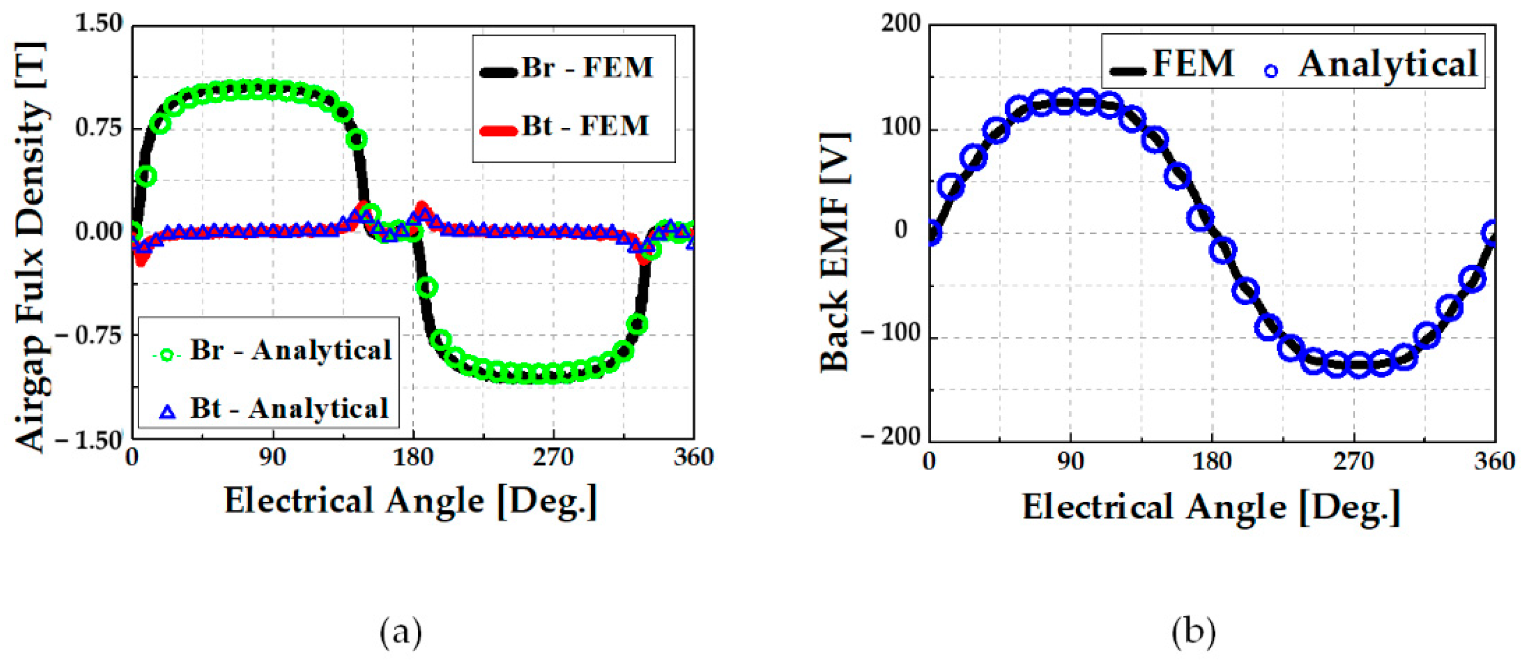
la represent radius from center, stator reference angle, and stator axial length, respectively. The back EMF can be calculated through Faraday’s law.
Figure 2 compares the air gap magnetic flux density and back EMF derived through the analytical method with FEM.
As for the magnetic flux density induced by armature reaction, both regions I and II in the analytical model are assumed to be air. Similarly, for PM magnetization
M, the current of the stator 3-phase coil is modeled as line current density
J expanded as Fourier series in (10), where
m represents the phase number.
The boundary condition for the armature reaction field is as follows:
2.2. Copper Loss
To set the efficiency as objective function of optimization, the motor losses should be calculated. The DC copper loss is expressed in (12), where
Rph and
Iphrms are the phase resistance and RMS phase current, respectively.
Except for super-high-speed motors or motors that use rectangular-type wires, the motor copper loss is a DC loss. Generally, motors use stranded wires, which makes the skin-effect negligible. Therefore, this study only deals with DC loss.
2.3. Core Loss
The core loss equation is expressed as follows [
10,
11]:
where
Kh,
Kc, and
Ke denote the hysteresis, eddy current, and excess loss coefficients, respectively. These coefficients are obtained from experimental data provided by electrical steel manufacturers.
Bm represents the
mth harmonic of the magnetic flux density. The stator can be divided into teeth and yoke areas. Since the teeth and yoke are distributed symmetrically according to the number of slots, the core loss can be calculated by substituting
B after deriving the magnetic flux density for one tooth and the yoke.
Figure 3a depicts the magnetic flux flow in the stator. The flux flowing through the teeth region flows through the yoke region. The flux linkage to the teeth can be obtained by integrating the air-gap flux density with respect to the tooth angle. As the ratio of magnetic flux flowing through the teeth to the magnetic flux flowing through the yoke is constant, based on pole slot combination, the magnetic flux density of the yoke can be obtained using TYratio.
Figure 3b shows the FEM and analytical results of the flux according to the rotor position. Analytical teeth flux provides accurate results with the FEM. The yoke flux can be calculated by multiplying the teeth flux with 1.62. In this model, (6p27s) the TYratio is 1.62.
2.4. Eddy Current Loss
The eddy current lo
Peddy flowing in the PM can be derived by substituting the eddy current density, expressed in (14), into (15) [
12].
where
Je, σm,
Ie, and
Rpm represent the eddy current density, conductivity of the PM, eddy current RMS value, and PM electrical resistance, respectively.
Js is the RMS value of the eddy current per pole pair,
S is the surface of eddy current flow, and
la is the PM axial length. The PM eddy current loss can be calculated by substituting the analytically calculated
AI into the eddy current equation.
3. Optimal Design Process
The SPMSM generates only a magnetic torque because there is no difference in inductance between the d- and q-axes. The magnetic torque is expressed in (16) as follows [
13]:
where
kw,
Bg1,
ac,
Dg,
Lstk, represent the winding factor, flux density per pole, electrical loading, rotor outer diameter, rotor axial length, respectively. The pole-slot combination and winding layout selection are the first stages of motor design. Generally, these stages are determined based on the design specifications. Subsequently, the winding coefficient is automatically determined. The magnetic torque consists of three components: electric loading, magnetic loading, and rotor size. Therefore, the design of an SPMSM is determined mainly by the selection of each component. However, such selection is challenging because each component influences the others.
To solve this problem, this study establishes a method for designing a stator based on a given rotor specification and then optimizes it by selecting the rotor specification through NSGA-II.
3.1. Stator Design Based on a Given Rotor
Figure 4 depicts the conceptual diagram of a rotor and stator of an inner rotor motor.
,
,
,
represent the rotor outer and inner diameter, electric angle of 180 degrees, and the angle of occupied by the pole, respectively. Given the rotor specifications, the magnetic loading and rotor size are determined automatically. Therefore, the only remaining component is the stator (electric loading). The first step in designing a stator is to select the number of coil turns, represented by
Nc. According to the voltage limit,
Nc is calculated using (17), where
Efmax,
Φfmax, and
we represent the back-EMF 1st wave, flux-linkage 1st wave, and electric angular speed, respectively.
The phase current required to generate the rated torque,
Tre, is determined from (18). The teeth thickness
Tt, yoke thickness
Ty, and rotor core thickness
Trc are determined from (19)
where
Φtmax and
Φp represent the peak value of magnetic flux in the teeth and the magnetic flux per pole, respectively.
Btm and
Brc are the tooth and rotor core saturation limits, respectively, which are set at 1.4–1.5 [T] to prevent stator saturation. As mentioned in Section II, the magnetic flux through the teeth and yoke has a constant ratio according to the pole-slot combination. Therefore, multiplying TYratio by the teeth thickness determines the thickness of the yoke, which has the same saturation level as that of teeth.
The last stage of stator design is to determine the teeth length
Hs2, which can be calculated using the slot fill factor limit
Ksf and current density limit
Jlim.
Acu is the coil area that satisfies the current-density limit.
Adw is the area of a strand. Using (20), the number of strands,
nsn is determined.
Asr is the slot area required to satisfy the slot fill factor limit. By substituting Asr to (21), the teeth length Hs2 is determined.
3.2. NSGA—II
Motors have trade-off characteristics because they have various constraints and specifications. For example, when more current is applied to increase the power density, copper loss increases and the stator saturates, which may lower the efficiency. Those with trade-off characteristics can be optimally designed through the Pareto-front, which can be derived through multi-objective genetic algorithm (MOGA).
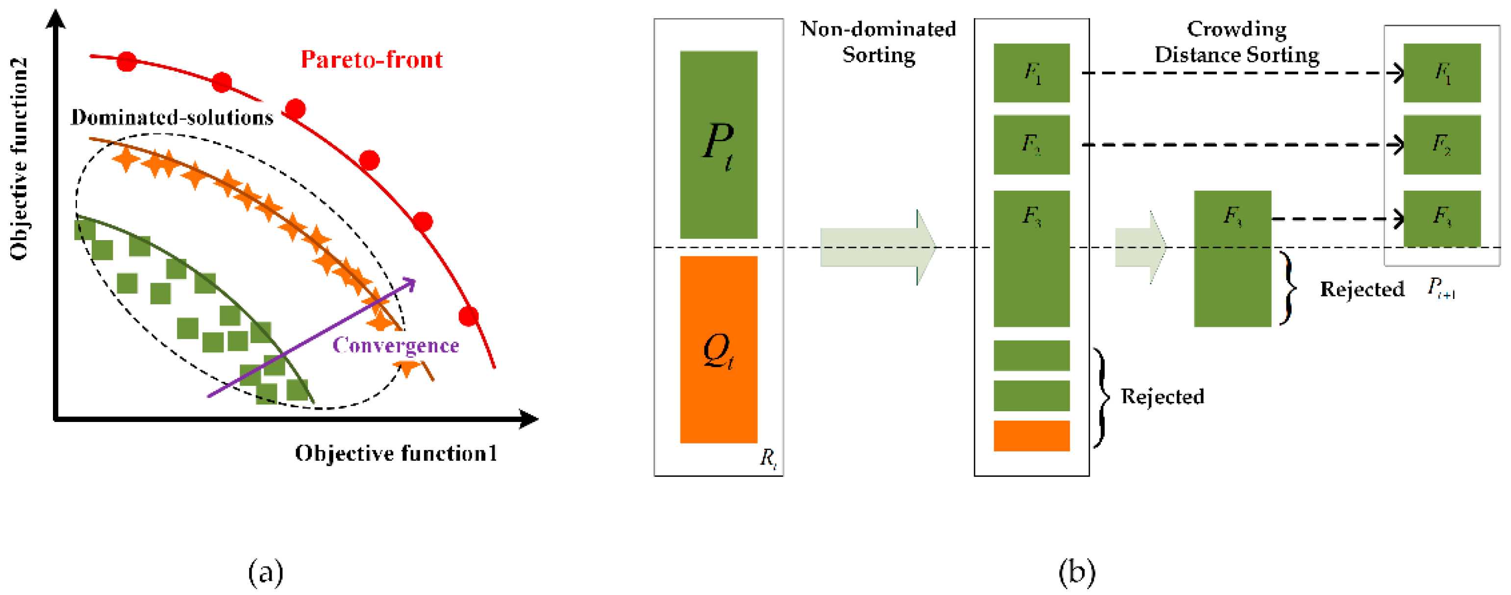
MOGA is an algorithm with high global solution search capability. It repeats generations—selection, crossover, mutation—to become closer to the objective function.
Figure 5a shows that the more generations are repeated, the more analysis points are created to fit the specified objective function. Pareto optimization is a method used in multi-objective optimization to determine the frontier of non-dominated optimal points, where each objective function cannot be improved without degrading other objective function.
The NSGA-II is a type of MOGA proposed by K.Deb [
14]. As shown in
Figure 5b, it classifies analysis points by section through non-dominated sorting, and calculates the distance between analysis points through crowing distance sorting. After that, by prioritizing the separated sections with low density and close to the objective function, the optimization time is shortened and the diversity of solutions is maintained.
Herein, the NSGA-II was applied to select the optimal rotor specification and derive the Pareto front of the motor efficiency, power density with the PM consumption, and back-EMF THD as constraints.
Since the method of designing the stator based on a given rotor specification has been established, the tooth linkage flux and back EMF are derived by applying the rotor specification as pole arc ratio, magnet thickness, rotor outer diameter, and rotor axial length, and using these values to design the stator, SPMSM can be designed.
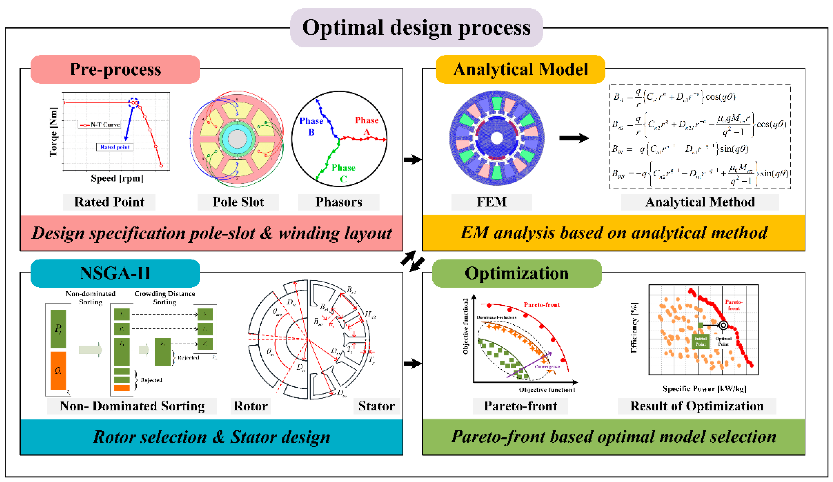
3.3. Flowchart of the Proposed SPMSM Optimal Design
Figure 6 shows a flowchart of the proposed SPMSM optimal design method. It consists of four stages: pre-processing, analytical modeling, NSGA-II, and optimization.
- -
Pre-process
At this stage, the designer determines the pole-slot combination and winding layout with respect to design specifications such as the load profile, rated speed, and size limitation. This study assumed this step to have already been completed.
- -
Analytical model
At this stage, an analytical model is built to design a stator that satisfies the design specifications based on the given rotor specifications. Several characteristics, such as the output torque, PM consumption, back-EMF THD, power density, electromagnetic loss, and efficiency of the designed motor, are analyzed. Here, if a designed model does not satisfy the design specification, a penalty is assigned so that NSGA-II determines whether it is an infeasible model.
- -
NSGA-II
At this stage, four variables representing the rotor specification–rotor out diameter, rotor axial length, PM thickness, and PM embrace– become the variables of NSGA-II. NSGA-II creates new rotor variables that satisfy the objective function with each generation. The generated rotor variables are transmitted to the analytical model stage to derive electromagnetic characteristic values and stator specifications. After that, the objective functions calculated by the analytical model are transferred to the NSGA-II to derive the Pareto front. This process is repeated until the maximum number of algorithm iterations set by the designer is achieved. Usually, because this process requires several analysis points, it takes a significant amount of time when using FEM. However, in this study, the analysis time was almost negligible because it was analyzed using an analytical model.
- -
Optimization
At this stage, the optimal model is selected from the derived Pareto front. All models existing on the Pareto front can be optimized and determined by the motor characteristics, which are more important.
3.4. Verification
To verify the proposed method, it was applied to design a 4.5 [kW] SPMSM for an EV air conditioner compressor. The design specifications are listed in
Table 1. Since the cooling method was refrigerant-integrated cooling, it had a high current density limit.
Specific power, back-EMF THD, efficiency, and PM consumption were selected as the objective functions. The NSGA-II maximum number of iterations and the population were set to 100 and 300, respectively.
Therefore, the total number of analysis points was 30,000.
Figure 7 shows the Pareto front of the power density, efficiency. The optimal model selection criteria were as follows: maintaining the efficiency, increasing the output density, reducing the back-EMF THD, and reducing the PM consumption. Compared to the initial model results, the back-EMF THD and PM consumption decreased by 10.2% and 17.1%, respectively, the power density increased by 9.09%, and the efficiency remained unchanged, as shown in
Figure 8b.
Table 2 lists the initial and optimal model results in comparison with those of the FEM. In initial and optimal model, because the error of the back-EMF fundamental wave is −0.31%, and 2.94%, the current error for the required torque is 2.24%, and −0.67%. The back-EMF THD analysis results of the optimal model tend to decrease compared to the initial model. Moreover, the efficiency has an error of 0.11% and 0.2%, respectively. As most of the errors are within 5%, the proposed method is considered valid. In addition, it was confirmed that the analysis time was significantly reduced.
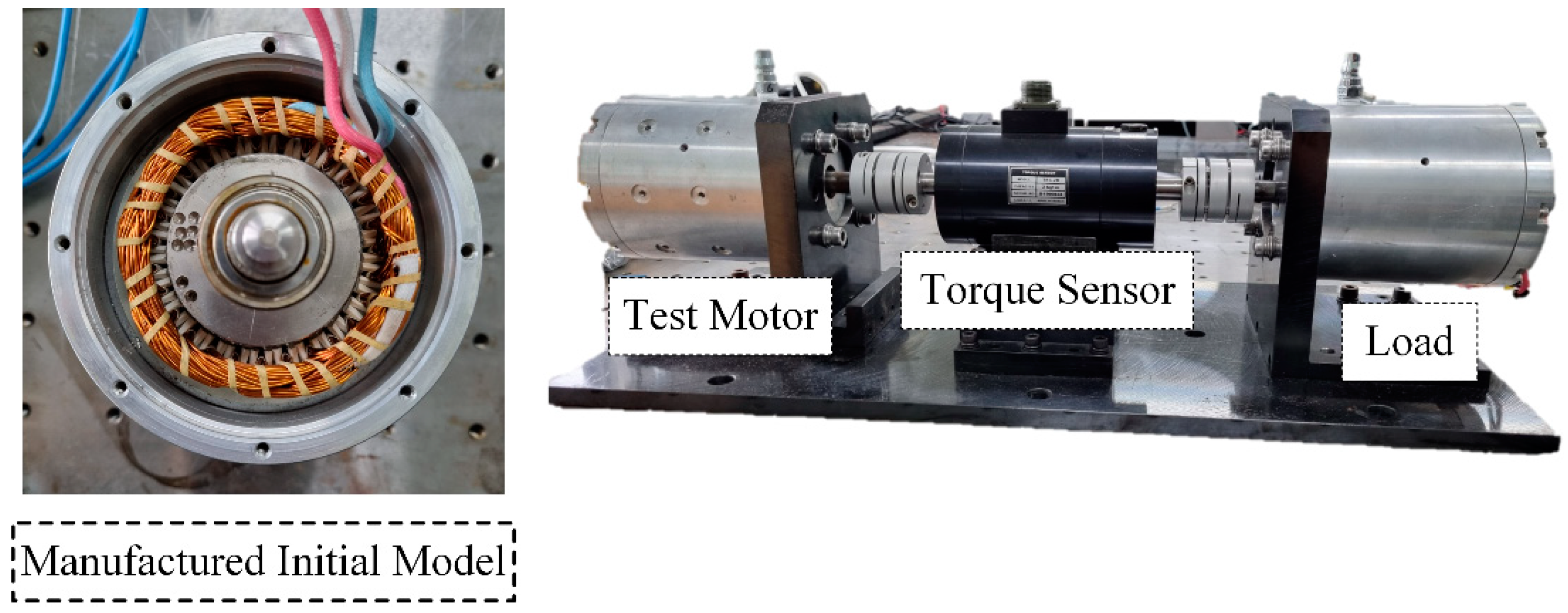
4. Prototype Experiment
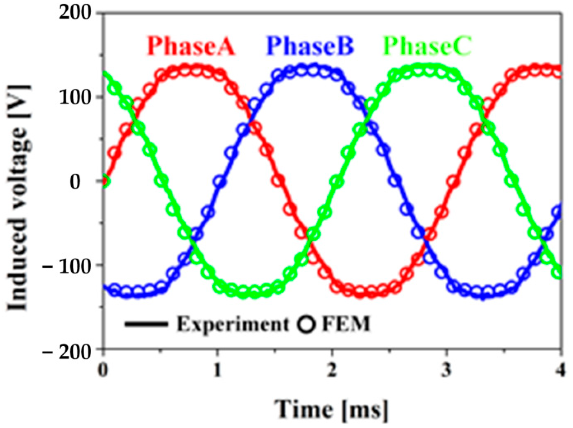
Figure 9 shows the manufactured initial model and test set. The experiment was performed using a generator connected to the opposite shaft of the test motor as a load. As shown in
Figure 10, the back-EMF experimental results agree with the FEM analysis results.
Table 3 lists the results of the efficiency tests under the rated operating conditions. The error rate of the efficiency was approximately 4%, and this error was attributed to two factors.
First, the current density of the initial model was 16 Arms/mm2, and the cooling method was a compressor-integrated refrigerant cooling method. However, in this experiment, only air cooling was performed, owing to the limitation of the test set. Therefore, the copper loss increased owing to an increase in the winding temperature. Second, based on the abnormal noise during no-load operation in the used bearing, it could be assumed that the mechanical loss owing to the bearing was larger than in the general case. Additionally, distinct from the sinusoidal current analysis, in reality, harmonic currents are generated due to the inverter, reducing torque and increasing electromagnetic losses. Thus, the efficiency decreases.
5. Conclusions
This study proposed a multi-objective optimal design method for an SPMSM using NSGA-II and an analytical method.
First, flux linkage and back EMF were derived through rotor variables. After that, the stator was designed within the constraints and required specifications, and the electromagnetic characteristics of the motor were calculated and transmitted to NSGA-II. Based on the values, NSGA-II repeats the generations and creates a Pareto-front, a set of optimal points.
By applying the proposed method to the optimal design of SPMSM for EV air conditioner compressor, the efficiency was maintained while reducing the PM consumption by 17.1% and back EMF THD by 10.2%. In addition, when considering the stator, rotor core, winding, and PM parts of the motor, the power density has been improved by 9.09%. In addition, it was confirmed that the analysis time through the analytical method was significantly less than that of the FEM as 2 s.
Finally, the proposed method was verified by comparing the optimal design results with those of the FEM and the initial model.
Author Contributions
J.-Y.C.: conceptualization, review, and editing; S.-T.J.: original draft preparation and analysis; W.-H.K.: experiment and co-simulation; Y.-K.L.: co-simulation; Y.-J.K.: review, and editing. All authors have read and agreed to the published version of the manuscript.
Funding
This work was supported by the National Research Foundation of Korea (NRF) grant funded by the Korea government (MSIT): 2020R1A2C1007353; This work was supported by Korea Institute of Planning and Evaluation for Technology in Food, Agriculture, Forestry (IPET) through Eco-friendly Power Source Application Agricultural Machinery Technology Development Program, funded by Ministry of Agriculture, Food and Rural Affairs (MAFRA) (322046-03).
Data Availability Statement
Not applicable.
Conflicts of Interest
The authors declare no conflict of interest.
References
- Cho, S.; Jung, K.; Choi, J. Design Optimization of Interior Permanent Magnet Synchronous Motor for Electric Compressors of Air-Conditioning Systems Mounted on EVs and HEVs. IEEE Trans. Magn. 2018, 54, 8204705. [Google Scholar] [CrossRef]
- Zhang, S.; Zhang, T.; Chen, W.; Ji, H. The Development Direction of Electric Air Compressor for Vehicle. In Proceedings of the 2020 3rd International Conference on Advanced Electronic Materials, Computers and Software Engineering (AEMCSE), Shenzhen, China, 24–26 April 2020; pp. 720–722. [Google Scholar]
- Jolly, L.; Jabbar, M.A.; Qinghua, L. Design optimization of permanent magnet motors using response surface methodology and genetic algorithms. IEEE Trans. Magn. 2005, 41, 3928–3930. [Google Scholar] [CrossRef]
- Han, K.; Cho, H.; Cho, D.; Jung, H. Optimal core shape design for cogging torque reduction of brushless DC motor using genetic algorithm. IEEE Trans. Magn. 2000, 36, 1927–1931. [Google Scholar] [CrossRef]
- Raminosoa, T.; Blunier, B.; Fodorean, D.; Miraoui, A. Design and Optimization of a Switched Reluctance Motor Driving a Compressor for a PEM Fuel-Cell System for Automotive Applications. IEEE Trans. Ind. Electron. 2010, 57, 2988–2997. [Google Scholar] [CrossRef]
- Gao, J.; Dai, L.; Zhang, W. Improved genetic optimization algorithm with subdomain model for multi-objective optimal design of SPMSM. CES Trans. Electr. Mach. Syst. 2018, 2, 160–165. [Google Scholar] [CrossRef]
- Kim, W. Multi-Objective Optimal Design of SPMSM for Electric Compressor Using Analytical Method and NSGA-II Algorithm. Master’s Thesis, Chungnam National University, Daejeon, Korea, 2022. [Google Scholar]
- Lee, H.-K.; Shin, K.-H.; Bang, T.-K.; Nah, J.-H.; Choi, J.-Y. Experimental Verification and Analytical Study of Influence of Rotor Eccentricity on Electromagnetic Characteristics of Permanent Magnet Machine. IEEE Trans. Appl. Supercond. 2020, 30, 5202605. [Google Scholar] [CrossRef]
- Jang, G.; Koo, M.; Kim, J.; Choi, J. Analysis of Eddy Current Loss in Permanent Magnet Linear Synchronous Generator Considering Tapped Holes in Movers Using Semi-3-D Analytical Method. IEEE Trans. Magn. 2017, 53, 1–5. [Google Scholar]
- Shin, K.-H.; Hong, K.; Cho, H.-W.; Choi, J.-Y. Core Loss Calculation of Permanent Magnet Machines Using Analytical Method. IEEE Trans. Appl. Supercond. 2018, 28, 1–5. [Google Scholar] [CrossRef]
- Tarımer, İ.; Arslan, S.; Güven, M.E. Investigation for Losses of M19 and Amorphous Core Materials Asynchronous Motor by Finite Elements Methods. Electron. Electr. Eng. 2012, 18, 15–18. [Google Scholar] [CrossRef][Green Version]
- Dubas, F.; Rahideh, A. Two-Dimensional Analytical Permanent-Magnet Eddy-Current Loss Calculations in Slotless PMSM Equipped with Surface-Inset Magnets. IEEE Trans. Magn. 2014, 50, 54–73. [Google Scholar] [CrossRef]
- Hendershot, J.R.; Miller, T.J.E. Design of Brushless Permanent Magnet Machines; Motor Design Books: Venice, FL, USA, 2010. [Google Scholar]
- Deb, K.; Pratap, A.; Agarwal, S.; Meyarivan, T. A fast and elitist multiobjective genetic algorithm: NSGA-II. IEEE Trans. Evol. Comput. 2002, 6, 182–197. [Google Scholar] [CrossRef]
| Publisher’s Note: MDPI stays neutral with regard to jurisdictional claims in published maps and institutional affiliations. |
© 2022 by the authors. Licensee MDPI, Basel, Switzerland. This article is an open access article distributed under the terms and conditions of the Creative Commons Attribution (CC BY) license (https://creativecommons.org/licenses/by/4.0/).


