
Novel Multi-Physics Computational Simulation of a 10 kW Permanent Magnet Motor for Podded Propulsion


Abstract
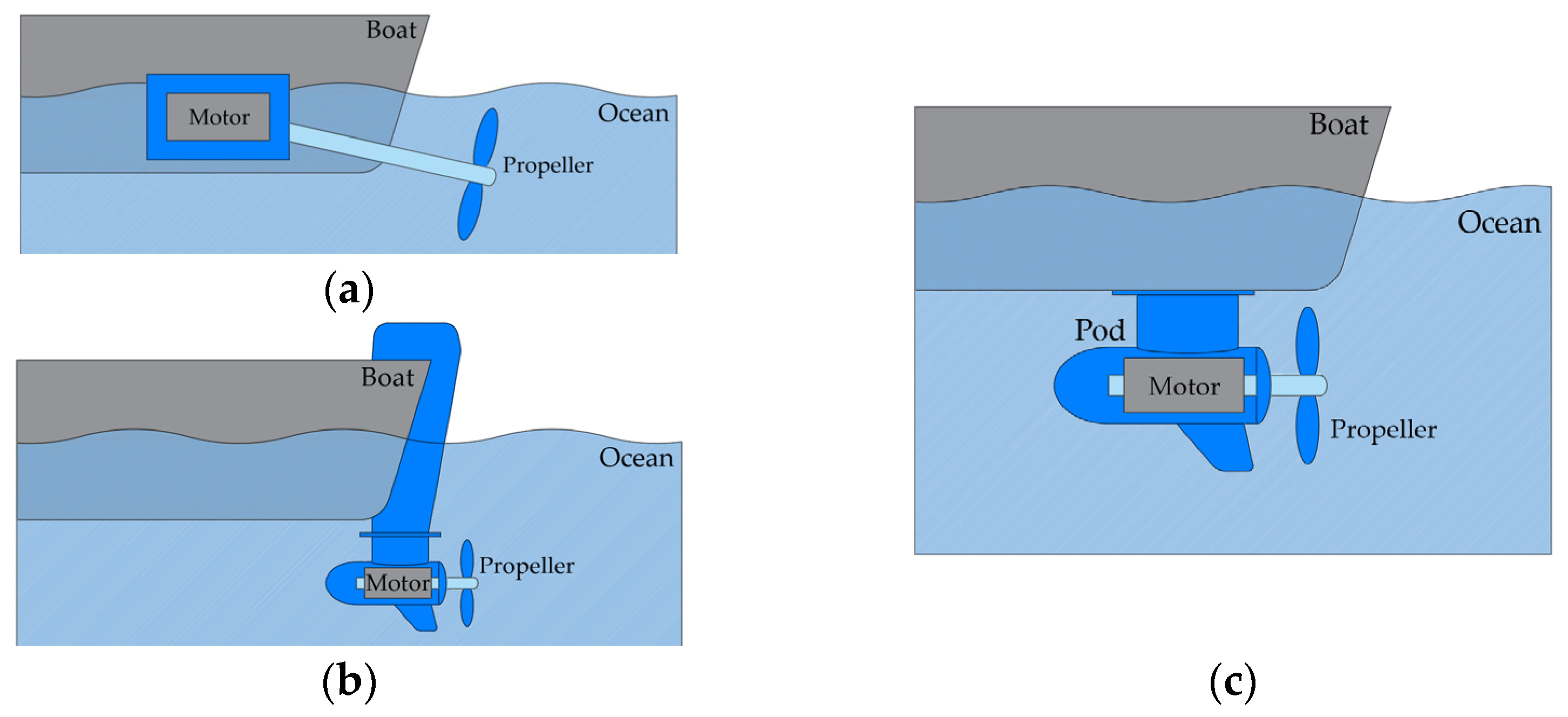
:1. Introduction
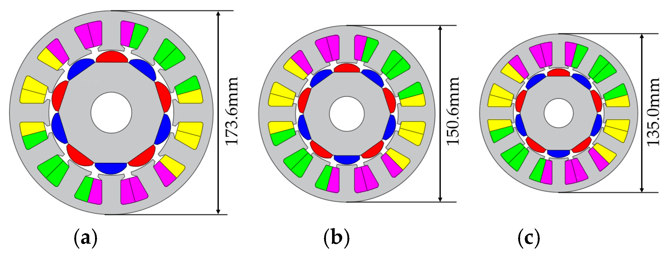
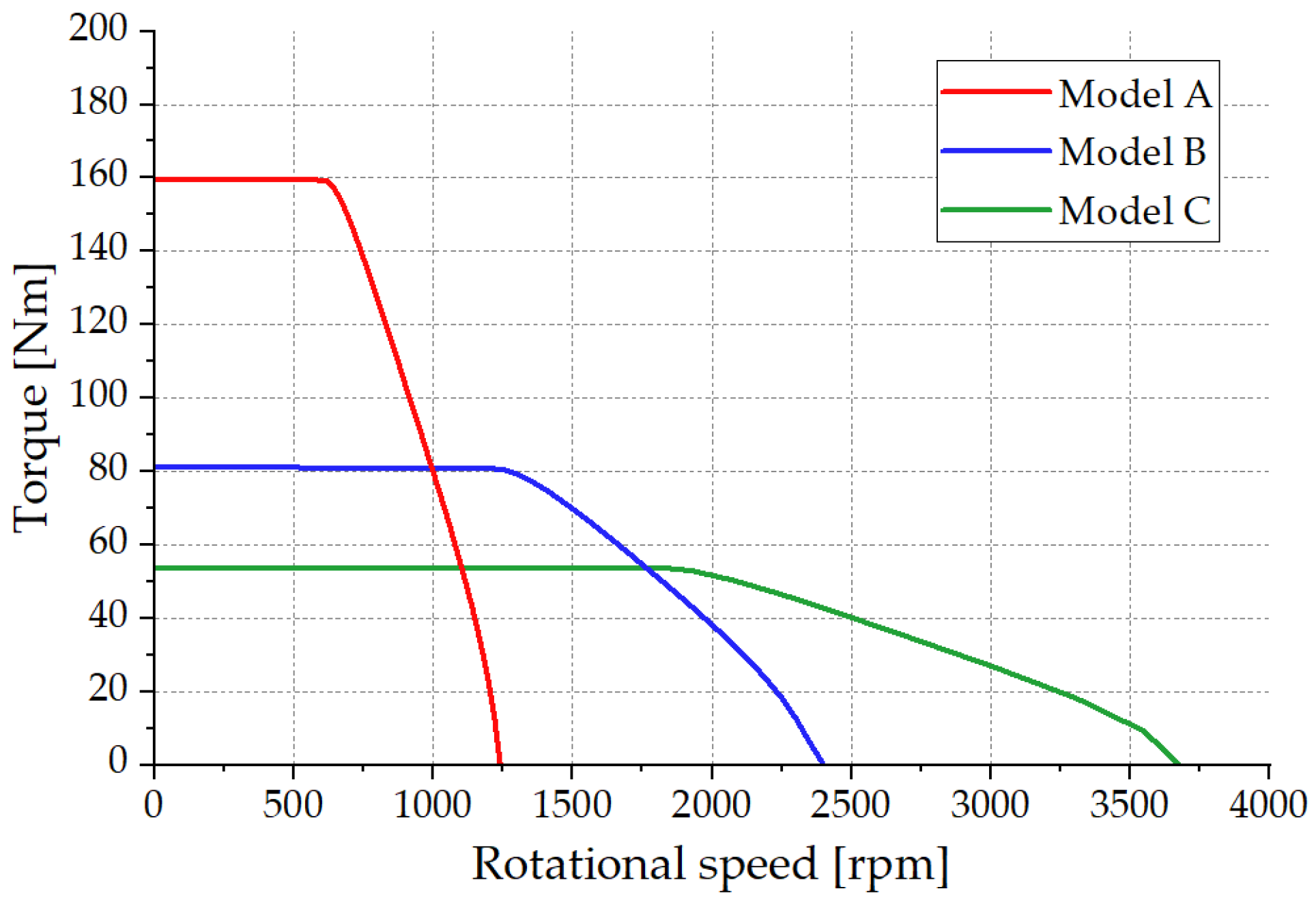
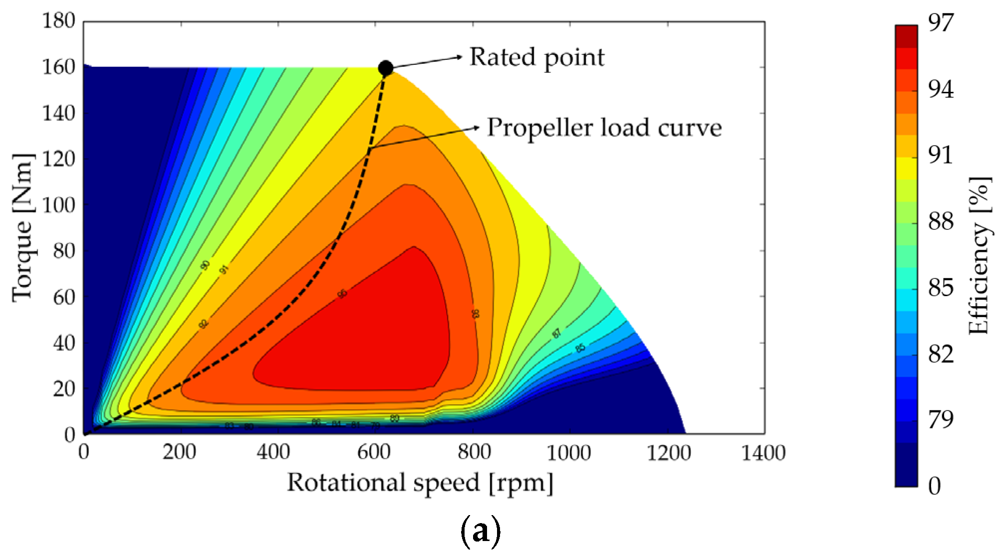
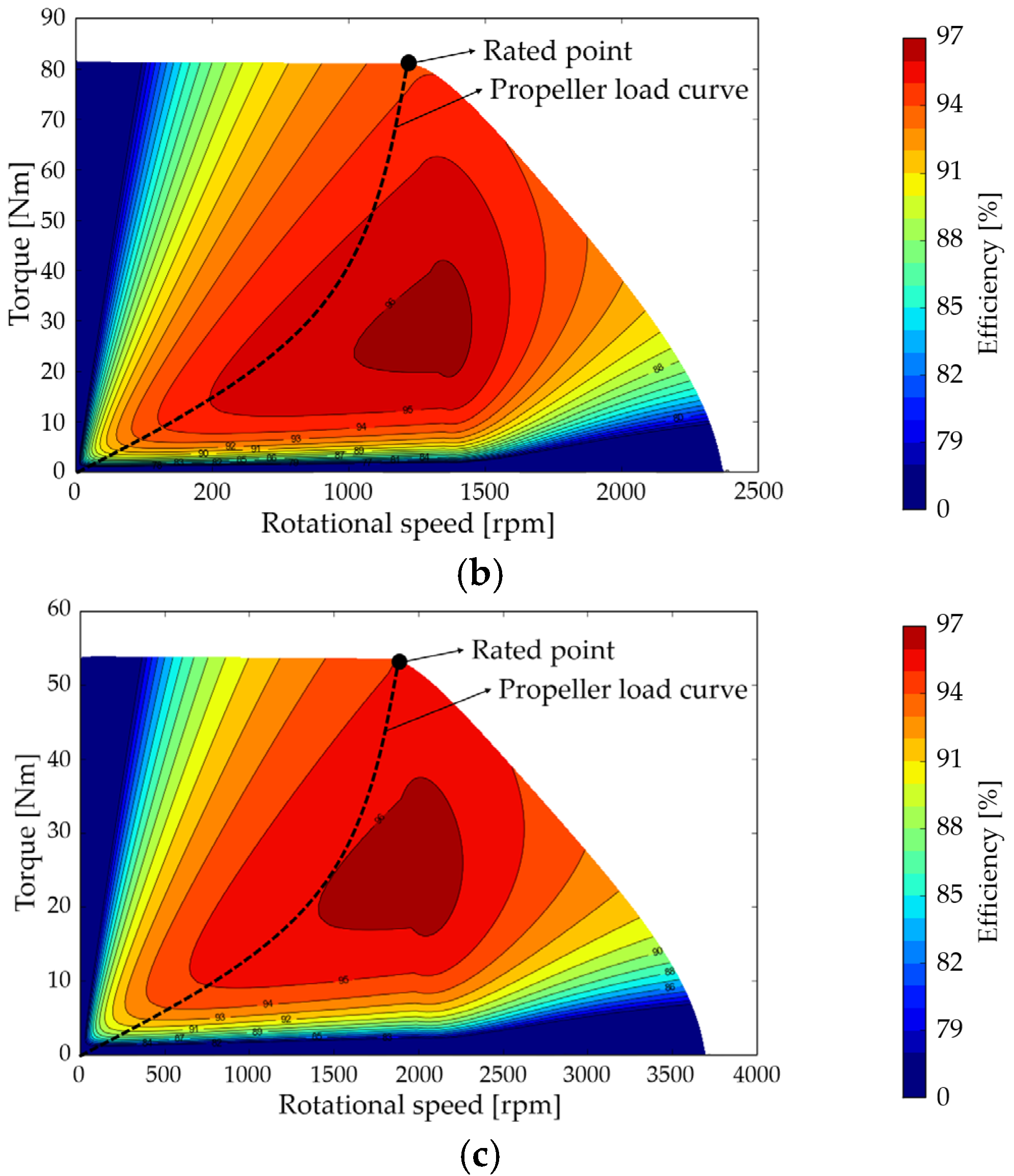
2. Specifications and Design Results of a 10 kW SPMSM for Podded Propulsion
3. Mechanical Analysis of the 10 kW SPMSMs for Podded Propulsion
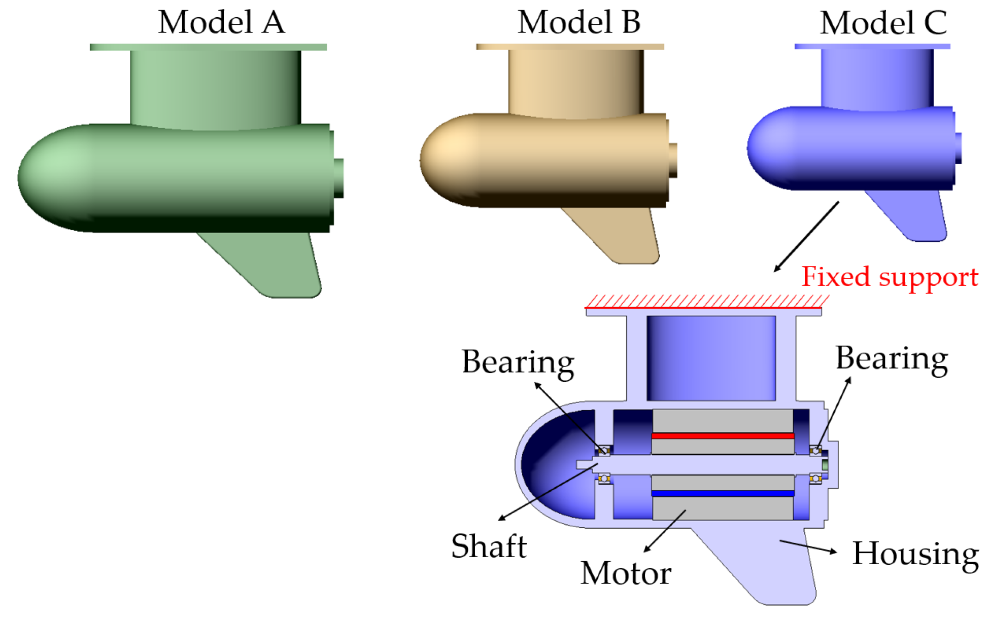
3.1. Podded Propulsor for Mechanical Analysis
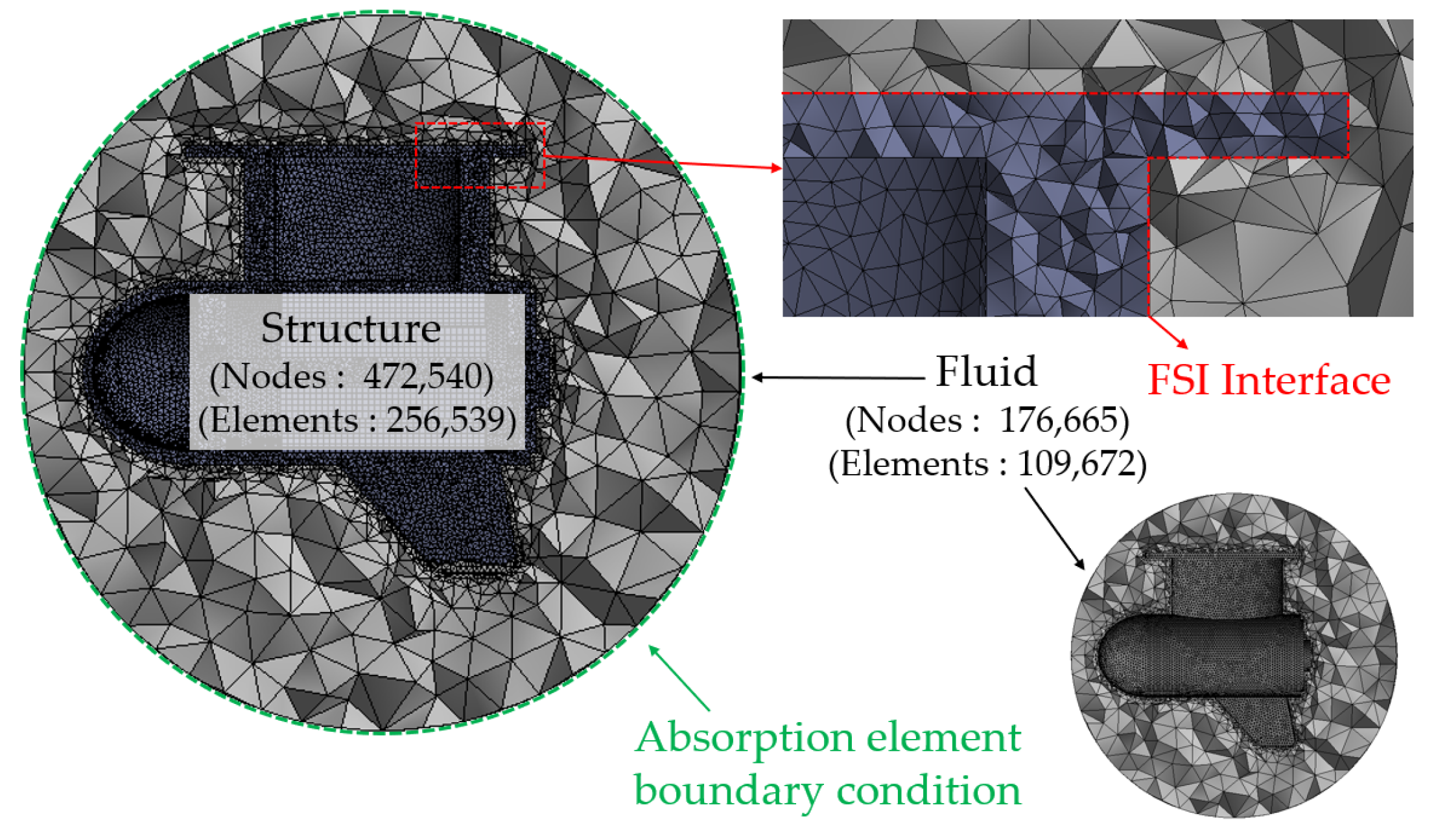
3.2. Modal Acoustic Analysis Considering Fluid-Structure Interaction (FSI)
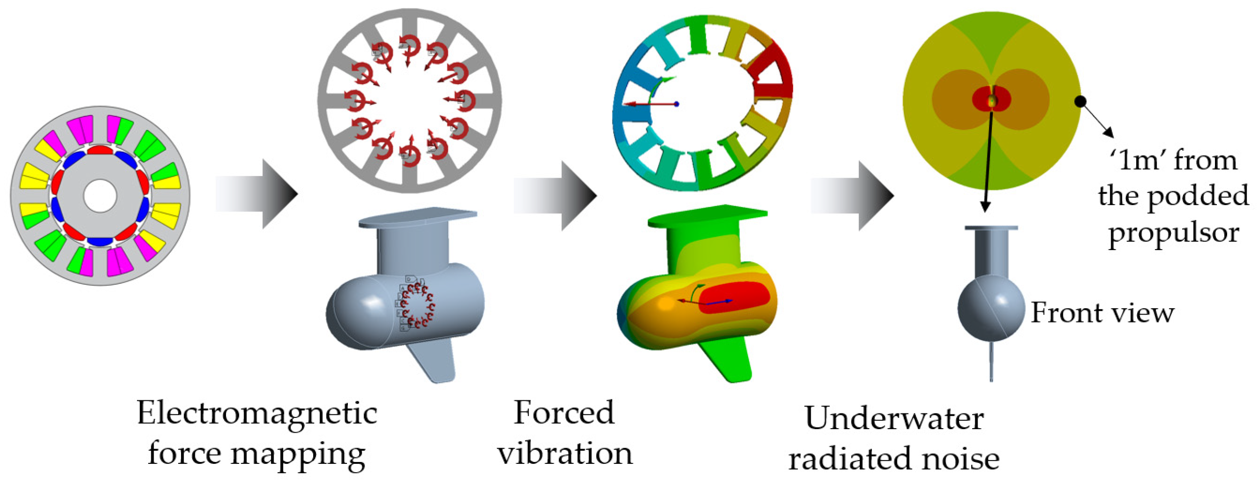
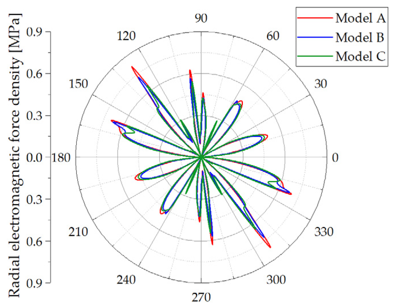
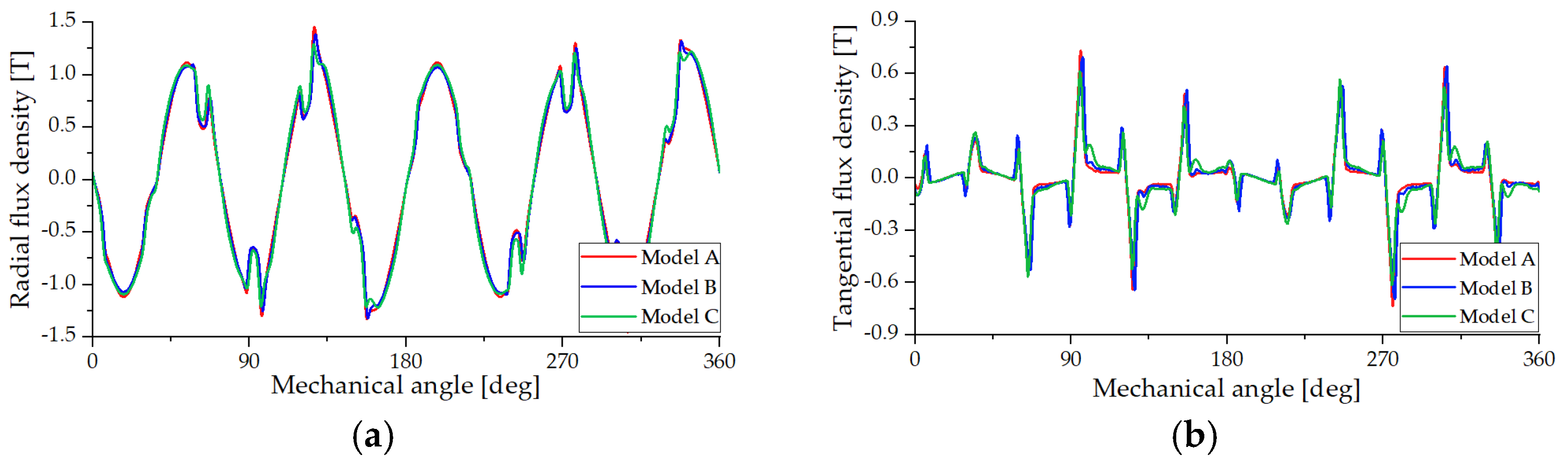
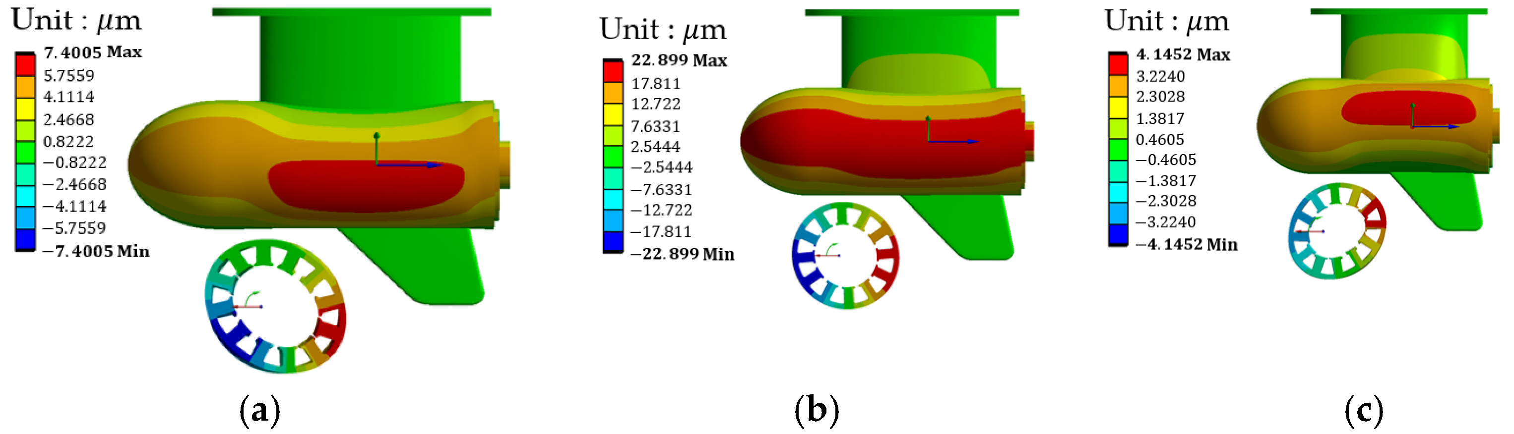
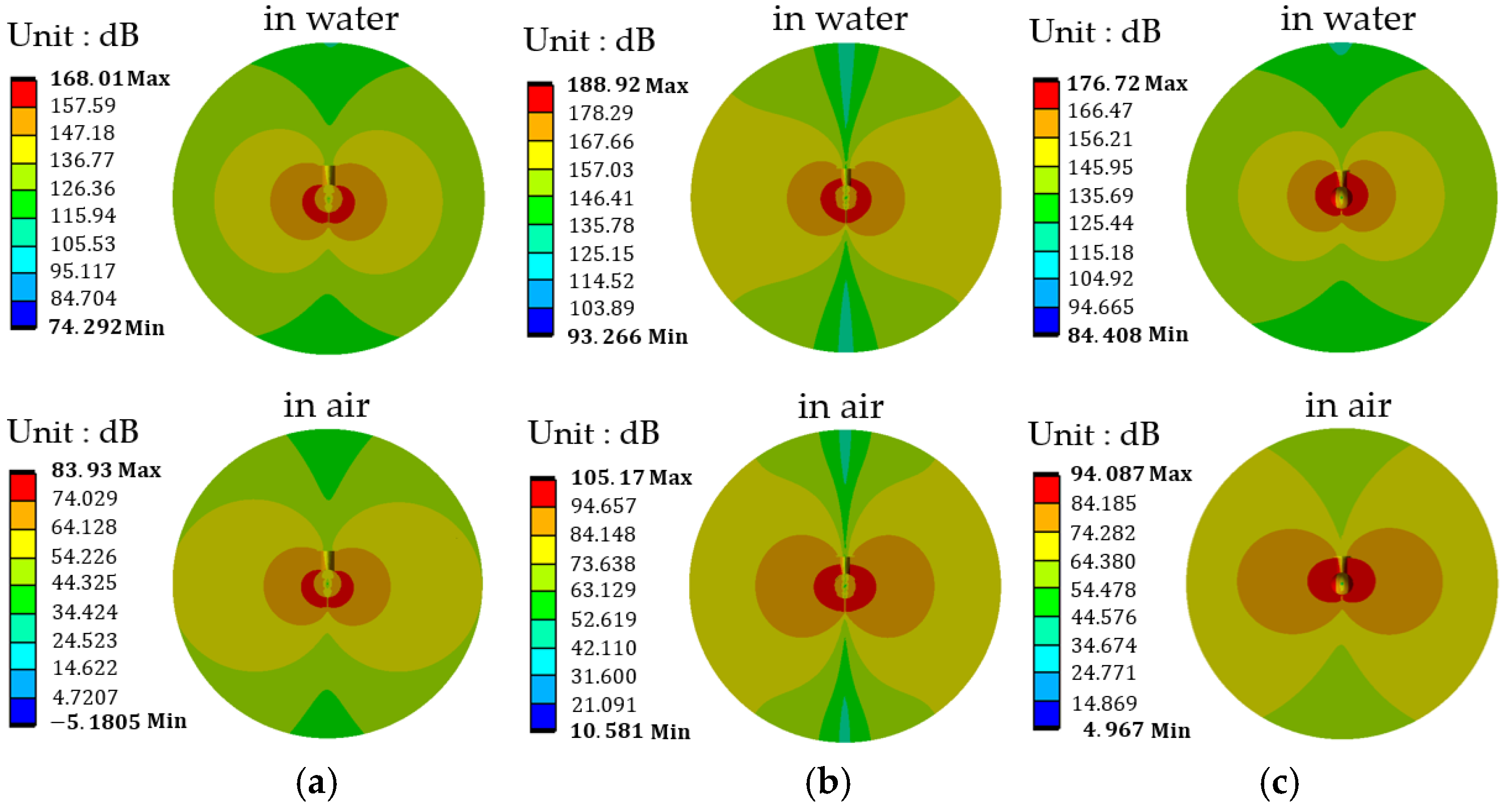
3.3. Forced Vibration and Underwater Radiated Noise Analysis
4. Conclusions
Author Contributions
Funding
Data Availability Statement
Acknowledgments
Conflicts of Interest
References
- Joung, T.H.; Kang, S.G.; Lee, J.K.; Ahn, J. The IMO initial strategy for reducing Greenhouse Gas (GHG) emissions, and its follow-up actions towards 2050. J. Int. Marit. Saf. Environ. Aff. Shipp. 2020, 4, 1–7. [Google Scholar] [CrossRef]
- Litwin, W.; Leśniewski, W.; Piątek, D.; Niklas, K. Experimental Research on the Energy Efficiency of a Parallel Hybrid Drive for an Inland Ship. Energies 2019, 12, 1675. [Google Scholar] [CrossRef]
- Erbe, C.; Marley, S.A.; Schoeman, R.P.; Smith, J.N.; Trigg, L.E.; Embling, C.B. The effects of ship noise on marine mammals—A review. Front. Mar. Sci. 2019, 6, 606. [Google Scholar] [CrossRef]
- Williams, R.; Wright, A.J.; Ashe, E.; Blight, L.K.; Bruintjes, R.; Canessa, R.; Clark, C.W.; Cullis-Suzuki, S.; Dakin, D.T.; Erbe, C.; et al. Impacts of anthropogenic noise on marine life: Publication patterns, new discoveries, and future directions in research and management. Ocean Coast. Man. 2015, 115, 17–24. [Google Scholar] [CrossRef]
- Kirtley, J.L.; Banerjee, A.; Englebretson, S. Motors for Ship Propulsion. Proc. IEEE 2015, 103, 2320–2332. [Google Scholar] [CrossRef]
- Bassham, B.A. An Evaluation of Electric Motors for Ship Propulsion. Ph.D. Thesis, Naval Postgraduate School, Monterey, CA, USA, 2003. [Google Scholar]
- Bianchi, N.; Bolognani, S.; Ruzojcic, B. Design of a 1000 HP Permanent Maget Synchronous Motor for Ship Propulsion. In Proceedings of the 2009 13th European Conference on Power Electronics and Applications, Barcelona, Spain, 8–10 September 2009; pp. 1–8. [Google Scholar]
- Ocak, O.; Aydin, M. A New Hybrid Permanent Magnet Synchronous Motor with Two Different Rotor Sections. IEEE Trans. Magn. 2017, 53, 1–5. [Google Scholar] [CrossRef]
- Hwang, C.C.; Chang, C.M.; Cheng, S.P.; Chan, C.K.; Pan, C.T.; Chang, T.Y. Comparison of Performances between IPM and SPM Motors with Rotor Eccentricity. J. Magn. Magn. Mater. 2004, 282, 360–363. [Google Scholar] [CrossRef]
- Barcaro, M.; Bianchi, N.; Magnussen, F. Analysis and Tests of a Dual Three-Phase 12-Slot 10-Pole Permanent-Magnet Motor. IEEE Trans. Ind. Appl. 2010, 46, 2355–2362. [Google Scholar] [CrossRef]
- Brecher, C.; Schug, R.; Schmitz, S.; Börner, U. Design and Manufacture of a Carbon Fibre Spindle Rotor Project Results “Aerospin—Development of a Highly Precise Spindle Prototype”. Sci. Eng. Compos. Mater. 2007, 14, 219–228. [Google Scholar] [CrossRef]
- Lee, T.-W.; Hong, D.-K. Rotor Design, Analysis and Experimental Validation of a High-Speed Permanent Magnet Synchronous Motor for Electric Turbocharger. IEEE Access 2022, 10, 21955–21969. [Google Scholar] [CrossRef]
- Islam, R.; Husain, I. Analytical Model for Predicting Noise and Vibration in Permanent-Magnet Synchronous Motors. IEEE Trans. Ind. Appl. 2010, 46, 2346–2354. [Google Scholar] [CrossRef]
- Ko, H.-S.; Kim, K.-J. Characterization of Noise and Vibration Sources in Interior Permanent-Magnet Brushless DC Motors. IEEE Trans. Magn. 2004, 40, 3482–3489. [Google Scholar] [CrossRef]
- Esmailian, E.; Ghassemi, H.; Zakerdoost, H. Systematic Probabilistic Design Methodology for Simultaneously Optimizing the Ship Hull–Propeller System. Int. J. Nav. Archit. Ocean Eng. 2017, 9, 246–255. [Google Scholar] [CrossRef]
- Adnanes, A.K. Maritime Electrical Installations and Diesel Electric Propulsion; ABB AS Marine: Oslo, Norway, 2003. [Google Scholar]
- Rodriguez, C.G.; Egusquiza, E.; Escaler, X.; Liang, Q.W.; Avellan, F. Experimental Investigation of Added Mass Effects on a Francis Turbine Runner in Still Water. J. Fluids Struct. 2006, 22, 699–712. [Google Scholar] [CrossRef]
- Huang, X.; Escaler, X. Added Mass Effects on a Francis Turbine Runner with Attached Blade Cavitation. Fluids 2019, 4, 107. [Google Scholar] [CrossRef]
- Hendershot, J.R.; Miller, T.J.E. Design of Brushless Permanent-Magnet Motors; Oxford University Press: London, UK, 1995; pp. 88–90. [Google Scholar]
- Kim, H.-J.; Jeong, J.-S.; Yoon, M.-H.; Moon, J.-W.; Hong, J.-P. Simple Size Determination of Permanent-Magnet Synchronous Machines. IEEE Trans. Ind. Electron. 2017, 64, 7972–7983. [Google Scholar] [CrossRef]
- ANSYS Inc. Mechanical APDL Theory Reference; ANSYS: Canonsburg, PA, USA, 2022. [Google Scholar]
- Zhu, W.; Pekarek, S.; Fahimi, B.; Deken, B.J. Investigation of Force Generation in a Permanent Magnet Synchronous Machine. IEEE Trans. Energy Convers. 2007, 22, 557–565. [Google Scholar] [CrossRef]
- Korea Register. Guidances for Underwater Radiated Noise; Korea Register: Busan, Korea, 2021. [Google Scholar]
- McKenna, M.F.; Ross, D.; Wiggins, S.M.; Hildebrand, J.A. Underwater Radiated Noise from Modern Commercial Ships. J. Acoust. Soc. Am. 2012, 131, 92–103. [Google Scholar] [CrossRef] [PubMed] [Green Version]
- Norton, M.P.; Karczub, D.G. Fundamentals of Noise and Vibration Analysis for Engineers, 2nd ed.; Cambridge University Press: Cambridge, UK, 2003; pp. 273–274. [Google Scholar]


| Description | Model A * | Model B * | Model C * | |
|---|---|---|---|---|
| Rated output power [kW] | 10 | |||
| Rated rotational speed [rpm] | 600 | 1200 | 1800 | |
| Rated torque [Nm] | 159.15 | 79.57 | 53.05 | |
| Supply voltage [Vdc] | 48 | |||
| Current density [Arms/mm2] | 7.6 | |||
| Power factor | 0.93 | |||
| TRV [kNm/m3] | 68 | |||
| Air-gap length [mm] | 0.8 | |||
| Fill-factor [%] | 41 | |||
| Torque ripple [%] | ≤1.0 | |||
| Material | Core | 35PN360 (0.35 mm) | ||
| PM | NdFe–N42UH (1.247 T at 60 °C) | |||
| Winding | Copper–AWG 18 (ϕ 1.08 mm) | |||
| Description | Model A | Model B | Model C | |
|---|---|---|---|---|
| Rated output power [kW] | 10.01 | 10.15 | 10.03 | |
| Rated rotational speed [rpm] | 600 | 1200 | 1800 | |
| Rated torque [Nm] | 159.35 | 80.81 | 53.22 | |
| Current density [Arms/mm2] | 7.66 | 7.59 | 7.63 | |
| Power factor | 0.931 | 0.930 | 0.930 | |
| TRV [kNm/m3] | 68.67 | 68.87 | 68.21 | |
| Torque ripple [%] | 0.90 | 0.54 | 0.94 | |
| SR | 2.57 | 2.42 | 2.26 | |
| Rated current [Arms] | 227 | 225 | 201 | |
| Efficiency [%] | 90.20 | 93.17 | 94.37 | |
| Total loss [%] | 1081.84 | 744.4 | 598.6 | |
| Losses [W] | Copper | 969.5 | 610.3 | 443.3 |
| PM | 9.34 | 14.8 | 12.4 | |
| Iron | 53.0 | 69.3 | 92.9 | |
| Mechanical * | 50 | 50 | 50 | |
| Outer diameter of stator [mm] | 173.6 | 150.6 | 135 | |
| Inner diameter of stator [mm] | 106.6 | 87.6 | 77.6 | |
| Outer diameter of rotor [mm] | 105 | 86 | 76 | |
| Thickness of stator yoke [mm] | 8 | 7.5 | 6.5 | |
| Stack length [mm] | 268 | 202 | 172 | |
| The number of turns per slot | 6 | 5 | 5 | |
| The number of strands per turn | 18 | 18 | 16 | |
| Parallel branch | 2 | 2 | 2 | |
| Resistance per phase [ohm] | 0.006271 | 0.004018 | 0.003657 | |
| Active volume of motor [m3] | 0.00639 | 0.00363 | 0.00246 | |
| Active weight of motor [kg] | 41.40 | 23.43 | 15.85 | |
| Description | Structure | |||
| Housing | Motor | |||
| Core | PM | Shaft | ||
| Material | Aluminum | 35PN360 | N42UH | SUS304 |
| Density [kg/m3] | 2810 | 7600 | 7650 | 8000 |
| Young’s modulus [GPa] | 71.7 | 195 | 153 | 193 |
| Poisson’s ratio | 0.33 | 0.25 | 0.24 | 0.285 |
| Description | Fluid | |||
| Material | Air | Water | ||
| Density [kg/m3] | 1.225 | 998.2 | ||
| Speed of sound [m/s] | 346.2 | 1482.1 | ||
| Description | Model A | Model B | Model C | |
|---|---|---|---|---|
| 1st natural frequency [Hz] (bending mode) | in air | 172.17 | 213.43 | 239.52 |
| in water | 154.98 | 189.18 | 212.58 | |
| 2nd natural frequency [Hz] (bending mode) | in air | 494.06 | 590.71 | 629.18 |
| in water | 475.93 | 558.86 | 601.80 | |
| 3rd natural frequency [Hz] (bending mode) | in air | 925.53 | 1097.40 | 1209.10 |
| in water | 823.67 | 981.53 | 1092.90 | |
| Description | Model A | Model B | Model C | |
|---|---|---|---|---|
| Rated rotational speed [rpm] | 600 | 1200 | 1800 | |
| Electrical frequency, [Hz] | 50 | 100 | 150 | |
| Pole-passing frequency, [Hz] | 100 | 200 | 300 | |
| Max. vibration response displacement [μm] | 7.40 | 22.89 | 4.14 | |
| Max. radiated noise at 1 m [dB] | in air | 54.49 | 78.40 | 70.80 |
| in water (URN) | 132.22 | 159.66 | 140.35 | |
Publisher’s Note: MDPI stays neutral with regard to jurisdictional claims in published maps and institutional affiliations. |
© 2022 by the authors. Licensee MDPI, Basel, Switzerland. This article is an open access article distributed under the terms and conditions of the Creative Commons Attribution (CC BY) license (https://creativecommons.org/licenses/by/4.0/).
Share and Cite
Park, J.-H.; Lee, T.-W.; Jeong, Y.-H.; Hong, D.-K. Novel Multi-Physics Computational Simulation of a 10 kW Permanent Magnet Motor for Podded Propulsion. Energies 2022, 15, 6607. https://doi.org/10.3390/en15186607
Park J-H, Lee T-W, Jeong Y-H, Hong D-K. Novel Multi-Physics Computational Simulation of a 10 kW Permanent Magnet Motor for Podded Propulsion. Energies. 2022; 15(18):6607. https://doi.org/10.3390/en15186607
Chicago/Turabian StylePark, Jang-Hyun, Tae-Woo Lee, Yeon-Ho Jeong, and Do-Kwan Hong. 2022. "Novel Multi-Physics Computational Simulation of a 10 kW Permanent Magnet Motor for Podded Propulsion" Energies 15, no. 18: 6607. https://doi.org/10.3390/en15186607
APA StylePark, J.-H., Lee, T.-W., Jeong, Y.-H., & Hong, D.-K. (2022). Novel Multi-Physics Computational Simulation of a 10 kW Permanent Magnet Motor for Podded Propulsion. Energies, 15(18), 6607. https://doi.org/10.3390/en15186607