Article

Optimal Design of Permanent Magnet Synchronous Machine Based on Random Walk Method and Semi 3D Magnetic Equivalent Circuit Considering Overhang Effect

1
Department of Electrical Engineering, Chungnam National University, Daejeon 34134, Korea
2
R&D Traction Machine Development Team, Hyundai Elevator, Chungju 27329, Korea
3
Advanced Brake System Engineering Cell, Hyundai Mobis, Yongin 16891, Korea
4
Department of Biosystems Machinery Engineering, Chungnam National University, Daejeon 34134, Korea
*
Author to whom correspondence should be addressed.
Energies 2022, 15(21), 7852; https://doi.org/10.3390/en15217852
Submission received: 1 September 2022 / Revised: 18 October 2022 / Accepted: 21 October 2022 / Published: 23 October 2022
(This article belongs to the Special Issue Regulations and Advances in High Performance Electric Motor and Drive)

Abstract

:
Permanent magnet synchronous machines (PMSMs) with an overhang structure can increase power density by compensating for the increased magnetic energy of permanent magnets. To analyze the overhang structure, a three-dimensional (3D) analysis of PMSMs is essential. However, 3D analysis takes a long time and the modeling process is complicated in the initial design stage. To overcome these problems, a magnetic equivalent circuit technique is applied to the 2D model. In this paper, an optimal design method for PMSMs with an overhang structure is proposed based on the semi 3D magnetic equivalent circuit (MEC) and random walk method. By using semi 3D MEC, it is possible to quickly analyze PMSM and obtain accurate electromagnetic analysis results considering the overhang effect. Moreover, the volume and weight of PMSM can be minimized by optimizing the rotor’s four design parameters using a random walk algorithm. To obtain high efficiency, the objective function is selected so that copper loss is minimized under the same constraints. The validity of the proposed design technique is verified by comparing the analysis results of semi 3D MEC and 3D finite element method for the derived optimal model.

1. Introduction

Permanent magnet synchronous motors (PMSMs) with high energy density can improve system performance with high efficiency and high power density. To compensate for leakage flux such as the fringing effect and achieve high power density, an overhang design technique in which the rotor is designed to be relatively thicker than the thickness of the stator that is applied to PMSM. The three-dimensional (3D) finite element method (FEM) is essential to analyze the overhang structure. The 3D FEM has reliable analysis results but requires a lot of analysis time. Therefore, in the initial design and optimal design of PMSM with numerous design variables, analysis using FEM is time-consuming and insufficient to obtain insight between design variables and performance.
To efficiently design PMSM to solve these problems, it is necessary to study accurate and fast analysis techniques. Various studies on the electromagnetic analysis of PMSM with an overhang structure have been conducted [1,2,3].
Two methods are mainly applied to the electromagnetic analysis of the overhang structure: 3D FEM and magnetic equivalent circuit (MEC). Although the MEC is less accurate than the 3D FEM, it can obtain numerous results over a short period through fast analysis. With these advantages, electromagnetic analysis can be quickly performed in the initial design process.
In this paper, based on the proposed analysis method, the optimal design of PMSM using semi 3D MEC and random walk algorithms (RWA’s) was performed. Using the semi 3D MEC, the analysis time of electromagnetic characteristics considering the overhang structure was reduced. The validity of the semi 3D MEC method was verified by comparing analysis results with those of the 3D FEM.
Furthermore, an optimal design for improving the power density of PMSM by applying RWA was achieved. The optimal design proposed in this paper minimizes the weight and volume while maintaining the same electromagnetic performance.

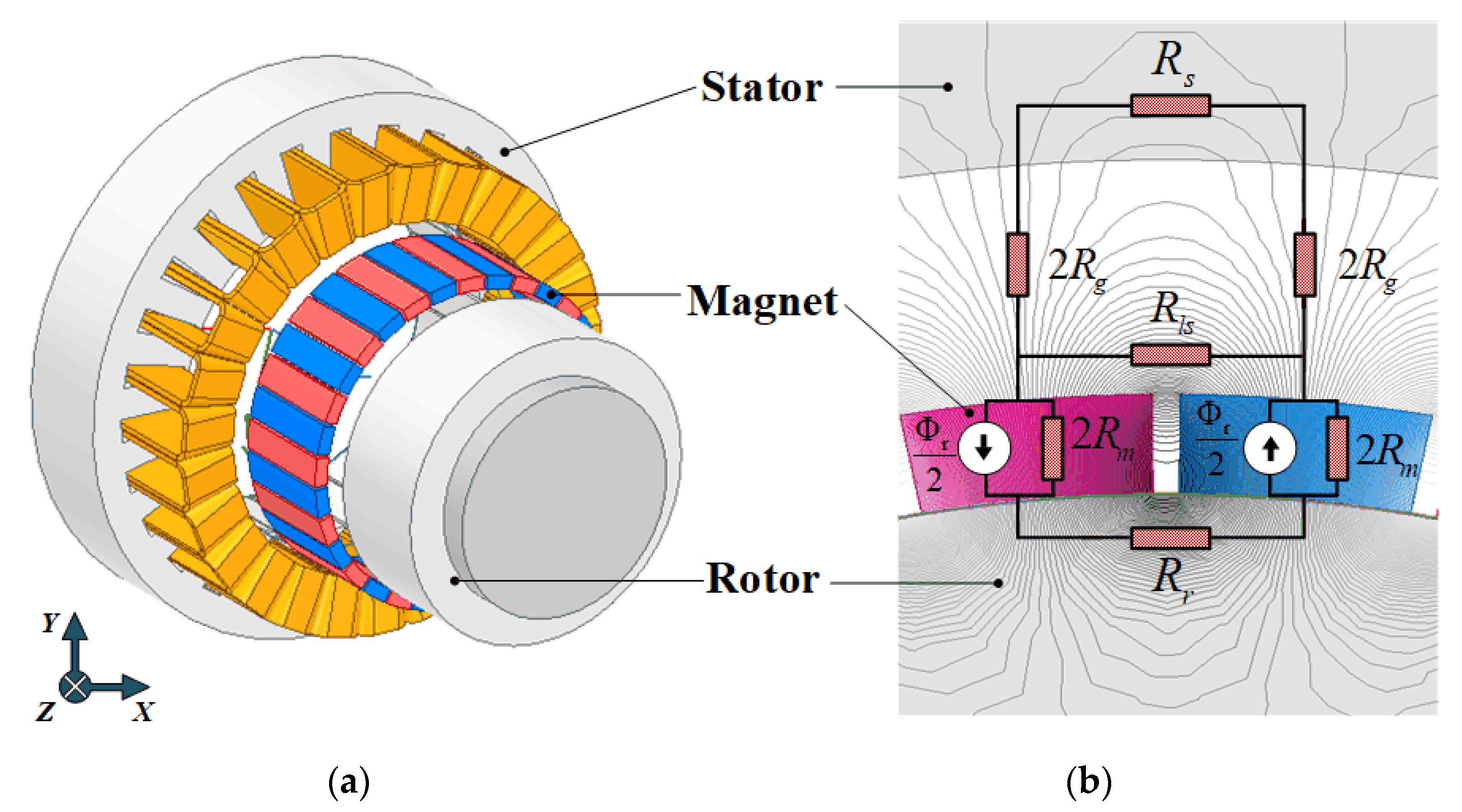
2. Magnetic Equivalent Circuit Model of PMSM

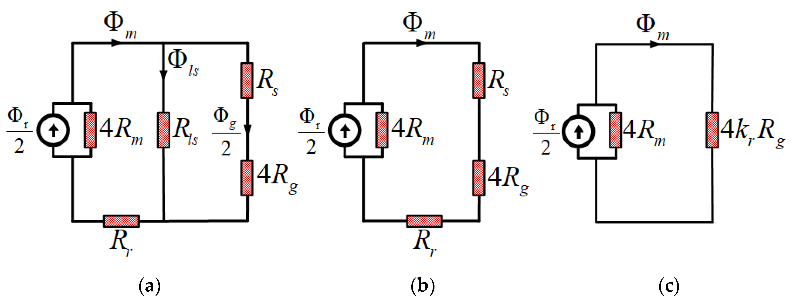
2.1. Simplification of MEC

The initial model for the optimization design and MEC are shown in Figure 1a,b. As shown in Figure 2b, the electromagnetic analysis was performed using the slotless model. In the MEC shown in the same figure, Rg, Rm, Rs, Rr, Rls, and Φr are the air gap reluctance, reluctance by the permanent magnet, reluctance of rotor, stator yoke, leakage flux of permanent magnet, and flux of permanent magnet, respectively. Equations (1) and (2) are used to calculate Rg and Rm, respectively. Moreover, g′, μ0, Ag, Tm, and μr denote the effective air gap length, the permeability of vacuum, the axial cross-sectional area of the air gap, the thickness of the permanent magnet, and relative permeability, respectively.
The process of simplifying the MEC of the slotless model is shown in Figure 2. In Figure 1b, the air gap reluctance is simplified through the sum of the series circuit. The result is Figure 2a. In Figure 2a, the magnetoresistance between two permanent magnets can predict the leakage coefficient through the proportional expression of magnetic flux. Therefore, the MEC can be simplified as shown in Figure 2b. Furthermore, Figure 2c shows the simplified MEC with the reluctance coefficient of the iron core applied. kr means the reluctance coefficient of the iron core [4].
R g = g μ A g
R m = T m μ 0 μ r A g
4 R g + R s + R r = 4 k r R g

2.2. Slotting Effect Using Carter’s Coefficient

In this study, the Carter coefficient kc is used to consider the slot effect of the slotless model. The Carter coefficient can be calculated by substituting γ and τt in Equation (6). In Equation (4), γ is obtained by substituting the Bs0 with the width of the slot opening. g′ denotes the air gap length of the slotless model [5]. In Equation (5), Dsi and Ns are the inner radius and number of slots of the stator, respectively. τt can be calculated. In Equation (7), the effective air gap length can be obtained using the Carter coefficient. Therefore, the slot effect can be analyzed in the slotless model [6].
γ = 4 π ( B s 0 2 g tan 1 ( B s 0 2 g ) ln 1 + ( B s 0 2 g ) 2 )
τ t = 2 π D s i / N s
k c = τ t / ( τ t γ g )
g e f f = k c g
The list in Table 1 compares the air gap magnetic flux density of MEC (to which the Carter coefficient is applied) and FEM analysis results. The error rates of maximum values were confirmed to be approximately 1% and 1.6%. The analysis result of the magnetic flux density applying the Carter coefficient to the slotless model has similar results to the analysis result of the model with the slotted stator.

2.3. D MEC Considering Overhang Structure

Figure 3a compensates for the magnetic energy by converting the operating point of the permanent magnet. Figure 3b shows the structure of the permanent magnet overhang. The permanent magnet overhang structure is used to increase the power density of the PMSM. As the overhang increases, the operating point must be converted to compensate for the magnetic energy.
In this study, the overhang length was set to 5 mm, which does not significantly affect the shape of the motor. The left side of Equation (8) is the magnetic energy of the 3D overhang, and the right side is the magnetic energy of the two-dimensional (2D) permanent magnet. In the equation, Bm_3D, Hm_3D, and V_3D mean the magnetic flux density, magnetic field strength, and permanent magnet volume of the 3D overhang. Bm_2D, Hm_2D, and V_2D represent the magnetic flux density, magnetic field strength, and permanent magnet volume of the two-dimensional (2D) permanent magnet. In Equation (9), PC represents the permeance coefficient. To compensate for the magnetic energy according to the overhang structure, the magnetic flux density and magnetic field strength of the 2D permanent magnet are increased. With the former, a 3D permanent magnet with an overhang can be made equivalent to a 2D permanent magnet, as shown in Equation (10) [7,8].
1 2 B m _ 3 D H m _ 3 D V 3 D = 1 2 B m _ 2 D H m _ 2 D V 2 D
B m _ 2 D = μ 0 P C ( V 3 D V 2 D ) B m _ 3 D H m _ 3 D , H m _ 2 D = B m _ 2 D ( μ 0 P C )
B r _ 2 D = B m _ 2 D μ r μ 0 H m _ 2 D
Table 2 summarizes the conversion results of the operating point of the permanent magnet. The left and right sides of the table list the operating points of the 3D permanent magnet with overhang and the 2D equivalent permanent magnet, respectively [9,10].

2.4. Electromagnetic Analysis Based on MEC

The semi 3D MEC is an electromagnetic analysis using the air gap magnetic field characteristics of PMSM with overhang. Using the reluctance and remanence magnetic flux density obtained from Equations (1)–(3) and (10), the air gap flux density of PMSM with overhang can be calculated. In Equations (11) and (12), ϕr and ϕm are the remanence magnetic flux of the permanent magnet with overhang and the amount of half-pole magnetic flux, respectively. The axial cross-sectional area of the permanent magnet with overhang is denoted by Am. In Equation (12), kr is the reluctance coefficient. In Equation (13), ϕg and kls represent the air-gap flux per pole of the permanent magnet with overhang and the leakage coefficient between two poles, respectively. Moreover, by doubling the magnetic flux magnitude of the overhang half-pole in Equation (13), the magnetic flux magnitude of ϕg can be regarded as the air-gap flux per pole [11].
ϕ r = B r _ 2 D A m
ϕ m = ϕ r / 2 1 + k r ( R g / R m )
ϕ g = k l s 2 ϕ m
By substituting ϕg obtained in Equation (13) into the identity equation of the magnetic flux density, the air gap magnetic flux density Bg of the overhang can be derived using Equation (14).
B g = ϕ g / A g
To derive the maximum value of flux linkage in one phase, the position of the permanent magnet must coincide with the teeth of the stator. For this reason, the integral range in Equation (15) is selected as the coil pitch angle of one phase; ϴcoil_pitch denotes the coil pitch. In Equation (15), Nph is the number of equivalent series turns; L is the stack; q is the number of pole pairs; Bn is the air-gap flux density of the nth harmonic; ωm is the mechanical angular velocity; and t is the period.
According to Equation (16), the back electromotive force (back EMF) can be calculated as the amount of change in flux linkage according to the period [12].
λ P h = ( N p h D s i q L ) B n θ C o i l _ p i t c h _ e n d θ C o i l _ p i t c h _ s t a r t cos ( q ( θ ω m t ) )
E P h = N p h d ϕ d t
The analysis results of semi 3D MEC and FEM about the back EMF and flux linkage waveforms of PMSM with overhang are compared in Figure 4a,b. The back EMF and flux linkage waveform waveforms according to revolutions per minute (RPM) are shown in Figure 4a,b. The error rate was confirmed to be approximately 6%.

3. Optimal Design of PMSM Using RWA

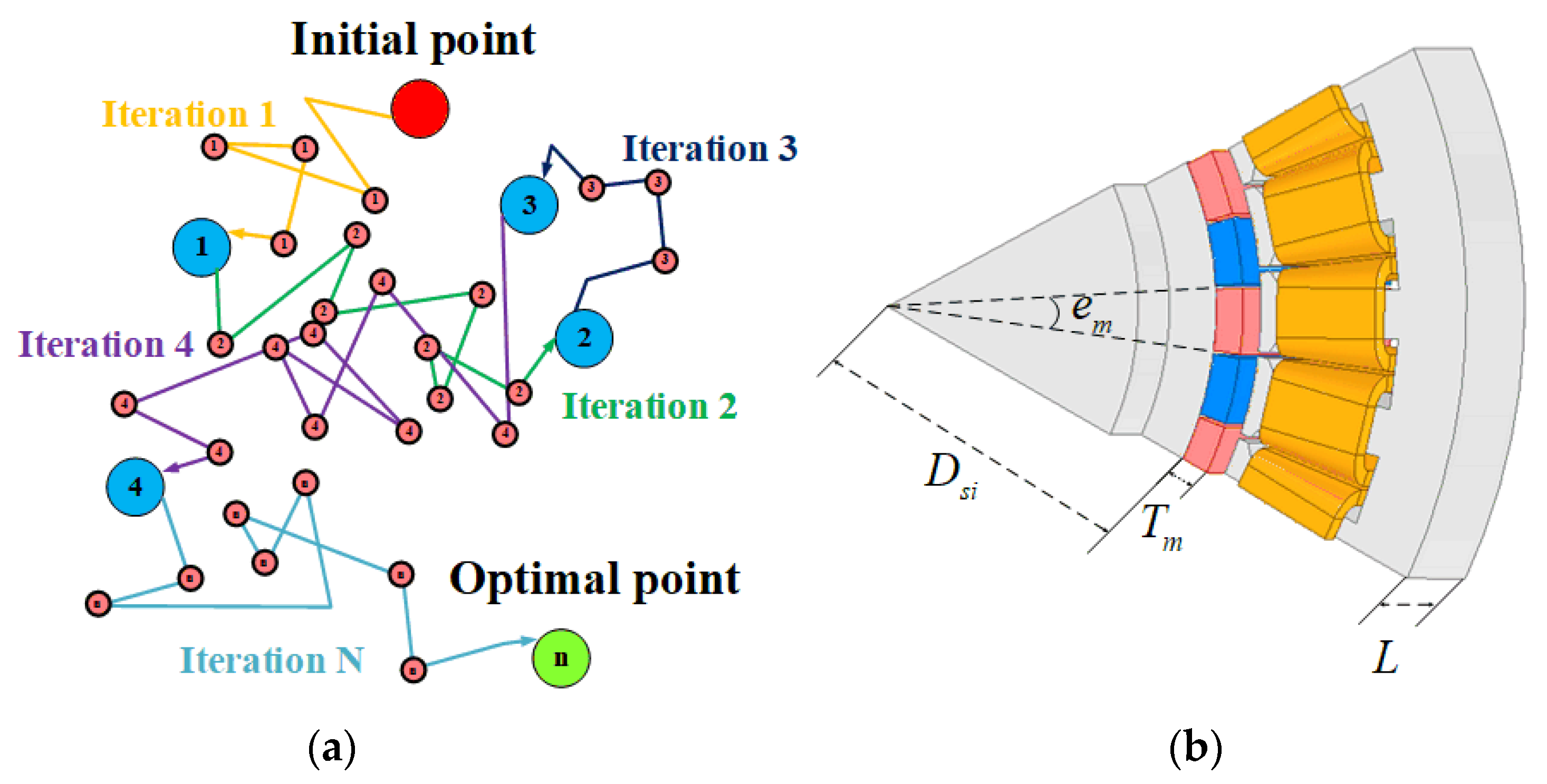
3.1. Random Walk Algorithm’s Method

Figure 5a shows the iteration process of RWA. The RWA is a technique for finding the minimum value of a nonlinear function, using a random number. The mechanism of RWA for finding the minimum value is as Equation (17); it proceeds as follows. Move object variable Zn to Zn+1 by the size of the Walk in the direction of the random number. Substitute Zn+1 into the Object function, and repeat the previous step using the current value if it is less than the previous value. After repeating these steps n times, the search range of the Walk is reduced by a certain percentage. Eventually, the global minimum will be reached. Furthermore, if it exceeds the set number of repetitions n, the RWA is terminated, and the current minimum value is considered as the minimum value of the Object function.
Z n + 1 = Z n + R a n d o m W a l k
  • Zn: variable value
  • Walk: search range
  • Radom: A random number between −1 and 1

3.2. Optimal Design Application of PMSM

In this study, a concentrated winding type PMSM is used. The methods for minimizing the weight and volume of PMSM include magnetic field separation, electric field separation, and D and L separation. However, using all of them is difficult.
Therefore, for the optimal design of PMSM, a method for designing the shape of the stator using a magnetic field according to the shape of the rotor was applied. The rotor design parameters used in the optimal design are shown in Figure 5b, where Dsi, em, Tm, and L denote the rotor outer diameter, pole arc ratio, permanent magnet thickness, and stack length, respectively [13].
An optimal design flowchart applying RWA and semi 3D MEC is shown in Figure 6. First, the phase voltage limit value is obtained using Equation (18) with the input voltage based on the design specification. In this equation, Vdc and ie are the input voltage and inverter efficiency, respectively.
The space vector pulse width modulation (SVPWM) was used as the modulation method of the voltage supplied from the inverter. Moreover, the phase voltage satisfies the voltage equation when operating at a value less than 85% of the input voltage. A phase voltage limit of 85% was selected for this study [14].
E l i m i t = V d c 3 i e 0.85 %
Using the magnetic flux density of the 2D equivalent model presented in the previous section, the maximum value of magnetic flux per pole and flux linkage can be calculated. The number of turns not exceeding the phase voltage limit can be calculated according to Equation (19). By calculating the phase current Arms value using the number of turns obtained by Equation (19), the area per conductor and copper loss can be derived according to Equations (20) and (21), respectively.
t u r n = E l i m i t F p e a k W e
If the area per conductor can be obtained, the required slot area can be derived. In Equation (20), Cz, Cslot_area, j, Rph, and Layer denote the area per conductor, slot area, maximum current density, phase resistance, and number of layers, respectively. The layer value of PMSM using concentrated winding is 2 [15].
C z = A r m s j , C s l o t _ a r e a = L a y e r t u r n C z
C o p p e r L o s s = 3 A r m s 2 R p h
To calculate the shape of the stator, the tooth width tw can be obtained according to the tooth saturation limit value Btm of the stator in Equation (22). In general, the saturation limit of electrical steel is 1.6~1.7 T. Considering the armature reaction, the saturation limit of the stator teeth was selected as 1.5 T. In Equation (22), Fgap, Nsm, L, and lf represent the air gap flux of one pole, number of slots per pole, stack length, and fill factor.
The rotor and stator core saturation limits are defined as a ratio formula to the stator tooth saturation limits. By substituting the ratio formula for the saturation of the stator teeth into Equations (23) and (24), the thickness of the stator teeth and the length of the rotor and stator core can be calculated. tstw is the thickness of the stator teeth, and tsc, trc are the lengths of the rotor and stator core [16].
t s t w = F g a p N s m B t m L l f
t s c = 1 2 B t m B s c t w N s m
t r c = 1 2 B t m B r c t w N s m

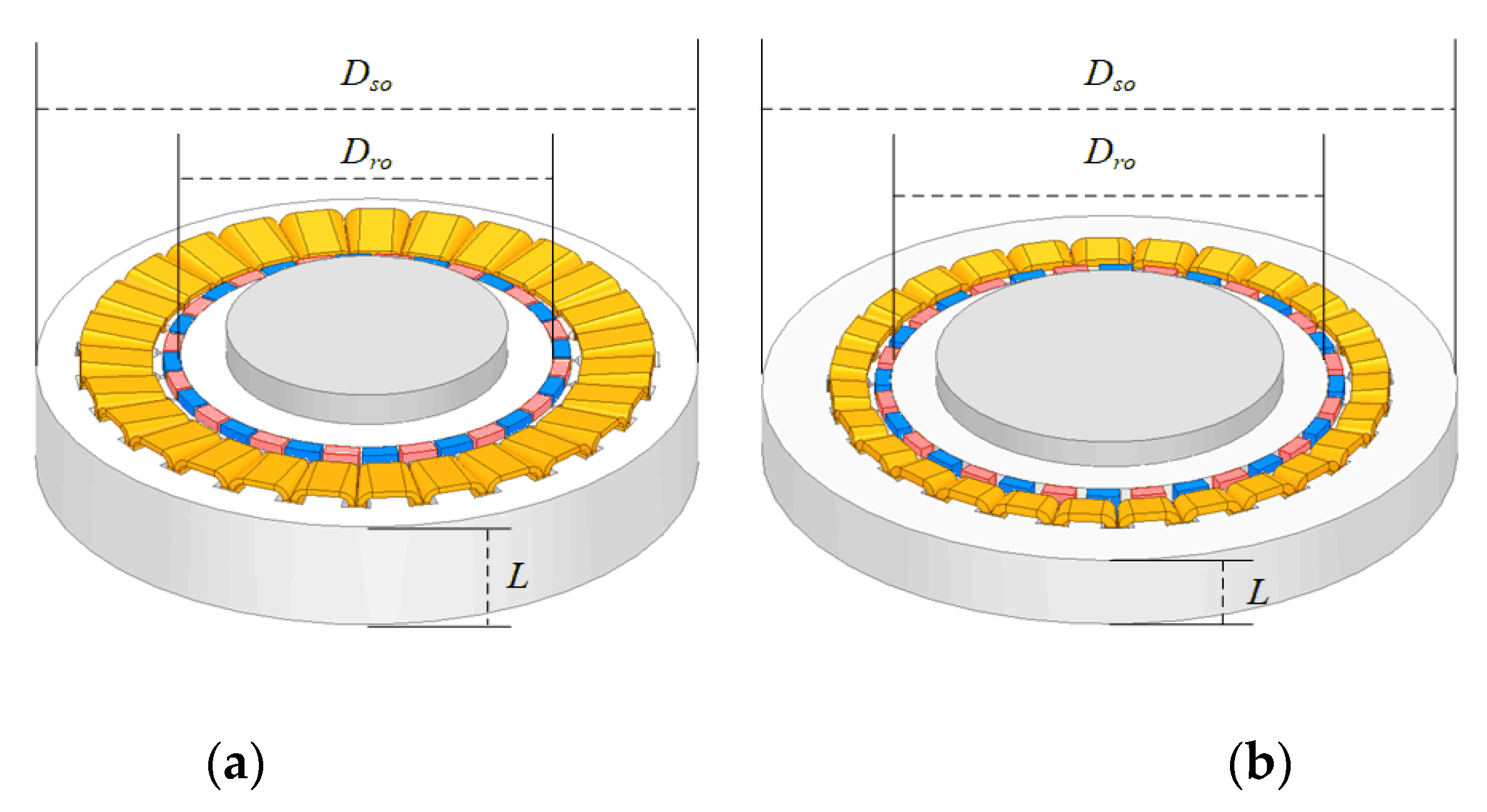
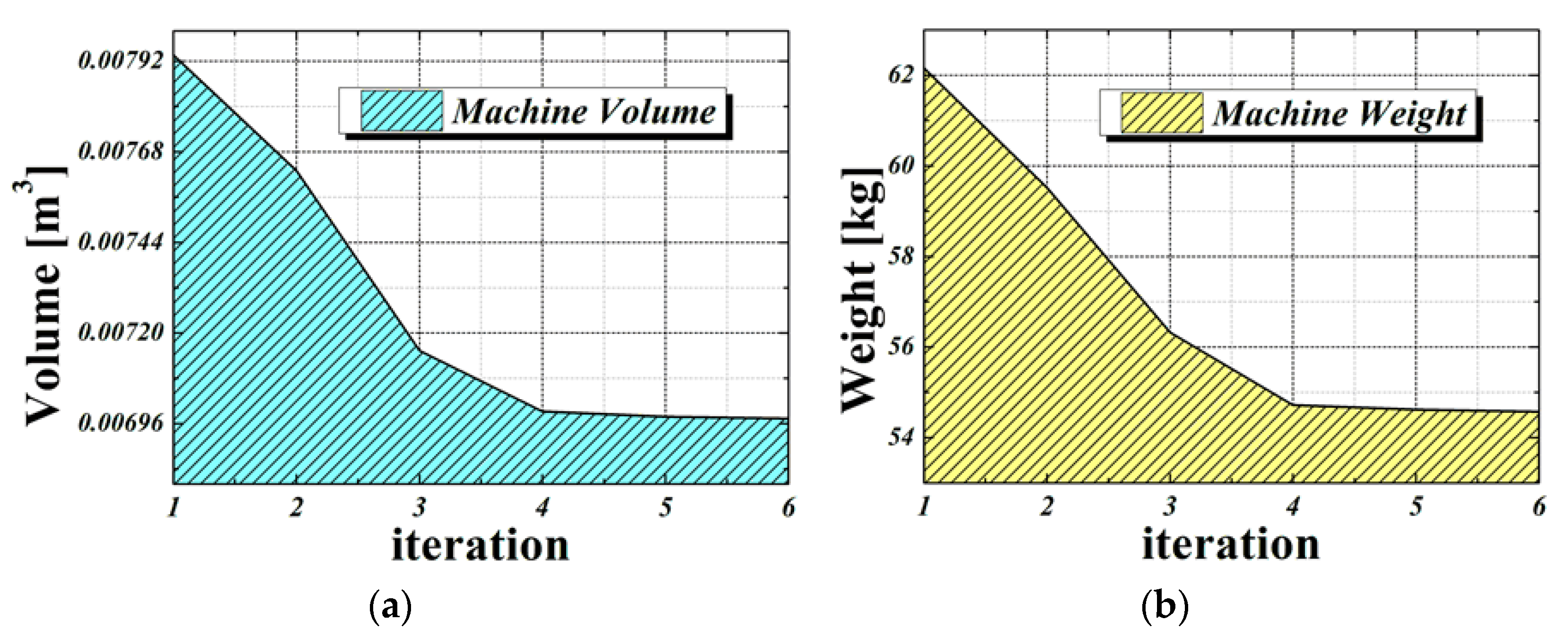
3.3. PMSM Optimal Design Results

Table 3 summarizes the design specifications of the initial and optimal models. The shapes of the initial and optimal models are shown in Figure 7a,b. Six successful results from approximately 4000 optimal design iterations in the initial model are shown Figure 8. The volume and weight are reduced to approximately 900 mm3 and 7.56 kg, as shown in Figure 8a,b.
In the list in Table 3, the optimal model shows that despite the volume and weight reductions, the efficiency is maintained at 93%. Furthermore, Table 4 compares the analysis time and CPU utilization between commercial software and the proposed design method. The finite element method-based commercial software consumes more than 80% utilization at a CPU clock of 3.7 Ghz, and the analysis time takes about 133 h. On the other hand, the proposed optimal design method consumes about 45 to 60% utilization at a CPU clock of 3.7 Ghz, and the analysis time takes about 10 h. This shows that CPU utilization and analysis time are reduced very efficiently [17,18].

4. Conclusions

In this study, an optimal design method using semi 3D MEC and RWS was presented to improve the power density of SPMSM with an overhang structure. Using semi 3D MEC, analysis results of 3D models with overhang structures were obtained quickly and accurately. To secure the validity of the proposed semi 3D MEC, the FEM analysis results of the 3D model with overhang structure are compared with the analysis results of semi 3D MEC. The analysis results showed good agreement.
In addition, the optimal design was performed by setting the objective function for power density improvement using RWA. Through this, the power density was improved by reducing the volume by about 11.39% and the weight by about 12.16% in the same efficiency performance. Therefore, the analysis method and optimal design process proposed in this study can be widely used through rapid analysis and design in the initial and optimal design. In particular, it can be useful for an optimal design that requires a lot.

Author Contributions

Funding acquisition, D.-H.L.; Methodology, W.-H.K.; Supervision, J.-Y.C.; Writing—original draft, S.-m.K. and W.-S.J.; Writing—review & editing, W.-H.K., T.-K.B., D.-H.L. and Y.-J.K. All authors have read and agreed to the published version of the manuscript.

Funding

This research was supported by the Korea Institute of Planning and Evaluation for Technology in Food, Agriculture, and Forestry (IPET) through the Advanced Production Technology Development Program Ministry of Agricultural, Food and Rural Affairs (MAFRA) (Project No. 321061−2); This work was supported by the National Research Foundation of Korea (NRF) grant funded by the Korea government (MSIT) (Project No. 2020R1A2C1007353).

Data Availability Statement

Not applicable.

Conflicts of Interest

The authors declare no conflict of interest.

References

  1. Woo, D.-K.; Lim, D.-K.; Yeo, H.-K.; Ro, J.-S.; Jung, H.-K. A 2-D Finite-Element Analysis for a Permanent Magnet Synchronous Motor Taking an Overhang Effect into Consideration. IEEE Trans. Magn. 2013, 49, 4894–4899. [Google Scholar] [CrossRef]
  2. Kim, K.-C.; Koo, D.-H.; Lee, J. The Study on the Overhang Coefficient for Permanent Magnet Machine by Experimental Design Method. IEEE Trans. Magn 2007, 43, 2483–2485. [Google Scholar] [CrossRef]
  3. Hendershot, J.R., Jr.; Miller, J.R.E. Design of Brushless Permanent-Magnet Motors; MagnaPhysics: Hillsboro, OH, USA; Oxford, UK, 1994; pp. 150–160. [Google Scholar]
  4. Yeo, H.-K.; Lim, D.-K.; Woo, D.-K.; Ro, J.-S.; Jung, H.-K. Magnetic Equivalent Circuit Model Considering Overhang Structure of a Surface-Mounted Permanent-Magnet Motor. IEEE Trans. Magn. 2015, 51, 1–4. [Google Scholar]
  5. Boldea, I.; Nasar, S.A. The Induction Machine Handbook; CRC express: Boca Raton, FL, USA, 2001; pp. 143–150. [Google Scholar]
  6. Hanselman, D.C. Brushless Permanent Magnet Motor Design; MagnaPhysics: Hillsboro, OR, USA; Oxford, MS, USA, 2003; pp. 16–38. [Google Scholar]
  7. Yeo, H.-K.; Ro, J.-S. Novel Analytical Method for Overhang Effects in Surface-Mounted Permanent-Magnet Machines. IEEE Trans. Magn. 2019, 7, 148453–148461. [Google Scholar] [CrossRef]
  8. Pluk, K.J.W.; Jansen, J.W.; Lomonova, E.A. 3-D Hybrid Analytical Modeling: 3-D Fourier Modeling Combined with Mesh-Based 3-D Magnetic Equivalent Circuits. IEEE Trans. Magn. 2015, 51, 11–13. [Google Scholar]
  9. Song, J.-Y.; Lee, J.H.; Kim, Y.-J.; Jung, S.-Y. Computational Method of Effective Remanence Flux Density to Consider PM Overhang Effect for Spoke-Type PM Motor With 2-D Analysis Using Magnetic Energy. IEEE Trans. Magn. 2016, 52, 2–4. [Google Scholar] [CrossRef]
  10. Shin, H.-S.; Shin, K.-H.; Jang, G.-H.; Cho, S.-K.; Jung, K.-H.; Choi, J.-Y. Experimental Verification and 2D Equivalent Analysis Techniques of BLDC Motor with Permanent Magnet Overhang and Housing-Integrated Rotor Core. IEEE TAS 2020, 30, 2–3. [Google Scholar] [CrossRef]
  11. Busch, T.J.; Lax, J.D.; Lipo, T.A. Magnetic circuit modeling of the field regulated reluctance machine Part II: Saturation modeling and results. IEEE Trans. Energy Convers 1996, 11, 57–59. [Google Scholar] [CrossRef]
  12. Hsieh, M.-F.; Hsu, Y.-C. A Generalized Magnetic Circuit Modeling Approach for Design of Surface Permanent-Magnet Machines. IEEE Trans. Industr. Electron. 2012, 59, 782–787. [Google Scholar] [CrossRef]
  13. Wen, X.; Lin, I. A Multi-Objective Community Detection Algorithm for Directed Network Based on Random Walk. IEEE Trans. Magn. 2019, 7, 162656–162659. [Google Scholar] [CrossRef]
  14. Hwang, C.-C.; Lyu, L.-Y.; Liu, C.-T.; Lun, P.-L. Optimal Design of an SPM Motor Using Genetic Algorithms and Taguchi Method. IEEE Trans. Magn. 2008, 44, 4325–4328. [Google Scholar] [CrossRef]
  15. Kim, W.-H.; Kim, C.-W.; Shin, H.-S.; Jeong, S.-S.; Choi, J.-Y. Optimal Design of Short-Stroke Linear Oscillating Actuator for Minimization of Side Force Using Response Surface Methodology. IEEE Trans. Magn. 2022, 58, 1–3. [Google Scholar] [CrossRef]
  16. Shin, K.-H.; Park, H.-Y.; Cho, H.-W.; Choi, J.-Y. Semi-Three-Dimensional Analytical Torque Calculation and Experimental Testing of an Eddy Current Brake with Permanent Magnets. IEEE TAS 2018, 28, 2–3. [Google Scholar] [CrossRef]
  17. Forstner, G.; Kugi, A.; Kemmetmüller, W. Magnetic Equivalent Circuit Model of a Dual Three-Phase PMSM with Winding Short Circuit. IEEE Trans. Magn. 2019, 57, 2–3. [Google Scholar]
  18. Duan, Y.; Harley, R.L.; Habetler, T.G. Multi-objective Design Optimization of Surface Mount Permanent Magnet Machine with Particle Swarm Intelligence. In Proceedings of the 2008 IEEE Swarm Intelligence Symposium, Saint Louis, MO, USA, 21–23 September 2008; pp. 1–3. [Google Scholar]
Figure 1. Structures of PMSM: (a) 3D FEM and (b) magnetic equivalent circuit considering only half of each pole.
Energies 15 07852 g001
Figure 2. Simplification of MEC model: (a) sum of air gap reluctance; (b) MEC with leakage factor applied; (c) MEC with iron core’s reluctance factor applied.
Energies 15 07852 g002
Figure 3. Operating point conversion through magnetic energy compensation of PMSM with overhang structure: (a) operating point of permanent magnet with overhang structure, (b) PMSM model with overhang structure.
Energies 15 07852 g003
Figure 4. Characteristic analysis of overhang structure according to RPM: (a) flux linkage, (b) back EMF.
Energies 15 07852 g004
Figure 5. Design parameters used in optimization algorithm: (a) RWA’s global solution exploration process and (b) optimal design parameters of the rotor.
Energies 15 07852 g005
Figure 6. Design flow chart of PMSM applying random walk algorithm and semi 3D MEC.
Energies 15 07852 g006
Figure 7. Comparison of 3D model through optimization algorithm: (a) initial 3D model, (b) optimized 3D model.
Energies 15 07852 g007
Figure 8. PMSM volume and weight optimization results according to the iteration of the optimization algorithm: (a) PMSM volume minimization process, (b) PMSM weight minimization process.
Energies 15 07852 g008
Table 1. Air gap magnetic flux density analysis result.
Slot Model FEMMECError
Br1.407 [T]1.392 [T]1 [%]
Slotless Model FEMError
Br1.415 [T]1.6 [%]
Table 2. Overhang PM magnetic field energy compensation.
3D Overhang Model2D Equivalent ModelUnit
Br_3D1.2Br_2D1.267[T]
Hc_2D−954,984Hc_2D−1,008,724[A/m]
Bm_3D1.13TBm_2D1.19T[T]
Hm_3D−54,576Hm_2D−57,648[A/m]
Table 3. Comparison of design specifications of the initial model and the optimized model.
ParameterInitial ModelOptimal ModelUnit
Stator outer/inner dia.319.4/197369.2/249.4(mm)
Rotor outer/inner dia.196/135.8248.4/184.4(mm)
Air gap22(mm)
Pole/Slot32/2732/27
PM thickness88(mm)
PM ratio0.90.73(%)
Stator/rotor stack120/13086.4/96.4(mm)
Weight62.1554.59(kg)
Volume79007000(m3)
Efficiency9393(%)
Table 4. Comparison of CPU utilization and analysis time.
ParameterFEMMECUnit
CPU utilization (Clock: 3.7 GHz)80–9045–60(%)
Analysis time (Count: 4000)13310(hour)
Publisher’s Note: MDPI stays neutral with regard to jurisdictional claims in published maps and institutional affiliations.

