Abstract
In this study, the influence of slot opening on the leakage reactance, power factors, winding current, and air gap flux density, as well as other parameters of the surface-mounted permanent magnet synchronous motor driven by an inverter is analyzed using the two-dimensional time-step finite element method. Thus, the law of permanent magnet power loss caused by slot opening under PWM qa obtained. The results show that the leakage reactance of the motor increased when the slot opening decreased from 7 mm to 2 mm. Then, the armature ripple current caused by the inverter was found to be suppressed well, and the high harmonic current was filtered well. This reduced the amplitude of the high-order harmonic of the air gap flux density, and the permanent magnet power loss was reduced by nearly 75%. Finally, two prototypes with different slot openings were tested for permanent magnet temperature rise, which verified the analysis method and calculation results proven in this paper.
1. Introduction
Increasing the capacity and power density of permanent magnet synchronous machines for vehicles is of great significance for simplifying the transmission system of electric vehicles and for improving the dynamic performance of vehicles. However, the test of a 370 kW surface-mounted permanent magnet synchronous machine shows that under PWM excitation and high speed (the fundamental frequency of 533 Hz), even if the light load intermittently runs for only 20 min, the motor temperature is still increases significantly. The temperature rise of permanent magnets is particularly severe, and could be from 21 °C to 125 °C. Some researchers have pointed out that the armature reaction caused by the harmonic under PWM excitation makes the rotor loss and permanent magnet eddy current loss the biggest hidden danger threatening the safe and reliable operation of the motor [1].
Therefore, this paper aims to reduce the eddy current loss of permanent magnets by calculating the loss value using the two-dimensional time-stepping finite element method and by analyzing the influence of the stator slot opening on the motor’s dq axial reactance, air gap flux density, power factor, etc.
When analyzing the eddy current loss of permanent magnets, scholars have conducted more in-depth research. Z.Q Zhu et al. derived the analytical expression of the eddy current loss of the permanent magnet of a fractional slot brushless DC motor [2,3]. Xu Xiangyong et al. proposed an analytical expression of the PM loss of the PMSM [4,5]. With the improvement in loss calculation accuracy, the analysis of loss influencing factors has become increasingly accurate. Yamazaki et al. proposed that the eddy current loss of PMs under high-speed operation is mainly caused by the carrier frequency. The lower the carrier frequency, the higher the harmonic components of the stator current and the more serious the loss; it can be reduced by increasing the air gap length [6].
Abu Sharkh, Qazalbash, A. et al. studied the eddy current loss of permanent magnets in the rotor of high-speed permanent magnet generators. The influence of the design parameters of the machine on the eddy current loss of the permanent magnet of the rotor was analyzed, and the space harmonics and time harmonics in the air gap magnetic field under no-load conditions and under full-load conditions were both analyzed. The eddy current loss distribution of the permanent magnets of the rotor was obtained in two conditions [7,8,9,10]. Atallah, K. et al. studied the eddy current loss distribution of the rotor permanent magnet when the stator magnetomotive force magnetic field pole number was less than the rotor permanent magnet pole number in the permanent magnet synchronous motor. The eddy current loss caused by the fundamental and harmonic magnetomotive force in the permanent magnet of the rotor was analyzed, and the influence of the segmentation of the permanent magnet of the rotor on reducing the eddy current loss was analyzed [11]. Bianchi, N. et al. analyzed the distribution of the eddy current loss of the permanent magnet in the rotor of a fractional slot three-phase permanent magnet synchronous motor. The spatial harmonic distribution of the air gap magnetomotive force under different magnetic poles and amounts of stator slots was analyzed [12,13,14].
Etemadrezaei, M. et al. divided the permanent magnet synchronous machine rotor into different sub-regions according to the material characteristics, and analyzed the rotor heating of a permanent magnet synchronous machine with a rated speed of 13,000 rpm and a rated power of 30 kW [15]. Jianjun L. et al. used the finite element method to analyze the influence of the phase current in the permanent magnet synchronous machine on the eddy current loss of the rotor permanent magnet. The rotor loss distribution of the motor in square wave and sine wave drive modes was studied. When the other conditions were the same, the rotor loss was the smallest under the sine wave drive, and the eddy current loss of the permanent magnet of the rotor was the smallest under the specific current phase angle when the square wave drive was adopted [16]. Kawase, Y. and Markovic, M. analyzed the eddy current loss of the permanent magnet of the permanent magnet synchronous machine rotor from the three-dimensional finite element method and the electromagnetic field analytical calculation method. Kawase, Y. analyzed the distribution of the eddy current loss of the permanent magnets of the rotor under PWM control mode using the three-dimensional finite element method. When analyzing the air gap magnetic field, Markovic, M. applied the Bessel function and Fourier decomposition to obtain the air gap magnetic field and the eddy current loss of the rotor permanent magnet [17,18,19,20].
However, the influence of the stator slot opening on the eddy current loss of the PM has been less studied. In the design process of traditional power frequency power supply motors, the stator slot opening is generally selected based on experience. If the slot is too narrow, it is difficult for the winding, while opening of the slot will increase cogging harmonics, the cogging torque of the motor, and the torque ripple [21,22].
2. Finite Element Model
The eddy current field analysis of PM of PMSM is a quasi-stable electromagnetic field method, so the influence of the displacement current density and conduction current density were not considered, and the magnetic field generated by the change of electromagnetic field was not considered. The two-dimensional finite element method was used, so the influence of the end effect of the motor was ignored.
We simplified the application vector A derived in [23,24] to describe the fixed solution problem of PMSM in order to solve the two-dimensional magnetic field, and obtained the two-dimensional magnetic field solution model of the 370 kW motor model.
where is the relative permeability of the PM. The PM material is YXG30, = 1.03; AZ is the z-axis component of the vector flux density; is the stator winding current density; is the permanent magnet equivalent current density; and is the eddy current density in the permanent magnet. is the starting time; and are the outer boundary surface of the stator of 1/2 model, respectively; and and are the boundary surfaces on both sides of the model ½, respectively.
In order to accurately calculate the harmonic characteristics of the magnetic field in the motor, it is necessary to set enough discrete points in an electrical cycle. A sine wave is described by 10 discrete points, then the time step is
where is the harmonic frequency.
Applying the time-step finite element method in the cycle, the eddy current density of the PM at each time step can be obtained as follows:
where is the conductivity of the permanent magnet.
The average eddy current density of the PM in a period is as follows:
The eddy current loss density in the PM is as follows:
The PM loss is as follows:
where is the number of steps in the time-step finite element solution and is the volume of PM.
3. Effect of Slot Opening on the Motor Parameters
The parameters of prototype are shown in Table 1.

Table 1.
The main parameters of the 370 kW PMSM.
The stator slot opening was set to 2.0, 4.0, and 7.0 mm; DC bus = 700 V, modulation ratio M = 0.49; speed n = 4300 r/min; carrier frequency = 5 kHz; and the motor maintained a light load. We focused on the analysis of the winding current waveform and harmonic content for each slot size, considering the motor leakage reactance , winding current RMS , winding current fundamental RMS , power factor , and air gap flux density changes. is calculated by the phase of fundamental voltage and fundamental current.
Figure 1 shows the harmonic component diagram of the phase A winding current when the slot opening was 2.0 and 7.0 mm. It can be seen that because of PWM excitation, the high DC bus voltage caused large ripple currents and high harmonic components in the winding current. The Fourier analysis results show that the 45th and 47th harmonics were the highest in the winding current, followed by the 21st and 25th harmonics. The reduction in the slot opening could reduce the amplitude of the 4th harmonic, which had less impact on other harmonics; the amplitude of the 45th harmonic was reduced from 55 A to 45 A, and the 21st harmonic was reduced from 47 A to 40 A.
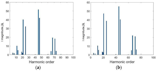
Figure 1.
Harmonic component of winding current of phase A under different slot openings: (a) slot opening = 2.0 mm and (b) slot opening = 7.0 mm.
The values of under each slot opening are shown in Table 2.

Table 2.
Parameters under different slot openings.
As the slot opening decreases, the leakage reactance of the motor increases, and does not change much, while decreases significantly, and also decreases accordingly. This shows that the increase in motor leakage reactance can restrain the ripple current of the winding current to a certain extent, and has a better filtering effect on the higher harmonic components of the winding current. However, the power factor of the motor decreases and the output power decreases. When the slot openings are 2.0, 4.0, and 7.0 mm, and other simulation calculation settings are the same, the air gap flux density of a pair of poles is shown in Figure 2. The x-coordinate d in Figure 2 refers to the circumferential distance of the air gap.
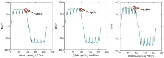
Figure 2.
Air gap flux density of two poles when the slot openings are different.
Figure 2 shows that because of the influence of the stator slotting and PWM excitation, the air gap flux density at the edge of the slot has a severe sudden change, with obvious spikes, and as the slot opening increases, the spikes decreases. The Fourier analysis results are shown in Table 3. It can be seen that the size of the slot opening has little effect on the low-order harmonics, and as the slot decreases, the 13, 23, and 25th harmonics decrease significantly.

Table 3.
FFT on air gap flux density.
The reason for the above is that the slot is reduced and the leakage reactance of the motor is increased, which has a better filtering effect on the high-order winding harmonics caused by the PWM wave. As a result, the high-order harmonic current causes the armature response to weaken, and the sudden change in the edge of the slot is correspondingly reduced.
4. PM Loss Calculation Results
The two-dimensional structure and finite element model of the prototype are shown in Figure 3.
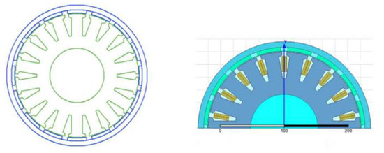
Figure 3.
Prototype structure and finite element model.
The eddy current loss in the permanent magnet is analyzed when the stator slot opening is in the no-load operation of the outer rotor permanent magnet synchronous machine, which varies from 2.0 mm to 7.0 mm. When the slot opening becomes larger, the effect of the stator slot opening on the flux density of the air gap increases, and the effect on the magnetic field density inside the permanent magnet increases, and the harmonic of the flux density increases, as shown in Figure 4 and Figure 5. It can be seen that, with the increase in slot opening, the distortion degree of the air gap flux density and flux density in the permanent magnet increases significantly. For example, in Figure 4, the contrast between the slot opening = 2.0 mm and the slot opening = 7.0 mm is the most obvious. When the slot opening = 7.0 mm, a large number of distortions appear in the air gap flux density.
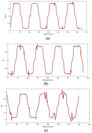
Figure 4.
The flux density of air gap under no-load condition: (a) slot opening = 2 mm, (b) slot opening = 4 mm, and (c) slot opening = 7 mm.
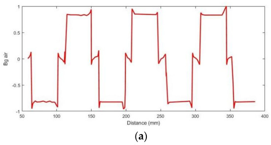
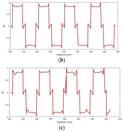
Figure 5.
Flux density in the permanent magnet under the no-load condition: (a) slot opening = 2 mm, (b) slot opening = 4 mm, and (c) slot opening = 7 mm.
The flux density distortion in the permanent magnet increases gradually with the increase in slot opening, as shown in Figure 5. At the same time, the total distortion of the flux density in the permanent magnet is large.
As slot opening changes, a change in eddy current density inside the permanent magnet occurs, and is shown in Figure 6. The maximum eddy current density of the permanent magnet increases with the slot opening, and the area occupied by the region with a high eddy current density gradually expands. When the slot opening is small, the eddy current corresponding to the whole magnetic pole appears in some high-density regions, but as the slot opening increases, the eddy current density in the corresponding region of the slot is much higher than that of the corresponding part of the magnetic pole, as shown in Figure 6c.
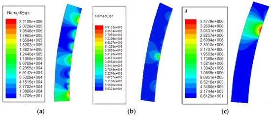
Figure 6.
The eddy current density in the permanent magnet under no-load condition. (a) slot opening = 2 mm (b) slot opening = 4 mm (c) slot opening = 7 mm.
Because of the change in slot opening, there is a change in eddy current loss of the permanent magnet, which is shown in Figure 7. The maximum eddy current loss density of the permanent magnet increases with the slot opening, from W/ to W/, and the area occupied by the high eddy current loss density increases gradually. Compared with Figure 7a,b, although the eddy current loss area in Figure 7a is larger than that in Figure 7b, the eddy current loss in Figure 7b is larger than that in Figure 7a. Therefore, the eddy current loss in Figure 7b is greater than that in Figure 7a.
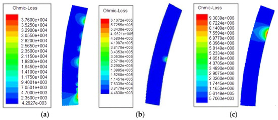
Figure 7.
Internal eddy current loss distribution of the permanent magnet: (a) slot opening = 2 mm (b) slot opening = 4 mm, and (c) slot opening = 7 mm.
Finally, the eddy current loss of the motor varies with the slot opening, as shown in Figure 8. When the slot opening is less than 3 mm, the eddy current loss of the permanent magnet caused by the slot opening is less than 20 W. This indicates that the eddy current loss of the rotor permanent magnet does not increase rapidly when the slot opening is small, although the slot opening increases. However, when the slot opening increases from 4 mm to 7 mm, the eddy current loss of the permanent magnet increases from 20 W to 87 W, indicating that the eddy current loss of the rotor permanent magnet increases at a faster rate with the slot opening increase during the period from 4–7 mm. When the slot opening continues to increase to 10 mm, the eddy current loss of the permanent magnet increases to 230 W, and there is a transition phenomenon in the eddy current loss of the rotor permanent magnet, indicating that when the slot opening is large, the eddy current loss of the rotor permanent magnet increases sharply, which should be avoided when considering the design. The reason may be that as the slot opening increases, the area of high eddy current density of the whole permanent magnet increases gradually, which causes the eddy current loss to rise sharply.
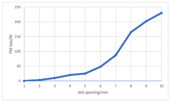
Figure 8.
The relationship between the rotor permanent magnet and slot opening under the no-load condition.
5. Conclusions
As the slot opening reduced, the leakage reactance of the motor increased, and the high-order winding harmonic current caused by the PWM wave was better filtered. The amplitude of the higher harmonic components of the air gap flux density was significantly reduced, and, finally, the eddy current loss of the permanent magnet was reduced. Although the increase in motor leakage reactance caused the power factor to decrease, the PWM excitation that decreased the power factor could be compensated for by increasing the input voltage. Therefore, in order to reduce the heating of the permanent magnets, the stator slot opening needs to be as small as possible or magnetic slot wedges need to be used in the design of permanent magnet synchronous machines for electric vehicles. However, the change in slot opening will not only affect the magnetic flux leakage of the winding, but also the equivalent air gap width. The reactance of the q-axis and d-axis will also change accordingly. This will further affect the cogging torque and torque characteristics of the motor, and the research in this area needs to be further deepened and improved.
Author Contributions
G.Y. conceived the proposed method, analyzed the data, and drafted the manuscript; X.W. (Xiaolu Wang) and C.Y. carried out the experiment; D.W. and H.W. contributed the analysis tools; X.W. (Xin Wang) provided some suggestions for drafting the paper. All authors have read and agreed to the published version of the manuscript.
Funding
This research received no external funding.
Conflicts of Interest
The authors declare no conflict of interest.
References
- Qiping, S. Study on High Power Density Permanent Magnet Synchronous Motor for Electric Vehicles Application; Shenyang University of Technology: Shenyang, China, 2012. (In Chinese) [Google Scholar]
- Ishak, D.; Zhu, Z.Q.; Howe, D. Eddy-current loss in the rotor magnets of permanent—Magnet brushless machines having a fractional number of slots per pole. IEEE Trans. Magn. 2005, 41, 2462–2469. [Google Scholar] [CrossRef]
- Kawase, Y.; Ota, T.; Fukunaga, H. 3-D Eddy current analysis in permanet magnet of interior permanent motors. IEEE Trans. Magn. 2000, 36, 1863–1866. [Google Scholar] [CrossRef]
- Xiangyong, X.; Jianghui, H.; Jibin, Z. Analytical calculation of rotor eddy current losses of surface-mounted PMSM. Electr. Mach. Control. 2009, 13, 63–66. (In Chinese) [Google Scholar]
- Takahashi, I.; Koganezawa, T.; Su, G.J. A super higher speed PM motor drive system by a quasi-current source inverter. IEEE Trans. Ind. Appl. 1994, 30, 683–690. [Google Scholar] [CrossRef]
- Yamazaki, K.; Shina, M.; Kanou, Y.; Miwa, M.; Hagiwara, J. Effect of eddy current loss reduction by segment of magnets in synchronous motors: Difference between interior and surface type. IEEE Trans. Magn. 2009, 45, 4756–4759. [Google Scholar] [CrossRef]
- Abu Sharkh, S.M.; Harris, M.R.; Irenji, N.T. Calculation of rotor eddy-current loss in high-speed PM alternators. In Proceedings of the Eighth International Conference on Electrical Machines and Drives, Cambridge, UK, 1–3 September 1997; pp. 170–174. [Google Scholar]
- Sharkh, S.A.; Irenji, N.T.; Harris, M. Effect of power factor on rotor loss in high-speed PM alternators. In Proceedings of the Ninth International Conference on Electrical Machines and Drives, Canterbury, UK, 1–3 September 1999; pp. 346–350. [Google Scholar]
- Sharkh, S.M.; Qazalbash, A.A.; Irenji, N.T. Effect of slot configuration and airgap and magnet thicknesses on rotor electromagnetic loss in surface PM synchronous machines. In Proceedings of the 2011 International Conference on Electrical Machines and Systems, Beijing, China, 20–23 August 2011; pp. 1–6. [Google Scholar]
- Qazalbash, A.; Sharkh, S.; Irenji, N. Rotor Eddy Current Power Loss in Permanent Magnet Synchronous Generators Feeding Uncontrolled Rectifier Loads. IEEE Trans. Magn. 2014, 50, 14379359. [Google Scholar] [CrossRef]
- Atallah, K.; Howe, D.; Mellor, P.H. Rotor loss in permanent-magnet brushless AC machines. IEEE Trans. Ind. Appl. 2000, 36, 1612–1618. [Google Scholar]
- Bianchi, N.; Bolognani, S.; Fornasiero, E. An Overview of Rotor Losses Determination in Three-Phase Fractional-Slot PM Machines. IEEE Trans. Ind. Appl. 2010, 46, 2338–2345. [Google Scholar] [CrossRef]
- Bianchi, N.; Fornasiero, E. Impact of MMF Space Harmonic on Rotor Losses in Fractional-Slot Permanent-Magnet Machines. IEEE Trans. Energy Convers. 2009, 24, 323–328. [Google Scholar] [CrossRef]
- Fornasiero, E.; Bianchi, N.; Bolognani, S. Slot Harmonic Impact on Rotor Losses in Fractional-Slot Permanent-Magnet Machines. IEEE Trans. Ind. Electron. 2012, 59, 2557–2564. [Google Scholar] [CrossRef]
- Etemadrezaei, M.; Wolmarans, J.J.; Polinder, H. Precise calculation and optimization of rotor eddy current losses in high speed permanent magnet machine. In Proceedings of the XXth International Conference on Electrical Machines, Marseille, France, 2–5 September 2012; pp. 1399–1404. [Google Scholar]
- Jianjun, L.; Yongxiang, X.; Jibin, Z. Rotor eddy-current loss of permanent magnet machine in brushless AC and DC modes, used for deep-sea HUV’s propeller. In Proceedings of the International Conference on Electrical Machines and Systems, Tokyo, Japan, 15–18 November 2009; pp. 1–4. [Google Scholar]
- Kawase, Y.; Yamaguchi, T.; Umemura, T. Effects of carrier frequency of multilevel PWM inverter on electrical loss of interior permanent magnet motor. In Proceedings of the International Conference on Electrical Machines and Systems, Tokyo, Japan, 15–18 November 2009; pp. 1–5. [Google Scholar]
- Kawase, Y.; Yamaguchi, T.; Yano, T. Three-Dimensional Loss Distribution Analysis of an Interior Permanent Magnet Motor Driven by PWM Inverter. In Proceedings of the 12th Biennial IEEE Conference on Electromagnetic Field Computation, Miami, FL, USA, 30 April–3 May 2006; p. 499. [Google Scholar]
- Markovic, M.; Perriard, Y. An Analytical Determination of Eddy-Current Losses in a Configuration with a Rotating Permanent Magnet. IEEE Trans. Magn. 2007, 43, 3380–3386. [Google Scholar] [CrossRef]
- Markovic, M.; Perriard, Y. Analytical Solution for Rotor Eddy-Current Losses in a Slotless Permanent-Magnet Motor: The Case of Current Sheet Excitation. IEEE Trans. Magn. 2008, 44, 386–393. [Google Scholar] [CrossRef]
- Zhu, Z.Q.; Schofield, N.K.; Howe, D. Analytical prediction of rotor eddy current loss in Brushless machines equipped with surface-mounted permanent. In Proceedings of the 5th International Conference on Electrical Machines and Systems, ICEMS’2001, Shenyang, China, 18–20 August 2001; pp. 806–809. [Google Scholar]
- Yubo, Y.; Xiuhe, W.; Changqing, Z. Effect of slot opening on the cogging torque of permanent magnet synchronous motor. Electr. Mach. Control. 2011, 15, 21–25. (In Chinese) [Google Scholar]
- Hongliang, Z. Iron Losses and Transient Temperature Field of Permanent Magnetic Synchronous Motor. Ph.D. Thesis, Harbin Institute of Technology, Harbin, China, 2010. (In Chinese). [Google Scholar]
- Yang, G.; Zhang, S.; Zhang, C. Analysis of Core Loss of Permanent Magnet Synchronous Machine for Vehicle Applications under Different Operating Conditions. Appl. Sci. 2020, 10, 7232. [Google Scholar] [CrossRef]
Publisher’s Note: MDPI stays neutral with regard to jurisdictional claims in published maps and institutional affiliations. |
© 2022 by the authors. Licensee MDPI, Basel, Switzerland. This article is an open access article distributed under the terms and conditions of the Creative Commons Attribution (CC BY) license (https://creativecommons.org/licenses/by/4.0/).