Article

An Improved Virtual Inertia Control Strategy for Low Voltage AC Microgrids with Hybrid Energy Storage Systems

1
College of Energy and Power Engineering, Inner Mongolia University of Technology, Hohhot 010051, China
2
College of Electric Power, Inner Mongolia University of Technology, Hohhot 010080, China
*
Author to whom correspondence should be addressed.
Energies 2022, 15(2), 442; https://doi.org/10.3390/en15020442
Submission received: 11 December 2021 / Revised: 5 January 2022 / Accepted: 7 January 2022 / Published: 9 January 2022
(This article belongs to the Special Issue Microgrids in Industry, Integration of Renewable Energy in Industry)

Abstract

:
This paper proposes a novel virtual inertia control (VIC) method based on a feedforward decoupling strategy to address the low inertia issue of power-converter-interfaced microgrids. The feedforward control scheme is employed to eliminate the coupling between active and reactive power caused by line impedance. The active power-voltage droop can be applied to the battery converter in the hybrid energy storage system (HESS). A novel VIC method is developed for the supercapacitor (SC) converter of HESS to increase the inertia of the microgrid. Detailed small-signal modeling of the SC converter with the proposed VIC was conducted, and the transfer function model was obtained. Parameter analysis of the virtual inertia and virtual damping was carried out with the pole-zero map method, and the step response characteristic of output voltage amplitude with power variation was analyzed in detail, deriving the parameter design principle. The simulation study verifies the effectiveness and validity of the proposed control strategy. The proposed feedforward decoupling method and VIC can be widely applied in microgrids to enhance inertia and improve their power quality.

1. Introduction

Microgrid (MG) is a novel way of distributed generation (DG) that utilizes clean, renewable energy sources (RESs) such as photovoltaics (PVs), wind turbine generators (WTGs), and energy storage systems (ESSs) [1]. MGs can be widely employed in the areas where buck grid power is not always available, such as rural areas or islands. It also can be used in urban areas or industry communities to save the energy consumption of factories. Droop control, as a decentralized control method, is widely applied in the microgrid for load power sharing among the RESs. The droop control usually uses a P-f, Q-V droop, and it mimics traditional synchronous generator characteristics. The application of this strategy is based on the assumption that the feeder lines between RESs and loads are inductive. However, this assumption is not always satisfied as the impedance in low and medium voltage power grids is often resistive or complex [2,3,4,5,6,7].
In a low voltage microgrid (LVMG), the P-V droop control is often applied [2,4]. In either the pure resistive or pure inductive grids, active power and reactive power are naturally decoupled. Nevertheless, when both the resistive component and the inductive component of line impedance are presented, active power and reactive power are coupled, i.e., the adjusting of active power will change the reactive power. Therefore, a decoupling procedure should be conducted to eliminate the coupling links.
One method is to change the output impedance of DGs with a virtual impedance scheme so that the overall impedance is resistive or inductive. In [2], a control method of the adaptive virtual resistance was applied in P-V droop control of parallel inverters to improve their power-sharing accuracy. In [3], active and reactive power was shared accurately in proportion for LVMG with an enhanced droop control strategy, but a communication link was still needed for sending the power references to RESs. In [4], an improved voltage droop control strategy is proposed, with only the local current in the dq frame. However, this method can only share the load with an equal ratio, and the dynamic response of the controller is not analyzed. In the general condition, the output impedance angle of the converter can be varied in a wide range so that the droop control method for different impedance conditions can be applied [5,6]. However, network impedance is neglected in these references. In [7], a virtual negative resistance is introduced to counteract the resistance component of line impedance so that the system impedance is mainly inductive. In [8], a novel complex impedance was adopted to facilitate the application of P-V droop control. In this method, a positive virtual resistance to strengthen the feeder resistance is introduced; a negative virtual inductance to counteract the line inductance can realize power decoupling. In [9], a control scheme is proposed to eliminate the inherent impedance of the converter, thus making the line impedance the only factor affecting the power-sharing. In [10], virtual impedance, having a positive resistive component and a negative inductive component, was employed to improve the accuracy of active power-sharing. For the above methods, the impedance should be accurately and swiftly measured for the online application [11]. Moreover, it tends to be a critical stable or unstable system if the virtual resistance is not properly designed.
A more convenient way to achieve the same effect is using a feedforward control strategy based on the R/X parameter. In [12], a feedforward controller was employed to address the distributed stabilization issue in AC MG. In [13], decoupling control was realized from an energy point of view. Other strategies can also be used for the decoupling aim. In [14], a novel nonlinear adaptive power decoupling control strategy based on a perturbation estimation method is proposed, achieving active power and reactive power control independently; the dynamic performance is also improved. Nevertheless, the mathematical models are comparatively complex for the above methods.
In a traditional power system, the synchronous generators are the contributors of inertia in the system. However, for the microgrid where DGs are integrated with power electronic converters, the inertia is reduced. This is a common phenomenon for both the AC and DC MG, which causes the power quality degradation when the DG and the load power fluctuate [15]. To mitigate the situation, the virtual synchronous generator (VSG) control strategy is introduced [16]. The VSG, as an effective way to improve the system inertia response, is widely used for virtual inertia and strengthened in MGs [17]. The VSG, which is generally called virtual inertia control (VIC), can give power support in the transient power-varying process. This strategy can improve the frequency response of the converter by proper optimization of parameters [18]. In [19], the performance of VIC was improved by fuzzy control combined with the VSG strategy. Essentially, the VIC can be applied in AC, DC, and hybrid AC/DC MGs [20]. In [21], VIC was applied in the grid-connected converter for supporting the inertia effect of the DC bus voltage. This indicates that virtual inertia can be mimicked through the control of voltage amplitude. In [22], a novel VSG was applied in a hybrid energy storage system (HESS), where the battery responds to the frequency variation part while the SC responds to the differential part of frequency.
Nevertheless, the conventional VSG strategy assumes that the line impedance is purely inductive, as in the high voltage grid, which often cannot be satisfied in mid-voltage or low-voltage MGs [23]. In these systems, the conventional VSG strategy is not effective. Hence, an improved VIC is needed in the LVMG where the line impedance is resistive and inductive. In [24], with virtual impedance introduced in the current control loop, the active and reactive power could be decoupled for both the droop and the VSG-controlled inverter. In [25], a new power decoupling strategy by integrating the constant virtual reactance in a wide frequency domain and current compensation loop is proposed. The system dynamic performance and stability were improved. Reference [26] proposes a virtual inductor-based strategy for decoupling active power and reactive power that only uses the q-axis voltage drop signal to generate the control command, thus reducing the computation burden.
However, all these strategies are only proper for a grid with a high X/R ratio. The realization of virtual inertia for P-V droop-controlled MGs remains a challenging issue to be addressed.
In this paper, a novel VIC control strategy is proposed for the SC converter to increase the inertia response in the P-V droop-controlled MG. To facilitate the application of the VIC, feedforward control is proposed for active and reactive power decoupling based on line impedance. Detailed parameter analysis is conducted to ensure the system’s performance and stability. A simulation study is conducted to verify the effectiveness of the proposed control strategy.
The contributions of this article are summarized as follows.
(1)
A new VIC strategy that takes the amplitude instead of the frequency of the converter is proposed and applied to the SC converter in the HESS. This strategy is proper for low-voltage P-V droop-controlled microgrids. The VIC can effectively mitigate the AC bus voltage fluctuation during the load power changing period. Moreover, the battery output power varying is also alleviated so that the lifecycle of it can be prolonged.
(2)
Considering a more general situation, the network impedance of microgrids has both resistive and inductive components. The voltage amplitude control of VSC will cause the active and reactive power to vary in the meantime. The coupling of active power and reactive power, caused by line impedance, is addressed with a feedforward decoupling control method. The proposed scheme can realize the complete decoupling of active and reactive power control, facilitating the application of the P-V droop strategy and VIC in the microgrid.
(3)
The dynamic power splitting of the HESS is realized. With the proposed strategy, the SC, with fast response dynamics, only provides transit power to fast fluctuation, while the battery, with a slow response time, gives consistent power support.
(4)
The proposed VIC does not influence AC bus frequency. The frequency remains at its rated value, improving the power quality in the microgrid.

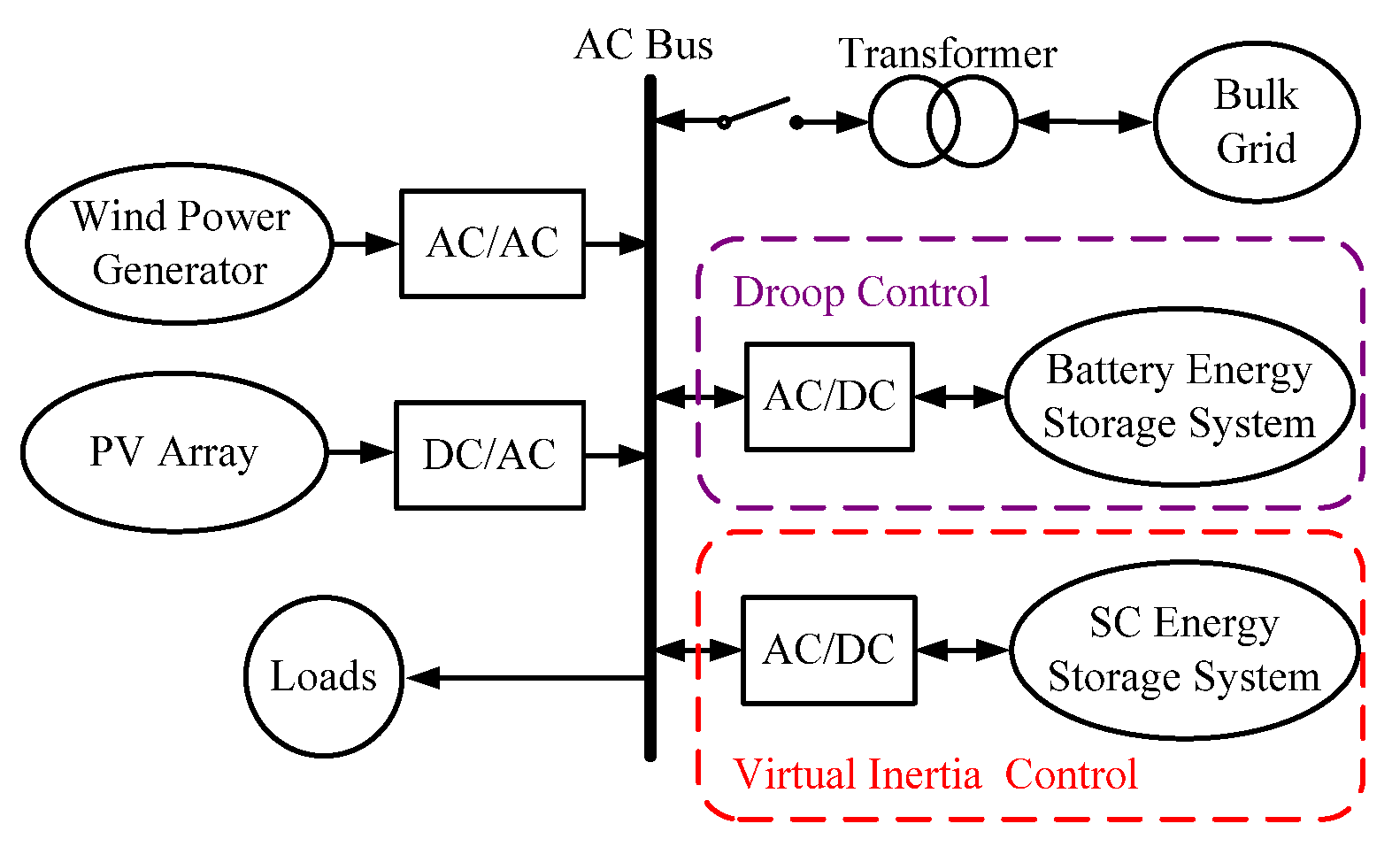
2. Topology and Control Principle of MG

2.1. Topology of MG

A typical MG is depicted in Figure 1, which includes a WTG, a PV array, loads, and an ESS. The ESS is integrated into the MG to diminish the power fluctuation of the MG, caused by the RESs. Due to the individual characteristics of different ESSs, the HESS is applied in the MG. As shown in Figure 1, the hybridization of the battery and supercapacitor (SC) is often used for the HESS in the practical application of the MG. All the RESs and ESSs are interfaced with the AC bus through the power electronic converters.

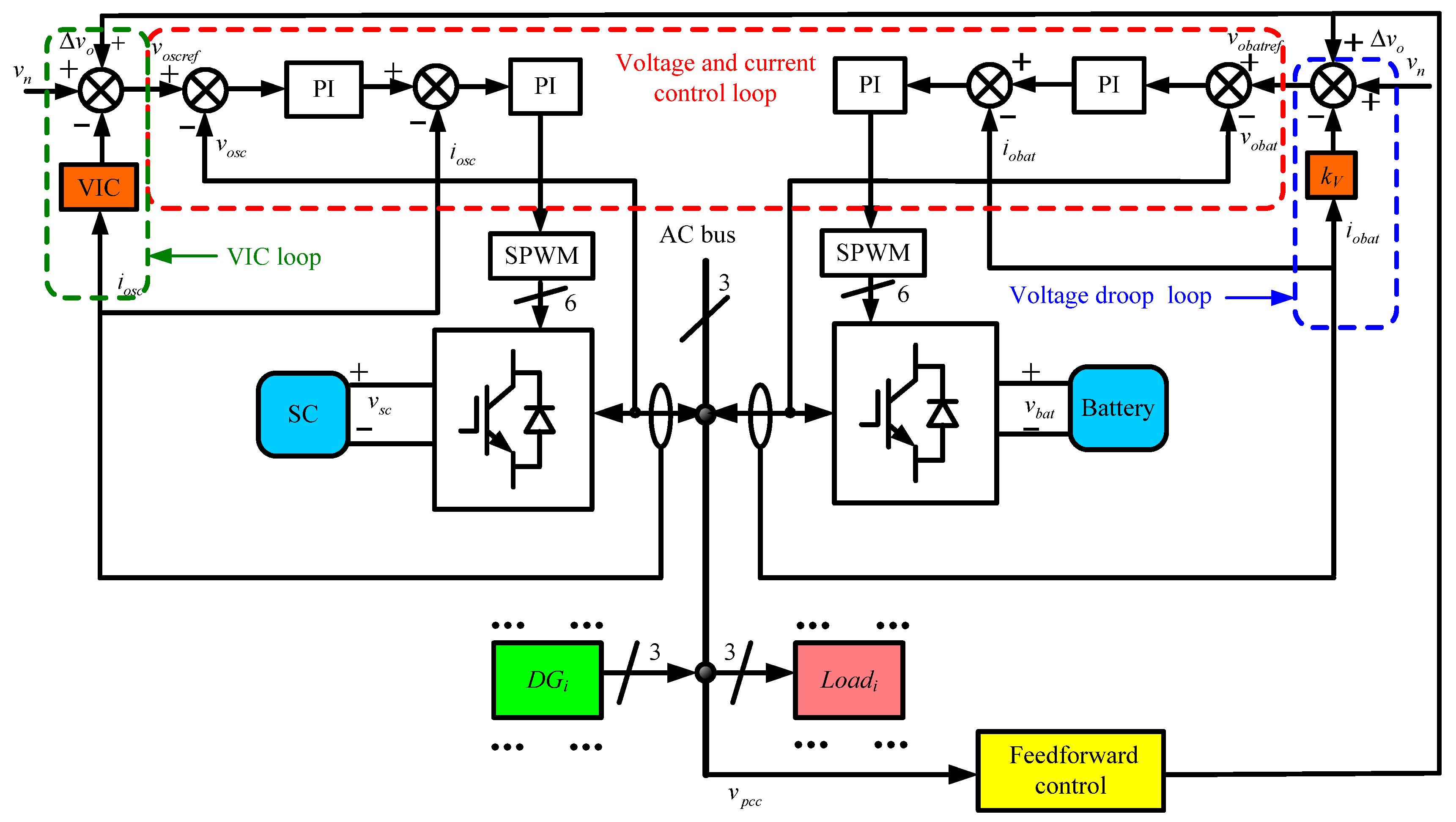
2.2. Control Principle of MG

The control of RESs and ESSs is essential for the proper and stable working of the MG, either in the grid-connected mode or islanded mode. In the grid-connected mode, the voltage and frequency are supported by the grid, and the main task of the MG is to utilize renewable energy efficiently. Therefore, the RESs work in the maximum power point tracking (MPPT) state. When the MG works in the islanded mode, the RESs should operate in either the MPPT mode or the limited power tracking (LPT) state, depending on the power balance condition of the MG and the state of charge (SOC) of the ESS. The control of the HESS depends on the converter control method. One of the methods is the master–slave control, in which the high pass filter (HPF) and low pass filter (LPF) are used to decompose the power fluctuations into high-frequency components and low-frequency components for the power control loop for the battery and SC [27]. Compared to the master–slave control, the droop control method is more widely investigated for its communicationless characteristic [28,29]. In a droop-controlled HESS, the output power of different ESSs is allocated automatically and locally [30].

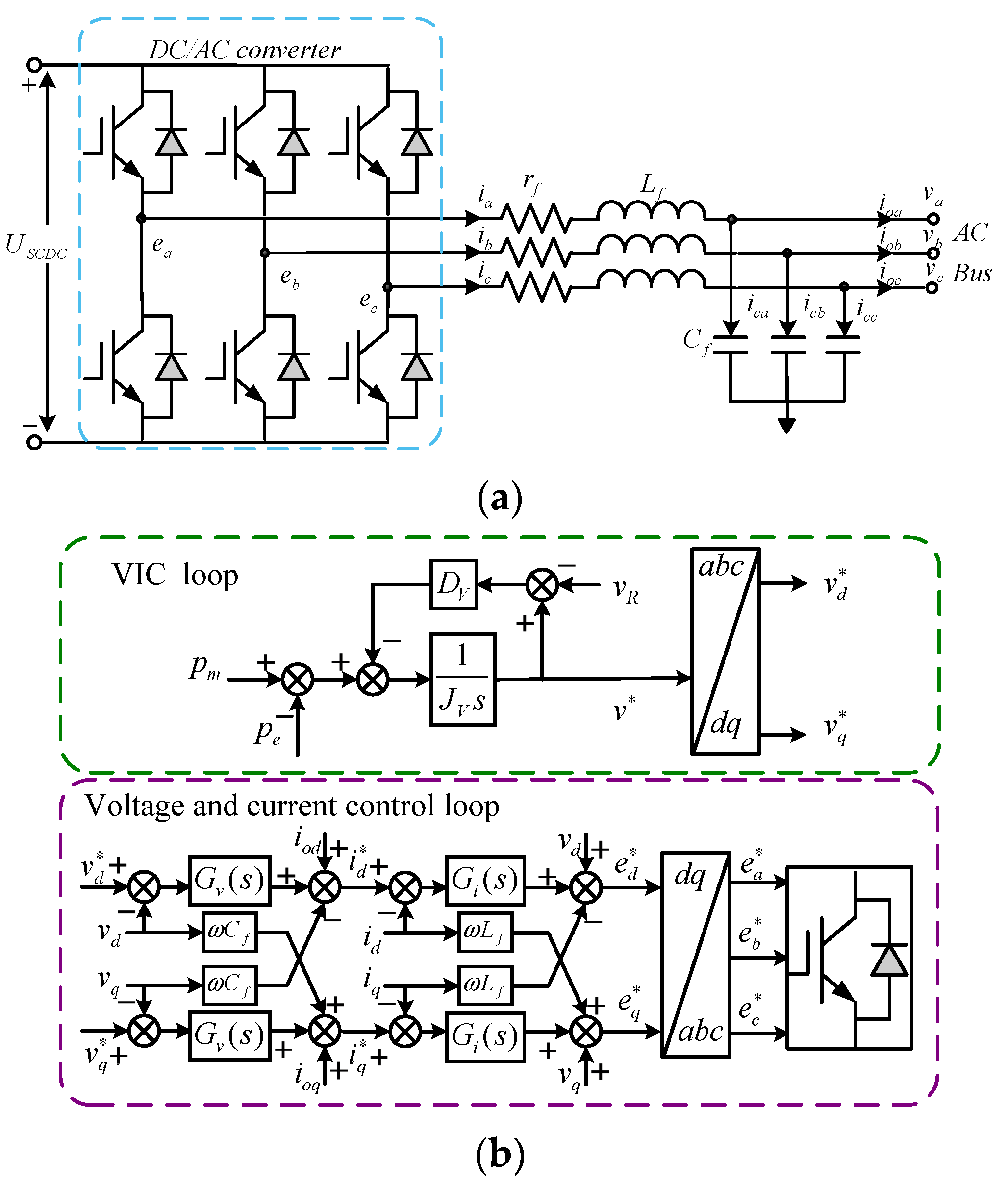
3. A Feedforward Decoupling-Based Virtual Inertial Control of SC Converter

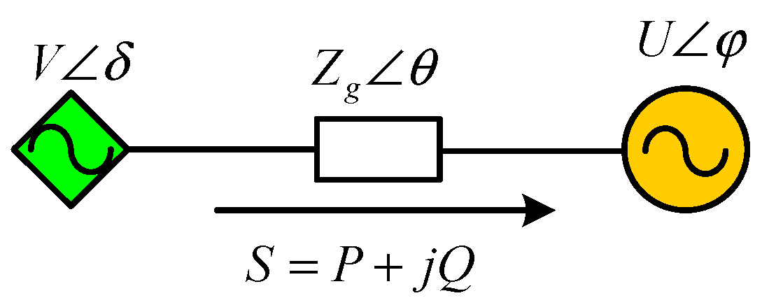
3.1. Droop Control of MG

In a power electronic-converter-connected MG, the DG can be viewed as a controlled voltage source connected to the AC bus through a feeder line, as depicted in Figure 2.
The complex power feeding from the converter to the AC bus can be expressed as
S = P + j Q = V δ × [ V δ U φ Z g θ ]
where P and Q are the active and reactive power; V and U are the voltage amplitude of the converter and the AC bus, respectively; δ and φ are the power angle of the converter voltage and the AC bus voltage; and Zg and θ are the magnitude and phase of the feeder line between the converter and the AC bus. The impedance of the feeder line can be written as
Z g θ = R g + j X g
where Rg and Xg are the resistance and reactance of the feeder line.
Substituting Equation (2) into (1), the active and reactive power can be rewritten as
P = V { R g [ V U cos ( δ φ ) ] + X g U sin ( δ φ ) } R g 2 + X g 2
Q = V { X g [ V U cos ( δ φ ) ] R g U sin ( δ φ ) } R g 2 + X g 2
Equations (3) and (4) express the power flow between the converter and the AC bus. In actual operation, the phase difference between the converter voltage and the AC bus is comparatively small. Thus, an approximate expression can be yielded as
sin ( δ φ ) δ φ
cos ( δ φ ) 1
In the high voltage grid where the line impedance is inductive, ignoring the resistance of the line, Equations (3) and (4) can be expressed as
P = V X g U ( δ φ )
Q = V X g ( V U )
Equations (7) and (8) show that a direct relationship between the converter active power P and the power angle error δ φ . The reactive power Q and the voltage difference V-U have a similar relevance [31].
Based on this assumption, the traditional droop control for the inductive lines can be expressed as
f = f 0 k p ( P P 0 )
V = V 0 k q ( Q Q 0 )
where V0 and f0 are the rated amplitude and frequency of converter voltage, and P0 and Q0 are the rated active power and reactive power at the rated voltage. P and Q are measured as output active power and reactive power; V and f are the calculated amplitude and frequency of the converter’s output voltage; and kp and kq are the droop coefficients of the amplitude and frequency of the droop controller. In the low voltage grid where the line impedance is resistive, ignoring the reactance of the line, Equations (3) and (4) can be expressed as
P = V R g ( V U )
Q = V R g U ( δ φ )
Assuming the AC bus voltage amplitude is stable, the active and reactive power transmissions from the converter to the AC bus can be controlled by the voltage amplitude difference and the voltage angle difference between the converter and the AC bus. On this basis, the droop control for the resistive lines can be described as
V = V 0 k p ( P P 0 )
f = f 0 + k q ( Q Q 0 )
As the power coupling effect of active and reactive power is caused by line impedance, the neglect of the resistive or reactive part of transmission lines in deriving the high or low voltage may reduce the effectiveness of the corresponding droop control strategy. Likewise, the assumption of constant AC bus magnitude cannot be satisfied all the time. The variation of it may induce a steady-state error in power output values when applying droop control strategies.

3.2. Power Decoupling Strategy Based on Feedforward Control

In low- and middle-voltage power grids, transmission line impedance is generally complex, which means both the resistance component and the inductance component exist in the line. This means that the influence of the coupled effects cannot be neglected. As Equations (3) and (4) are nonlinear, a linearization procedure is necessary. Let φ = 0, and suppose the equivalent voltage is V0 and the phase angle is δ0, then the small-signal model of a power transmission model for the feeder line can be expressed as
[ Δ P Δ Q ] = [ P V P δ Q V Q δ ] [ Δ V Δ σ ]
where
{ P V = U R g cos δ 0 + U X g sin δ 0 R g 2 + X g 2 P δ = V 0 U X g cos δ 0 V 0 U R g sin δ 0 R g 2 + X g 2 Q V = U X g cos δ 0 + U R g sin δ 0 R g 2 + X g 2 Q δ = V 0 U R g cos δ 0 V 0 U X g sin δ 0 R g 2 + X g 2
Equation (15) shows that the variation of active power and reactive power is influenced by both the change of amplitude and the angle of the converter output voltage. Therefore, a decoupling process is needed to realize the voltage magnitude to control the active power and the power angle of the voltage to control the reactive power.
The proposed feedforward decoupling scheme based on the above model in (15) is depicted in Figure 3.
In Figure 3, it can be seen that a change in the voltage will not only influence the output active power but also alternate the reactive power. The varying of both reactive-power and active-power angles can change both the reactive power and the active power. In order to realize the decoupling target that has a magnitude only to adjust active power and a power angle only to control reactive power, a feedforward control scheme is employed. The feedforward coefficients GFδV and GFVδ will eliminate the coupling links between the voltage to reactive power and the angle to active power, which can be expressed as
{ G F δ V Q δ + Q V = 0 G F V δ P V + P δ = 0
From Equations (15) and (16), and with the approximate condition, the feedforward coefficients are derived as
{ G F δ V = Q V / Q δ X g V 0 R g G F V δ = P δ / P V V 0 X g R g
From Equation (17), it can be seen that the decoupling coefficients mainly depend on the output voltage and the line impedance.

3.3. Virtual Inertia Control of SC

The traditional VSG obtains a mimic model of the SG in power plants, and the dynamic equation (also called the swing equation) is
J d ω d t = p m p e D ( ω ω n )
where pm and pe are the rated and output power of the VSG, and ω and ωn are the actual and rated angular frequencies of the VSG. J and D are the virtual inertia and damping coefficient of the VSG. The proper application condition of Equation (18) is reactive line impedance, which is not the case in low-voltage microgrids. Hence, the control strategy in (18) should be improved to adapt to the resistive line. In P-V droop-controlled MGs, the amplitude of the bus voltage, instead of frequency, is the benchmark variable of the active power balance in the grid. Therefore, the proposed VIC strategy should take the voltage magnitude to replace the voltage frequency as the controlled index variable. Moreover, the improved VIC should have a similar form with Equation (18) so that the inertial dynamic performance can be imitated. Based on the control strategy in (18), a novel inertial control strategy, proper for low-voltage microgrids, is proposed and expressed as
J V d v d t = p m p e D V ( v v R )
where JV and DV are the virtual inertia and the damping coefficient; v* and vR are the amplitude of output voltage and the rated voltage of the converter. In Equation (19), the proposed VIC strategy introduces virtual inertia by varying the amplitude of converter voltage instead of frequency, conforming to the transmission features of the low-voltage feeder line.
Based on the above VIC strategy, a control block diagram is depicted in Figure 4, where the multi-loop structure is employed; the outer loop is the VIC loop in which the VIC in (19) is integrated; the inner loop is the voltage and the current control loop in which the amplitude of voltage reference is from the outer loop output.
In the synchronous reference frames (SRFs), the mathematical formula of the SC converter in Figure 4a is described as
{ v d = ( r f + L f p ) i d + ω L f i q + e d v q = ( r f + L f p ) i q ω L f i d + e q
where p is the differential operator, vd and vq are the d- and q-axis components of the AC bus voltage in the SRFs, ed and eq are the d- and q-axis components of the converter voltage before the LC filter, rf and Lf are resistance and inductance of the converter LC filter, and ω is the angular frequency of the AC bus.
Equation (20) shows that the variables in SRFs are coupled, causing it to be difficult to properly design the controller. Here, in order to control the filter current and decouple the coupled components, a PI controller is employed and expressed as
G i ( s ) = K i p + K i i s
where Kip and Kii are the proportional and integral coefficients of the current controller.
The current control equation can be represented as
{ e d = G i ( s ) ( i d i d ) ω L f i q + v d e q = G i ( s ) ( i q i q ) + ω L f i q + v q
Substituting Equation (22) into (20), the current can be controlled as
{ ( r f + L f p ) i d = G i ( s ) ( i d i d ) ( r f + L f p ) i q = G i ( s ) ( i q i q )
The corresponding equation in the SRFs of the filter capacitor is also obtained with Kirchhoff’s current law, written as
{ i o d = C f p v d + ω C f v q + i d i o q = C f p v q ω C f v d + i q
where iod and ioq are the d- and q-axis components of the converter output current. Cf is the capacitance of the LC filter.
The voltage control equation can be represented as
{ i d = G v ( s ) ( v d v d ) ω C f v q + i o d i q = G v ( s ) ( v q v q ) + ω C f v q + i o q
where v*d and v*q are the d- and q-axis components of output voltage. The voltage controller used here is
G v ( s ) = K v p + K v i s
where Kvp and Kvi are the proportional and integral coefficients of the voltage controller.
Substituting Equation (25) into (24), the voltage can be controlled as
{ C f p v d = G v ( s ) ( v d v d ) C f p v q = G v ( s ) ( v q v q )
The above deduction processing shows that with the control strategies in (22) and (25), the voltage and current of the SC converter in the dq frame can be decoupled and controlled independently, as shown in Equations (23) and (27).

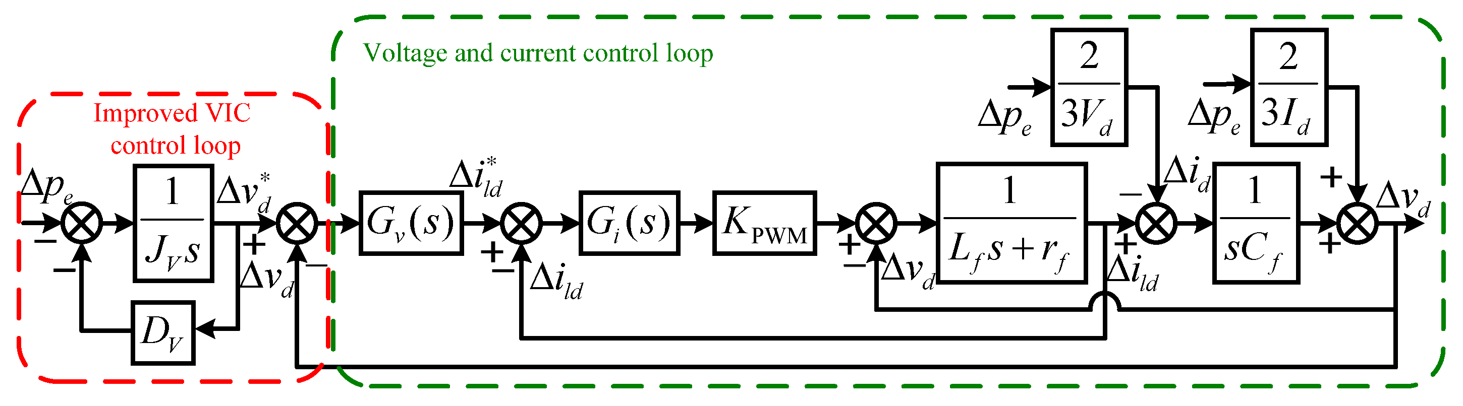
4. Modeling and Parameter Design of VIC

4.1. Small-Signal Modeling of the SC Converter

To obtain the dynamic relationship between the output power perturbation and the voltage fluctuation, a small-signal model is needed. Ww write the state variables in Equation (20) as the sum of equivalent point values and small perturbations as
{ i d = I d + Δ i d i q = I q + Δ i q v d = V d + Δ v d v q = V q + Δ v q
Eliminating the steady-state values and applying Laplace transformation, then the corresponding small-signal model of Equations (23) and (27) can be expressed as
{ Δ i d ( s ) = ( Δ i d ( s ) Δ i d ( s ) ) G i ( s ) / ( s L f + r f ) Δ i q ( s ) = ( Δ i q ( s ) Δ i q ( s ) ) G i ( s ) / ( s L f + r f )
{ Δ v d ( s ) = ( Δ v d ( s ) Δ v d ( s ) ) G v ( s ) / s C f Δ v q ( s ) = ( Δ v q ( s ) Δ v q ( s ) ) G v ( s ) / s C f
In SRFs, the output power of a 3-phase converter is written as
p e = 3 2 ( v d i d + v q i q )
Substituting Equation (28) into (31), eliminating the steady-state variables and ignoring the second-order variations, then Equation (31) can be written as
Δ p e = 3 2 ( V d Δ i d + Δ v d I d + V q Δ i q + Δ v q I q )
With the AC bus voltage-oriented control employed, vq is equivalent to zero in steady-state. Suppose the converter is working at unit power mode, which means the converter only supports active power in normal conditions. Then, iq is also equivalent to zero in this situation, and Equation (32) can be simplified as
Δ p e = 3 2 ( V d Δ i d + Δ v d I d )
With the superposition theorem, ignoring the fluctuation component Δvd and applying the Laplace transformation to Equation (33), the relation between Δid(s) and Δpe(s) is given as
Δ i d ( s ) Δ p e ( s ) = 2 3 V d
Similarly, the relation between Δvd(s) and Δpe(s) is obtained as
Δ v d ( s ) Δ p e ( s ) = 2 3 I d
Conducting the small-signal decomposition, Equation (19) can be rewritten as
J V d Δ v d t = Δ p e D V Δ v
where Δv* is the perturbation of v*, and with the voltage-oriented control, v* is equal to vd.
Applying Laplace transformation, Equation (36) becomes
Δ v ( s ) = 1 J V s ( Δ p e ( s ) + D V Δ v ( s ) )
With the above control diagram in Figure 4, based on Equations (29)–(37), the small-signal model of the SC converter is built, as shown in Figure 5, so that dynamic performance and stability analysis can be conducted. The small-signal model of the SC converter control system also has a cascade structure. It should be noted that the input variable is changed to the varying of SC output power Δpe, which is one of the main variables of the following analysis.
Form Figure 5, the transfer function of the SC converter is derived as
T v p ( s ) = Δ v d Δ p e = d 0 s 4 + d 1 s 3 + d 2 s 2 + d 3 s + d 4 n 0 s 5 + n 1 s 4 + n 2 s 3 + n 3 s 2 + n 4 s + n 5
where the coefficients of the transfer function are
{ d 0 = 2 J V L f d 1 = 2 L f r f 2 D V L f 2 L f K i p K P W M d 2 = 2 D V r f 2 D V K i p K P W M 2 J V K i i K P W M 3 K i p K P W M K v p V d 3 = 2 D V K i i K P W M 3 K i i K P W M K v p V d 3 K i p K P W M K v i V d d 4 = 3 K i i K P W M K v i V d { n 0 = 3 C f J V L f V d n 1 = 3 C f D V L f V d + 3 C f J V V d r f + 3 C f J V K i p K P W M V d n 2 = 3 J V V d + 3 C f D V V d r f + 3 C f D V K i p K P W M V d + 3 C f K i i K P W M V d + 3 J V K i p K P W M K v p V d n 3 = 3 D V V d + 3 D V K i i K P W M V d + 3 D V K i p K P W M K v p V d + 3 J V K i i K P W M K v p V d + 3 J V K i p K P W M K v p V d n 4 = 3 D V K i i K P W M K v p V d + 3 D V K i p K P W M K v i V d + 3 J V K i i K P W M K v i V d n 5 = 3 D V K i i K P W M K v i V d
The physical meaning of transfer function (38) is the dynamic variation of converter voltage amplitude under the varying of output active power. It should be noted that with voltage-oriented control, the q component of voltage magnitude is set to zero. Therefore, only the d component appears in the small-signal model.
The general control diagram of the HESS with the proposed control strategy is given in Figure 6, which is structured with a multi-loop form. The outer loop is the feedforward control loop and the virtual inertia control loop as well as the droop control loop; the inner loop is the traditional voltage and current control loop.

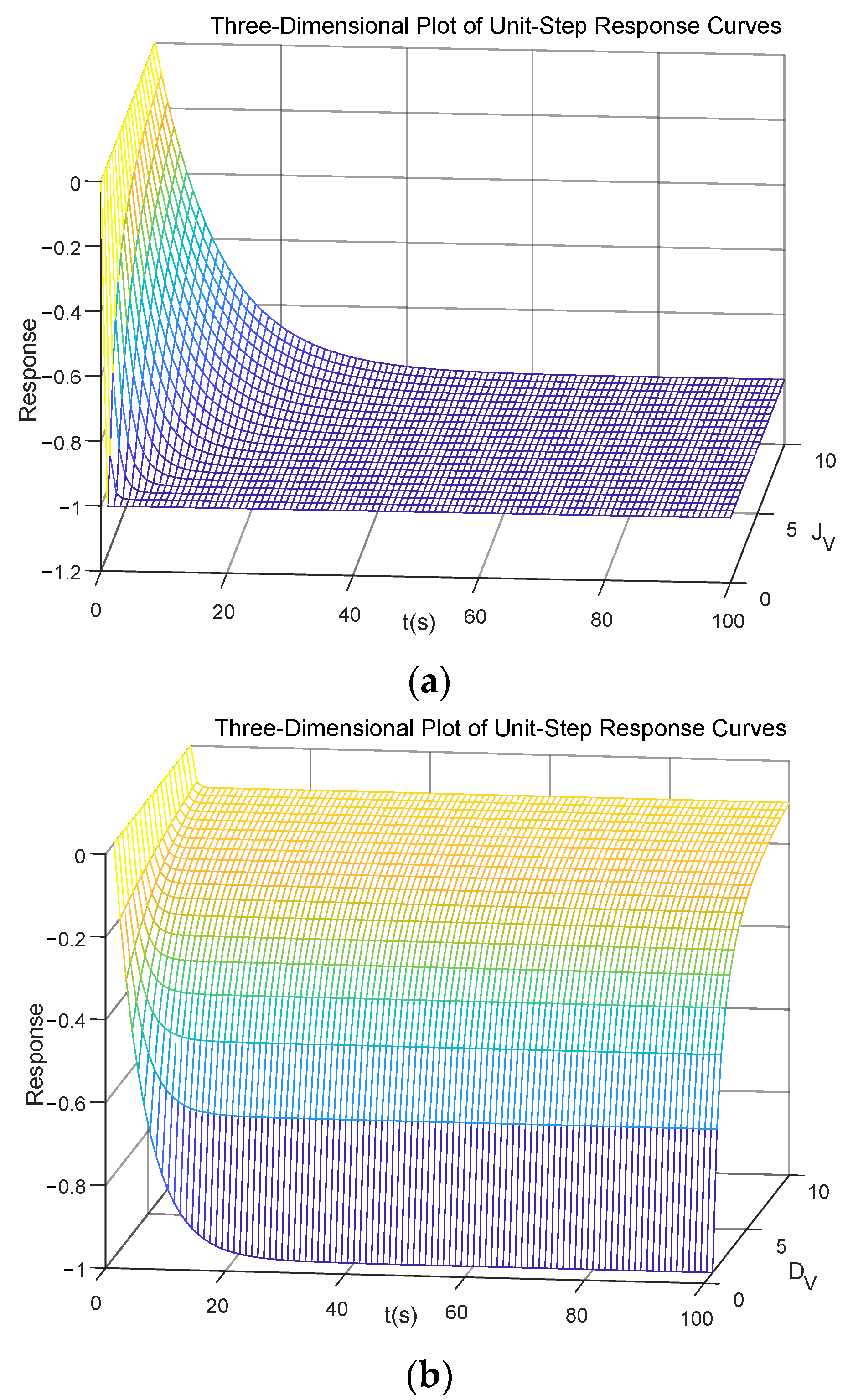
4.2. Dynamic Performance Analysis and Parameter Design
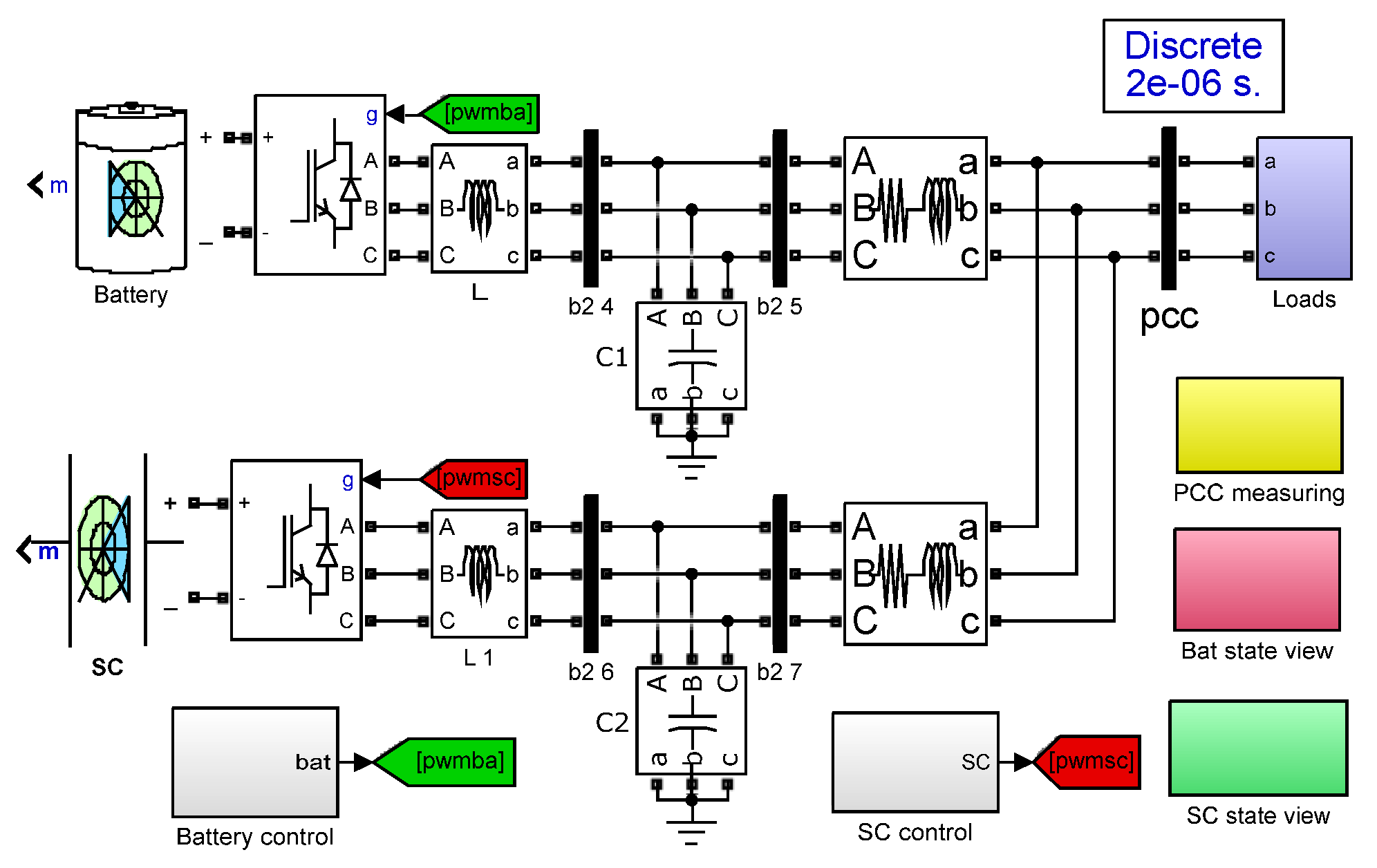
In order to obtain the proper dynamic performance and stability, the influence of the virtual inertia parameters should be analyzed. The zeros and dominant poles are depicted in Figure 7 with the changing parameters of JV and DV.
As can be seen from Figure 7, there are two pairs of dipoles in each subplot, and these dipoles are not near the origin point. Hence, their influence on the system response can be neglected. In Figure 7a, with JV changing, a single dominant pole is moving. When JV ≥ 0, the pole moves toward the origin point of the coordinate, with an increase of it on the left side of the s-plane but not crossing it, ensuring system stability. However, the pole will be on the right side of the s-plane if JV ≤ 0, so the system is unstable in this situation. Therefore, JV ≥ 0 is the condition of system stability. Nevertheless, the bigger JV means a smaller stability margin. Therefore, there is a tradeoff between stability and system inertia capacity. Figure 7b shows that the solo dominant pole will migrate far away from the origin point with DV increasing. Hence, the bigger JV means bigger inertia in the MG and a better suppression of the impact to the MG caused by the power fluctuation of RESs and loads. Moreover, bigger inertia will make the dynamic response slow down. Conversely, the smaller JV weakens the converter’s ability to suppress the voltage fluctuation. Therefore, based on the above analysis, the value of JV should be selected according to the MG’s inertia requirement and response time. As DV has a coefficient with JV, the selection of DV should be further analyzed with other methods such as step responses in the time domain.
The step responses of Tvp with changing JV and DV are given in Figure 8, which shows the dynamic processes of the AC bus voltage amplitude with the SC converter under sudden output power increases. As can be seen from Figure 8a, when JV is small, the responses of Tvp are fast, and ΔV soon reaches the final value; when JV is bigger, the responses are slower, indicating that the bigger JV can increase system inertia. It also can be seen that the final value of the response is equal, indicating the independence of JV to the final value. Figure 8b shows that with the increase of DV, the response is quicker, which means the inertia is weaker. Moreover, the final value of the response is also different. The bigger DV makes the final value smaller. The step response dynamics match the above analysis in Figure 7.
Therefore, the set of JV and DV should comprehensively consider the inertia capacity, the response time, and the final value of the response. The guidance from the above analysis is to set JV as big as possible under the condition of ensuring system stability and SC capacity and to set DV as small as possible to make a bigger voltage variation so that the SC only gives power at the transit process.

5. Simulation Study

In order to verify the effectiveness of the control strategies proposed in this paper, a microgrid consisting of a HESS, power converters, and loads was built in the MATLAB/Simulink according to Figure 1, as shown in Figure 9. There are battery and SC models and their DC/AC converters with LC filters, which are connected with loads through line impedance. To facilitate the simulation, the controllable load is employed to represent the equivalent power error between the DGs and the loads. There are also control and measuring blocks integrated into the simulation environment.

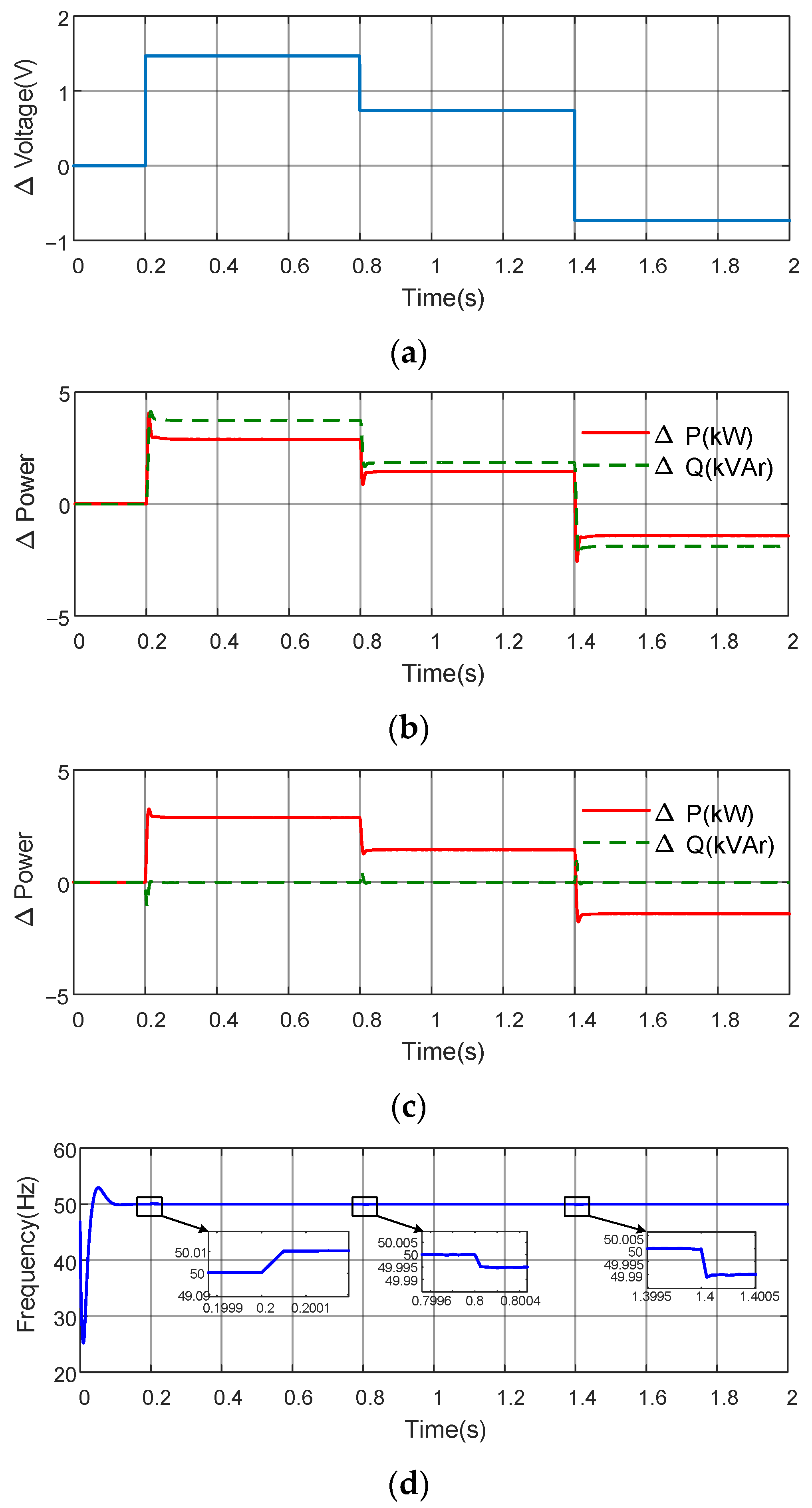
5.1. Case A: Active Power and Reactive Power Decoupling Control

In order to verify the effectiveness of the feedforward decoupling control strategy, the model depicted in Figure 2 is built, which employs the control strategy in Figure 3. The main system parameters are listed in Table 1.
The feedforward coefficients are calculated with Equation (17). Here, the voltage amplitude of the grid is 311 V. The simulation results, with and without the feedforward control, are depicted in Figure 10, respectively. In Figure 10, the simulation time is 2 s. The voltage change ΔV is zero at the start of the simulation and then varied at 0.2, 0.8, and 1.4 s to 1.5, 0.8, and −0.8 V, respectively, as shown in Figure 10a. As can be seen from Figure 10b, without the decoupling control applied, the active power and the reactive power are changing instantaneously with varying converter voltage. This means that the voltage can control the active power in complex line impedance conditions, but the coupling component makes the reactive power also vary, and this is not the dedicated aim. Thus, the decoupling method should be employed. In Figure 10c, after the feedforward control is applied, the active power has the same profile as in Figure 10b, while the reactive power keeps at zero. The active power and the reactive power are completely decoupled. During all these adjusting processes, the converter output frequency keeps at 50 Hz except for some variations of no more than 0.01 Hz at the voltage changing time points, as is illustrated in Figure 10d. This verifies that the proposed feedforward control can effectively decouple the active and reactive power without influencing output frequency.

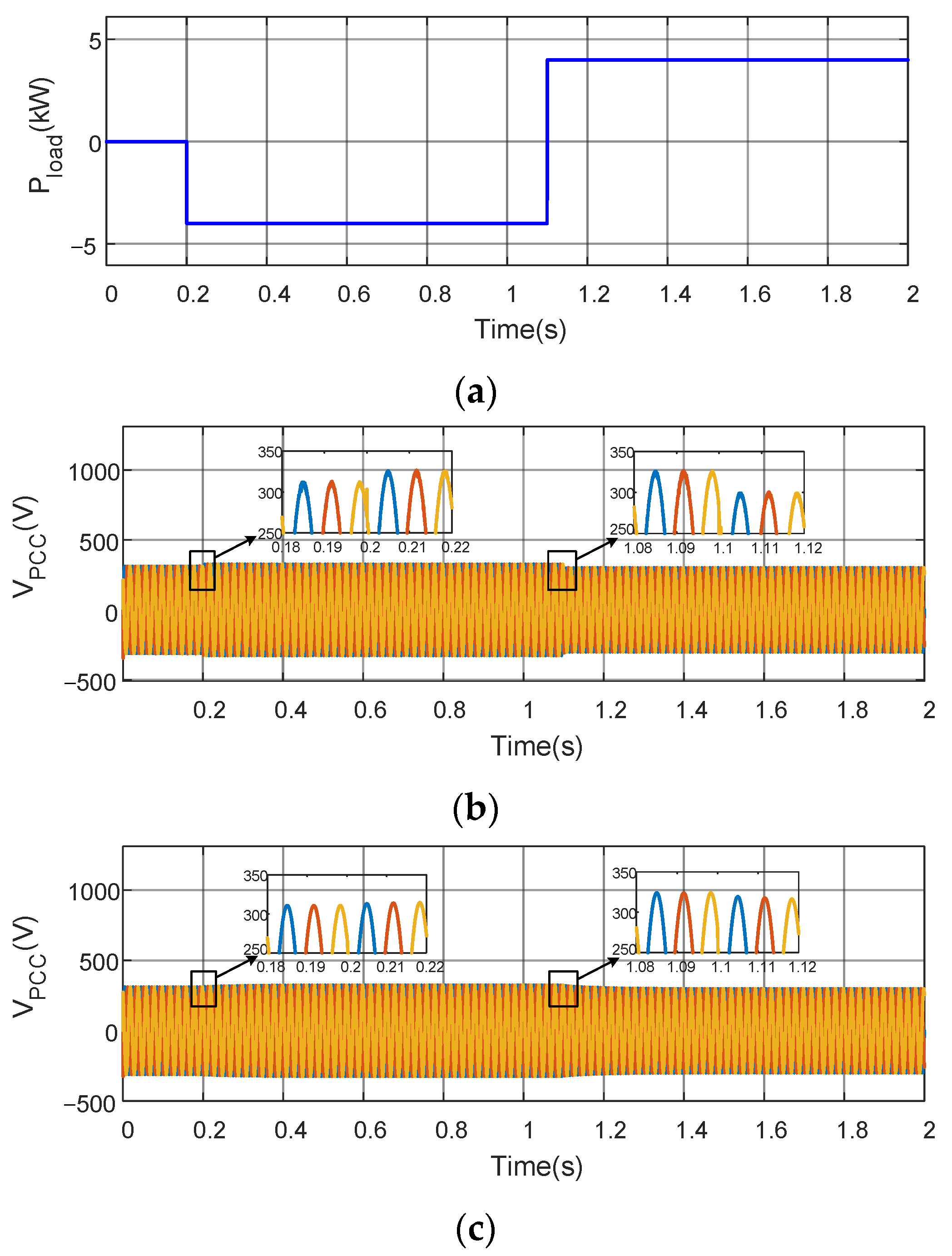
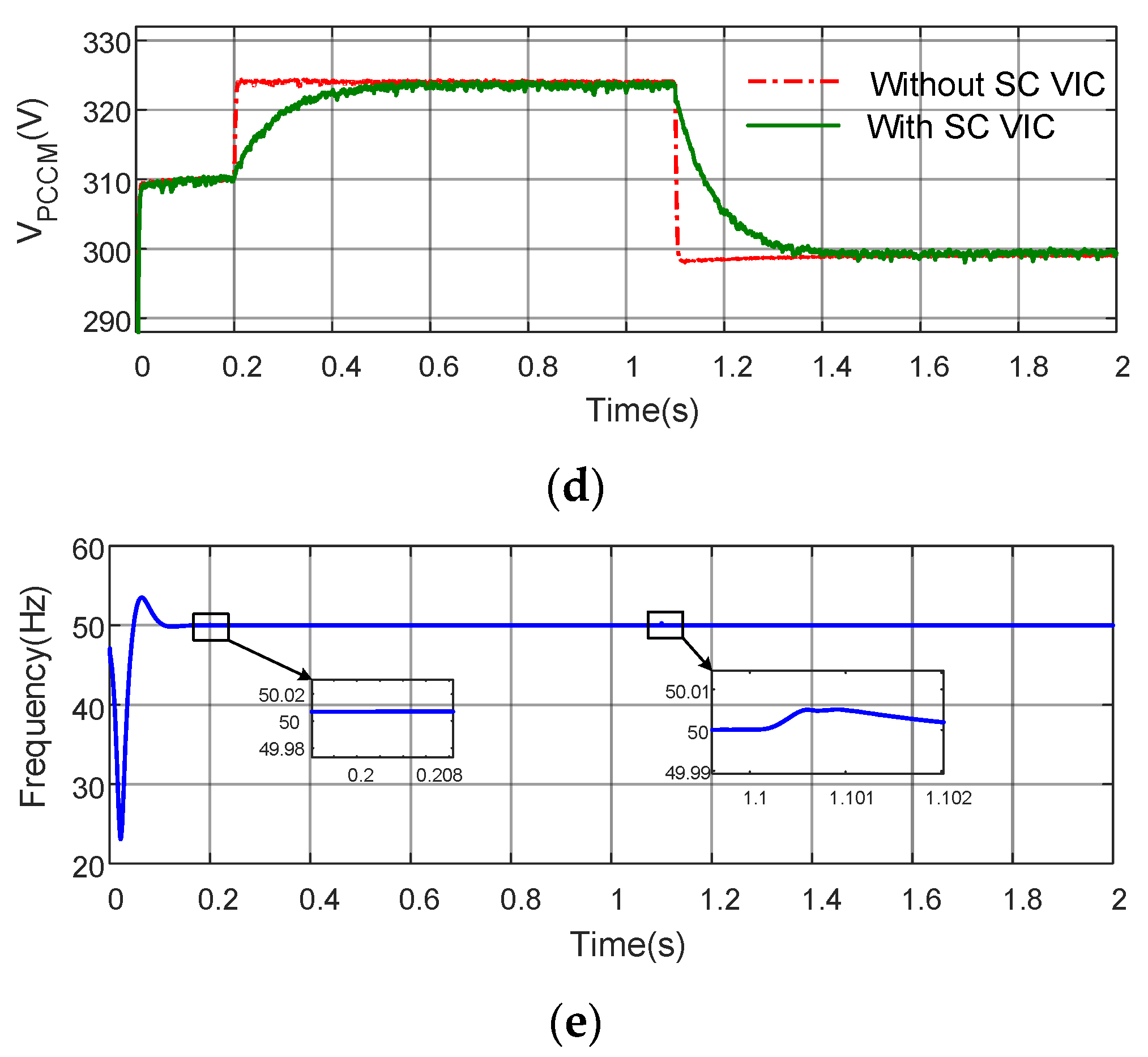
5.2. Case B: AC Bus Voltage Fluctuation Smoothing

In this case, the AC bus voltage is monitored to observe the effect of virtual inertia support. The main system parameters are listed in Table 2.
Figure 11 shows the AC bus voltage response with and without inertia control in the SC converter under load variation. The equivalent load power, defined by the difference between the DGs’ power and load power, decreases to −4 kW at 0.2 s and increases to 4 kW at 1.1 s, as denoted in Figure 11a. Figure 11b,c display the waveforms of the AC bus with and without SC VIC support. In Figure 11b, without SC VIC employed, the AC bus amplitude will suffer a sudden change as the load power function happens. On the contrary, the AC bus voltage will gradually move toward its final value when the SC VIC is applied, as presented in Figure 11c. A detailed comparison of the AC bus magnitude with different control strategies is exhibited in Figure 11d. The AC bus voltage, which indicates the power balance of the MG, is maintained at its no-load value of 311 V when the equivalent power is zero and reaches 324 and 298 V when a system power surplus or deficit occurs. This is in accordance with the aforementioned P-V droop strategy. Nevertheless, the voltage profile is distinct with and without VIC, even though the final value is the same. Without the virtual inertia control, the AC bus voltage would soon reach a steady-state value under the load power changing. This short period of voltage changing may trigger the action of the protective device, thus causing the interruption of the power supply in the MG. Conversely, with the virtual inertia control applied, the AC bus voltage changes to the value equaling the inertia-absent condition slowly. In this simulation, the AC bus frequency maintains at 50 Hz, and only a little perturbation of no more than 0.01 Hz appears when the load power changes. Hence, the AC bus voltage profile is improved under load disturbance.
In the above simulation, the fluctuation of AC bus frequency with the proposed VIC is smaller than the methods with traditional VSG in [9,22,24]. The simulation results of frequency in both Figure 10d and Figure 11e show that under either Case A or Case B, the fluctuation of frequency is less than the traditional VIC strategy proposed in [32].

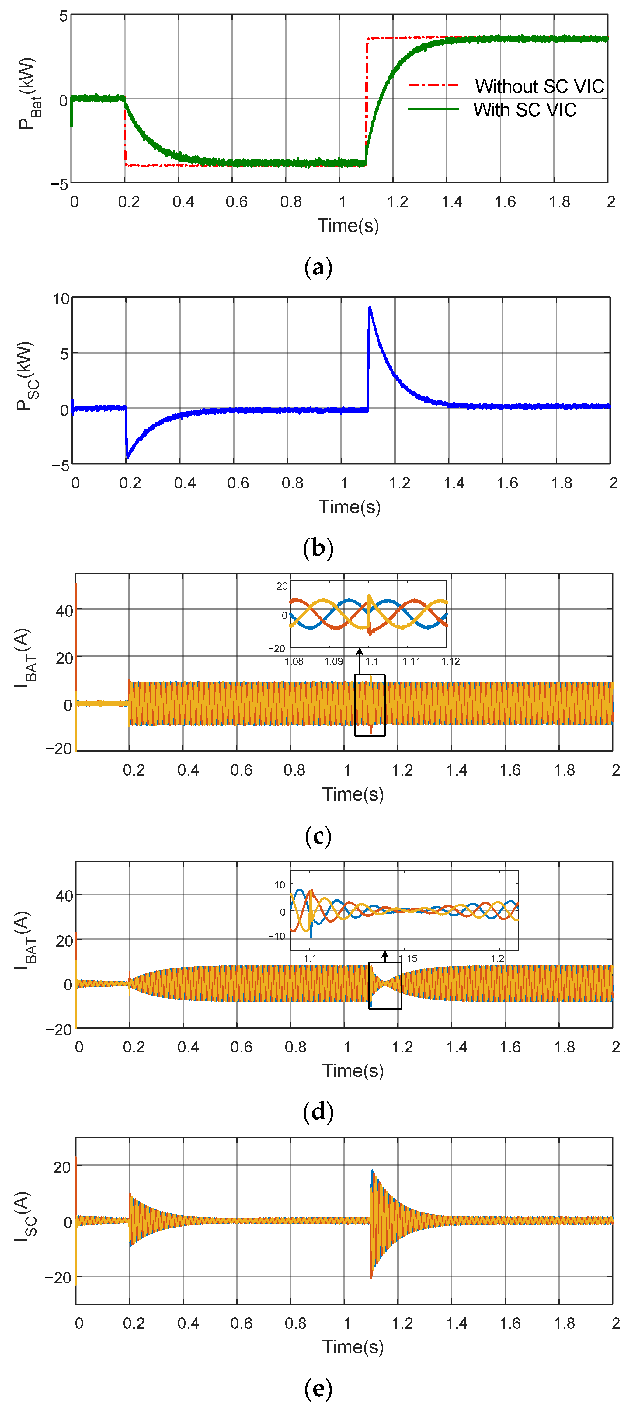
5.3. Case C: Virtual Inertia Support during Power Fluctuation

In this case, the output power of the battery and SC are measured to exhibit the dynamic power response. Figure 12 shows the responses of the battery and SC with and without VIC. In this case, the same equivalent load as in Case B is applied. As seen in Figure 12a, the battery output power is equal to the equivalent load power all the time without VIC. This means that the battery, as the main power source in the MG, must respond quickly to the equivalent load power changing to keep the power balance in the system under the condition of VIC absence. Figure 12b shows that when the load power is changing, the SC with virtual inertia control will soon output a transient power approximately equal to the changing value of equivalent power to the AC bus to mitigate the AC bus voltage drop. Then, after a short period of adjustment, the SC power gradually drops to zero in exponential form. This is in accordance with the low energy intensity and high power intensity performances of the SC. Compared to the SC converter power, the battery output power rises gradually to the load power and becomes equal to the load power in the steady-state. The benefit of the gradual rising in battery power is that the lifecycle of the battery can be prolonged as the sudden load power fluctuations are alleviated. Figure 12c,d exhibit the battery converter output current. The output current rises swiftly at 0.2 s when the load increases, and the phase is inversed at 1.1 s when the load power changes from minus to plus without SC VIC, as shown in Figure 12c. On the contrary, the results in Figure 12d manifest that the current varies more slowly with SC VIC applied. The reason is that the SC converter output current rises quickly at the load power changing time points, as shown in Figure 12e. The frequency value is the same as in Case B and is not presented here.

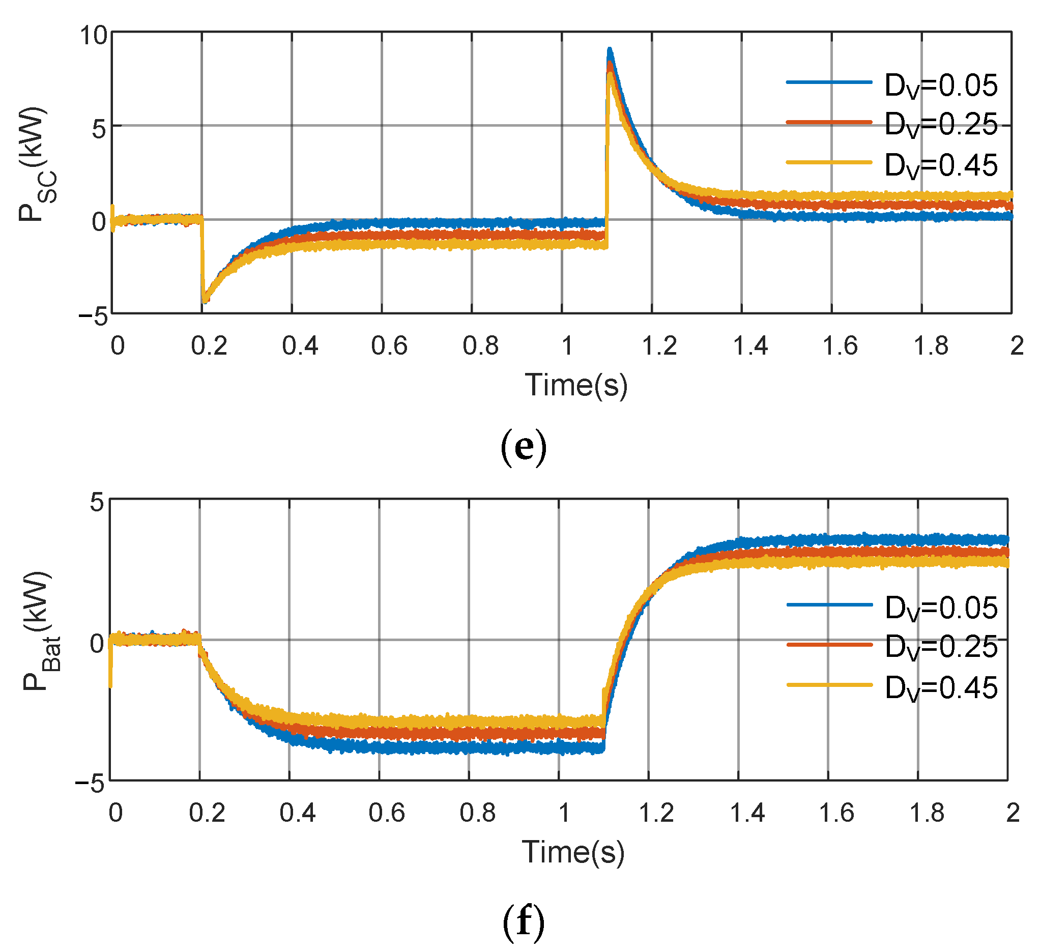
5.4. Case D: Dynamic Responses of HESS with Different Virtual Inertia and Damping

In this case, the output power of the battery and SC are measured to exhibit the dynamic power response with different values. The simulation conditions are the same as in the above work. Figure 13a–c show the simulation results of PCC voltages, the battery, and SC output power with different JV when DV keeps at 0.05. It can be seen from the figure that with the increase in JV, the dynamic responses become slower, which means that the system inertia is strengthened. Moreover, the variation of JV does not influence the steady-state values of AC bus voltage amplitude as well as the output power of the battery and SC.
Figure 13d–f show the dynamic responses of PCC voltages, the battery, and SC output power, respectively, with different DV when JV keeps at 0.1. It is viewed in the figure that the changing of DV will bring about the steady-state values varying without a significant modification of dynamic processes. Bigger DV leads to little perturbation in PCC voltage. Moreover, the rise of DV will prompt the battery to generate less power in a static state, a promising function for battery support when the battery state of charge is low. On the other hand, the longtime charging or discharging of the SC may induce it to exceed safe working conditions and decrease its reliability. Therefore, a small DV is better in general operating conditions.

6. Conclusions

To deal with the low inertia problem in power electronic-converter-interfaced microgrids, a novel VIC strategy is proposed to support the AC bus voltage in which the high penetration of renewable power generation is integrated. Unlike the traditional VSG, this strategy takes the voltage magnitude as the active power balance benchmark variable. To facilitate the application of the proposed method, a feedforward control method is employed to decouple the active and reactive power caused by the resistive and inductive impedance of lines. The active power can be adjusted independently by converter voltage amplitude with the decoupling scheme. The variation of AC bus voltage and the battery energy storage output power are all alleviated, improving the performance of the power supply of the microgrid under load power deviation. The battery energy storage system output power is equal to the load power in a steady state. It is found that with the proposed virtual inertia control strategy, the power fluctuation of the battery is alleviated under load power changing situations. It is also discovered that the AC bus voltage is smoothed with the transit power support from the SC. The proposed algorithm can give effective transient power support in load power fluctuation conditions without influencing the output voltage frequency, improving the voltage stability of the system. The proposed control strategy can be widely applied in MGs where the feeder line is not purely inductive.

Author Contributions

Data curation, J.Z.; Formal analysis, S.W. (Sufang Wen); Investigation, R.L.; Methodology, R.L.; Project administration, G.L.; Software, J.Z.; Supervision, S.W. (Shengtie Wang); Validation, Y.M.; Visualization, Y.M.; Writing—original draft, R.L.; Writing—review and editing, S.W. (Shengtie Wang). All authors have read and agreed to the published version of the manuscript.

Funding

This work was funded by the National Natural Science Foundation of China (NO. 51767019, 51867020) and the Inner Mongolia Autonomous Region Scientific Research Plan Project (NO. 201802030).

Institutional Review Board Statement

Not applicable.

Informed Consent Statement

Not applicable.

Data Availability Statement

Not applicable.

Conflicts of Interest

The authors declare no conflict of interest.

References

  1. Deng, F.; Li, X.; Zhang, X.; Mattavelli, P. An Iterative Virtual Impedance Regulation Strategy in Islanded Microgrids for Enhanced Balanced, Unbalanced and Harmonic Current Sharing. IEEE Trans. Sustain. Energy 2022, 13, 514–526. [Google Scholar] [CrossRef]
  2. Chen, Z.; Pei, X.J.; Yang, M.; Peng, L. An adaptive virtual resistor (avr) control strategy for low-voltage parallel inverters. IEEE Trans. Power Electron. 2019, 34, 863–876. [Google Scholar] [CrossRef]
  3. Zhang, J.Y.; Shu, J.; Ning, J.; Huang, L.; Wang, H. Enhanced proportional power sharing strategy based on adaptive virtual impedance in low-voltage networked microgrid. IET Gener. Transm. Dis. 2018, 12, 2566–2576. [Google Scholar] [CrossRef]
  4. Das, P.P.; Chattopadhayay, S.; Palma, M.l. A d–q voltage droop control method with dynamically phase-shifted phase-locked loop for inverter paralleling without any communication between individual inverters. IEEE Trans. Ind. Electron. 2017, 64, 4591–4600. [Google Scholar] [CrossRef]
  5. Zhong, Q.C.; Zeng, Y. Universal droop control of inverters with different types of output impedance. IEEE Access 2016, 4, 702–712. [Google Scholar] [CrossRef]
  6. Amin, M.; Zhong, Q.C. Resynchronization of distributed generation based on the universal droop controller for seamless transfer between operation modes. IEEE Trans. Ind. Electron. 2020, 67, 7574–7582. [Google Scholar] [CrossRef] [Green Version]
  7. Zhang, P.; Zhao, H.Y.; Cai, H.Y.; Shi, J.J.; He, X.N. Power decoupling strategy based on virtual negative resistor for inverters in low-voltage microgrids. IET Power Electron. 2016, 9, 1037–1044. [Google Scholar] [CrossRef]
  8. Wai, R.J.; Zhang, Q.Q.; Wang, Y. A novel voltage stabilization and power sharing control method based on virtual complex impedance for an off-grid microgrid. IEEE Trans. Power Electron. 2019, 34, 1863–1880. [Google Scholar] [CrossRef]
  9. Razi, R.; Iman-Eini, H.; Hamzeh, M. An impedance-power droop method for accurate power sharing in islanded resistive microgrids. IEEE J. Emerg. Sel. Topics Power Electron. 2020, 8, 3763–3771. [Google Scholar] [CrossRef]
  10. Chen, J.B.; Yue, D.; Dou, C.X.; Chen, L.; Weng, S.X.; Li, Y.M. A virtual complex impedance based P V ˙ over dot droop method for parallel-connected inverters in low-voltage ac microgrids. IEEE Trans. Ind. Informat. 2021, 17, 1763–1773. [Google Scholar]
  11. Gong, H.; Wang, X.; Yang, D. DQ-Frame Impedance Measurement of Three-Phase Converters Using Time-Domain MIMO Parametric Identification. IEEE Trans. Power Electron. 2021, 36, 2131–2142. [Google Scholar] [CrossRef]
  12. Park, J.-Y.; Ban, J.; Kim, Y.-J.; Lu, X. Supplementary Feedforward Control of DGs in a Reconfigurable Microgrid for Load Restoration. IEEE Trans. Smart Grid 2021, 12, 4641–4654. [Google Scholar] [CrossRef]
  13. Yuan, H.W.; Li, S.N.; Tan, S.C.; Hui, S.Y.R. Internal dynamics stabilization of single-phase power converters with lyapunov-based automatic-power-decoupling control. IEEE Trans. Power Electron. 2020, 35, 2160–2169. [Google Scholar] [CrossRef]
  14. Shi, K.; Yin, X.; Jiang, L.; Liu, Y.; Hu, Y.H.; Wen, H.Q. Perturbation estimation based nonlinear adaptive power decoupling control for DFIG wind turbine. IEEE Trans. Power Electron. 2020, 35, 319–333. [Google Scholar] [CrossRef]
  15. Li, X.L.; Li, Z.W.; Guo, L.; Zhu, J.B.; Wang, Y.Z.; Wang, C.S. Enhanced dynamic stability control for low-inertia hybrid ac/dc microgrid with distributed energy storage systems. IEEE Access 2019, 7, 91234–91242. [Google Scholar] [CrossRef]
  16. Xu, Q.; Dragicevic, T.; Xie, L.; Blaabjerg, F. Artificial Intelligence-Based Control Design for Reliable Virtual Synchronous Generators. IEEE Trans. Power Electron. 2021, 36, 9453–9464. [Google Scholar] [CrossRef]
  17. Fang, J.Y.; Lin, P.F.; Li, H.C.; Yang, Y.H.; Tang, Y. An improved virtual inertia control for three-phase voltage source converters connected to a weak grid. IEEE Trans. Power Electron. 2019, 34, 8660–8670. [Google Scholar] [CrossRef] [Green Version]
  18. Zhang, X.Y.; Zhu, Z.Z.; Fu, Y.; Shen, W.Q. Multi-objective virtual inertia control of renewable power generator for transient stability improvement in interconnected power system. Int. J. Electr. Power Energy Syst. 2020, 117, 2020. [Google Scholar] [CrossRef]
  19. Karimi, A.; Khayat, Y.; Naderi, M.; Dragicevic, T.; Mirzaei, R.; Blaabjerg, F.; Bevrani, H. Inertia response improvement in ac microgrids: A fuzzy-based virtual synchronous generator control. IEEE Trans. Power Electron. 2020, 35, 4321–4331. [Google Scholar] [CrossRef]
  20. He, L.; Li, Y.; Guerrero, J.M.; Cao, Y.J. A comprehensive inertial control strategy for hybrid ac/dc microgrid with distributed generations. IEEE Trans. Smart Grid 2020, 11, 1737–1747. [Google Scholar] [CrossRef]
  21. Wu, W.H.; Chen, Y.D.; Luo, A.; Zhou, L.M.; Zhou, X.P.; Yang, L.; Dong, Y.T.; Guerrero, J.M. A virtual inertia control strategy for dc microgrids analogized with virtual synchronous machines. IEEE Trans. Ind. Electron. 2017, 64, 6005–6016. [Google Scholar] [CrossRef] [Green Version]
  22. Fang, J.Y.; Tang, Y.; Li, H.C.; Li, X.Q. A battery/ultracapacitor hybrid energy storage system for implementing the power management of virtual synchronous generators. IEEE Trans. Power Electron. 2018, 33, 2820–2824. [Google Scholar] [CrossRef]
  23. Wang, H.H.; Khambadkone, A.M.; Yu, X.X. Control of parallel connected power converters for low voltage microgrid-part ii: Dynamic electrothermal modeling. IEEE Trans. Power Electron. 2010, 25, 2971–2980. [Google Scholar] [CrossRef]
  24. Li, B.; Zhou, L.; Yu, X.R.; Zheng, C.; Liu, J.H. Improved power decoupling control strategy based on virtual synchronous generator. IET Power Electron. 2017, 10, 462–470. [Google Scholar] [CrossRef]
  25. Li, M.X.; Wang, Y.; Liu, Y.H.; Xu, N.Y.; Shu, S.R.; Lei, W.J. Enhanced Power Decoupling Strategy for Virtual Synchronous Generator. IEEE Access 2020, 8, 73601–73613. [Google Scholar] [CrossRef]
  26. Wen, T.L.; Zhu, D.H.; Zou, X.D.; Jiang, B.C.; Peng, L.; Kang, Y. Power Coupling Mechanism Analysis and Improved Decoupling Control for Virtual Synchronous Generator. IEEE Trans. Power Electron. 2021, 36, 3028–3041. [Google Scholar] [CrossRef]
  27. Kotra, S.; Mishra, M.K. A supervisory power management system for a hybrid microgrid with hess. IEEE Trans. Ind. Electron. 2017, 64, 3640–3649. [Google Scholar] [CrossRef]
  28. Lin, P.F.; Wang, P.; Xiao, J.F.; Wang, J.J.; Jin, C.; Tang, Y. An integral droop for transient power allocation and output impedance shaping of hybrid energy storage system in dc microgrid. IEEE Trans. Power Electron. 2018, 33, 6262–6277. [Google Scholar] [CrossRef]
  29. Li, D.M.; Wu, Z.J.; Zhao, B.; Zhang, L.Q. An improved droop control for balancing state of charge of battery energy storage systems in ac microgrid. IEEE Access 2020, 8, 71917–71929. [Google Scholar] [CrossRef]
  30. Xu, Q.W.; Hu, X.L.; Wang, P.; Xiao, J.F.; Tu, P.F.; Wen, C.Y.; Lee, M.Y. A decentralized dynamic power sharing strategy for hybrid energy storage system in autonomous dc microgrid. IEEE Trans. Ind. Electron. 2017, 64, 5930–5941. [Google Scholar] [CrossRef]
  31. Rocabert, J.; Luna, A.; Blaabjerg, F.; Rodríguez, P. Control of Power Converters in AC Microgrids. IEEE Trans. Power Electron. 2012, 27, 4734–4749. [Google Scholar] [CrossRef]
  32. Fawzy, A.; Bakeer, A.; Magdy, G.; Atawi, I.E.; Roshdy, M. Adaptive Virtual Inertia-Damping System Based on Model Predictive Control for Low-Inertia Microgrids. IEEE Access 2021, 9, 109718–109731. [Google Scholar] [CrossRef]
Figure 1. AC microgrid with HESS.
Energies 15 00442 g001
Figure 2. The equivalent circuit of converter interfaced AC microgrid.
Energies 15 00442 g002
Figure 3. The feedforward decoupling control scheme of a feeder line.
Energies 15 00442 g003
Figure 4. Structure and VIC block diagram of the SC converter. (a) Structure of the SC converter; (b) VIC block diagram of the SC converter.
Energies 15 00442 g004
Figure 5. The small-signal model of the SC converter control system.
Energies 15 00442 g005
Figure 6. General control diagram of HESS converters with VIC and voltage droop control strategy.
Energies 15 00442 g006
Figure 7. The pole-zero map of Tvp. (a) JV changing from −1 to 1; (b) DV changing from 0 to 1.
Energies 15 00442 g007
Figure 8. Step responses of Tvp with the changing of JV and DV. (a) JV changing from 0 to 10 when DV = 1; (b) DV changing from 1 to 10 when JV = 5.
Energies 15 00442 g008
Figure 9. The simulation model block diagram of HESS.
Energies 15 00442 g009
Figure 10. Active power and reactive power responses of converter voltage, with and without feedforward control. (a) Voltage control values for the converter; (b) the active and reactive power changing values without feedforward control; (c) the active and reactive power changing values with feedforward control; (d) the converter output frequency.
Energies 15 00442 g010
Figure 11. AC bus voltage response with P-V droop and virtual inertia control under load fluctuation. (a) Equivalent load power; (b) PCC voltage waveform without SC VIC; (c) PCC voltage waveform with SC VIC; (d) comparison of PCC voltage magnitude; (e) frequency at PCC.
Energies 15 00442 g011aEnergies 15 00442 g011b
Figure 12. The virtual inertia responses of the battery and SC. (a) Comparison of battery output power with and without VIC; (b) SC output power profile; (c) battery converter output current waveform without SC VIC; (d) battery converter output current waveform with SC VIC strategy; (e) SC converter output current waveform with VIC strategy.
Energies 15 00442 g012
Figure 13. The virtual inertia response of the battery and SC with different JV and DV. (a) Magnitude of PCC voltage with DV = 0.05; (b) SC output power profile with DV = 0.05; (c) Battery output power profile with DV = 0.05; (d) magnitude of PCC voltage with JV = 0.1; (e) SC output power profile with JV = 0.1; (f) battery output power profile with JV = 0.1.
Energies 15 00442 g013aEnergies 15 00442 g013b
Table 1. Main parameters of the system for Case A.
SymbolDescriptionValue
VpccAC bus voltage magnitude 311 V
f0AC bus frequency50 Hz
LfFilter inductance2 mH
rfFilter inductance resistance0.1 Ω
CfFilter capacitance30 μF
fsSwitching frequency of converter 20 kHz
UdcNominal DC link voltage750 V
GFδVFeedforward coefficient 0.0042
GFVδFeedforward coefficient −410.519
RlineFeeder line resistance 0.238 Ω
XlineFeeder line inductance 0.314 Ω
Table 2. Main parameters of the system for Cases B and C.
SymbolDescriptionValue
JVVirtual inertia 0.1
DVVirtual damping0.05
kVDroop coefficent 0.0322
KipscProportional gain of current loop for SC0.1
KvpscProportional gain of voltage loop for SC10
KviscIntegral gain of voltage loop for SC53
PBatmMaximum power of battery converter 10 kW
PSCMaximum power of SC converter 15 kW
Publisher’s Note: MDPI stays neutral with regard to jurisdictional claims in published maps and institutional affiliations.

