
Performance Improvement of Axial Flux Permanent Magnet Machine with Phase Group Concentrated Coil Winding


 and
and 
Abstract
1. Introduction
2. Conventional and Proposed Models
2.1. Comparison of the Conventional PM, Proposed PM I, and Proposed PM II
2.2. Design of Winding Configuration of DSAFSPM Machine
- Phase a and Phase a’
- Phase b and Phase b’
- Phase c and Phase c’
- Phase a and Phase c’
- Phase b and Phase a’
- Phase c and Phase b’
3. 3-D FEM Analysis
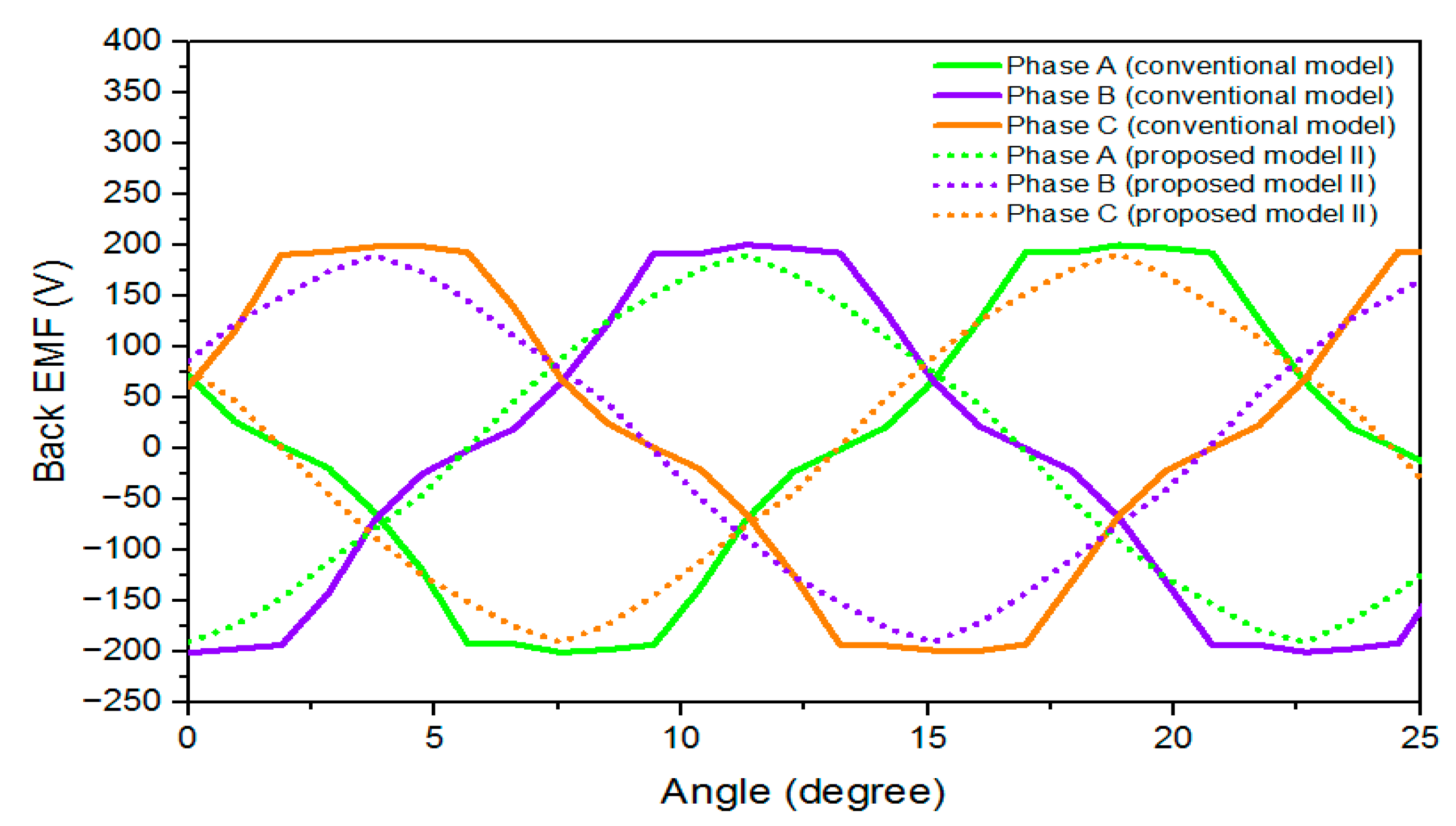
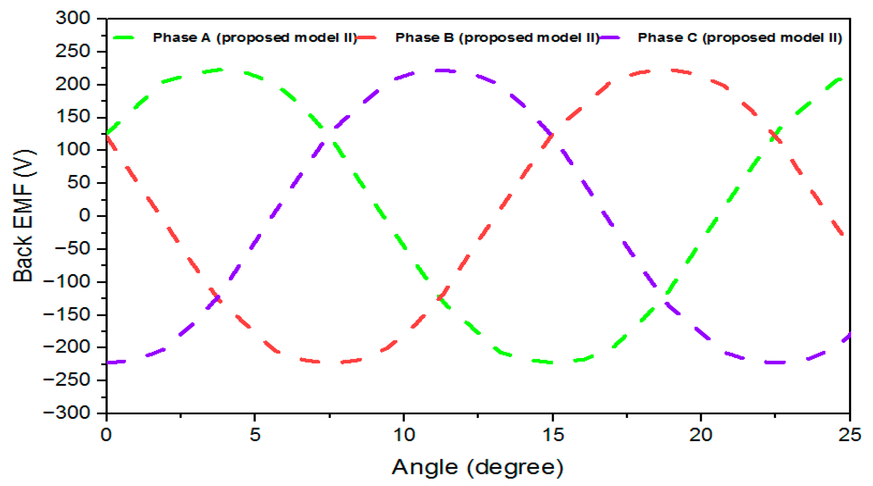
Air-Gap Flux Density, PM Flux Linkage, Back EMF, Cogging Torque and Output Torque
4. Conclusions
Author Contributions
Funding
Data Availability Statement
Acknowledgments
Conflicts of Interest
References
- Kimiabeigi, M.; Widmer, J.D.; Long, R.; Gao, Y.; Goss, J.; Martin, R.; Lisle, T.; Vizan, J.M.S.; Michaelides, A.; Mecrow, B. High-Performance Low-Cost Electric Motor for Electric Vehicles Using Ferrite Magnets. IEEE Trans. Ind. Electron. 2015, 63, 113–122. [Google Scholar] [CrossRef]
- Chen, Y.; Pillay, P.; Khan, A. PM wind generator topologies. IEEE Trans. Ind. Appl. 2005, 41, 1619–1626. [Google Scholar] [CrossRef]
- Li, Y.; Yang, H.; Lin, H.; Fang, S.; Wang, W. A Novel Magnet-Axis-Shifted Hybrid Permanent Magnet Machine for Electric Vehicle Applications. Energies 2019, 12, 641. [Google Scholar] [CrossRef]
- Ismagilov, F.R.; Papini, L.; Vavilov, V.E.; Gusakov, D.V. Design and Performance of a High-Speed Permanent Magnet Generator with Amorphous Alloy Magnetic Core for Aerospace Applications. IEEE Trans. Ind. Electron. 2020, 67, 1750–1758. [Google Scholar] [CrossRef]
- Kim, S.; Cho, J.; Park, S.; Park, T. Characteristics comparison of a conventional and modified spoke-type ferrite magnet motor for traction drives of low-speed. IEEE Trans. Ind. Appl. 2013, 49, 2516–2523. [Google Scholar] [CrossRef]
- Du, Z.S.; Lipo, T.A. Design of an Improved Dual-Stator Ferrite Magnet Vernier Machine to Replace an Industrial Rare-Earth IPM Machine. IEEE Trans. Energy Convers. 2019, 34, 2062–2069. [Google Scholar] [CrossRef]
- Amin, S.; Khan, S.; Bukhari, S.S.H. A Comprehensive Review on Axial Flux Machines and Its Applications. In Proceedings of the 2nd International Conference on Computing, Mathematics & Engineering Technologies (iCoMET 2019), Sukkur, Pakistan, 30–31 January 2019; pp. 1–7. [Google Scholar] [CrossRef]
- Kwon, J.-W.; Lee, J.-H.; Zhao, W.; Kwon, B.-I. Flux-Switching Permanent Magnet Machine with Phase-Group Concentrated-Coil Windings and Cogging Torque Reduction Technique. Energies 2018, 11, 2758. [Google Scholar] [CrossRef]
- Baig, M.A.; Ikram, J.; Iftikhar, A.; Bukhari, S.S.H.; Khan, N.; Ro, J.-S. Minimization of Cogging Torque in Axial Field Flux Switching Machine Using Arc Shaped Triangular Magnets. IEEE Access 2020, 8, 227193–227201. [Google Scholar] [CrossRef]
- Di Gerlando, A.; Foglia, G.; Iacchetti, M.F.; Perini, R. Axial flux PM machines with concentrated armature windings: Design analysis and test validation of wind energy generators. IEEE Trans. Ind. Electron. 2010, 58, 3795–3805. [Google Scholar] [CrossRef]
- Ali, R.; Amjadullah; Ali, S.; Ullah, H. Cogging-Torque Reduction Techniques in Axial Flux Permanent Magnet Machine. Int. J. Eng. Work. 2021, 8, 262–266. [Google Scholar] [CrossRef]
- Wang, X.; Sun, X.; Gao, P. Study on the effects of rotor-step skewing on the vibration and noise of a PMSM for electric vehicles. IET Electr. Power Appl. 2020, 14, 131–138. [Google Scholar] [CrossRef]
- Zhao, W.; Lipo, T.A.; Kwon, B.-I. Dual-stator Two-phase Permanent Magnet Machines with Phase-group Concentrated-coil Windings for Torque Enhancement. IEEE Trans. Magn. 2015, 51, 8112404. [Google Scholar] [CrossRef]
- Zhao, W.; Chen, D.; Lipo, T.A.; Kwon, B.-I. Dual Airgap Stator- and Rotor-Permanent Magnet Machines With Spoke-Type Configurations Using Phase-Group Concentrated Coil Windings. IEEE Trans. Ind. Appl. 2017, 53, 3327–3335. [Google Scholar] [CrossRef]
- Ying, H.; Zhang, Z.; Gong, J.; Huang, S.; Ding, X. Application for Step-skewing of Rotor of IPM Motors Used in EV. World Electr. Veh. J. 2011, 4, 532–536. [Google Scholar] [CrossRef]
- Zhao, W.; Lipo, T.A.; Kwon, B.-I. Design and analysis of a novel dual stator axial flux spoke-type ferrite permanent magnet machine. In Proceedings of the IECON 2013—39th Annual Conference of the IEEE Industrial Electronics Society, Vienna, Austria, 10–13 November 2013; pp. 2714–2719. [Google Scholar] [CrossRef]
- Zhao, W.; Lipo, T.A.; Kwon, B.-I. Torque Pulsation Minimization in Spoke-type Interior Permanent Magnet Motors With Skewing and Sinusoidal Permanent Magnet Configurations. IEEE Trans. Magn. 2015, 51, 8110804. [Google Scholar] [CrossRef]
- Li, Y.; Yang, H.; Lin, H.; Lyu, S.; Pan, Z. Comparative Study of Stator-Consequent-Pole Permanent Magnet Machines With Different Stator-Slot Configurations. IEEE Trans. Magn. 2019, 55, 8106308. [Google Scholar] [CrossRef]
- Aydin, M.; Gulec, M. Reduction of Cogging Torque in Double-Rotor Axial-Flux Permanent-Magnet Disk Motors: A Review of Cost-Effective Magnet-Skewing Techniques With Experimental Verification. IEEE Trans. Ind. Electron. 2014, 61, 5025–5034. [Google Scholar] [CrossRef]
- Gundogdu, T.; Komurgoz, G. Design of Permanent Magnet Machines with Different Rotor Type. In Internation General of Electrical and Computer Engineering World Academy of Science, Engineering and Technology. Int. J. Electr. Comput. Eng. 2010, 4, 10. [Google Scholar]
- Ge, X.; Zhu, Z. Optimal Step-Skew Methods for Cogging Torque Reduction Accounting for Three-Dimensional Effect of Interior Permanent Magnet Machines. IEEE Trans. Energy Convers. 2017, 32, 222–232. [Google Scholar] [CrossRef]
- Sikder, C.; Husain, I.; Ouyang, W. Cogging Torque Reduction in Flux-Switching Permanent-Magnet Machines by Rotor Pole Shaping. IEEE Trans. Ind. Appl. 2015, 51, 3609–3619. [Google Scholar] [CrossRef]
- Kim, S.-A.; Choi, G.-D.; Lee, J.; Cho, Y.-H. Optimal rotor shape design of 3-step skew spoke type BLAC motor to reducing cogging torque. Int. J. Appl. Electromagn. Mech. 2016, 51, S135–S145. [Google Scholar] [CrossRef]
- Blum, J.; Merwerth, J.; Herzog, H.-G. Investigation of the segment order in step-skewed synchronous machines on noise and vibration. In Proceedings of the 2014 4th International Electric Drives Production Conference (EDPC), Nuremberg, Germany, 30 September–1 October 2014. [Google Scholar] [CrossRef]


| Items | Symbols | Unit | Value |
|---|---|---|---|
| Number of stator slots | Q | - | 30 |
| Number of magnet poles | 2P | - | 32 |
| Stator/rotor outer diameter | Do | mm | 300 |
| Stator/rotor inner diameter | Di | mm | 174 |
| Total axial length | Ls | mm | 72 |
| Magnet span | Mw | degree | 11.25 |
| Magnet skew (Trap) | ά | degree | 5.625 |
| Magnet skew (Step) | ά | degree | 1.40625 |
| Air gap | g | mm | 1.0 |
| Stator tooth height | ht | mm | 19 |
| Stator yoke height | hy | mm | 5 |
| Rotor/PM height | hr | mm | 22 |
| Length of the Magnet | Lm | mm | 63 |
| Number of turns per coil | Nc | - | 36 |
| Connection | Y | - | Wye |
| Remanence of ferrite PM | Br | T | 0.43 |
| No of slots/phase belt | m | - | 2 |
| Coil spacing of different phase belt (conventional) | 1 | elec degree | 88 |
| Coil spacing of different phase belt (proposed) | 2 | elec degree | 32 |
| Distribution factor for conventional sequence | degree | 0.7192 | |
| Distribution factor for proposed sequence | degree | 0.9613 | |
| Rotor | - | - | 50H470 |
| Stator | - | - | 50H470 |
| Magnet | - | - | Ferrite |
| Coil | - | - | Copper |
| Item | Units | Conventional Model (DSAFSPM) Machine | Proposed Model I (DSAFSPM) Machine | Proposed Model II (DSAFSPM) Machine |
|---|---|---|---|---|
| Cogging torque (peak to peak) | Nm | 20 | 3.7 | 5 |
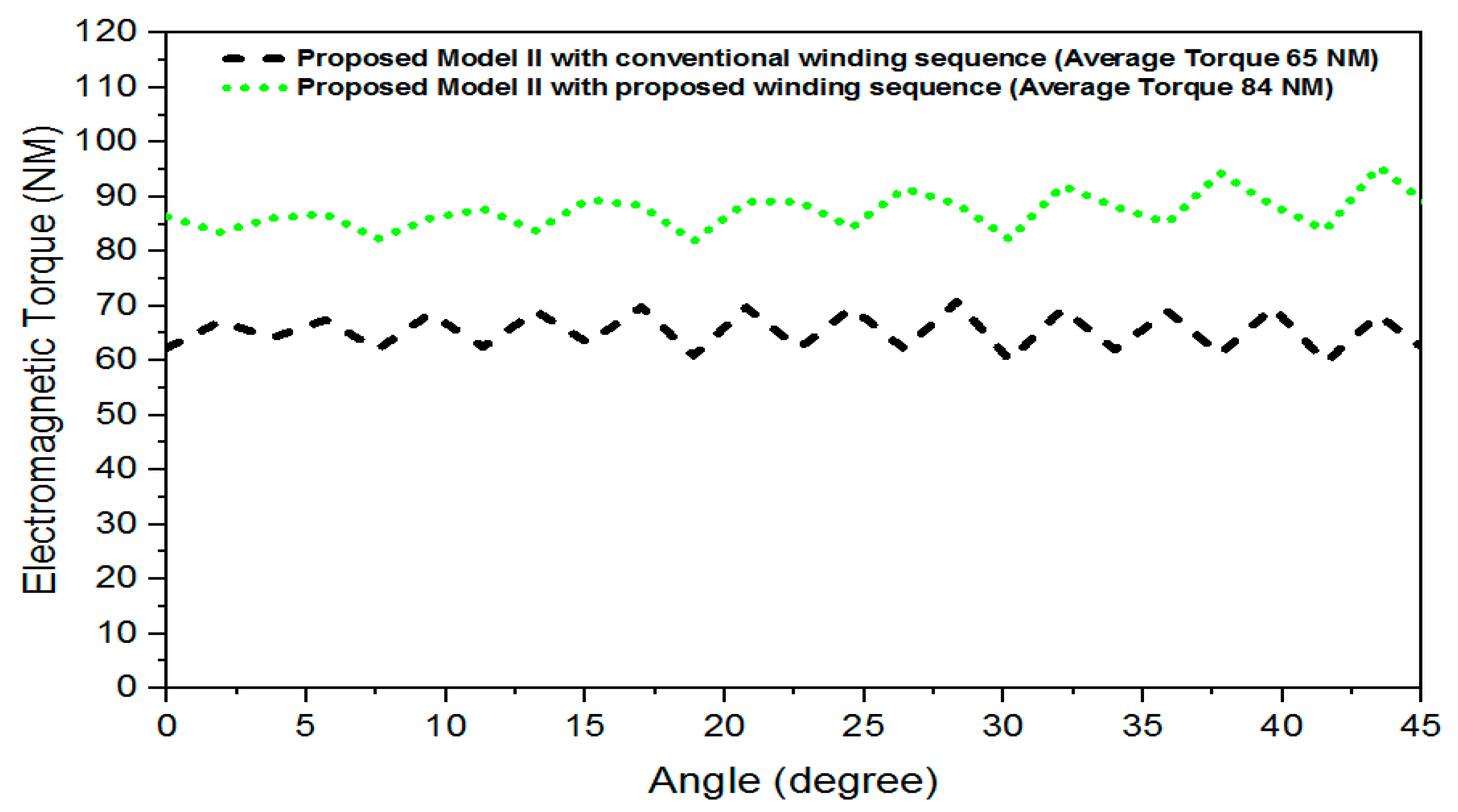
| Output torque (AVG) | Nm | 53.3 | 61.3 | 65 |
| Torque ripple factor | % | 41.6 | 16.3 | 16.9 |
| Phase back EMF (RMS) | V | 138.50 | 132.46 | 124.09 |
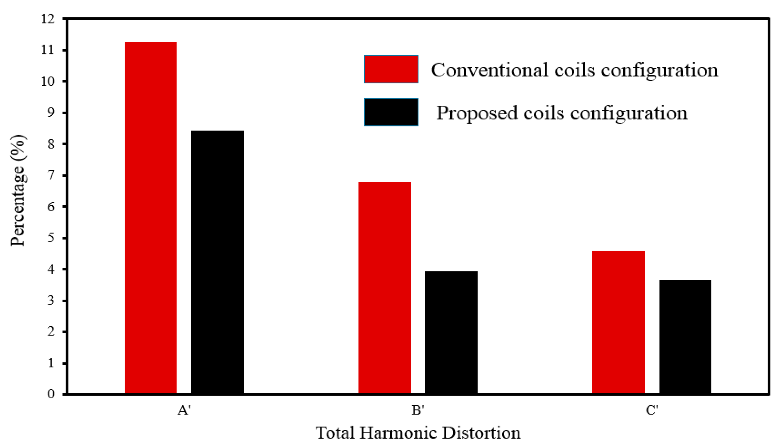
| VTHD | % | 11.2514 | 6.7869 | 4.6050 |
| Bg | T | 0.8295 | 0.7424 | 0.7849 |
| Copper loss | W | 125.5 | 125.5 | 125.5 |
| Iron loss | W | 58 | 41 | 41 |
| Efficiency | % | 93.6 | 94.8 | 95.1 |
| Item | Units | Conventional Model (DSAFSPM) Machine | Proposed Model I (DSAFSPM) Machine | Proposed Model II (DSAFSPM) Machine |
|---|---|---|---|---|
| Cogging torque (peak to peak) | Nm | 20 | 3.7 | 5 |
| Output torque (AVG) | Nm | 94 | 82 | 84 |
| Torque ripple factor | % | 16.5 | 6 | 16.5 |
| Phase back EMF (RMS) | V | 182.60 | 162.02 | 162.86 |
| VTHD | % | 8.4260 | 3.9371 | 3.6695 |
| Copper loss | W | 125.5 | 125.5 | 125.5 |
| Iron loss | W | 58 | 41 | 41 |
| Efficiency | % | 96.2 | 96.1 | 96.2 |
Publisher’s Note: MDPI stays neutral with regard to jurisdictional claims in published maps and institutional affiliations. |
© 2022 by the authors. Licensee MDPI, Basel, Switzerland. This article is an open access article distributed under the terms and conditions of the Creative Commons Attribution (CC BY) license (https://creativecommons.org/licenses/by/4.0/).
Share and Cite
Zakir, M.R.; Ikram, J.; Shah, S.I.; Bukhari, S.S.H.; Ali, S.; Marignetti, F. Performance Improvement of Axial Flux Permanent Magnet Machine with Phase Group Concentrated Coil Winding. Energies 2022, 15, 7337. https://doi.org/10.3390/en15197337
Zakir MR, Ikram J, Shah SI, Bukhari SSH, Ali S, Marignetti F. Performance Improvement of Axial Flux Permanent Magnet Machine with Phase Group Concentrated Coil Winding. Energies. 2022; 15(19):7337. https://doi.org/10.3390/en15197337
Chicago/Turabian StyleZakir, Muhammad Ramiz, Junaid Ikram, Saleem Iqbal Shah, Syed Sabir Hussain Bukhari, Salman Ali, and Fabrizio Marignetti. 2022. "Performance Improvement of Axial Flux Permanent Magnet Machine with Phase Group Concentrated Coil Winding" Energies 15, no. 19: 7337. https://doi.org/10.3390/en15197337
APA StyleZakir, M. R., Ikram, J., Shah, S. I., Bukhari, S. S. H., Ali, S., & Marignetti, F. (2022). Performance Improvement of Axial Flux Permanent Magnet Machine with Phase Group Concentrated Coil Winding. Energies, 15(19), 7337. https://doi.org/10.3390/en15197337