1. Introduction
Air-Cooled Exchangers (ACEs) are devices based on a gas-to-liquid heat transfer process. On the inner side of the tubes, a working fluid flows, while on the outer side atmospheric air appears. This type of system is called an active or mixed heat transfer technique [
1] because fluid or air flow must be caused by forced devices such as a pump or fan. If the working medium inside the tubes is water, these devices are also called dry-coolers [
2]. In the standard technical solution, the volumetric flow of air surrounding the outer surface of the heat exchange is forced by fans, usually with an axial air flow. Air then flows transversely to the tubes. There is also another solution; air flow through the heat exchanger can also be caused by thermal gravitational convection, that is, it can be induced due to the density difference that results from the inhomogeneous temperature distribution in the gravitational field [
3]. The use of them under conditions of natural convection seems attractive in the context of reducing the operating cost and time of fans. ACEs are used wherever it is necessary to dissipate the heat generated, for example, during technological processes or air-conditioning systems. The thermal resistance on the air side under free convection conditions is higher than in the case of forced convection [
4]. However, as the ambient air temperature decreases, it is possible to partially reduce the power used by the fan until the instantaneous cooling demand is satisfied with the device off. One way to increase the thermal efficiency of an ACE under natural convection conditions is to increase the external flow of air applying the height of the “housing” above the heat exchanger, that is, to take advantage of the so-called chimney effect.
Most of the work available in the literature covers the experimental determination of the heat-transfer coefficient under free convection conditions for single smooth tubes and individual finned tubes. For a bundle of smooth tubes, Bejan et al. [
5] experimentally and numerically investigated the effect of the spacing between pipes placed horizontally in a fixed volume on total heat transfer under conditions of laminar free convection between the system and the surrounding environment. They proposed a correlation for optimal pipe spacing in terms of heat flux.
Smooth pipe-made gas–liquid heat exchangers are rarely used in thermal engineering. This is due to the fact that the convective thermal resistance on the gas side is much higher than on the liquid side [
6]. There are many methods to increase local convective heat-transfer coefficients. One method is to add an elongated surface, which leads to an increase in the active area of heat transfer. As an elongated surface, wavy, spiral, louvered, plain, and slit fins are most commonly used [
7]. In addition, modifications are made to the shape of the active surface. These elements in the literature are called vortex generators [
8]. They consist of placing additional elements on the finned surface, causing the adhesion layer of the fluid to break the fluid layer near the wall [
9]. Active methods are also employed to increase the local heat-transfer coefficient. The effect of thermal breakage of the boundary layer on the heat transfer process was studied numerically and experimentally by Błasiak et al. [
10,
11,
12] This effect is achieved by moving blades called scrapers.
Kayansayan in [
13] experimentally investigated the effect of three physical parameters on the characteristics of free convection in a continuous thick horizontal isothermal circular finned pipe. In the experiment, the parameters of the finned pipe were modified, such as the distance between the fins, the diameter of the pipe, and the temperature difference between the surface of the solid element and the fluid. Depending on the temperature difference, the ratio of fin spacing to the outer diameter of the tube ranged from 0.25 to 0.50, and above and below this value there was a decrease in the heat penetration rate.
On the contrary, Hahne et al. in [
14] studied the effect of the diameter of the fin on the average heat-transfer coefficient of the air side and the temperature distribution on the surface of the fin under free convection conditions. The authors show that the average heat-transfer coefficient depends on the height of the fins, with higher values obtained for a fin with a smaller diameter. Note that the value of the fin pitch was constant at 8 mm. Yildiz et al. [
15] studied not only the height of the 1 mm thick fin pitch but also how the spacing between the fins affects free convection. The diameter of the fin ranged from 35 to 125 mm, while the spacing of the fin ranged from 3.6 to 31.7 mm. The outer diameter of the tube was 24.9 mm. The results indicate that for practical applications, the optimal fin spacing should be taken as 8 mm in the fin-diameter range tested and for base temperature differences of 50 to 150 °C.
One of the few articles that deals with the study of heat transfer from a bundle of finned tubes to air under free convection conditions was conducted by Katsuki et al. [
16]. They proposed a heat exchanger based on 25.4 mm diameter tubes with circular fins and a thickness of 0.8 mm and 58.4 mm in diameter that operate only under free convection conditions. The temperature between the finned surface and the surrounding air ranged from 24 to 50 °C. The pipes were placed in a chimney one meter high, vertically above each other on one axis. According to the authors, the spacing of the finned pipes in the vertical direction should be equal to five diameters of the pipes, so the intensity of the heat transfer will reach the highest value . Furthermore, the average heat-transfer coefficient for a bundle of pipes was 1.4 times higher than for a single pipe. Unger et al. [
17], in their work, investigated how the average heat-transfer coefficient under free convection conditions evolves for a two- and three-row heat exchanger placed in a chimney of 6.5 m in height. The study was carried out for three different types of fins, that is, circular plain fins; circular integrated pin-fins, and serrated integrated pin-fins. The two-row exchanger had a better than average heat penetration coefficient than the three-row exchanger. The heat exchanger with serrated integrated pin-fins had the highest air-side heat-transfer coefficient in the three- and two-row configurations. This was due to the fact that the used exchanger had the lowest coefficient of resistance to air flow.
Individually finned tubes are characterised by higher strength, while flat-fin heat exchangers are less expensive per unit of heat-transfer surface area [
2]. Heat exchangers with flat fins are widely used in heating, ventilation, and air-conditioning (HVAC) systems. To the authors’ knowledge, there are no studies in the literature on the thermal performance of ACEs with flat fins under free convection conditions. Most of the available work focusses on studies of heat exchangers made of individually finned tube packages. Heat exchangers with flat fins differ significantly in design from heat exchangers composed of individually finned tubes, and consequently it is difficult to find relations for the Nusselt number as a function of the Rayleigh number for the geometrical configurations studied in this work. It should be noted that there is a lack of studies in the literature on the influence of the casing height on the thermal performance of heat exchangers and the formation of the so-called chimney effect on the thermal performance of ACEs with flat fins under natural convection conditions.
In the present study, the authors tested the effectiveness of increasing the heat-transfer coefficient using the chimney effect. In addition, the effect of the height of the chimney on the average heat flux and, next, on the average heat-transfer coefficient was investigated. Research was carried out for two selected heat exchangers with flat wavy fins. The most important differences in the heat exchanger structure were: the number of pipe rows, their diameter and spacing, and the height of the fins and their spacing. The exchangers had a similar front area and a similar external heat-exchange surface. The Rayleigh number for the cases studied ranged from 25 to 180.
4. Methodology of Analysis
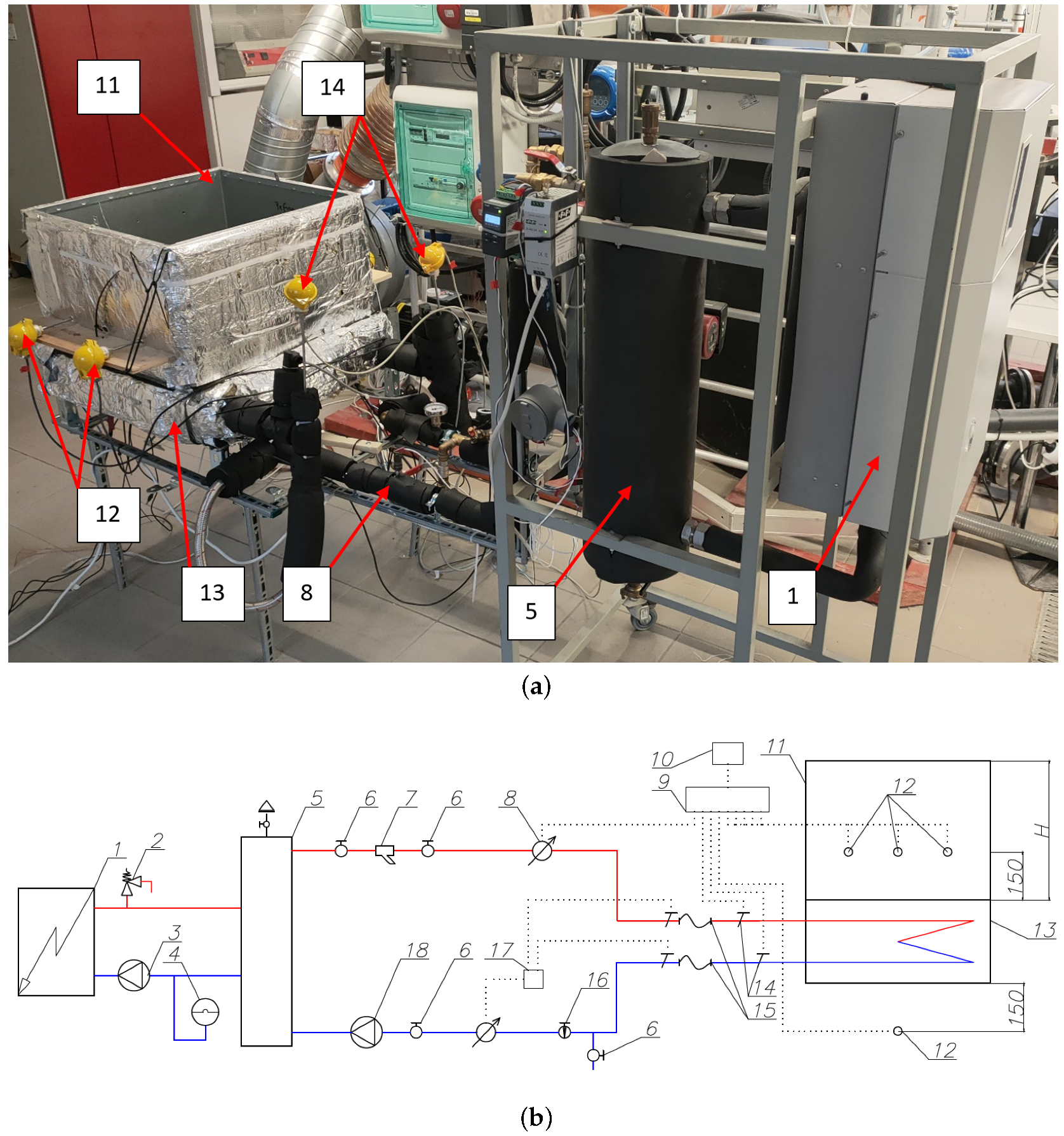
As a result of the use of thermal insulation on the external structural elements of the exchanger, it was assumed that the entire value of the heat taken from the water is returned to the surrounding air through the extended surface. Then, the heat balance of the exchanger can be described by relation (
5).
where
is the heat flux taken in by air;
is the heat flux given by water,
determines the volume flow rate of the water; the density of the water
,
is the average specific heat of the water; and
indicates the difference between the temperature of the water at the inlet and the outlet.
The heat flux
q was determined in relation to the external heat-transfer surface on the basis of the following relationship:
Getting a measurement of the temperature of the finned surface for the determination of local heat-transfer coefficients in finned heat exchangers is very difficult as the measurement should be non-invasive and not cause disturbances in the velocity profile of the flowing medium. However, it is not a problem to experimentally determine the overall thermal conductance of the exchanger under study. This coefficient is given by the following equation:
where
is referred to as the overall thermal conductance, F is the log-mean temperature difference correction factor for crossflow arrangement [
2], and
determines the mean logarithmic temperature difference of the factors in the heat exchanger.
The mean logarithmic temperature difference was determined from the following equation:
where
and
are the inlet and outlet water temperatures of the exchanger, respectively, while
and
are the air temperature before and after the exchanger, respectively.
A steady-state heat transfer proceeds as follows: convection from the hot fluid to the wall, conduction through the wall, and convection from the wall to the cold fluid [
2]. The total thermal resistance of the exchangers studied can be determined by the following equation:
where
determines the extended surface efficiency determined from Equation (
13),
describes the average coefficient of convective heat transfer on the air side,
the heat-transfer coefficient of the pipe material,
determines the length of the pipe in a row, and
defines the average heat-transfer coefficient on the water side.
Uniform water flow was assumed in each circuit of the exchanger. The Nusselt number on the water side was determined on the basis of the correlation developed by Gnielinski [
21]. This relationship was formulated for the Reynolds number
in the range of 2300 to 5 × 10
6 and the Prandtl number
from 0.5 to 2000. The characteristic dimension of the Reynolds number is the inner diameter of the pipe.
Here, the friction coefficient
f for the transition flow (
) is given by the following formula [
22]:
On the other hand, for turbulent flow (
), the coefficient
f is given by the following equation [
22].
The temperature efficiency of the surface developed on the air side was determined on the basis of Schmidt’s approximation [
23].
where
is the surface area of the fin and
is the fin efficiency.
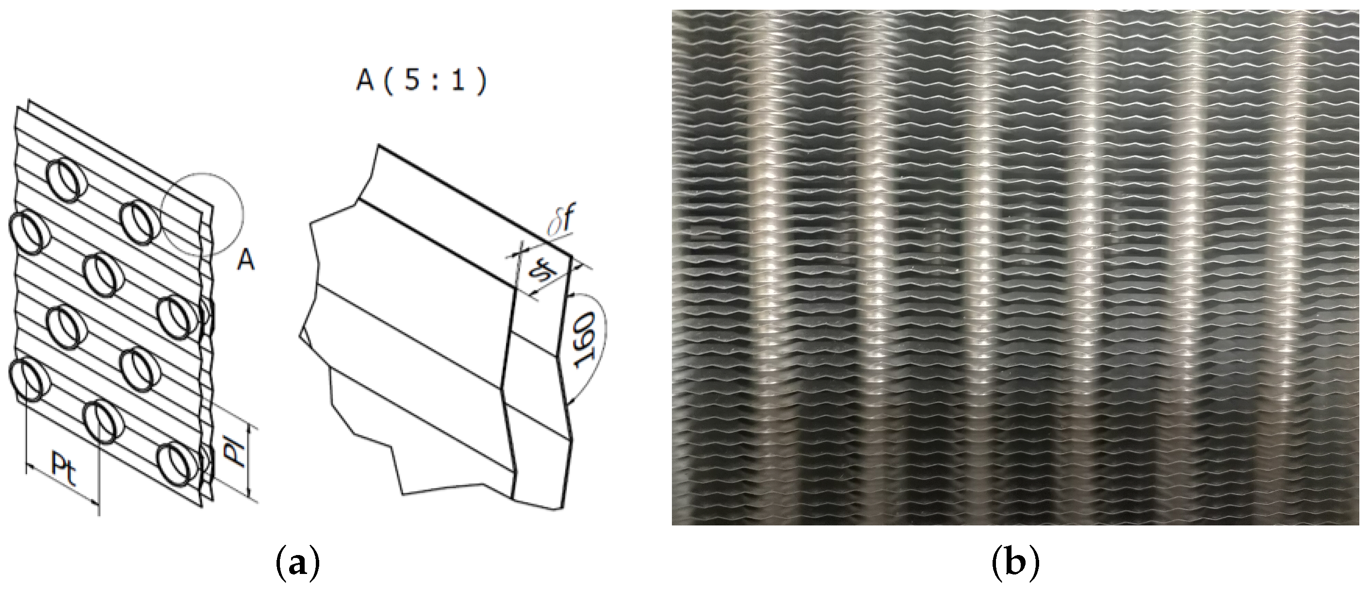
where
In the above relationships, is to determine the thermal conductivity of the fin material, the thickness of the fins, r is the inner diameter of the base of the fins, and Pl and Pt are the longitudinal and transverse pitch of the tube, respectively.
The value of the heat-transfer coefficient for the air side is presented in dimensionless form by means of the Nusselt number, Equation (
18), while the results will be parameterized by the Rayleigh number, Equation (
19).
where
is the average thermal conductivity coefficient of the air and
is the characteristic dimension, Equation (
20).
where
determines the coefficient of volumetric thermal expansion,
g is the value of gravitational acceleration,
the average density of the air,
the difference between the average surface temperature of the exchanger and the temperature of the surrounding air,
the average specific heat of the air, and
the average dynamic viscosity of the air.
The characteristic dimension of dimensionless numbers is the equivalent hydraulic diameter
, calculated from the following relation [
24].
where
is the cross-sectional area of the flow and
is the total area of heat transfer.
The parameters of water and air, such as density , viscosity , and thermal conductivity coefficient , are determined for the average temperatures after the steady state is reached.
5. Results and Discussion
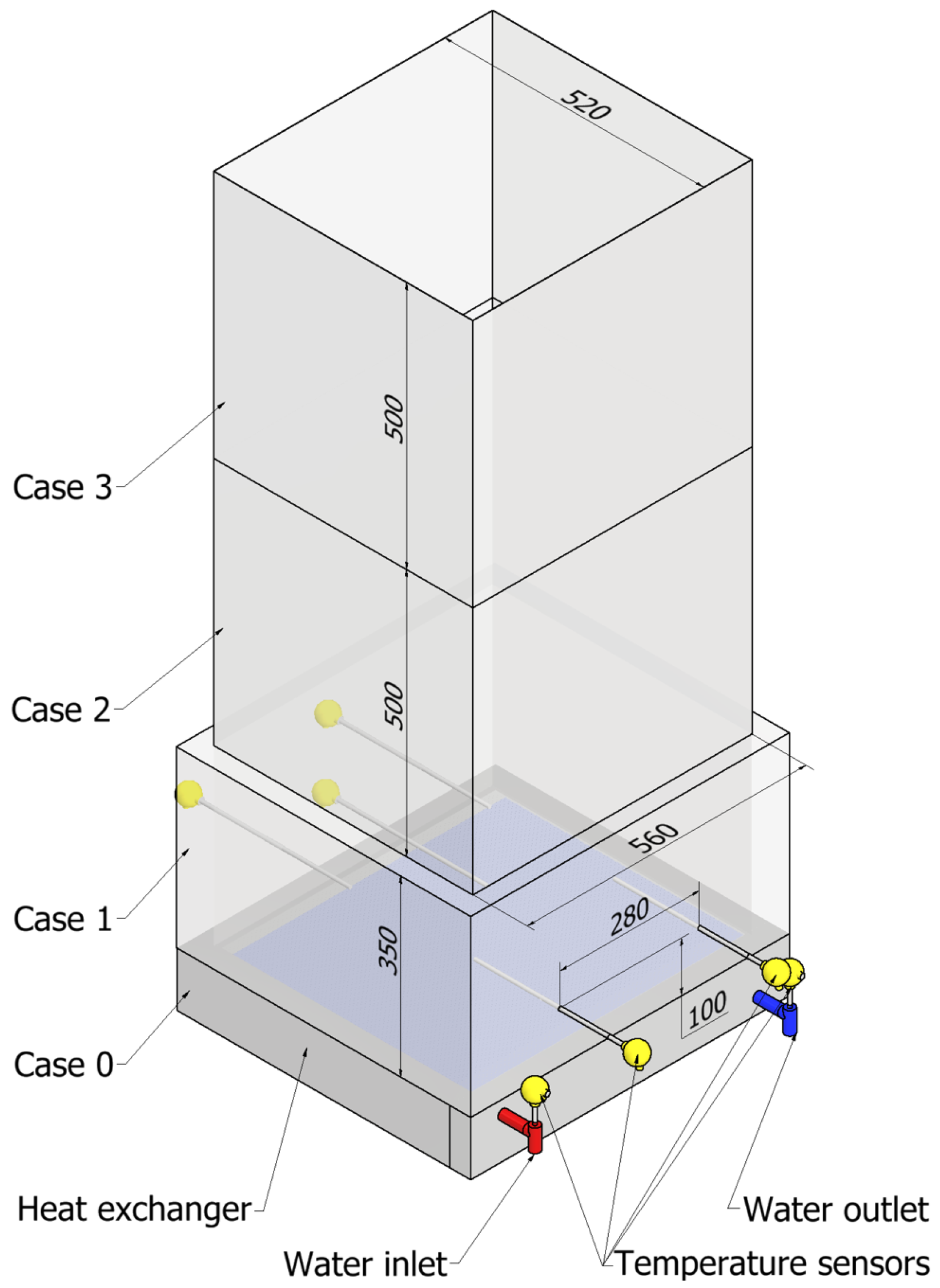
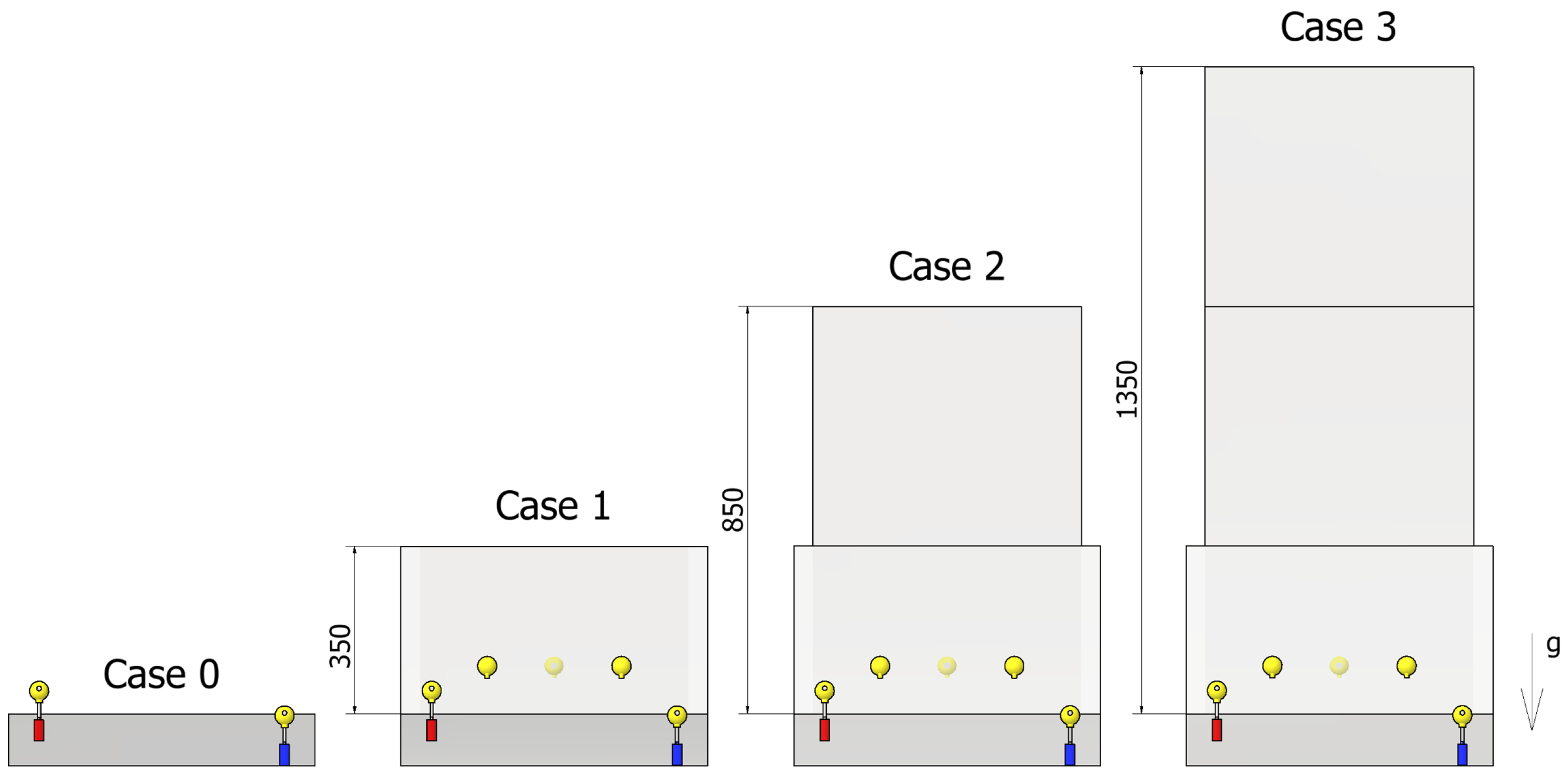
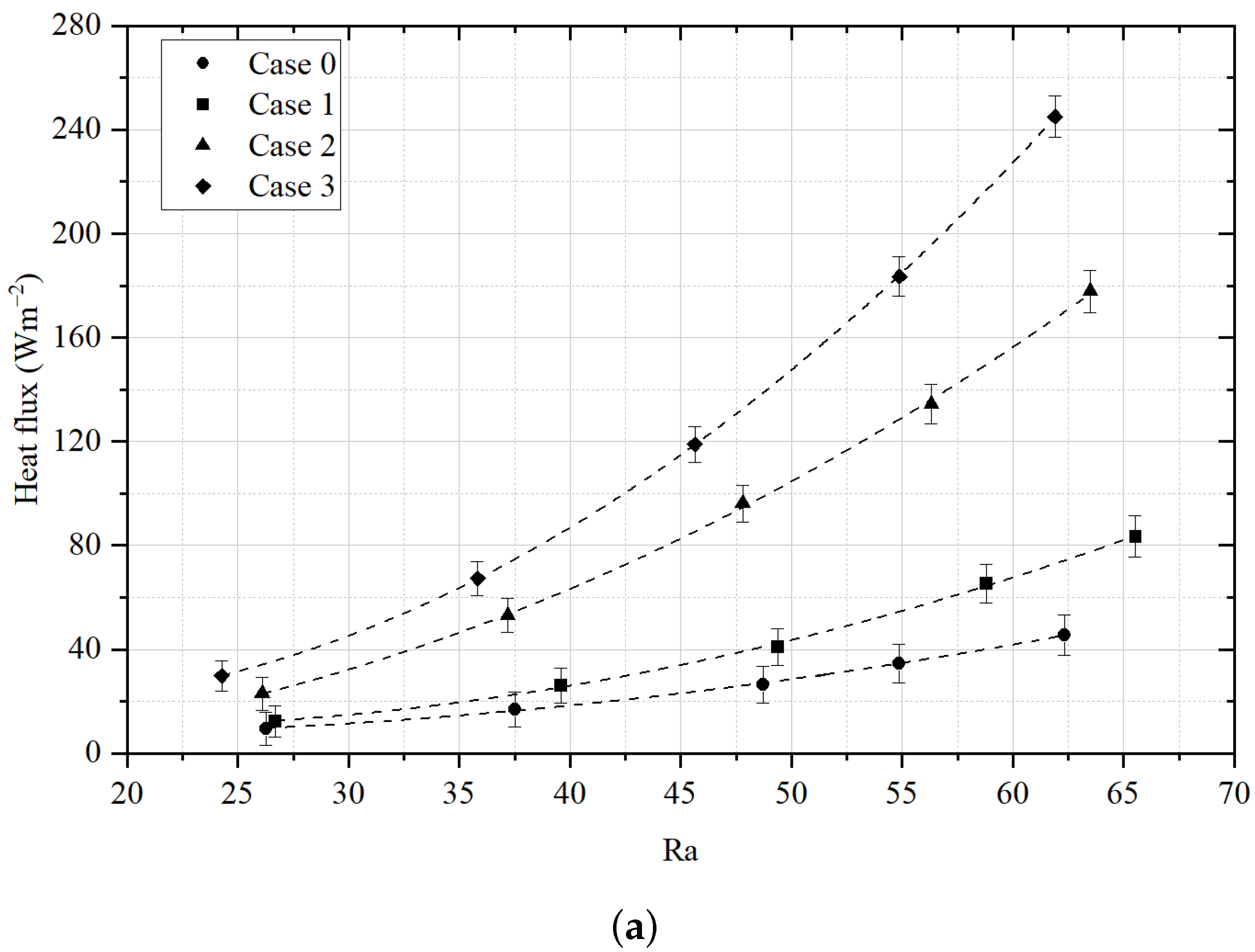
In this paper, the effect of chimney height on the average heat-flux density was experimentally investigated. The results are presented on the basis of dimensionless criterion numbers. Research was carried out on two air-to-water heat exchangers with flat wavy fins, named heat exchangers no. 1 and no. 2, respectively. The first campaign investigated how the heat output of the exchanger changes without a chimney installed (Case 0) for feedwater temperatures in the range of 40 to 80 °C. Then, for similar feedwater temperatures, tests were carried out for an enclosure with heights of 350 mm (Case 1), 850 mm (Case 2), and 1350 mm (Case 3).
Figure 5 show how the heat-flux density for the variants tested changes as a function of the Rayleigh number. The measurement uncertainties and polynomial regression curves are also plotted in the graphs. The heat-flux density dissipated by the exchanger increases as the Rayleigh number increases. Adding an enclosure/chimney to the exchanger results in a significant increase in the power of the exchanger. The difference in heat-flux density between the cases increases as the Rayleigh number increases.
The increase in heat-flux density with an increase in the Rayleigh number, as well as the height of the chimney, is due to growth in the difference in air pressure at the inlet and outlet of the heat exchanger. This difference increases as the density difference and the active height of the chimney increase and can be described by relation (
21). As the pressure difference increases, the air flow rate on the extended surface also increases:
where
is the local resistance coefficient,
the average air density, and
the air flow velocity through the exchanger.
The heat exchanger no. 2 with a larger fin spacing is characterised by a lower resistance to air flow, which makes it achieve higher thermal efficiency in the range of tested parameters than the heat exchanger no. 1, which has approximately 47% smaller spacing between the fins.
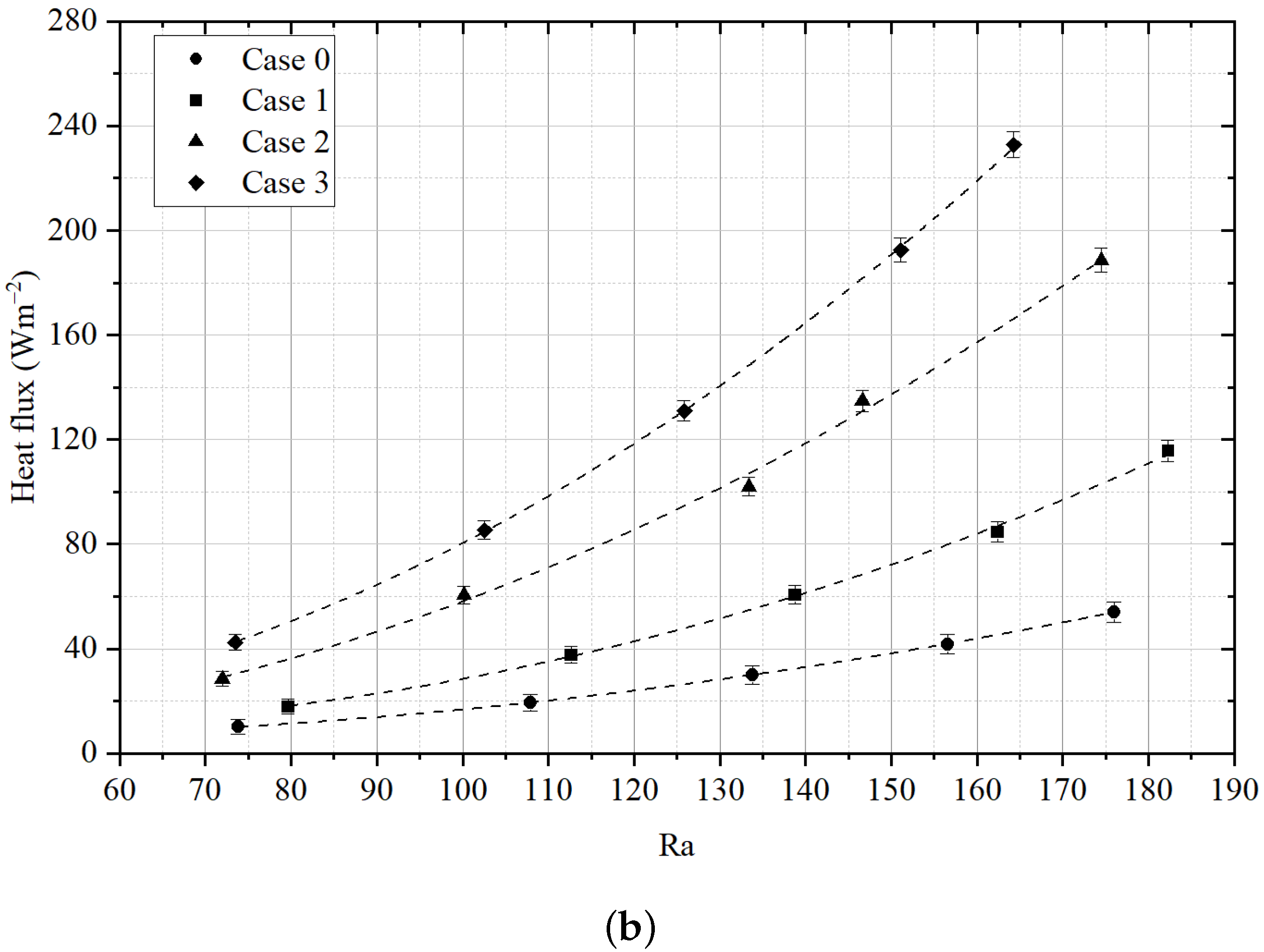
Figure 6a,b show how the average value of the air-side Nusselt number changes for the Rayleigh number ranges studied.
As can be observed in
Figure 6a,b, the average Nusselt number increases as the height of the chimney above the exchanger increases and the Rayleigh number increases. The exchanger without an enclosure (Case 0) has the lowest value of the Nusselt number. The highest increase in the Nusselt number with an increase in the Rayleigh number is observed for the case with a chimney height of 1350 mm (Case 3). The low thermal performance of the tested exchangers without a chimney (Case 0) is due to the fact that a significant part of the air infiltrates the unit from the side of the exchanger, receiving heat only from the front surface of the heat exchanger. The addition of a 350 mm-high casing (Case 1) reduces the inflow of air from the side, thus forcing air through the heat exchanger due to the vacuum created in the chimney space. The addition of additional casing heights (Case 2) and (Case 3) increases the volume flow rate of air that passes through the heat exchanger; there is then an increase in the air velocity between the fins, resulting in a significant increase in local heat transfer coefficients.
For heat exchanger no. 2 characterised by a chimney height of 1350 mm and a Rayleigh number in the range of 150 to 170, a decrease in the growth of the Nusselt number was observed. Interestingly, this situation is not noted for heat exchanger no. 1, see
Figure 6.
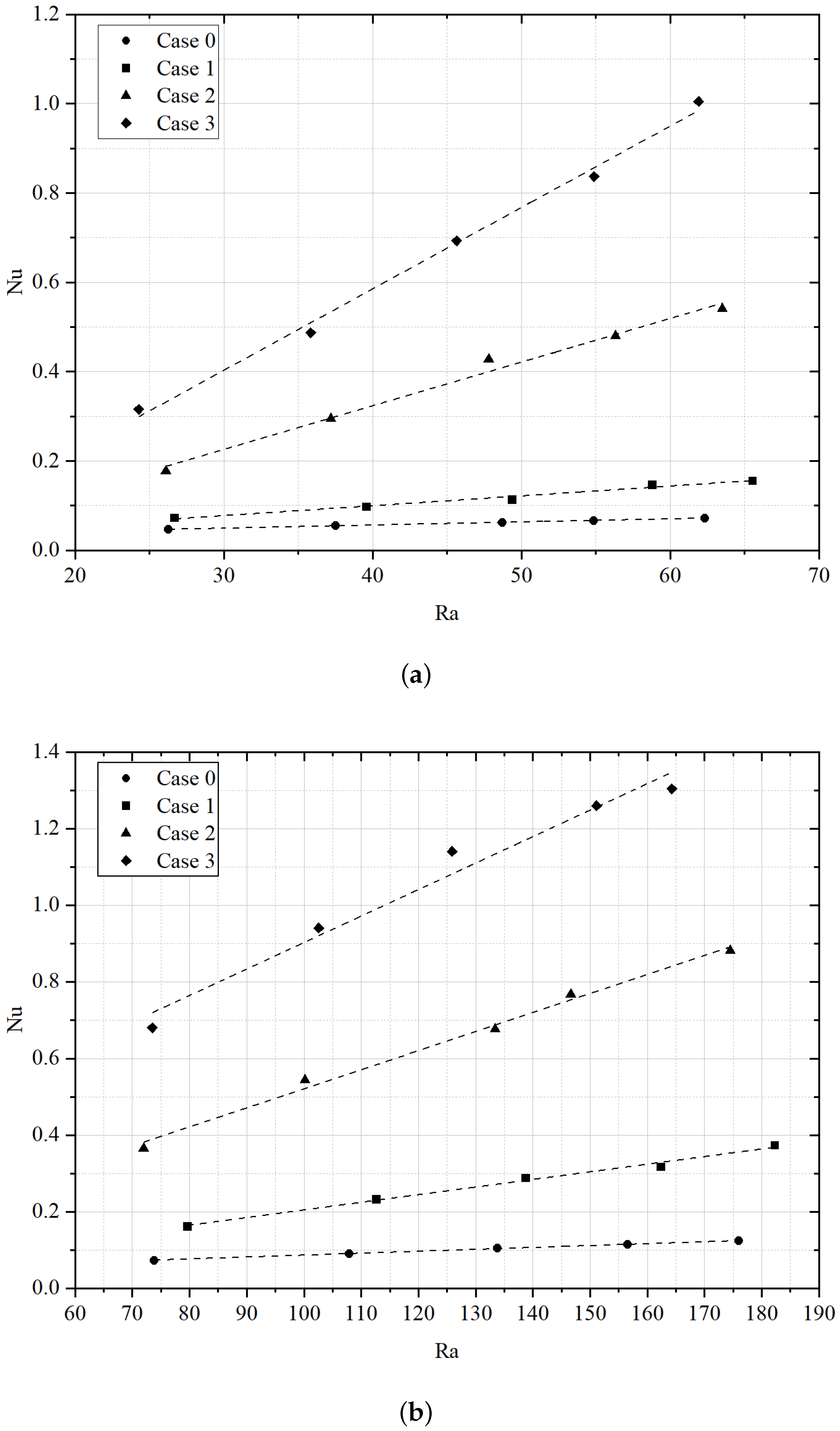
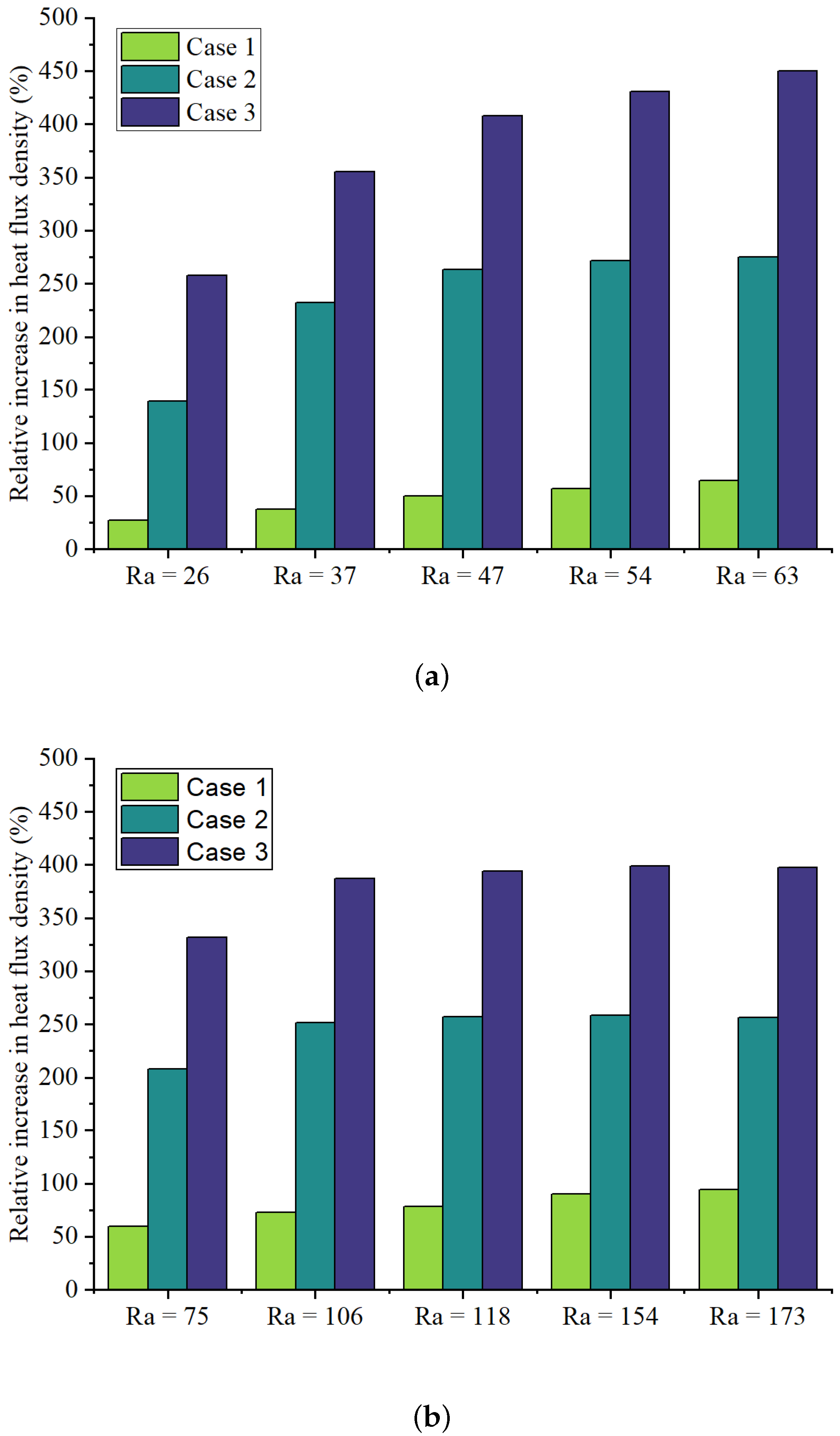
As can be pointed out, as the height of the chimney increases, the heat-flux density increases as well.
Figure 7 shows this process based on a dimensionless parameter called the relative increase in the heat-flux density,
, which is defined by the following relation:
where
is the heat-flux density for the case of a heat exchanger without an additional casing/chimney (Case 1), while
q is the heat-flux density for the particular case under consideration.
The effect of chimney height on the increase in the specific heat output of exchanger no. 1 is shown in
Figure 7a. The observed increase in the average heat-flux density for a chimney height of 1350 mm (Case 3) averaged from 250 to 450% over the range of the Rayleigh numbers tested. For heat exchanger no. 2, the effect of chimney height on the increase in the heat-flux density is shown in
Figure 7b. In the range of the Rayleigh numbers studied, the observable increase in heat-flux density for a chimney height of 1350 mm (Case 3) ranged from 332 to 397%.
It can be seen in
Figure 7 that for exchanger no. 1, the increase in average heat-flux density is much greater than for exchanger no. 2 for the variant with a chimney height of 850 mm (Case 2) and 1350 mm (Case 3). The situation looks different for a variant with a chimney height of 350 mm (Case 1), in which case a larger increase is observed for exchanger no. 2.
6. Practical Significance
Air-cooled heat exchangers (ACEs) are used, among others, in the gas, petrochemical, and food industries. These units are used extensively to remove heat from the surroundings from condenser sections, for example, in compressor refrigeration units. ACEs are also applied in free-cooling ventilation and air-conditioning systems. Most often, the operating parameters of the unit are selected to ensure the required heat removal under the most unfavourable conditions, i.e., when the outside air temperature reaches the highest design values. As the temperature decreases, the power of the selected heat exchanger increases. In order to reduce the electricity operating consumption of ACEs, fans with variable speed control are often installed. Until the unit’s target outlet temperature is satisfied, the fan output is reduced until it stops completely, at which point free convection is the only mechanism for the heat transfer to the environment.
As the research presented in this paper shows, one way to increase the thermal performance of the heat exchangers tested, operating under free convection conditions, is to install an enclosure over them. With this technique, the airflow through the exchanger is further intensified, taking advantage of the resulting chimney effect. As shown in the research, the addition of 1.4 m of chimney allows the ACEs to operate for a significantly longer time with the fans switched off, thus reducing the electricity consumption of the fans. The studies show that this effect is obtained for heat exchangers with significantly different design parameters.


