Review

Keynote Review of Latest Advances in Thermoelectric Generation Materials, Devices, and Technologies 2022

1
NASA-Jet Propulsion Laboratory, California Institute of Technology, 4800 Oak Grove Drive, Pasadena, CA 91109, USA
2
International Center for Materials Nanoarchitectonics (WPI-MANA), National Institute for Materials Science (NIMS), Namiki 1-1, Tsukuba 305-0044, Japan
3
Graduate School of Pure and Applied Science, University of Tsukuba, 1-1-1 Tennodai, Tsukuba 305-8671, Japan
*
Authors to whom correspondence should be addressed.
Retired.
Energies 2022, 15(19), 7307; https://doi.org/10.3390/en15197307
Submission received: 26 July 2022 / Revised: 10 September 2022 / Accepted: 19 September 2022 / Published: 5 October 2022
(This article belongs to the Special Issue Advanced Thermoelectric Generation Technologies 2022)

Abstract

:
The last decade created tremendous advances in new and unique thermoelectric generation materials, devices, fabrication techniques, and technologies via various global research and development. This article seeks to elucidate and highlight some of these advances to lay foundations for future research work and advances. New advanced methods and demonstrations in TE device and material measurement, materials fabrication and composition advances, and device design and fabrication will be discussed. Other articles in this Special Issue present additional new research into materials fabrication and composition advances, including multi-dimensional additive manufacturing and advanced silicon germanium technologies. This article will discuss the most recent results and findings in thermoelectric system economics, including highlighting and quantifying the interrelationships between thermoelectric (TE) material costs, TE manufacturing costs and most importantly, often times dominating, the heat exchanger costs in overall TE system costs. We now have a methodology for quantifying the competing TE system cost-performance effects and impacts. Recent findings show that heat exchanger costs usually dominate overall TE system cost-performance tradeoffs, and it is extremely difficult to escape this condition in TE system design. In regard to material performance, novel or improved enhancement principles are being effectively implemented. Furthermore, in addition to further advancements in properties and module developments of relatively established champion materials such as skutterudites, several high performance ZT ≈≥ 2 new material systems such as GeTe, Mg3(Sb,Bi)2 have also been relatively recently unearthed and module applications also being considered. These recent advancements will also be covered in this review.

1. Introduction

One important aspect for sustainable future society and carbon neutral goals is to develop new viable technologies for energy saving [1]. Additionally, technologies are necessary which can dynamically harvest energy from surroundings to power the vast number of sensors and devices necessary for Internet of Things (IoT) applications [2]. Thermoelectric materials represent the solid-state conversion of waste heat to electricity and are promising to contribute to both goals [3,4,5,6,7,8,9,10,11,12,13,14]. To achieve these goals, it is vital to accelerate the development of both materials and devices. Namely, the thermoelectric performance, i.e., output power and conversion efficiency, of viable materials need to be enhanced. Likewise, the effective design, construction, and total thermal management of thermoelectric power generation devices also needs to be developed.
This review attempts to cover some of the most recent advancements in both of these important topics; thermoelectric materials and devices, which the authors are particularly familiar with, and hopes to give some guide and insight on promising directions for further efforts to bring thermoelectric power generation to mainstream fruition.

2. Advances in Thermoelectric Materials and Methods

2.1. Recent Advancements in Thermoelectric Property Enhancement Principles

Although thermoelectric modules and systems possess several distinct advantages being solid state devices, such as being compact, potentially integratable, silent vibration-free operation, being maintenance-free, etc., the conversion efficiency is still not particularly high. The higher the efficiency, the possible applicative usages can be expected to expand. Therefore, in addition to the module and system considerations which will be discussed later in this review, there is an imperative need to further enhance the performance of the materials.
The conversion efficiency of thermoelectric (TE) materials is a monotonically increasing function of the figure of merit, ZT. ZT = S2σT/κ, where S, σ, κ and T are the Seebeck coefficient, electrical conductivity, thermal conductivity, and the absolute temperature, respectively. The numerator of Z, S2σ, is called the power factor since it gives a measure of the thermoelectric power output. There have been various reviews up to now dealing with the various thermoelectric ZT enhancement principles [15,16,17,18,19]. Here, we will briefly summarize several of the enhancement principles which have been newly developed or improved recently.

2.1.1. Power Factor Enhancement

The Seebeck coefficient and electrical conductivity are typically in a tradeoff relationship, and so beyond the carrier concentration optimization it is necessary to find principles to enhance the Seebeck coefficient. Various band engineering methods have been proposed and effectively applied. The most straightforward one and widely used is by tuning the band gap via doping. For example, recently high power factors exceeding 10 mW/m/K2 which is several factors larger than Bi2Te3-type materials were obtained in full Heusler Fe2VAl-type materials via band gap tuning [20]. Such a very large power factor has also been obtained for the doped Half-Heusler FeNbSb [21]. Other band engineering principles have been proposed such as resonance doping, where the Seebeck coefficient is enhanced via the increased slope of the density of states near the Fermi level [22], and band convergence, where S is enhanced via band degeneracy [23,24]. Modifying the band structure is not always easy, and energy filtering has provided a more readily implemented enhancement effect although not so clear in design. Namely, in composite materials in some cases, low-energy carriers can be scattered by the potential barrier at a heterogeneous interface, so that high-energy carriers selectively pass through, and the Seebeck coefficient increases [25].
As mentioned above, research related to the above principles has been reviewed [16,17,18,19], and this review would like in particular to cover one renewed interest to utilize magnetism as a method for enhancing the power factor. As an intuitive image, one aspect to increase the Seebeck coefficient is by increasing the effective mass m* of carriers through interaction with magnetism. As background, the Seebeck coefficient can be expressed as the following equation in a simple SPB (single parabolic band) model,
S = 8 π 2 k B 2 3 e h 2 ( π 3 n ) 2 / 3 m * T
where n is the carrier concentration and in an inverse relation with S. The increase in effective mass and thereby the Seebeck coefficient via drag effects has been known for magnon drag resulting in a rise at low temperatures in some ferromagnetic metals at early times [26], and also phonon drag [27,28], likewise at relatively low temperatures. Recently, magnon drag has been proposed to be effective at higher temperatures near room temperature for such materials like CuFeS2 chalcopyrite [29] and Fe2VAl Heuslers [30] resulting in power factors above 1 mW/m/K2, for these materials composed of relatively light and abundant elements.
Such enhancement is shown recently to not just be limited to magnetically ordered systems, but it has also been demonstrated that utilizing magnetic interactions in the paramagnetic region, i.e., paramagnon drag, [31,32,33], has also been shown as an effective strategy for enhancing the Seebeck coefficient and overall power factor. One example as given in Figure 1 is the enhancement of the power factor of CuGeT2 via magnetic Mn ion doping [31]. A strong coupling between the magnetic ion and carriers was realized as evinced by the increase in effective mass. In further work, to remove any ambiguity from simultaneous carrier concentration variation, isoelectronic Cr substitutional doping into Bi2Te3, versus non-doping and same valence Ga doping. The Cr doping induces significant magnetic interaction, exhibiting ferromagnetism at around 220 K, and the power factor is almost doubled compared to the non-doped or non-magnetic element doped case [33].
Heremans and coworkers carried out a neutron diffraction study on the MnTe-based thermoelectric material. As shown in Figure 2, they observe the existence of paramagnons in the paramagnetic region. Additionally, as an important point, they also observe that the paramagnon lifetime is longer than the electron-magnon scattering time [32]. This indicates that the paramagnon is a viable entity to possess interaction with the charge carriers, resulting in possible enhancement of the Seebeck coefficient as has been proposed above.
In addition to magnon drag and paramagnon drag, spin fluctuation was also recently demonstrated to enhance the Seebeck coefficient in an itinerant ferromagnetic system [34] leading to relatively high power factors at room temperature. Namely, application of magnetic field was observed to depress the Seebeck coefficient. Experimentally the applicable magnetic field of 9 T only suppresses by a small margin, however, this is because of the small energy scale of the magnetic field, and the spin fluctuation effect can be considered to be suppressed only a little. The Seebeck coefficient for example at 400 K for the largest effect sample, was 1.5 times that of the extrapolated diffusion limit (Figure 3), so spin fluctuation may be contributing significantly to the Seebeck coefficient.
Doping with magnetic nanoparticles has also led to enhancement of ZT in skutterudites (SKDs) [35,36] and Bi2Te3-type materials [37,38], for example. Although the effects had initially mainly been discussed in terms of energy filtering, and thermal conductivity reduction, a magnetic effect such as described above, may also be contributing to the improvement.
The spin entropy in oxides for example with the mixed valency of Co have been indicated to enhance the Seebeck coefficient [39,40]. Mixed valency of Sm in SmB66 was considered to be the origin of the enhanced power factor compared to trivalent rare earth counterparts [41]. The spin entropy effect to enhance S has also been observed in some magnetic transition metal sulfides, illustrating that this is a general principle [42].
In regard to the above principles, utilizing magnetism in some cases can be relatively easily implemented, such as for the paramagnetic drag, via doping of magnetic ions [31,32,33]. However, a necessary condition is the strong interaction between the magnetic moment and electrical carrier. Power enhancement has been demonstrated for various material systems like SnTe, Bi2Te3-type materials, etc. [43,44,45,46]. Magnetic semiconductors with relatively high thermoelectric performance have also been newly unearthed [47]. The magnetism field is traditionally larger than the thermoelectric field and interdisciplinary efforts can be expected to lead to further development of high performance thermoelectric materials.
Besides the various principles given above for Seebeck coefficient enhancement, additional improvement of the electrical conductivity has also been attempted, beyond simple carrier concentration increase which decreases the Seebeck coefficient in a trade-off. Attempts to modify the grain boundaries to reduce the carrier scattering have yielded increases in the PF [48,49,50]. A couple of notable examples will be given below in Section 2.2.2. It has also been proposed that partially percolating metallic networks can lead to increased power factor for some composites [51,52].

2.1.2. Low Thermal Conductivity Principles

The potential intrinsic thermoelectric output power of a material is determined by the power factor, but possessing low thermal conductivity is critical for the temperature gradient to produce the thermopower, and therefore, for high efficiency. There are two approaches to achieve this, namely, first of all utilizing extrinsic principles such as nanostructuring to form in the materials, artificial structures which can selectively scatter phonons. Second is to start from a material which has built-in mechanisms for intrinsic low thermal conductivity.
There have been several early reports where nanostructuring was demonstrated to achieve high performance, such as utilizing inclusions [53] and precipitations [54] to enhance ZT of PbTe-based materials, and top-down methods such as utilizing ballmilling to enhance SiGe [55], for example. Up to now there have been myriad examples of ZT enhancement via nanostructuring for various thermoelectric materials. The understanding of how different nanostructures/defects affect the phonon scattering has also become quite refined [56,57]. Namely, the phonon frequency, ω, dependence of the phonon relaxation time τ for example of point defects, such as vacancies, interstitials, alloyed atoms is
τPD−1∝ω4
thereby effective to scatter high frequency phonons. Line defects, namely dislocations have
τLD−1ω1, τDC−1ω3
for dislocation strain fields, dislocation cores, respectively, thereby scattering mid-frequency phonons in particular.
Two dimensional defects, namely, grain boundaries have
τGB−1ω0
and thereby are effective to scatter low frequency phonons, while volume defects, such as nanoprecipitates and nanovoids have
τVD−1~ω0+ω4
thereby scattering phonons over a wide range. In this way, if a high degree of control over formation of such nanostructures/defects in a particular target material can be achieved, the phonon scattering can be better designed to realize higher performance.
In particular, for compounds like GeTe in which defects are easy to form, various control over the formation has been carried out to lead to high ZT~2. Several examples will be given below in Section 2.2.1.
In addition to such extrinsic effects, several recent observations for unearthing intrinsic low thermal conductivity materials are presented.
  • Example of utilizing materials informatics to find low thermal conductivity compounds
First of all, it should be stressed that the utilization of materials informatics and data mining, to try to find high performance thermoelectrics, not limited to the low thermal conductivity aspect, has become increasingly popular, with various results recently reported [58,59,60,61,62].
Here, we give one example that one of our groups has carried out to try to unearth new promising thermoelectric materials (See Figure 4). The crystallographic parameter of partial occupancy was focused on as a possible very important parameter for low thermal conductivity. As a test compound, a sulfide Cu6Te3S was selected (See Figure 4) since it has partial occupancy of the Cu site. Synthesis and measurement of this compound revealed that it indeed possessed very low lattice thermal conductivity of 0.3 W/m/K at 300 K, room temperature, with glass-like behavior in the temperature dependence [62]. Having this low thermal conductivity as a basis, the electronic properties of Cu6Te3S were modified by doping to achieve ZT~0.7, a high value for a sulfide, and thereby showing a successful example of using this approach to find a relatively high performance new thermoelectric material.
In addition, with a materials genome-type approach, using partial occupancy as a descriptor, the Crystallography Open Database was screened and yielded candidates for low thermal conductivity. Two previously uninvestigated compounds were synthesized to test the efficacy of the predictions, and indeed both exhibited low lattice thermal conductivity of ~0.6 W/m/K@300 K. With this approach, a new library of low thermal conductivity materials could be presented (Figure 4) [62].
2.
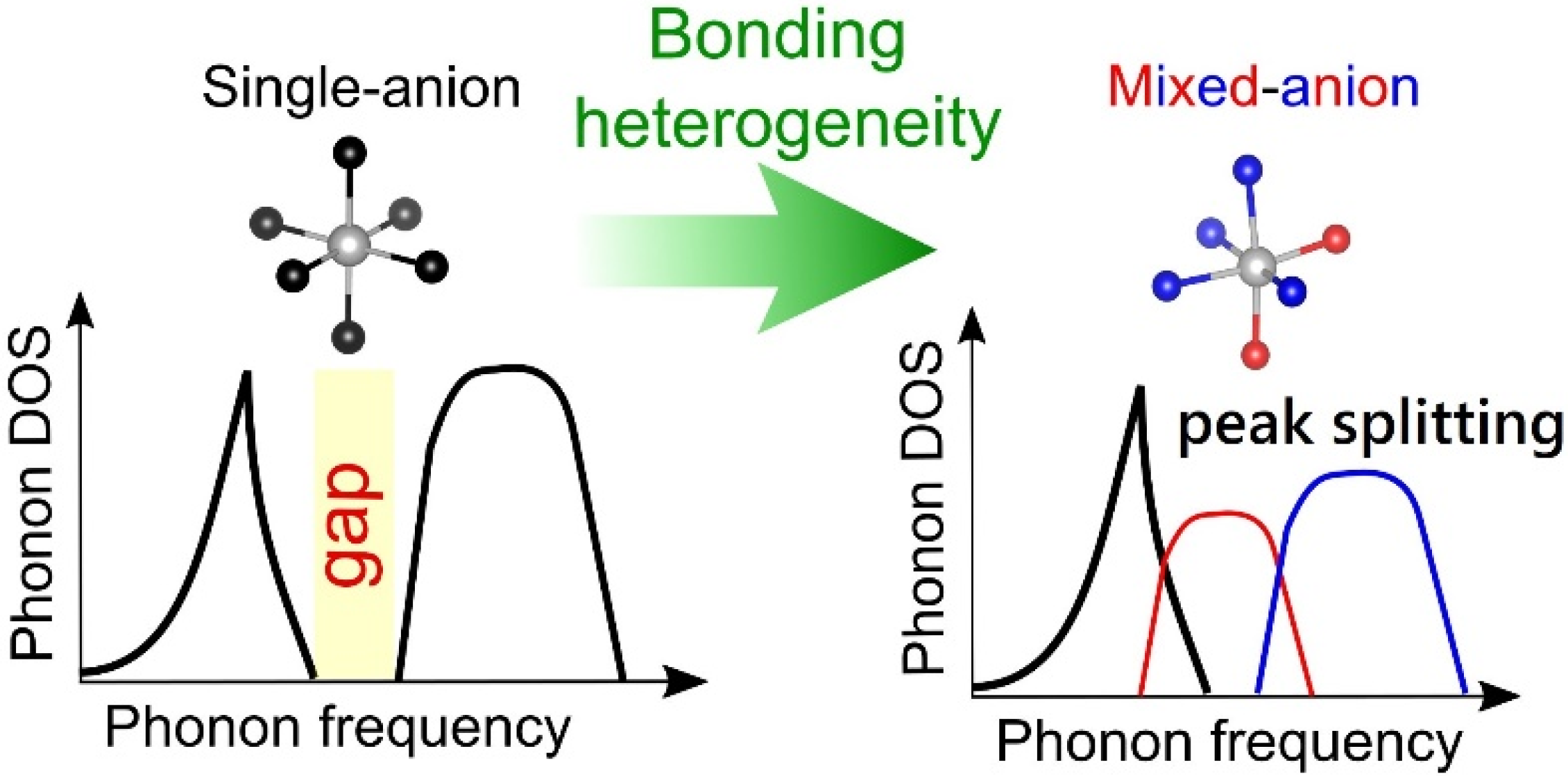
Example of thermal conductivity reduction effect due to mixed anions
The fact that bonding heterogeneity and anharmonicity can lead to very low thermal conductivity has been demonstrated by various groups for different compounds [63,64,65,66,67]. A recent work particularly focused on the mechanism of the mixed anion effect on thermal conductivity. It was revealed that the locally distorted crystal structure due to the mixed anion of chalcohalide MnPnS2Cl (Pn = Sb, Bi) causes the peak splitting of the density of states of phonons [67]. The peak splitting increases the phase space of phonon scattering, promotes 3-phonon scattering, and greatly reduces the thermal conductivity. In fact, the mixed anion MnPnS2Cl has a much lower lattice thermal conductivity value, 0.5 W/m/K, compared to 3.5 W/m/K of the single anion CuTaS3, which has similar proportions of heavy elements and similar crystal structure. Comparing the phonon densities of states of these two compounds (Figure 5), there is a phonon gap in the single anion CuTaS3, whereas in the mixed anion MnPnS2Cl, the gap disappears due to the aforementioned peak splitting. Although it is a compound mainly composed of relatively light element species, the heterogenous chemical bonding created by the mixed anion has a very strong thermal conductivity reduction effect and should be further exploited [67].
3.
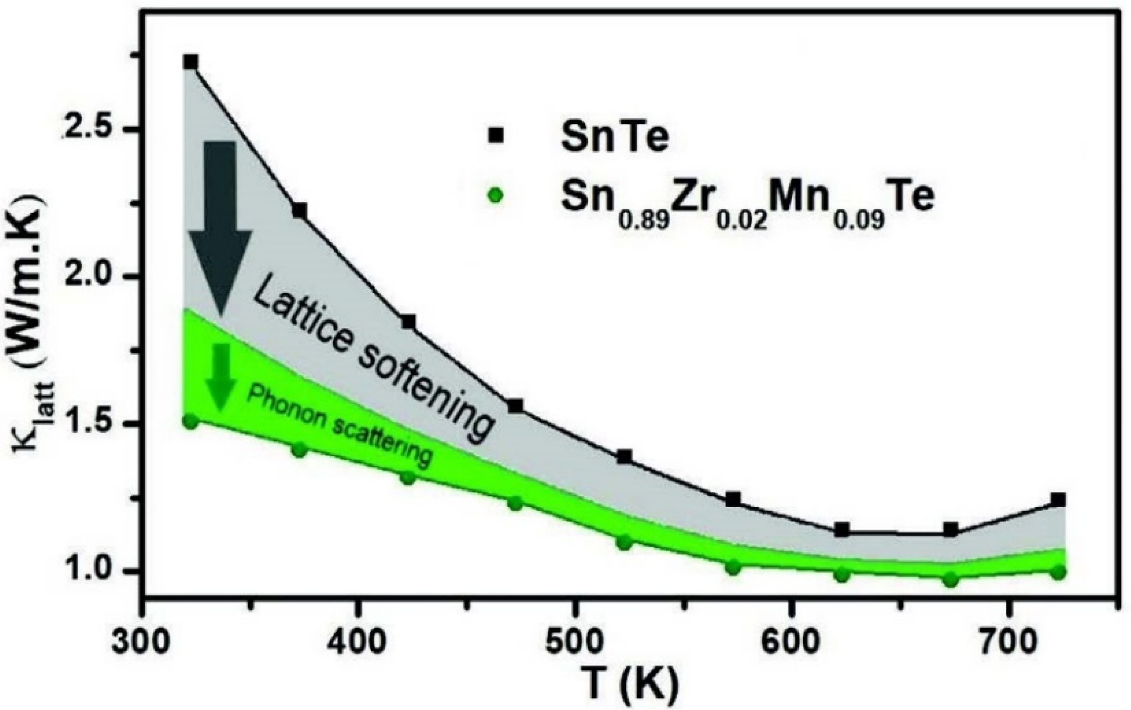
Lattice softening by doping
Some compounds, such as BiCuSeO, have weak lattice bonding to begin with [68,69], but specific atomic doping was shown to particularly soften the lattice and significantly reduce thermal conductivity. On single doping or co-doping Ti, Zr to SnTe, a red shift is observed in Raman spectroscopy, and despite this being light element atomic substitution and the lattice constant is also reduced, contrarily the bonding becomes weaker. The effect of phonon scattering due to atomic substitution was also estimated, and it was shown that the reduction in thermal conductivity due to the softening of the lattice is much more effective in this case (Figure 6) [70].
As a result of the lattice softening via doping, ZTav, which is an important parameter for the application of thermoelectric power generation, was able to achieve some of the highest reported performances in this Pb-free material system in the mid-range temperature region below 723 K [70].
Recently, the experimental control and theoretical understanding of defect formation has increased. In addition to enhancing traditional materials like Bi2Te3-type materials [71], defect engineering in “hot” new materials like GeTe and Mg3(Sb,Bi)2, has also enabled significant reduction in the lattice thermal conductivity and increases in power factor to achieve high ZT, and several detailed examples will be discussed below in Section 2.2.

2.2. Several Notable Thermoelectric Material Systems

2.2.1. High, Mid-High Temperatures

Since the renewed interest in the development of high-performance thermoelectric materials in the early 1990s, a relatively large number of inorganic materials have been investigated, leading to a large number of review articles and publications on the topic in the last ~30 years. The research has primarily focused on high-temperature materials for thermoelectric waste heat recovery. The materials investigated include advanced PbTe-based alloys, clathrates, half-Heuslers, oxides, and SKDs. The research has not only focused on the characterization and improvement of the materials’ thermoelectric performance but also on the device integration aspects, including mechanical properties and metallization of the thermoelectric materials. Although a quite impressive body of work has been performed and claims of peak thermoelectric figure of merit greater than 1 (sometimes largely greater than unity) have appeared in the literature, making the materials potentially attractive for commercial applications, no devices/systems integrating these materials are currently commercially available. There are several reasons for this, primarily technical but also economical and this review article covers some of these economic reasons.
SKD materials have often been the materials selected for device integration/development considering their relatively high thermoelectric performance and reasonable mechanical robustness for a thermoelectric material. SKD materials belong to a rather large family of compounds and solid solutions, whether filled or unfilled, offering many opportunities to tune their electronic and thermal properties. They are optimal for thermoelectric applications in the 573–973 K temperature range with thermoelectric figure-of-merit peaks greater than unity. Uher recently published a comprehensive review of SKD materials, which provides a wealth of fascinating information and properties for these materials [72]. Two notable projects funded by the US Department of Energy, one led by General Motors and the other by Gentherm, were initiated in about 2010 and aimed at developing a cost-effective thermoelectric generator (TEG) to reduce automotive energy consumption and CO2 emissions by generating usable electricity from exhaust gas waste heat. Both teams selected the SKD materials for the TEG development. Significant technical progress was achieved by both teams and the results were documented in two final reports [73,74]. The technology was eventually not commercially implemented but the technical barriers were not as significant as the economic barriers, some of which, again, will be analyzed in this article.
PbTe is a well-known high performance mid-high temperature thermoelectric material [75,76], previously utilized in RTGs at an early time. Because Pb is a restricted toxic element, for terrestrial applications, there has been effort carried out to develop related Pb-free materials.
SnTe is such a Pb-free related material and various efforts have been carried out to enhance the ZT, utilizing principles such as were described in the previous Section 2.1. For example, In doping has been found to function as a resonance level and various other doping also carried out for band engineering approaches [77].
Magnetic ion Mn doping in SnTe was indicated to successfully realise interaction between the magnetism and charge carriers, and also resulted in enhancement of power factor [43]. Various nanostructuring such as listed in Section 2.1 has also been extensively applied to SnTe and coupled with the other tuning, high values of ZTmax exceeding 1 have been obtained [78]. However, these high values are limited to a narrow range above 823 K, and ZTav is not particularly high. Lattice softening via certain doping resulted in a high ZTav in the range 323 K to 723 K as described above in Section 2.1 [70].
GeTe is also a recently very extensively studied system with a base higher ZT than SnTe. As noted in Section 2.1, the defects in GeTe have been particularly utilized to obtain high performance and coupled with band engineering, ZT ≈ 2 or higher has been reported by various groups [79,80,81,82].
A few examples of the utilization of defect engineering in GeTe will be given. It was discovered that Cr doping in GeTe had the serendipitous effect to lower the formation energy of Ge defects. This led to creation of homogenously distributed Ge precipitations and Ge vacancies, which effectively selectively scattered phonons, and coupled with typical band convergence doping to enhance the power factor, resulted in high ZT~2 (Figure 7a) [81]. Focusing on the correlation of crystal structure and defects, and their effects on charge transport, led to high power factors and high ZTav~1.2 from 300 K to 723 K for Pb-free GeTe [82]. Compositing approaches leading to strong phonon coupling increases ZT, and very high ZT > 2 has been reported for some GeTe composites [79,80].
One applicative issue of GeTe is that it is predominantly p-type and for typical module applications, an n-type counterpart is necessary. A high entropy doping approach of AgInTe2 alloying into GeTe was carried out. High entropy tends to stabilize the phase with higher symmetry and as a result, this doping stabilized the cubic phase. The cubic phase of GeTe forms defects more readily, and thereby it became possible to dope the electron donor Bi in larger amounts, leading to the first stable n-type conduction in GeTe as illustrated in Figure 7b [83].
The performance of GeTe is geared toward mid-high temperatures, however, one interesting approach reported that quenching of GeTe in the synthesis process, shifted the ZT peak of GeTe to lower temperature to approach the performance of Bi2Te3-type materials [84]. From a cost standpoint, GeTe is significantly more expensive than Bi2Te3-type materials, so the impetus to use it as a replacement material is not strong, however, this appears to be another good example of physical properties control.
A striking high performance of ZT = 2.6 was reported for doped AgSbTe2 at the relatively low temperature of 573 K by some tuning of the properties via atomic disorder [85].

2.2.2. Low Temperature Region

Bi2Te3-type materials have been the long-time champion thermoelectric materials in the low temperature region from RT to 563 K. There have been many reviews written on Bi2Te3-type materials [86,87,88], so we will not cover them here, rather focusing on new developments.
The thermoelectric properties of Mg3Sb2-type compounds were studied at an early time [89], and these materials gained renewed attention when Kanno and coworkers and Iverson and coworkers, respectively, focused on the band degeneracy aspect (Section 2.1) and doping tuned the materials to obtain high performance [90,91]. Recent further advancements have been made, for example, via alloying with Mg3Bi2 [92] and various dopings [93] to control the band structure and scattering of thermal conductivity to achieve significant enhancement of ZT. These and other developments have been reviewed well [94].
As a very recent result, a striking dual effect of Cu minor doping in Mg3Sb2 was revealed (See Figure 8). These can in a wide view considered to be a type of defect engineering. The doped Cu atom is thought to enter two different places in the material. First, interstitial Cu doping was indicated to lower the phonon group velocity of high-frequency optical phonons which generally make a large contribution to the thermal conductivity in Mg3Sb2. Secondly, Cu doping into the grain boundaries promoted grain growth and importantly, suppressed the scattering of charge carriers by modifying the structure and composition near the grain boundaries. As a result, very high mobilities similar to single crystals were achieved, while being a polycrystalline material with low thermal conductivity [95].
By adjusting the processing conditions, namely the spark plasma sintering (SPS) temperature, and shifting the composition to Bi-rich, there was success in improving the performance of the Mg3(Sb,Bi)2-type material in the low temperature range near room temperature [96].
As summarized above, the Mg3Sb2-type compounds show n-type high performance at relatively low temperatures, and as another non-tellerium system, for the p-type, MgAgSb compound has emerged. As a pioneering work on MgAgSb, processing and doping were optimized to achieve a high low temperature ZT of ~1.4 at 450 K [97].
Relatively high performing modules of these new materials have been constructed and tested and will be detailed below in Section 3.3.

3. Advances in Thermoelectric Device Design and Fabrication

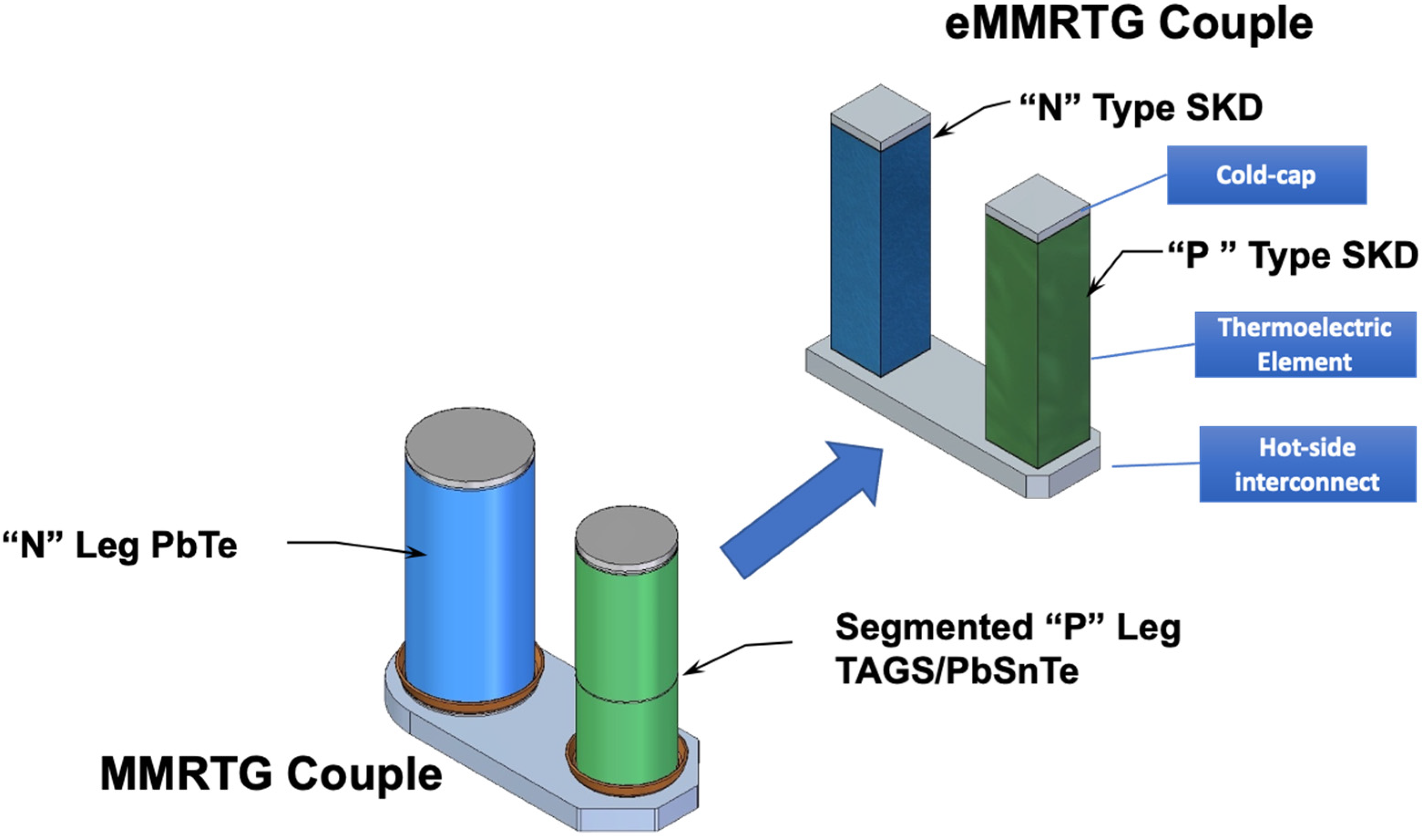
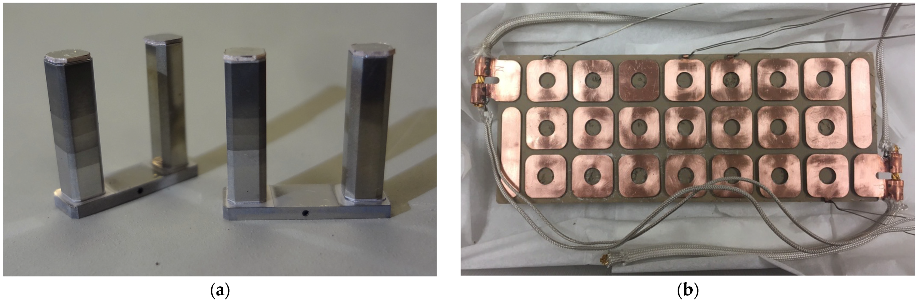
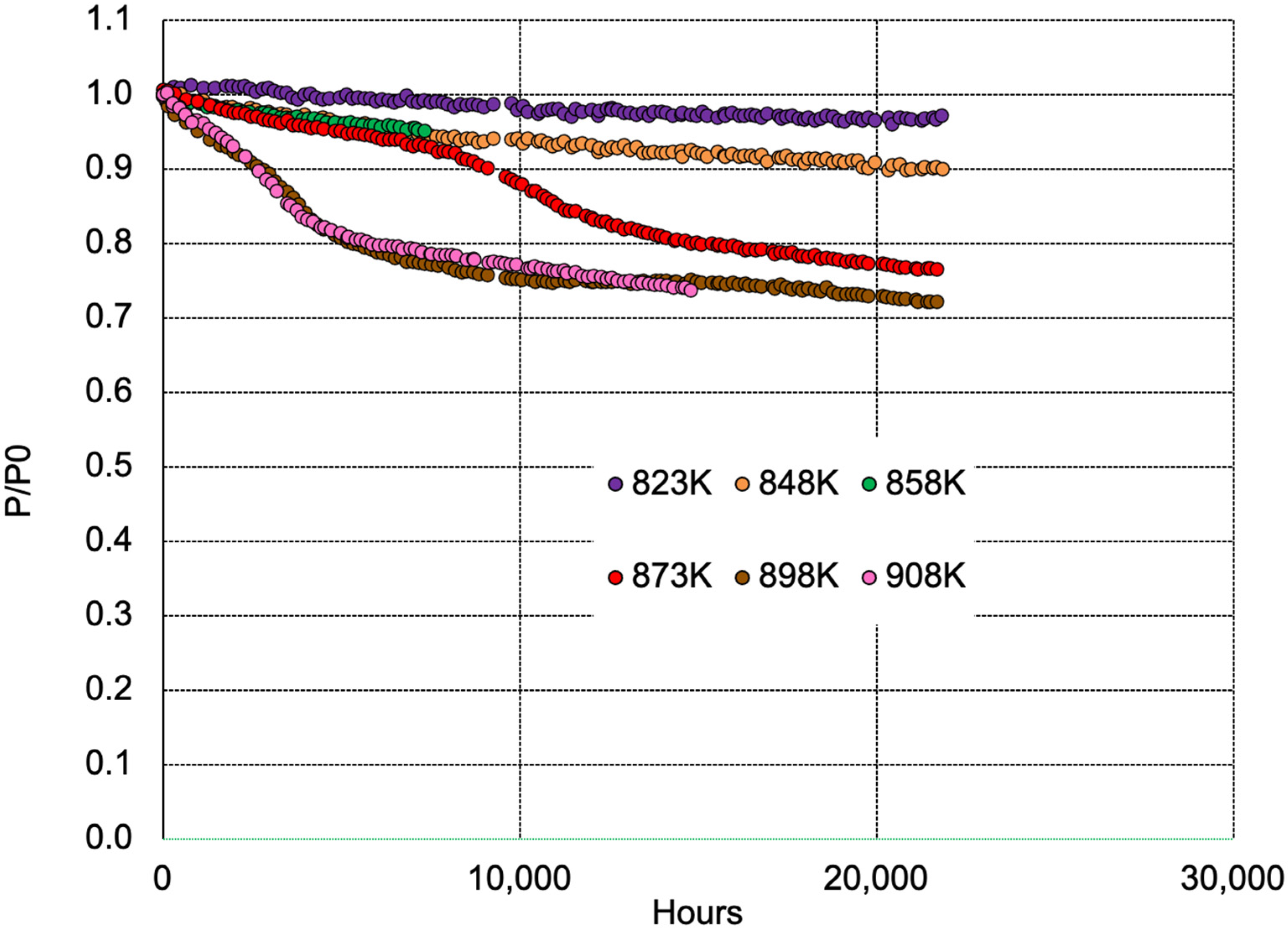
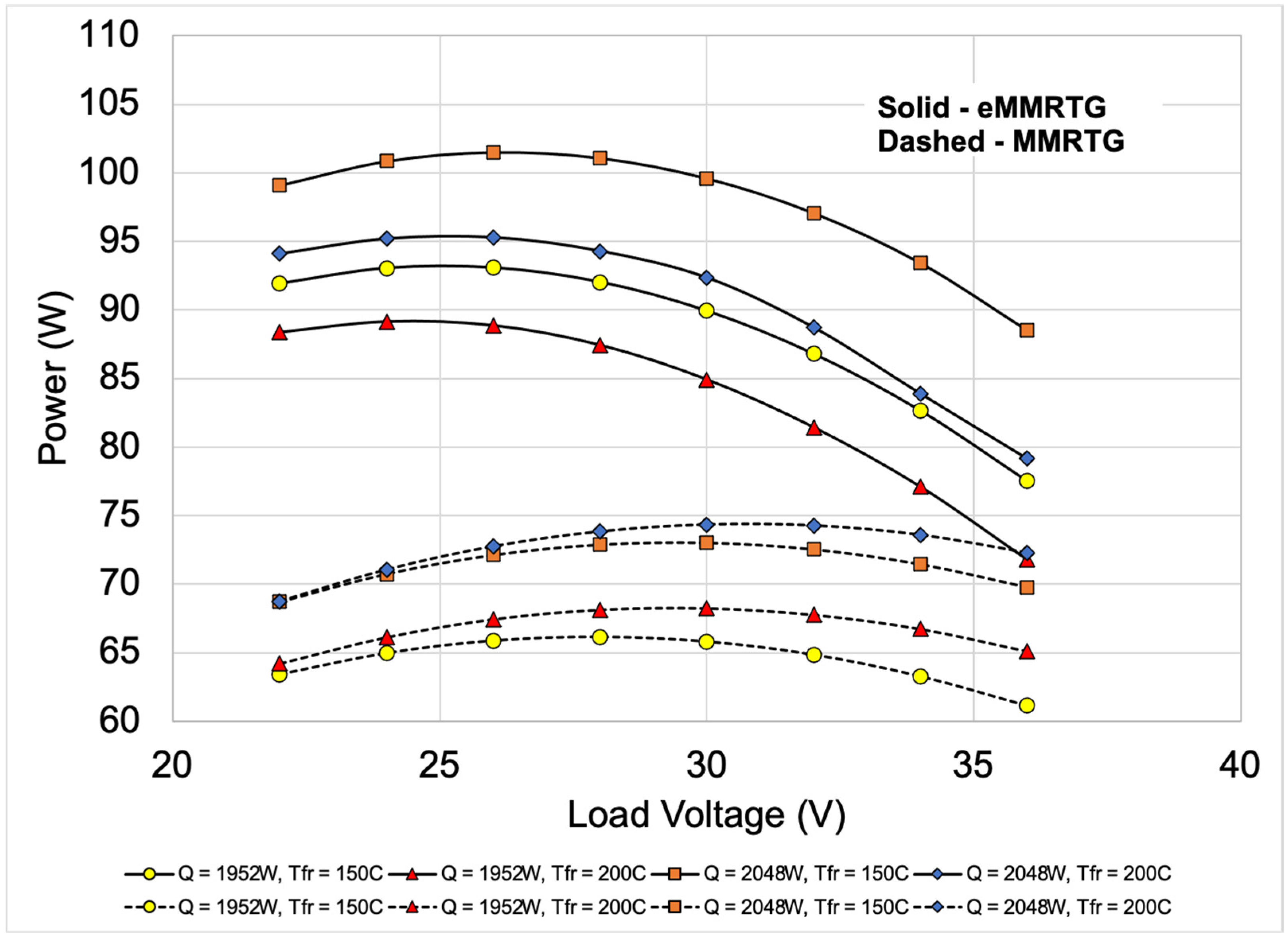
3.1. SKD-Based Thermoelectric Converters Development at NASA Jet Propulsion Laboratory

As previously mentioned, the intense search for higher performance thermoelectric materials over the last ~30 years have unfortunately not led to any new, commercially available devices/systems. However, in several areas, where, for example, cost is not necessarily the primary driver for implementation such as defense or space applications, some device/system development has occurred. An example of this is the potential use of SKD materials to retrofit the flight-proven Multi-Mission Radioisotope Thermoelectric Generator (MMRTG) that is currently used on Mars to power the Curiosity and Perseverance rovers.
The NASA Jet Propulsion Laboratory (JPL) proposed the enhanced Multi-Mission Radioisotope Thermoelectric Generator (eMMRTG) concept in late 2013. It is based on retrofitting the flight-proven MMRTG that uses PbTe/TAGS thermoelectric couples with higher-efficiency thermoelectric (TE) couples based on SKD TE materials developed at the Jet Propulsion Laboratory (JPL) while keeping the balance of the system virtually unchanged. A multi-organization team composed of Teledyne Energy Systems, Inc. (TESI), Aerojet Rocketdyne (AR), and the Jet Propulsion Laboratory (JPL) have collaborated to develop and mature the SKD-based thermoelectric converter technology and to establish the potential for the SKD-MMRTG to deliver a minimum of 77 We after 17 years.
The flight-proven MMRTG is composed of sixteen, 48-couple modules composed of PbTe/TAGS thermoelectric couples packaged in fibrous insulation and is operated under inert gas in a hermetically sealed environment that contains O2 and H2 getters. The MMRTG uses the decay of PuO2 fuel as thermal input for the 48-couple modules and produces about 110 We at the beginning-of-life (BOL). The potential eMMRTG is nearly identical to the MMRTG except for substituting the upgraded 48-couple SKD modules for the PbTe/TAGS 48-couple modules.
The SKD materials under consideration for the SKD-MMRTG are based on CoSb3 for the n-type materials and Ce0.9Fe3.5Co0.5Sb12 for the p-type materials. Figure 9 illustrates the differences between the heritage MMRTG and eMMRTG couples. The length of the couple is identical to preserve the same spring-loading of the modules in the generator. However, due to manufacturing constraints, the cross-section of the SKD couples is square instead of circular like the MMRTG couples. The p-leg of the SKD couple is segmented to optimize the mechanical robustness and TE performance. The cross-sections are optimized to achieve an optimal hot-junction temperature for the thermoelectric that balances degradation over time and power output. Several iterations of SKD couple development have been completed with evolving configurations to achieve a robust design with the potential to achieve the eMMRTG life performance goals.
Figure 10 shows pictures of the current eMMRTG couple design and the 1st 48-couple module that was fabricated. Beginning-of-life performance testing of these couples demonstrates that their power output is within a few percent of the predicted values. In the 48 couple-module, the couples are connected in series-parallel to augment redundancy. A combination of critically dried SiO2-based aerogel and bulk fibrous insulation (Promalight®) encapsulates the individual couples in the module. The critically dried aerogel, adjacent to the legs, is cast around the legs establishing intimate contact with the couple legs. This level of encapsulation provides a sublimation barrier to keep the antimony sublimation to an acceptable level for long-term operation. In combination with the SiO2-based aerogel, the bulk fibrous insulation provides a low thermal conductance path around the couples to maximize the heat input into the TE legs. As a result, the generator has a thermal efficiency of about 90%. Since the development of PbTe/TAGS and SiGe-based RTGs in the 1950s and 1970s, respectively, the SKD 48-couple module represents the first development of an RTG thermoelectric converter in over 50 years!
At the generator-level following conditions: Tfin root = 430 K, QBOL (PuO2) initial thermal inventory) = 1952 W, and Vload (bus voltage) = 34 V, the hot-junction of the couple legs is nominally at 848 K. With the radioisotope fuel decaying over time, the hot-junction temperature will decrease by approximately 30 K over 17 years. However, potential mission environments may result in higher hot-junction temperatures. Therefore, it is necessary to test above and below 848 K to characterize the couple’s degradation rate as a function of time and temperature. When higher temperatures do not introduce new degradation mechanisms, testing can be considered accelerated testing. Accelerated testing can contribute to establishing a 17-year performance prediction for the generator with more confidence. JPL and TESI have been conducting testing SKD couples at 823, 848, 858, 873, 898, and 908 K. These test articles were started at different times and therefore have different cumulative test durations with a longest of over 20,000 h. Figure 11 shows the normalized power for couples as a function of time and temperature. The generator-level life-performance prediction model used couple-level data to establish degradation parameters. Figure 12 shows the normalized measured and predicted power output for the 48-couple module. The measured data is in excellent agreement with the prediction with up to approximately 9000 h of data.
The end-of-design-life (EODL) power requirement is verified using a combination of couple life test data acquired from thermoelectric couples/devices and a physics-based life performance prediction model. Figure 13 shows the current best eMMRTG and MMRTG 17-year power output prediction estimate. The predictions are a function of beginning-of-life fuel inventory (Q), generator fin root temperature (Tfr), and load voltage (V). The typical load voltage for the Mars Science Laboratory (MSL) and M2020 MMRTGs is about 30 V. At equivalent conditions, the eMMRTG could deliver at least 38% more power than the MMRTG. This significant improvement could enable more science for a spacecraft or rover using an eMMRTG compared to an MMRTG.
Figure 11. SKD couples normalized peak power as a function of time and temperature.
Energies 15 07307 g011
Figure 12. Measured and predicted power values for the SKD 48-couple module are in excellent agreement.
Energies 15 07307 g012
There have also been significant advances in high-temperature TE module design and fabrication for aircraft and commercial industrial energy recovery applications at mid-range temperatures near 773 K. Jet Propulsion Laboratory focused their research and development in 2015–2019 on designing and implementing SKD materials technology into these applications. Jet Propulsion Laboratory (JPL) in 2018 developed and tested the first high-performance, SKD-material-based module that demonstrated the highest TE module conversions efficiency (i.e., 10%) at that time (2018), operating at hot-side temperatures of about 703 K and cold side temperatures of about 293 K. This module design could easily operate up to hot-side temperatures of 798 K. Figure 14 shows this high-performance TE module and its overall footprint dimensions and layout. In addition to JPL testing, this performance was ultimately verified at the Army Research Laboratory, Adelphi, MD. This advanced TE module also demonstrated the highest power output in a SKD-based module, measured at approximately 20 We at the temperature conditions stated above, and the highest reported power density, approximately 3.8 W/cm2 at the module level, of any TE module worldwide at that time [98]. This TE module also had the highest TE element fill factor (~41%) reported at that time. This represented a major advance in SKD TE module technology and still serves as a major stepping stone and critical reference design in SKD-based TE module technology.
Figure 13. Comparison of current-best-estimate eMMRTG and MMRTG 17-year power output prediction as a function of beginning-of-life fuel inventory (Q), generator fin root temperature (Tfr), and load voltage (V). The prediction assumes 3 years of storage followed by 14 years of operation.
Energies 15 07307 g013

3.2. Low Temperature Module Directions

Another aspect of thermoelectric power generation modules is their potential to act as a power source for IoT sensors and devices, at lower temperatures near room temperature. It has been said a trillion sensors are necessary to support future society, and the periodical replacement of batteries of such are not feasible. Therefore, some dynamical technology to continuously harvest energy from surroundings is necessary, and thermoelectrics is one of the candidates [2,10,11,12,13,14].
Regarding the form of module, various formats have been proposed. Foremost, are flexible material-based modules which have the potential to be wearable. Various modules of polymer materials, organic-inorganic hybrid materials have been proposed and reviewed extensively [10,13,99,100,101,102,103].
The ductile inorganic Ag2S material has also been raised as a candidate for flexible applications [104]. The unusual ductile nature for an inorganic material is attractive. In the case of thermoelectrics, several applicative issues need to be solved. Namely, one perceived advantage of the polymer-based module is the relatively inexpensive synthesis and/or module fabrication, and potential for fabricating relatively large area devices. However, the performance of polymer-based materials and modules is generally significantly lower than the best inorganic materials and modules. Additionally, the temperature difference which can be obtained from wearable application is relatively small, so the output power is small, and highest performance from the materials themselves is desirable. Another issue is that it has been pointed out that many of the polymer-based modules ultimately use expensive metal (e.g., silver, gold) pastes as contacts, so are actually not inexpensive and different approaches may also be necessary to consider [105,106]. In the case of Ag2S or Ag2Se- based materials, they have relatively high performance, however, the materials with silver as the major component are quite costly, and inexpensive module fabrication methods also need to be developed. However, it has been pointed out that in general, glassy chalcogenides have advantages in rapid synthesis and shaping [104,107,108,109]. Utilizing Bi2Te3-type materials on flexible substrates has also been considered and developed [110,111], with higher performance than polymer-based counterparts, but not all the fabrication methods are industrial, and sustainability of using Bi2Te3 for ubiquitous applications also needs to be considered.
The overall economical strategies of thermoelectric will be discussed below in Section 4. In terms of materials costs, it is not just the cost of the raw materials, but inexpensive and up-scalable synthesis methods are also critical [112]. It should also be mentioned that the IoT applicative direction is not as cost sensitive as higher temperature energy saving applications.
For IoT powering modules, recent efforts have also picked up regarding constructing thermoelectric power generation modules utilizing semiconductor fabrication technologies. The obvious benefits of this, is the compatibility with industrial processes, and also possible miniaturization, and/or integration with semiconductor devices. Earlier efforts have been reviewed in [10]. For example, micro electro mechanical systems (MEMS) standard processes were utilized to construct several different modules, e.g., based on Ni-Cu-based thermocouples [113], n-type and p-type poly Si [114].
More recently, Nomura and coworkers fabricated a poly Si-based CMOS TEG, with an important improvement that they addressed the issue of the problem of such devices having difficulty applying temperature difference on the thermoelectric material elements. Namely, the Si membrane was nanopatterned based on the thermal phonon mean free path spectrum to significantly lower the thermal conductivity and enhance output voltage and power density [115]. p- and n- Si nanowire based planar thermoelectric generator has also been constructed by CMOS technology [116]. The power output of these new modules are still relatively small, with a maximum of 12 nW/cm2 with DT = 40 K and 1.4 nW/cm2 with DT = 20 K, for the CMOS poly Si and Si nanowire modules, respectively.
An organic thermoelectric power generation module was constructed using industrial technologies of photolithography, fulfilling, and electrode deposition [117]. In total, 250 mV of output voltage was generated, however, the extremely high contact resistance resulted in a total resistance of 13 MW for the module, highlighting the issue of the electrode contact in organic/polymer-based modules.
As a different approach from the Si-based CMOS devices mentioned above, an in-plane miniaturized inorganic thermoelectric device using a Mg2Sn-type thin film [118] was constructed utilizing microfabrication techniques of photolithography and dry etching (Figure 15) [119]. The microfabricated devise displayed a relatively high output voltage of 0.58 V and an output power of 0.6 mW, corresponding to a comparatively high output power density of 21 mW·cm−2, only considering the active material. However, the sapphire substrate had a thickness close to 2000 times the thickness of the Mg2Sn-type thin film, and therefore, temperature difference on the thermoelectric material was difficult to be applied. Namely 110 K was applied to the whole construct including the thick substrate, to obtain the modest output described above. Reducing the substrate contribution is an immediate improvement in design which should be undertaken.
To summarize, much effort is recently being made to fabricate a wide variety of modules for possible IoT application. While material development trying to find higher performance polymer-based thermoelectric materials including hybrids, and Bi2Te3-type replacement materials should continue, the module design and fabrication is a critical issue. The challenges for the different types of module have been simply raised. It is hoped these activities can lead to viable usages of thermoelectric power generation for the myriad IoT sensors and devices.

3.3. Module Fabrication of New Materials

There have been several test modules fabricated for the most recent new generation of thermoelectric materials described above, such as for GeTe and Mg3(Sb,Bi)2-type.
First of all, for the mid-high temperature GeTe, very high performance for a single leg has been reported, indicating the high potential of the material system [120]. A realistic for application 8-pair module was constructed using p-type GeTe and a SKD for n-type. As mentioned in Section 2.2.1, GeTe is predominantly p-type. A maximum conversion efficiency of 7.8% was measured with a hot temperature side of Th = 800 K and DT = 500 K [121].
Regarding Mg3(Sb,Bi)2-type materials, which are predominantly n-type for the high performance materials, relatively early demonstrations were made for Peltier modules with (Bi,Sb)2Te3-type materials used for p-type. Comparative cooling performance to Bi2Te3-type was demonstrated by Mao et al. for a single pair [122]. Recently, for a 7 pair Mg3(Sb,Bi)2-type/(Bi,Sb)2Te3-type module, a maximum cooling DT of 76 K with Th of 350 K, which is comparable to Bi2(Te,Se)3-type/(Bi,Sb)2Te3-type modules [123].
For power generation with Mg3(Sb,Bi)2-based modules, the Cu minor doped material described in the materials development, enhancement principles in Section 2.2.2 yielded high performance (See Figure 16). Differing from above, for the p-type material also, a new non-(Bi,Sb)2Te3-type material was used, i.e., similarly Cu minor doped and enhanced AgMgSb [95]. The 8-pair realistic module composed of new n- and p-type materials exhibited an efficiency of 7.3% (Th = 593 K). This performance rivals the best Bi2Te3-type modules which have been champion for more than half a century [95]. The conversion efficiency estimated from the material performance is close to 11%, and further improvement in performance can be expected in the future. The electrode contact resistance and moreso the process by which the electrodes are fused on to the thermoelectric material are points for improvement. This is a good example where the materials development, i.e., application of enhancement principles, lead to a high performance thermoelectric material and module composed of new materials.
Furthermore, attempt to shift the high performance of these materials and module to near room temperature was also carried out. As described in the previous Section, by adjusting the processing conditions and composition, the performance in the low temperature range near room temperature was enhanced [96]. The power generation performance of an 8 pair module was evaluated to yield a conversion efficiency of 2.8% with low temperature side of 278 K and high temperature side of 373 K (See Figure 17). This performance is comparable to the Bi2Te3-type modules. Moreover, in the evaluation of the cooling performance in which the high temperature side was fixed at 323 K, the maximum temperature difference reached 56.5 K, and it was shown that the cooling performance was also high (See Figure 17). These results show that even an initial module using the almost Te-free and significantly more abundant-element-composed newly developed thermoelectric materials, has shown performance comparable to the Bi2Te3-type modules even near room temperature.
Other modules or single pair using the Mg3(Sb,Bi)2-type material have been constructed and tested [124,125].
There is also a renewed focus also on developing better electrode materials than Fe for Mg3(Sb,Bi)2-type, such as Mg2Cu alloy [123] and Fe7Mg2Cr/Ti alloys [126]. Several application issues have recently been discussed in the following review [127]. These activities show the high expectation for Mg3(Sb,Bi)2-type to become the long-awaited Bi2Te3-type replacement material.

4. Thermoelectric System Economics

This article and Special Issue discusses several applications ranging from low-power IoT power generation, requiring mW’s up to 1 We powering monitoring sensors and various network electronics, up to high-power waste energy recovery (WHR) power generation, producing 100’s We up to 1–3 kWe. In the low-power IoT applications the cost per power [i.e., $/We] are not as important as it does not matter too much whether the TE system cost per power is $1/We or $10/We. This is a growing field with much promise for small, compact, highly reliable TEG systems for IoT monitoring and response networks. In contrast, high-power thermoelectric power systems, particularly those targeting waste heat recovery applications, require cost-performance optimized designs with high thermal and thermoelectric (TE) performance and low costs to surmount common commercialization barriers controlling the acceptance of TEG systems. Past TEG system designs and applications have struggled with and been ladened with the perception and reality that TEG systems are high-cost for the relatively low power produced compared to other power systems. Recent TEG systems in waste energy recovery applications have been investigated, designed and prototypically demonstrated in a few applications worldwide [8,128,129,130,131,132]. These investigations and prototype demonstrations generally emphasized characterizing one or more key design factors: (a) TE power output, (b) TE system voltage and current performance, (c) TE system electrical resistance, (d) resistance matching, and (e) TE power outputs from a few tens of watts to 700 We. However, they generally did not consider and were not driven by TEG system cost considerations. TEG system cost optimization is a crucial to governing final decisions on commercialization of high-power TE energy recovery systems in all terrestrial applications; cost often more critical than power density or efficiency in the adoption of waste energy recovery (WHR) TEG systems. In general, integrated TEG system cost-performance analysis has only recently been rigorously investigated by Hendricks et al. [6,7,133,134,135], LeBlanc et al. [135] and Yee et al. [136]. Critical foundations and critical mathematics and relationships have been developed through these works, allowing one to understand crucial complex interrelationships and dependencies governing TEG system integrated cost-performance optimization. Integrated cost-performance analyses have focused on a generalized system-level thermal/electrical circuit shown in Figure 18.
Most recently Geffroy et al. [137] have investigated the temperature and power criteria required to make waste heat recovery (WHR) engines of any type economical using techno-economic analysis and thermodynamic and heat transfer arguments. Their work indicates that WHR (i.e., waste energy recovery) applications must have available temperatures above 150 °C and power generation above 100 kW. This offers added emphasis and motivation for investigating the thermoelectric systems economics (TSE) of only high-power thermoelectric systems, those that could be employed in industrial processing, aircraft engine energy recovery, or perhaps marine and ocean vessel systems. Much discussion in waste energy recovery circles has centered on the topic of what cost per energy levels are acceptable and must be achieved by thermoelectrics systems. Geoffroy et al. [137] point out that organic Rankine power systems that could be used in waste energy recovery generally have cost per power values of $0.375/We and modern geothermal energy recovery plants operate at about $1.2/We. Hendricks [134] further pointed out that modern solar photovoltaic systems cost out at ≤$1/We. This all points toward the need for WHR thermoelectric systems to cost out as close to $1/We as possible and this will serve as a reference comparative criteria used in following cost-performance discussions.
Recent TSE research by Hendricks [6,7,134,138] has established new integrated cost-performance relationships elucidating new design paradigms in cost optimization (i.e., minimizing [$/We]) of TEG systems. New integrated cost-performance relationships show critical tradeoffs between the key TEG component costs (heat exchangers, TE materials, and TE manufacturing costs) and performance, allowing one to differentiate magnitudes of competing cost and performance effects. New design paradigms and relationships demonstrate a holistic approach providing enhanced understanding and crucial interrelationships between heat exchanger design parameters, TEG component costs, TE design parameters and material properties, and interfacial heat flux in minimizing TEG system costs. This work herein now extends that integrated holistic cost-performance analysis to include critical thermal and electrical interface contact resistance effects into the cost-performance relationships, and incorporates and extends insight into the effects of manufacturing cost-sensitivities to TE element design, thereby providing even broader in-depth insight into cost-optimized TE design to further complete and expand the new TSE paradigms. Hendricks [134] has most recently expanded this integrated cost-performance relationships, showing the relationship between optimum fill factor and optimum cost per watt, to include the effects of thermal and electrical contact resistances and their inherent impacts on cost effectiveness of TEG systems. Equation (2) through (4) highlight and summarize these latest relationships, with Equations (5) and (6) providing crucial peripheral relationships involved in the integrated cost-performance optimization and key parameter interdependencies.
F = A T E A H E X
F o p t = 1 4 ( ( C H E X , h + C H E X , c ) U A u C L T E 3 + C L T E 2 ) ( L T E 2 A H E X ) + 1 4 ( ( C H E X , h + C H E X , c ) U A u C L T E 3 + C L T E 2 ) 2 ( L T E 2 A H E X ) 2 + 8 1.1 ( ( C H E X , h + C H E X , c ) U A u C L T E 3 + C L T E 2 ) ( L T E 2 A H E X ) ( K H L T E κ T E A H E X )
G o p t ( S p n Δ T ) 2 σ L T E · m 4 ( C L T E C + 1 ) C L T E 2 ( 2 ρ c o n L T E ρ a v e + 1 ) ( 1 + 2 r l c L T E ) ( m + 1 ) 2 = [ 1 + 1.1 κ T E A H E X F o p t K H L T E ] 2 [ 1 + ( ( C H E X , h + C H E X , c ) U A U ( C L T E C + 1 ) C A H E X F o p t ) ]
Additionally,
ΔT = (TexhTamb) = ΔTH + ΔTTE + ΔTC
where:
ΔTH = Hot-Side Heat Exchanger Temperature Differential [K}
ΔTTE = Thermoelectric Device Temperature Differential [K}
ΔTC = Cold-Side Heat Exchanger Temperature Differeial [K}
q H = K H · T H A H E X
Equations (3) and (4) demonstrate that optimum thermoelectric system cost, Gopt, depends on complex interactions and interdependencies of six 6 thermal and thermoelectric design parameter groups:
  • [κTE LTE/KH]—Non-dimensional parameter tied to TE Device/Heat Exchanger interfacial design parameters
  • [Fopt AHEX/LTE2]—Non-dimensional parameter tied to TE device design
  • where: [κTE LTE/KH]⋅[Fopt AHEX/LTE2 ] = [κTE Fopt AHEX/KH LTE] in first term on right-hand side of Equation (4)
  • [CHEX UAU]/[(C‴ LTE/C″ + 1) C″ AHEX Fopt]—Non-dimensional parameter tied to the ratio of heat exchanger costs to TE device costs
  • [κTE AHEX/(KH LTE)]—Non-dimensional parameter tied directly to interfacial heat flux
  • [ 2 ρ c o n L T E · ρ a v e + 1 ] · [ 1 + 2 · r · l c o n L T E ] 2 —Non-dimensional parameter tied directly to thermal and electric interface contact resistance effects as discussed in Hendricks [133] and Min and Rowe [137,139]
  • 1/[(SpnΔT)2⋅σ⋅LTE]—Thermoelectric power factor tied directly to TE properties
These two relationships demonstrated the complex dependences governing thermoelectric system cost-performance in high-power thermoelectric energy recovery discussed herein.
Equations (4)–(6) elucidate a critically important tradeoff in thermoelectric system energy recovery design, that being the key tradeoff between the overall ΔT that the TE system operates across, that portion that is across only the TE device, ΔTTE, and that portion across only the hot-side heat exchanger, ΔTH. This point is highlighted here to clearly reveal that, although one generally wants as high a ΔT as possible in any given WHR application (i.e., high ΔT applications favor low-cost systems through Equation (4)), there is an important tradeoff in thermoelectric design between the ΔTTE and ΔTH. High ΔTTE is generally desirable to achieve high TE device power conversion efficiencies, while high ΔTH is often desirable to increase the hot-side heat flux through Equation (6). Therefore, there is this critically important interplay between the ΔTTE portion and ΔTH portion of the overall ΔT given in Equation (5) when seeking and achieving optimized cost-performance TE system designs.

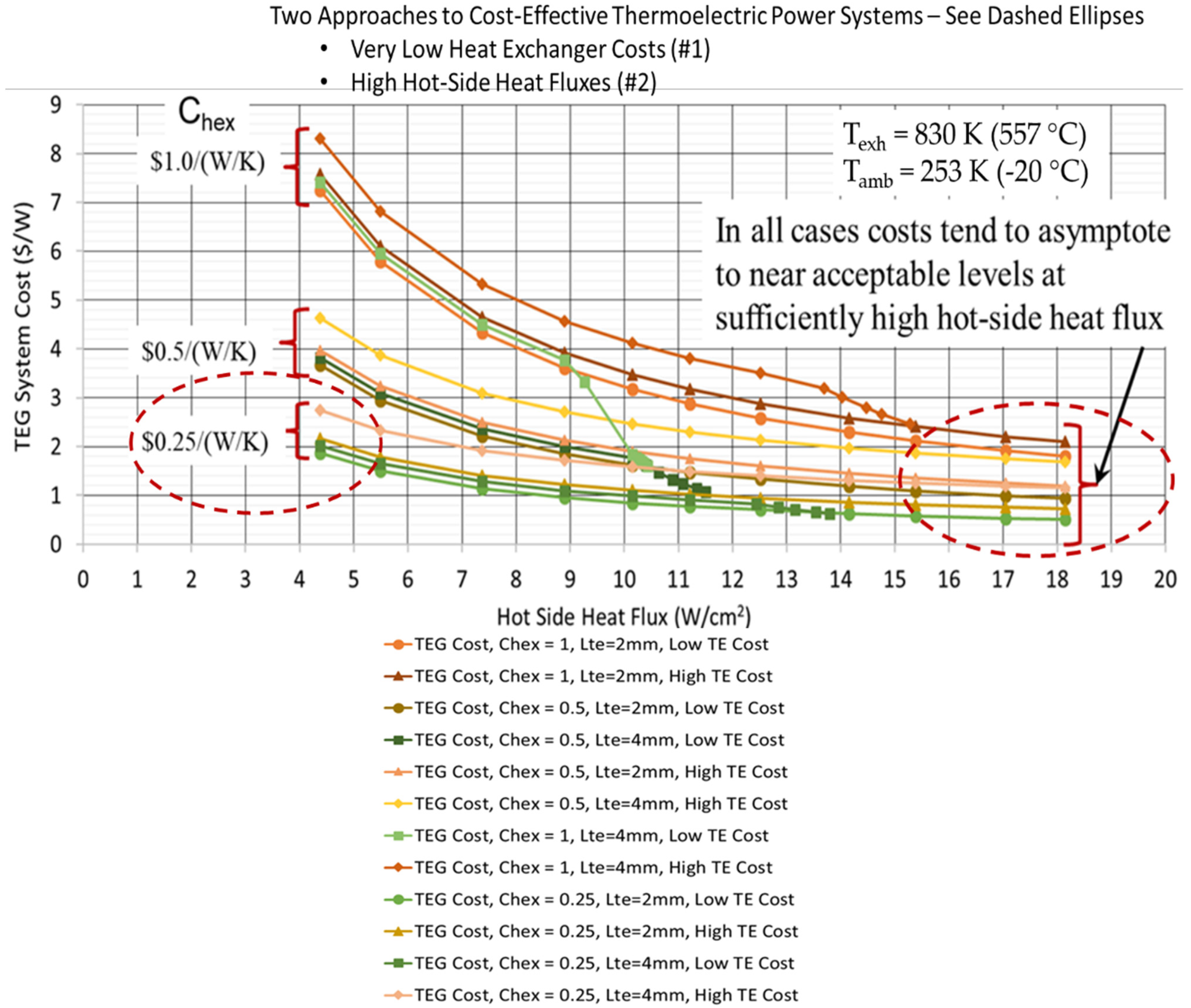
4.1. Hot-Side Heat Flux Effects in TEG Cost-Performance Optimization

A critically important effect and interdependency discovered from Equation (4) is the significant impact of TE hot-side heat flux on TE system-level costs. Sensitivity studies of this relationship was performed as follow-on work to Hendricks [6] by first assuming thermal and electrical contact interfaces were near ideal, or r = 0 and ρcon = 0, in Equation (4). This allows one to focus on the impact of hot side heat flux represented by Equation (6) on the optimized TEG system cost, Gopt, in Equation (4).
Figure 19 demonstrates the resulting relationship between system hot-side heat flux, heat exchanger costs, and TE material costs and overall TEG system cost derived from Equations (3), (4) and (6) for an illustrative exemplary TE system cost-performance analysis case (waste heat recovery application) where Texh = 830 K, Th = 700 K, Tamb = 253 K, and ΔT = (Texh—Tamb) = 577 K. Thermoelectric properties and thermoelectric materials costs were representative of advanced SKD materials being developed by JPL and are taken from Fleurial et al. [140], Hendricks [6,7], and other internal Jet Propulsion Laboratory data and internal conversations [141]. Computations use κTE = 2.41 W/m/K and AHEX ~ 0.0137 m2 (although this design parameter was varied slightly around this value) consistent with Jet Propulsion Laboratory TE materials and heat exchanger designs [142]. Although SKD materials were assumed herein, it should be recognized that the techniques and equations herein can be applied to any set of new, advanced TE materials and TE material families with the proper material-dependent inputs above. This can add a richness and added dimensions to any cost-performance evaluation demonstrating critical tradeoffs of future TE materials and material families in potential power generation applications. Future research should focus on this research topic area in concert with evaluating and quantifying typical TE performance and properties in developing new TE materials and material families.
The purpose of this illustrative analysis was to determine the nature of hot-side heat flux impact on TEG system costs, the magnitude of the hot-side heat flux impact on TEG cost, and determine a relative comparison with the impacts of TE materials costs and TE manufacturing costs on overall TEG costs. A range of low-to-high thermoelectric costs were assumed in this analysis. Low values of SKD TE materials costs were represented by cost metrics C‴ = 8.857 × 10⁴ $/m3 (i.e., basic TE volumetric materials costs) and C″= 168.3 $/m2 (i.e., TE manufacturing costs). High values of SKD TE materials costs were represented by cost metrics C‴ = 8.857 × 10⁵ $/m3 and C″= 1683 $/m2. This range of TE material volumetric costs approximately covers the range of costs of SKDs to bismuth telluride to lead telluride TE materials, and is therefore representative of many TE materials commonly considered in WHR applications. The analysis was done for a range of TE element lengths from 2 mm to 4 mm so that the impact of basic TE material geometry, which is coupled to basic TE material costs could be assessed and compared against other driving impacts on TEG system cost. A range of heat exchanger costs was assumed in the analysis from $0.25/(W/K) to $1.0/(W/K) to extract any impact of heat exchanger costs on the heat-flux-cost relationship in this TE system cost-performance analysis. TE hot-side heat fluxes were varied from approximately 4 W/cm2 to 18 W/cm2.
Figure 19 shows various interrelated impacts on the TEG system cost ($/W). There are three groups of Cost-Heat Flux relationships shown, one each for heat exchanger costs of $1.0/(W/K), $0.5/(W/K), and $0.25/(W/K), respectively. Within each heat exchanger cost grouping there are four conditions: (a) 2 mm TE element height, low TE costs, (b) 2 mm TE element height, high TE costs, (c) 4 mm TE element height, low TE costs, and 4 mm TE element height, high TE costs. Within each heat exchanger cost grouping, the 4 mm TE-element-height, high-TE-cost case generates the highest overall TEG system cost ($/W) within that grouping, and the 2 mm TE-element-height, low-TE-cost case generates the lowest overall TEG system cost within that grouping. The other case analyses fall within those cases—these high-to-low cost cases within each grouping therefore providing good reference cases for following the color coding in the figure legend. Other WHR design cases will have similar relationships and dependencies shown in Figure 19. Figure 19 elucidates the major impact that system hot-side heat flux and heat exchanger costs have on lowering the overall TEG system cost; that impact actually being much larger than the impact of TE material and device manufacturing costs on lowering system costs. Figure 19 results demonstrate that there are basically two approaches to achieving low-cost TEG systems, either: (1) Implementing low-cost heat exchangers in the TEG system design, or (2) Designing the TEG system with sufficiently high hot-side heat fluxes.
In addition to these findings above, it was also discovered that optimum, cost-effective thermoelectric designs for high power WHR applications also generally require that Fopt > 0.65. This represents a major paradigm shift from current thermoelectric power system design where F~0.2 and certainly highlights a major TE device design challenge in achieving low-cost, high-power TEG systems in WHR applications. This new revelation basically goes hand-in-hand with requirements for high hot-side heat fluxes, and emphasizes the requirement for much tighter TE element packing than current-day standards to achieve low-cost TEG designs. These two related requirements for low-cost TEG systems are quite analogous to design requirements for cost-effective solar photovoltaic systems, where a similar analogous solar cell design packing factors are > 0.90 and the requirement for high solar irradiance fluxes is well-known. The solar photovoltaic industry has generally solved this challenge in achieving cost-effective solar PV designs and the TEG industry must do this as well if TEG energy recovery systems are to achieve significant commercialization potentials.

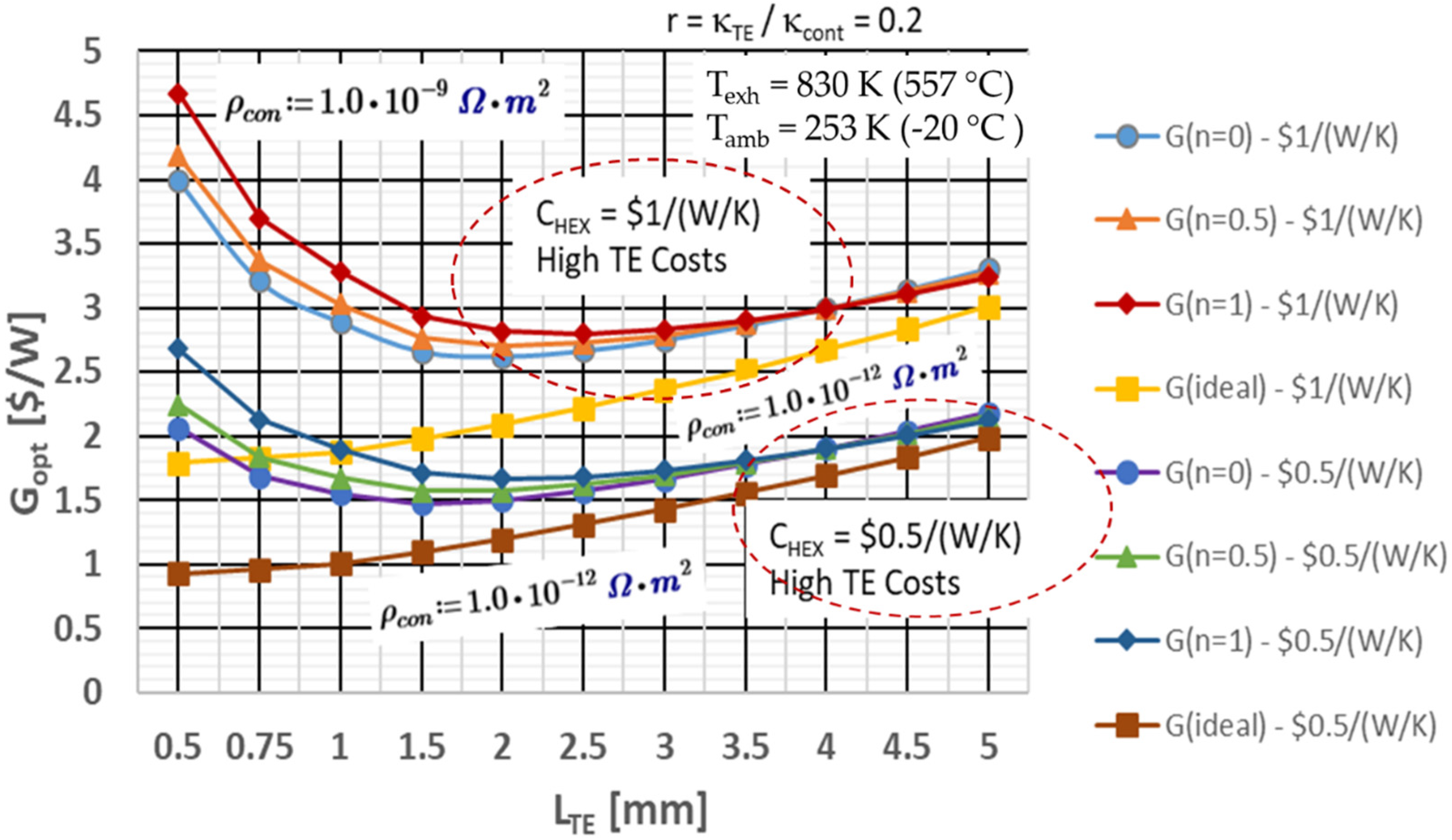
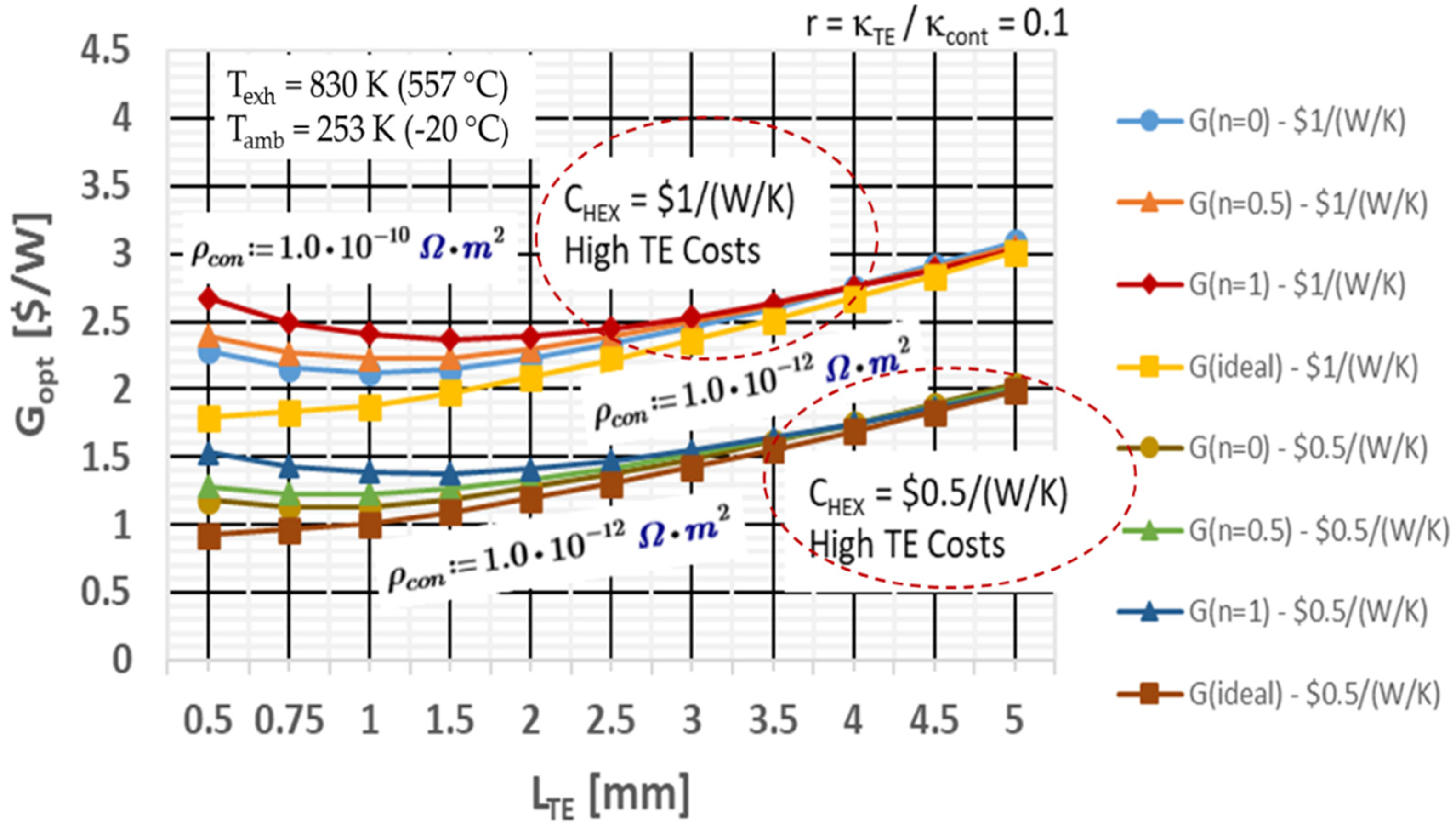
4.2. Thermal and Electrical Contact Resistance Effects on TEG Cost-Performance Optimization

Thermal and electrical interface design and performance, and their impact on TEG system performance, is inherently and intimately tied to TE manufacturing costs. Higher manufacturing costs to create and reproduce high-performance thermal and electrical interfaces can directly lead to higher TEG system performance. The question is how much manufacturing cost is sufficient and what manufacturing cost threshold does one want to incur or absorb to attain that higher performance. The TEG system cost-performance analysis technique discussed herein can be adapted to address this question. In this aspect of work, one can generally include thermal and electrical contact resistance effects by analyzing r ≠ 0 and ρcon ≠ 0 conditions using Equations (3) and (4). One can use generally recognized values for these quantities [139,141,143,144,145,146] to explore design sensitivities, critical design challenges, and potential design barriers to achieving cost-effective TEG systems.
TE manufacturing costs are generally dependent on many factors, with one of the major specific drivers being TE element lengths used in any particular design because in any optimized TE device design the TE element area (therefore element interface area) is coupled to the TE element length. TE manufacturing techniques that are relatively straight-forward, reproducible, and cost effective at one length can be fraught with uncertainty, difficult if not impossible to use in a process flow, and create questionable reproducibility at smaller lengths; due to handling issues, electrical interface control issues, bonding and adhesion issues, and fundamental material structural stress issues, just to name a few. The impact on TE manufacturing costs can be problematic to quantify and hard to project and allocate to system-level cost impacts. As one tries to bound and quantify TE element length effects on manufacturing costs in order at least to estimate trends and impacts, one can hypothesize that the manufacturing cost parameter in this study is mathematically influenced by TE element length. A parametric mathematical approach was implemented using the relationship given Equation (7) below to estimate length effects and establish quantifiable bounds and impacts of TE element-length-induced variations in manufacturing costs at the TEG system-level:
C * = C ( L T E 0.004   m ) n
The fundamental cost parameter C” (i.e., manufacturing costs per TE element area) is customized as inversely proportional to a normalized TE length term to the nth power, where n can be regarded as a cost influence factor. If n = 0, then TE element length has no influence or impact on TE manufacturing costs. If n > 0 and increases, TE element length will have an increasing impact (influence) on TE manufacturing cost as TE element length decreases. If n < 0, then TE element length has an increasing impact on TE manufacturing cost as TE element length increases. Many manufacturing processes could be characterized directly or indirectly by some unique value of n, which could be determined by detailed cost analyses of any given manufacturing process. The length term is arbitrarily normalized by 0.004 m as this is a TE length where current TE processes are well suited, well-understood and repeatable to the point that it is a good reference length to form a basis for conclusions about cost effects. Other reference length values can be chosen to evaluate sensitivities in specific applications, but this value is used here to demonstrate the parametric technique and effects on TEG designs and TEG system-level costs. Equation (7) was implemented to obtain the aforementioned objective to explore design and cost sensitivities of thermal and electrical contact interface performance, resulting critical design challenges, and potential design barriers to achieving cost-effective TEG systems.
The analysis assumptions used herein were basically the same conditions as in the previous Section 4.1 discussing high hot-side heat flux impacts on TEG system costs. Additionally, based on work of Min and Rowe [139,143] with commercial TE devices, the thermal interface performance and design parameter r was set at r = 0.1 and 0.2. The thermal contact layer thickness, lc, was assumed to be 0.25 mm in this work, which is consistent with common layer thicknesses for Jet Propulsion Laboratory materials. Electrical contact resistances investigated were found from work by Caillat et al. [141], Bjørk [144], Ouyang et al. [145] and Ziolkowski [146] and ρcon levels investigated varied from 1.0 × 10⁻⁹ Ω-m2 to 1.0 × 10⁻¹² Ω-m2. A ρcon = 1.0 × 10⁻⁸ to 1.0 × 10⁻⁹ Ω-m2 is considered a generally reproducible achievable level by today’s manufacturing standards, while ρcon = 1.0 × 10⁻¹² Ω-m2 is considered a near-ideal level very difficult to reproducibly achieve with current manufacturing processes.
The modified cost-performance relationship, Equation (4), is now expanded to include the impact of thermal and electrical contact resistances on cost-performance optimization as discussed in Hendricks [11]. The new cost-performance relationship now allows one to account for small TE element height cases (<2 mm), where thermal and electrical contact resistances then become more dominant in the thermal and electrical circuits of the TEG design. An initial sensitivity analysis of Hendricks [134] determined the impact on overall TEG system cost from variation in TE element height, LTE, across a range of LTE from 0.5 mm to 5 mm, while simultaneously accounting for LTE impacts on TE manufacturing costs through Equation (7) discussed above. This is a new and unique utilization of the Gopt relationship initially discussed by Hendricks [6,7].
Figure 20 exhibits results of this TEG system cost-performance sensitivity study for a thermal interface contact resistance parameter, n = 0.2, a nominal value found by Min and Rowe [139,143] for commercial TE devices. The (Gopt, LTE) results are shown plotted for 3 different values of n in Equation (7) (i.e., 0, 0.5, and 1), two different CHEX values and the range of ρcon varied from 1.0 × 10⁻⁹ Ω-m2 to 1.0 × 10⁻¹² Ω-m2. These results demonstrate for a realistic value of ρcon = 1.0 × 10⁻⁹ Ω-m2 that driving toward low LTE first leads to an optimum-cost LTE, and then increasing the Gopt with further decreasing LTE as electrical contact resistance (resistivity) effects become more dominant in controlling and reducing TEG power output. The Gopt increases dramatically as these electrical contact resistances (resistivities) dominate the TEG system cost picture. It is crucial to realize in Figure 20 that there does exist an optimum cost LTE even if manufacturing costs are not sensitive to LTE at all (i.e., n = 0 cases).
When the electrical contact resistance decreases to near-ideal conditions with ρcon = 1.0 × 10⁻¹² Ω-m2, then and only then does Gopt decrease asymptotically as LTE decreases. This asymptotic behavior in Gopt as LTE decreases is what early investigations by Yee et al. [136] found when they too neglected electrical and thermal interface contact resistance effects and did not account for heat exchanger cost-performance effects. This work now shows a more comprehensive and more complete picture of the (Gopt, LTE) relationship and that a true optimum-cost LTE does exist for different manufacturing cost sensitivities in TEG energy recovery systems.
Figure 20 also demonstrates the strong impact that heat exchanger costs have on TEG system costs as heat exchanger costs, CHEX, vary from $0.5/(W/K) to $1/(W/K). It does not shift where the optimum cost LTE occurs too much, but higher CHEX case ($1/(W/K) increases TEG system costs by almost 2 times at optimum cost LTE points. A major point to make regarding these results is just the absolute magnitude of the Gopt values when the heat exchanger costs get too high at $1/(W/K); even at optimum cost LTE points the Gopt is > $2.5/W and increases substantially at low LTE values. This is well above the reference comparative value established for competitive energy recovery power systems and simply not a competitive cost level for TEG systems in energy recovery applications. Once again demonstrating the absolute critical importance of heat exchanger costs in driving the TEG system commercialization potential in energy recovery [6,7,134]. Heat exchanger costs of $0.5/(W/K) produce TEG system costs closer to $1.5/W in this analysis, which is more competitive with other energy conversion systems. It is obvious that low heat exchanger costs, low electrical interface contact resistivities, and optimum cost LTE are the critical keys—all three are required to achieve cost-competitive TEG systems.
Figure 20 also shows the TE manufacturing cost sensitivity to LTE in Equation (7) influences the TEG system cost level and where the optimum cost LTE actually occurs. As TE manufacturing costs are more sensitive to LTE, then optimum TEG costs tend to increase. Simultaneously, the optimum cost LTE increases such that the TEG system design would like larger TE element heights as n increases from 0 (no LTE impact on TE manufacturing costs) to n = 1 (much stronger LTE impact on TE manufacturing costs). In this analysis, the optimum cost LTE increases from approximately 1.5 mm to 2.5 mm as n increases from 0 to 1 for either heat exchanger cost condition, generally showing that TE element lengths must be closer to the reference LTE value as costs become more sensitive to LTE. This is generally due to TE manufacturing costs reducing more in n = 1 cases, and thereby allowing TE element dimensions to increase in the optimum cost designs. This magnitude of change in optimum cost LTE has a dramatic effect on the overall TEG system design, thereby demonstrating the importance of LTE influences on manufacturing costs in dictating optimum TEG system costs. Although slightly counterintuitive, one must realize [$/W] is critical here and this result highlights the paradigm that thermal and electrical interface performances are controlling design parameters when thermal or electrical contact resistances are too high.
A final note is apparent from Figure 20. It is clear implementing thermal interface and electrical interface contact resistances that are commonly quoted [139,141,142,143,145] does not necessarily create cost-competitive, cost-effective TEG systems. This is one explanation that tends to illuminate why TEG systems are commonly regarded and viewed as expensive. This highlights the TEG design challenges to surmount and the new TE design paradigms that must be adopted to achieve or even come close to achieving a more competitive $1/We for TEG energy recovery designs.
Additional cost-performance analyses were performed for a lower thermal interface contact resistance parameter, r = 0.1, and a lower electrical interface contact resistivity (resistance), ρcon = 1.0 × 10⁻¹⁰ Ω-m2, to better quantify and understand the magnitude of contact resistance effects in the TEG system cost optimization. The purpose here was to quantify what thermal and electrical interface resistance performance levels would be necessary to achieve a TEG cost metric of near ~$1/W. Figure 21 shows the results of the analysis and how much-higher-performance thermal and electrical interfaces can decrease the TEG system cost ($/W) from that shown in Figure 20. The TEG system cost is near ~$2.25/W at cost optimum LTE points when heat exchanger costs are $1/(W/K) and with high TE material and manufacturing costs. The TEG system cost reduces further approaching $1/W when heat exchanger costs are decreased to $0.5/(W/K) for the high-performance thermal and electrical contact resistance conditions (r = 0.1 and ρcon = 1.0 × 10⁻¹⁰ Ω-m2). It is noteworthy that this work shows these levels of thermal contact resistance and electrical contact resistance appear sufficient to approach the critical TEG system cost level of $1/W. The electrical interface contact resistance characterized by ρcon = 1.0 × 10⁻¹⁰ Ω-m2 creates TEG cost results that are, in many cases, close to results at near-ideal electrical contact resistance conditions characterized by ρcon = 1.0 × 10⁻¹² Ω-m2. This once again shows that low heat exchanger costs, low electrical interface contact resistivities, and optimum cost LTE are the critical keys (all three required) to achieve competitive TEG system costs approaching $1/W.
Figure 21 results also demonstrate the same behavior in TEG system costs as a function of TE element height, LTE, and dependence of TE manufacturing costs on LTE as in Figure 20 results. The important difference however is that the optimum cost LTE occurs at lower values for these cases with higher-performance thermal and electrical contact resistance performance. Once again Figure 21 results also demonstrate (as in Figure 20) that there does exist an optimum cost LTE even if manufacturing costs are not sensitive to LTE at all (i.e., n = 0 cases). In the $1/(W/K) heat exchanger case, the optimum cost LTE varies between 1.0 mm to 1.75 mm depending on the level of sensitivity to LTE one assumes on the TE manufacturing costs. In the $0.5/(W/K) heat exchanger case, the optimum cost LTE varies between 1.0 mm and 1.5 mm depending on what level of sensitivity to LTE one assumes on the TE manufacturing costs. As in Figure 20 results, the optimum TEG cost increases and the optimum-cost LTE increases to the higher value in the quoted range as TE manufacturing costs are more sensitive to decreasing LTE (n = 1 case vs. n = 0 case). Sensitivity of TE manufacturing costs to TE element height LTE once again having an important impact on optimum cost LTE and thereby the TEG system design.
It is also crucial to realize in Figure 21 results that, once thermal and electrical contact resistance effects are lowered to these levels, then the heat exchanger costs actually dominate and create the largest reduction in TEG system costs. The sensitivity to TE manufacturing cost dependence on LTE also diminishes significantly as the relationships for n = 0 and n = 1 are tending to collapse on one another. This effect definitely benefits the TE system design and provides more flexibility in TE system cost-performance tradeoffs, which is helpful given the TE system’s strong dependence on heat exchanger costs and performance in these cases.
Figure 21 results underscore the power and utility of Equation (4) relationship for Gopt when trying to discern and differentiate the “impact magnitude” of the many TE materials costs, TE manufacturing costs, heat exchanger costs and performance, hot-side heat flux, and TE design parameters on TEG system costs. Equations (3) and (4) provide a more complete and comprehensive picture of the complex design tradeoffs. The lack of capability to discern and differentiate prior to this work has been a severe barrier to TEG system commercialization up to now because the TE community has not known where and how to focus their design and research and development thrusts. This work definitely demonstrates that true TEG system cost-performance optimization is not only dependent on the TE materials and their TE properties, but rather a complex mosaic of interdependent thermal and TE design behavior and phenomenon. Equations (3) and (4) helps us to better understand the mosaic, how to manipulate it, and elucidate the interdependencies.
Figure 21. Decreased Electrical and Thermal Contact Interface Effects on Overall TEG Cost Minimization for Various Heat Exchanger Cost Parameters and Cost Sensitivities to TE Manufacturing Costs (r = 0.1).
Energies 15 07307 g021
This work was performed using SKD TE material properties. However, the analysis shown here could easily be applied to any of the TE materials discussed in Section 2 and Section 3 using the mathematics and techniques presented herein. The behaviors and interdependences discussed herein would be similar, although the exact numerical results will differ. Further research in TSE with other TE materials is strongly recommended.

5. Conclusions

Development of thermoelectric materials and modules is important as power generation for waste-heat energy-saving and IoT sensors. The performance, i.e., conversion efficiency and maximum output power, of both materials and modules are critical for the applicative success.
Here, in this review, first of all, we have reviewed some recent trends in material development. Namely, the development of various enhancement principles for increase in the Seebeck coefficient/power factor and selective reduction in thermal conductivity. In particular we have focused on the renewed interest to utilize magnetism to enhance the Seebeck coefficient, e.g., magnon drag, paramagnon drag, spin fluctuation, spin entropy. We have also selected several low thermal conductivity principles like utilization of materials informatics, heterogeneous bonds, and large lattice softening effect via doping. Defect engineering is a principle in various forms which has exhibited recent successes to achieve particular high performance in some new materials. We have also reviewed the progress in development of SKDs, and recent focused new materials like lead-free GeTe, SnTe, and relatively abundant, and just about Te-free Mg3(Sb,Bi)2-type in particular as a promising and long awaited Bi2Te3 replacement material candidate.
This review has also highlighted and discussed the fundamentals of thermoelectric systems economics (TSE) as applied to high-power thermoelectric energy recovery applications. Several new paradigms are evident from this work. TE system economics and cost is often the controlling and determining discriminator in the final business decision to implement a TE energy recovery system. High-power TE systems must be close to $1/We to be cost-competitive with other energy recovery and conversion systems, like Rankine-based systems, Organic-Rankine systems, geothermal power systems, and solar systems in solar system applications.
First, TSE analyses have demonstrated that cost-competitive, cost-effective high-power TE systems must have high TE fill-factors, Fopt ≥ 0.65; much higher than commonly implemented in current TE device and system design. This will require a major design paradigm shift in TE design thinking, but this is similar to what has been successfully solved and implemented in successful, cost-competitive solar cell and solar array designs in the solar industry today. Second, the TSE analyses have also highlighted and emphasized the importance of hot-side and cold-side heat exchanger costs in often controlling and dominating the overall TE system economic costs. Heat exchanger costs are critically important and this work has demonstrated cost-effective, cost-competitive TE systems in energy recovery applications must either have: (1) high hot-side heat fluxes and this work has shown >15 W/cm2 as a critical level to achieve, or (2) the heat exchangers must be very low cost (<$0.25/(W/K)) or essentially “free” to the TE system in any particular energy recovery application.
The TSE analysis and modeling has now been upgraded to include the critical effects of thermal and electrical contact resistance. This new capability has demonstrated that cost-effective, cost-competitive TE systems require optimum TE element lengths, LTE, to minimize cost per watt metrics. These optimum TE element lengths are impacted greatly by TE element manufacturing cost sensitivities to the TE element length. New techniques have been developed and presented herein that allow the TE system designer to evaluate and determine optimum TE element lengths leading to cost-effective, cost-competitive TE system designs. How TE element lengths actually impact TE system costs depends on how TE element dimensions (i.e., length and wide or radius dimension) impact the TE manufacturing costs. The techniques demonstrated herein allow the TE system design to evaluate a variety of scenarios; increasing LTE reducing TE manufacturing costs or increasing LTE increasing TE manufacturing costs. The reader is referred to Section 4.2 for the details on this topic.
Finally, TSE analyses have demonstrated that low thermal and electrical contact resistances are also required to produce cost-effective, cost-competitive high-power TE systems for energy recovery applications. This work generally demonstrated that electrical contact resistances <1.0 × 10⁻⁹ ohm-m2 in concert with low heat exchanger costs are required to create cost-competitive, high-power TE systems with costs approaching $1/W. This is once again a new design paradigm for cost-competitive, high-power TE systems, as this low level of electrical contact resistance or lower is extremely difficult to achieve. Future research is required in this technical area to help high-power TE systems achieve their full potential in energy recovery applications.

Author Contributions

Introduction 1.0, T.H., T.C. and T.M.; Advances in Thermoelectric Materials and Methods 2.0. T.M. and T.C.; Advances in Thermoelectric Device Design and Fabrication, 3.0. T.M., T.C. and T.H.; Thermoelectric System Economics, 4.0., T.H.; Conclusions, 5.0 T.M., T.C. and T.H.; data curation, T.H., T.C. and T.M.; writing—original draft preparation, T.H., T.C. and T.M.; writing—review and editing, T.H., T.C. and T.M.; visualization, T.H., T.C. and T.M.; supervision, T.H., T.C. and T.M.; article administration, T.H. All authors have read and agreed to the published version of the manuscript.

Funding

This work was partially funded by the NASA Radioisotope Power Systems program. T.M. acknowledges support from JST Mirai Program JPMJMI19A1.

Acknowledgments

T.M. thanks past and present members of JST Mirai Large-Scale Program; N. Tsujii, I. Ohkubo, J. Shuai, Z. Liu, C-H. Lee, B. Srinivasan, W. Zhang, N. Sato for providing figures. Wenhao Zhang is thanked for providing technical help regarding the references. Some of this work was carried out under NASA Prime contract NNN12AA01C, at the Jet Propulsion Laboratory, California Institute of Technology, under a contract to the National Aeronautics and Space Administration (NASA).

Conflicts of Interest

The authors declare no conflict of interest. The funders had no role in the design of the study; in the collection, analyses, or interpretation of data; in the writing of the manuscript, or in the decision to publish the results.

Nomenclature

English
AHEXTE/Heat Exchanger Interface Area [m2]
ATEThermoelectric Element Area [m2]
CTEGThermoelectric Generator Cost [$]
CHEXHeat Exchanger Cost Parameter [$/(W/K)]
𝐶′′TE System Manufacturing/Fabrication Costs per Area [$/m2]
𝐶′′′TE Material Volumetric Costs per Volume [$/m3]
CpExhaust Flow Specific Heat [J/kg-K]
fQThermal Interface Function (Equation (2))
FFill Factor
FoptOptimum Cost Fill Factor
GThermoelectric System Cost per Watt [$/W]
GoptOptimum Thermoelectric System Cost at Fopt [$/W]
IThermoelectric Device Current [A]
KexhHeat Exchanger Conductance [W/K]
KHHot Side Total Thermal Conductance [W/K]
KCCold Side Total Thermal Conductance [W/K]
KHXHeat Exchanger Conductance Value [W/K]
KTEEffective Thermoelectric Conductance [W/K]
lcThickness of thermal contact layer [m]
LThermoelectric Element Length [m]
mLoad resistance to TE device resistance ratio
m ˙ h Exhaust mass flow rate [kg/sec]
NNumber of Thermoelectric Couples
nCost influence factor in Equation (4–5)
qThermal Flux [W/m2]
QThermal Transfer on Hot- or Cold-Side [W]
rThermal Interface Contact Parameter—Thermal Conductivity Ratio [κTEcon]
SpnTotal Seebeck Coefficient (= Sp + |Sn|) [V/K]
UAuHeat Exchanger UA Value [W/K]
VThermoelectric Device Voltage [V]
TTemperature [K]
ZTFigure of merit (dimensionless)
ZTavAverage Figure of merit (dimensionless)
Greek
ΔT(Texh − Tamb) [K]
εHeat Exchanger Thermal Effectiveness
γThermoelectric Element Length to Area Ratio [m−1]
κThermal Conductivity (thermoelectric material unless otherwise specified) [W/m/K]
ηThermoelectric Conversion Efficiency
ρconElectrical Contact Resistivity [Ohm − m2]
ρaveAverage Electrical Resistivity of p-type and n-type TE materials [Ohm − m]
σElectrical Conductivity [S/m]
Subscripts
ambambient environment
concontact interface
exhexhaust conditions
h or HAssociated with TE hot-side parameter
c or CAssociated with TE cold-side parameter
nAssociated with TE n-type materials
pAssociated with TE p-type materials
TEThermoelectric parameter
HEXHeat Exchanger parameter

References

  1. Bell, L.E. Cooling, heating, generating power, and recovering waste heat with thermoelectric systems. Science 2008, 321, 1457–1461. [Google Scholar] [CrossRef] [PubMed] [Green Version]
  2. Mori, T.; Priya, S. Materials for energy harvesting: At the forefront of a new wave. MRS Bull. 2018, 43, 176–180. [Google Scholar] [CrossRef] [Green Version]
  3. Champier, D. Thermoelectric generators: A review of applications. Energy Convers. Manag. 2017, 140, 167–181. [Google Scholar] [CrossRef]
  4. Tan, G.; Ohta, M.; Kanatzidis, M.G. Thermoelectric power generation: From new materials to devices. Philos. Trans. R. Soc. A 2019, 377, 20180450. [Google Scholar] [CrossRef] [PubMed] [Green Version]
  5. Mori, T. Perspectives of high-temperature thermoelectric applications and p-type and n-type aluminoborides. JOM 2016, 68, 2673–2679. [Google Scholar] [CrossRef]
  6. Hendricks, T.J. Thermoelectric system economics: Where the laws of thermoelectrics, thermodynamics, heat transfer and economics intersect. MRS Adv. 2019, 4, 457–471. [Google Scholar] [CrossRef]
  7. Hendricks, T.J. New paradigms in defining optimum cost conditions in thermoelectric energy recovery designs. Mater. Today Proc. 2019, 8, 613–624. [Google Scholar] [CrossRef]
  8. Miller, E.W.; Hendricks, T.J.; Wang, H.; Peterson, R.B. Integrated dual-cycle energy recovery using thermoelectric conversion and an organic rankine bottoming cycle. Proc. Inst. Mech. Eng. Part A J. Power Energy 2011, 225, 33–43. [Google Scholar] [CrossRef]
  9. Wang, H.; Hendricks, T.; Krishnan, S. Experimental validation of a portable power and cooling system using integrated TEG-ORC. J. Thermophys Heat Transf. 2021, 35, 411–420. [Google Scholar] [CrossRef]
  10. Petsagkourakis, I.; Tybrandt, K.; Crispin, X.; Ohkubo, I.; Satoh, N.; Mori, T. Thermoelectric taterials and applications for energy harvesting power generation. Sci. Technol. Adv. Mater. 2018, 19, 836–862. [Google Scholar] [CrossRef] [PubMed] [Green Version]
  11. Haras, M.; Skotnicki, T. Thermoelectricity for IoT—A review. Nano Energy 2018, 54, 461–476. [Google Scholar] [CrossRef]
  12. Tarancón, A. Powering the IoT revolution with heat. Nat. Electron. 2019, 2, 270–271. [Google Scholar] [CrossRef]
  13. Nandihalli, N.; Liu, C.-J.; Mori, T. Polymer based thermoelectric nanocomposite materials and devices: Fabrication and characteristics. Nano Energy 2020, 78, 105186. [Google Scholar] [CrossRef]
  14. Soleimani, Z.; Zoras, S.; Ceranic, B.; Cui, Y.; Shahzad, S. A comprehensive review on the output voltage/power of wearable thermoelectric generators concerning their geometry and thermoelectric materials. Nano Energy 2021, 89, 106325. [Google Scholar] [CrossRef]
  15. Sootsman, J.; Young Chung, D.; Kanatzidis, M.G. New and old concepts in thermoelectric aaterials. Angew. Chem. Int. Ed. 2009, 48, 8616–8639. [Google Scholar] [CrossRef]
  16. He, J.; Tritt, T.M. Advances in thermoelectric materials research: Looking back and moving forward. Science 2017, 357, eaak9997. [Google Scholar] [CrossRef] [PubMed] [Green Version]
  17. Zhu, T.; Liu, Y.; Fu, C.; Heremans, J.P.; Snyder, J.G.; Zhao, X. Compromise and synergy in high-efficiency thermoelectric materials. Adv. Mater. 2017, 29, 1605884. [Google Scholar] [CrossRef] [PubMed]
  18. Mori, T. Novel principles and nanostructuring methods for enhanced thermoelectrics. Small 2017, 13, 1702013. [Google Scholar] [CrossRef] [PubMed] [Green Version]
  19. Mao, J.; Liu, Z.; Zhou, J.; Zhu, H.; Zhang, Q.; Chen, G.; Ren, Z. Advances in thermoelectrics. Adv. Phys. 2018, 67, 69–147. [Google Scholar] [CrossRef]
  20. Garmroudi, F.; Riss, A.; Parzer, M.; Reumann, N.; Müller, H.; Bauer, E.; Khmelevskyi, S.; Podloucky, R.; Mori, T.; Tobita, K.; et al. Boosting the thermoelectric performance of Fe2VAl−type Heusler compounds by band engineering. Phys. Rev. B Condens. Matter 2021, 103, 085202. [Google Scholar] [CrossRef]
  21. Fu, C.; Zhu, T.; Liu, Y.; Xie, H.; Zhao, X. Band engineering of high performance p-type FeNbSb based half-heusler thermoelectric materials for figure of merit ZT > 1. Energy Environ. Sci. 2015, 8, 216–220. [Google Scholar] [CrossRef]
  22. Heremans, J.P.; Jovovic, V.; Toberer, E.S.; Saramat, A.; Kurosaki, K.; Charoenphakdee, A.; Yamanaka, S.; Snyder, G.J. Enhancement of thermoelectric efficiency in PbTe by distortion of the electronic density of states. Science 2008, 321, 554–557. [Google Scholar] [CrossRef] [PubMed] [Green Version]
  23. Pei, Y.; Shi, X.; LaLonde, A.; Wang, H.; Chen, L.; Snyder, G.J. Convergence of electronic bands for high performance bulk thermoelectrics. Nature 2011, 473, 66–69. [Google Scholar] [CrossRef] [PubMed] [Green Version]
  24. Wang, H.; Pei, Y.; LaLonde, A.D.; Snyder, G.J. Material design considerations based on thermoelectric quality factor. In Thermoelectric Nanomaterials; Koumoto, K., Mori, T., Eds.; Springer: Berlin/Heidelberg, Germany, 2013; pp. 3–32. [Google Scholar]
  25. Shakouri, A.; LaBounty, C.; Abraham, P.; Piprek, J.; Bowers, J.E. Enhanced thermionic emission cooling in high barrier superlattice heterostructures. MRS Proc. 1998, 545. [Google Scholar] [CrossRef] [Green Version]
  26. Bailyn, M. Maximum variational principle for conduction problems in a magnetic field, and the theory of magnon drag. Phys. Rev. 1962, 126, 2040–2054. [Google Scholar] [CrossRef]
  27. Bailyn, M. Transport in Metals: Effect of the Nonequilibrium Phonons. Phys. Rev. 1958, 112, 1587–1598. [Google Scholar] [CrossRef]
  28. Klemens, P.G. The contribution of phonons to the thomson coefficient. Aust. J. Phys. 1954, 7, 520. [Google Scholar] [CrossRef]
  29. Ang, R.; Khan, A.U.; Tsujii, N.; Takai, K.; Nakamura, R.; Mori, T. Thermoelectricity generation and electron–magnon scattering in a natural chalcopyrite mineral from a deep-sea hydrothermal vent. Angew. Chem. Int. Ed. 2015, 54, 12909–12913. [Google Scholar] [CrossRef] [PubMed]
  30. Matsuura, H.; Ogata, M.; Mori, T.; Bauer, E. Theory of huge thermoelectric effect based on a magnon drag mechanism: Application to thin-film heusler alloy. Phys. Rev. B Condens. Matter 2021, 104, 214421. [Google Scholar] [CrossRef]
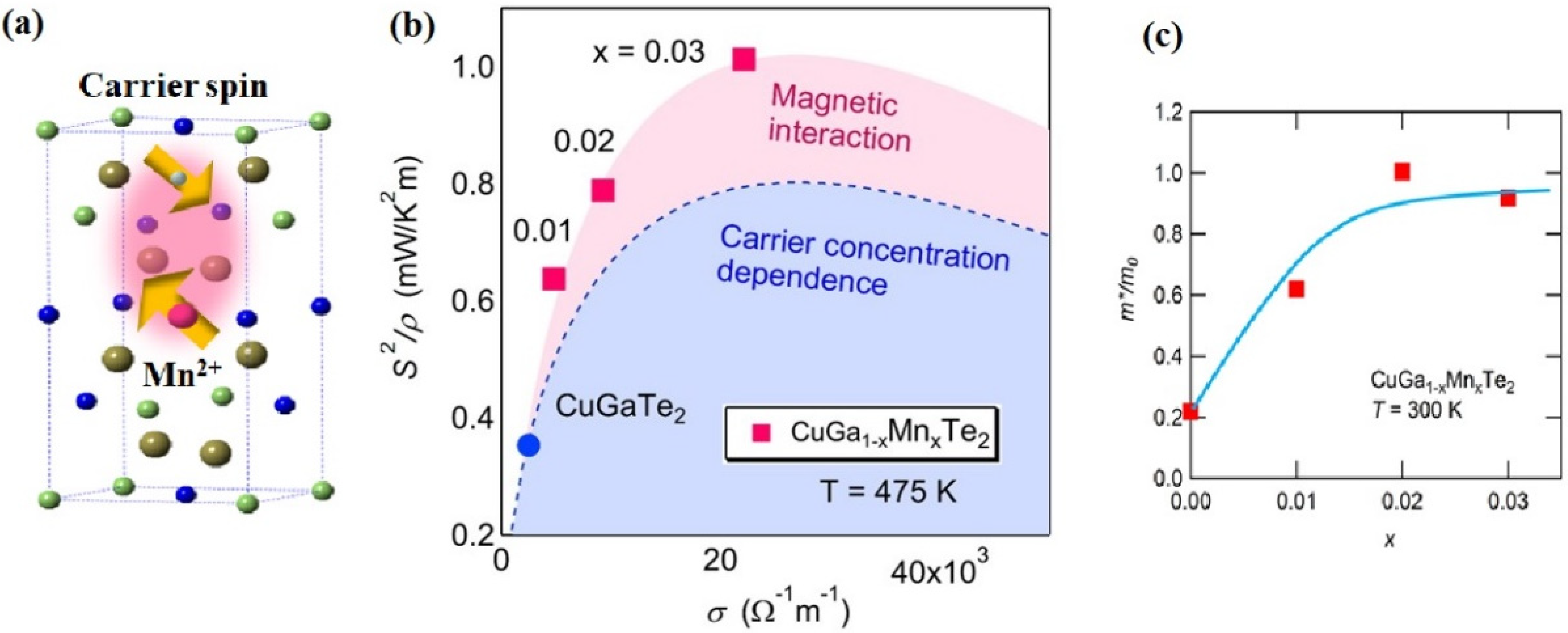
  31. Ahmed, F.; Tsujii, N.; Mori, T. Thermoelectric properties of CuGa1−xMnxTe2: Power factor enhancement by incorporation of magnetic ions. J. Mater. Chem. A 2017, 5, 7545–7554. [Google Scholar] [CrossRef]
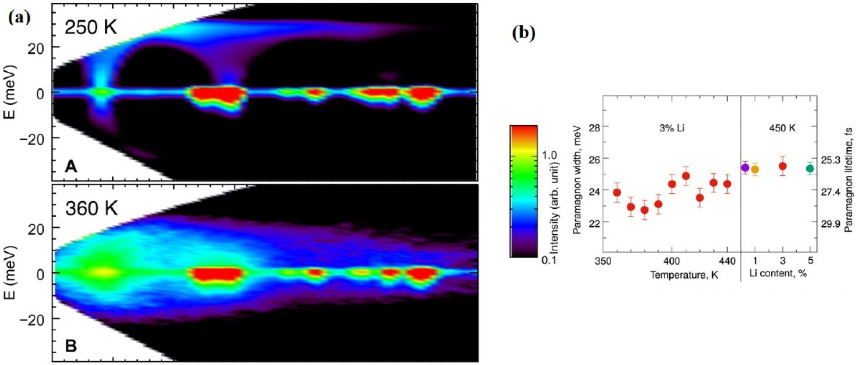
  32. Zheng, Y.; Lu, T.; Polash, M.M.H.; Rasoulianboroujeni, M.; Liu, N.; Manley, M.E.; Deng, Y.; Sun, P.J.; Chen, X.L.; Hermann, R.P.; et al. Paramagnon drag in high thermoelectric figure of merit Li-doped MnTe. Sci. Adv. 2019, 5, eaat9461. [Google Scholar] [CrossRef] [PubMed] [Green Version]
  33. Vaney, J.-B.; Yamini, S.A.; Takaki, H.; Kobayashi, K.; Kobayashi, N.; Mori, T. Magnetism-mediated thermoelectric performance of the Cr-doped bismuth telluride tetradymite. Mater. Today Phys. 2019, 9, 100090. [Google Scholar] [CrossRef]
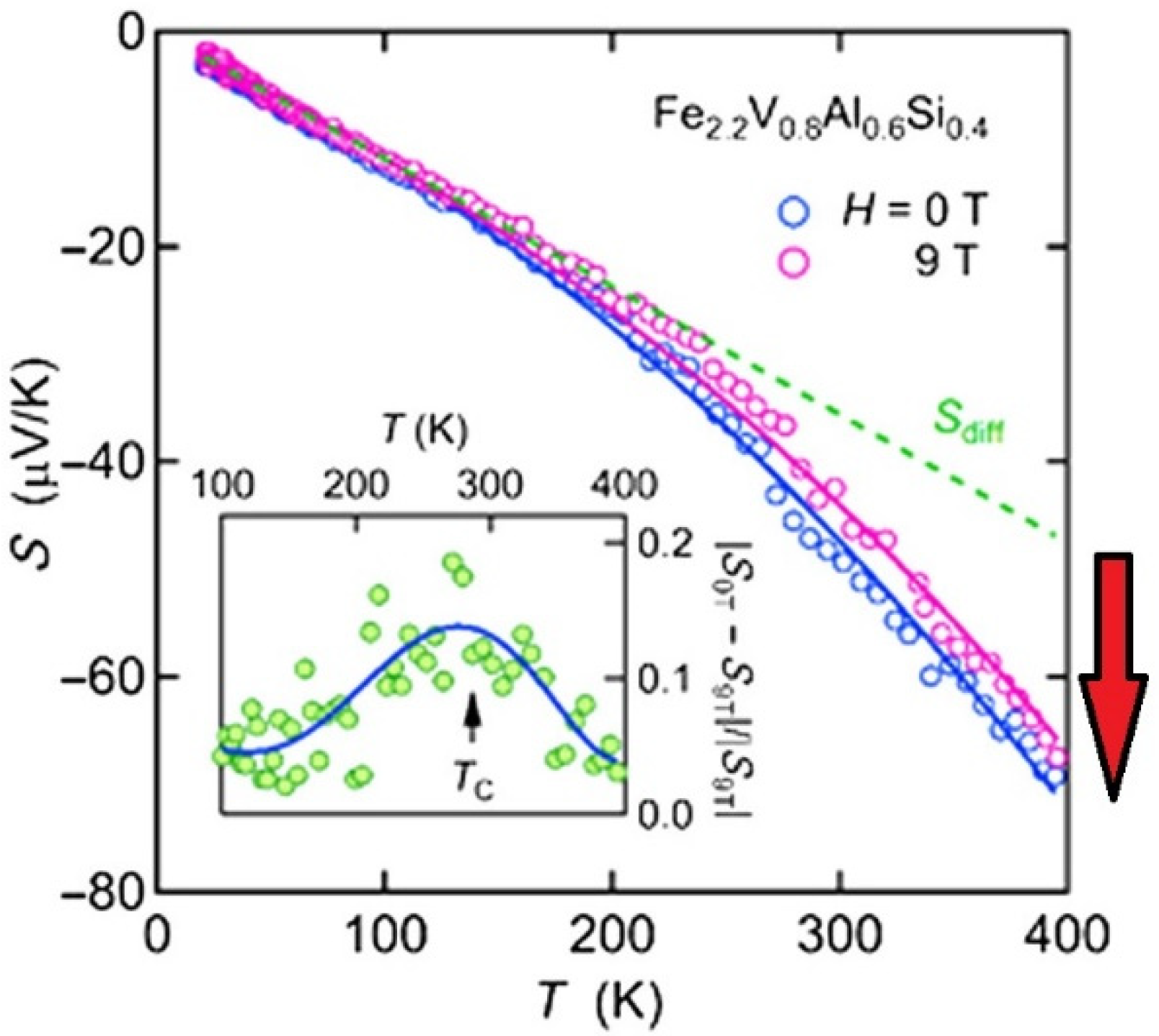
  34. Tsujii, N.; Nishide, A.; Hayakawa, J.; Mori, T. Observation of enhanced thermopower due to spin fluctuation in weak itinerant ferromagnet. Sci. Adv. 2019, 5, eaat5935. [Google Scholar] [CrossRef] [Green Version]
  35. Zhao, W.; Liu, Z.; Sun, Z.; Zhang, Q.; Wei, P.; Mu, X.; Zhou, H.; Li, C.; Ma, S.; He, D.; et al. Superparamagnetic enhancement of thermoelectric performance. Nature 2017, 549, 247–251. [Google Scholar] [CrossRef] [PubMed]
  36. Zhao, W.; Liu, Z.; Wei, P.; Zhang, Q.; Zhu, W.; Su, X.; Tang, X.; Yang, J.; Liu, Y.; Shi, J.; et al. Magnetoelectric interaction and transport behaviours in magnetic nanocomposite thermoelectric materials. Nat. Nanotechnol. 2016, 12, 55–60. [Google Scholar] [CrossRef] [PubMed] [Green Version]
  37. Du, B.; Lai, X.; Liu, Q.; Liu, H.; Wu, J.; Liu, J.; Zhang, Z.; Pei, Y.; Zhao, H.; Jian, J. Spark plasma sintered bulk nanocomposites of Bi2Te2.7Se0.3 nanoplates incorporated Ni nanoparticles with enhanced thermoelectric performance. ACS Appl. Mater. Interfaces 2019, 11, 31816–31823. [Google Scholar] [CrossRef]
  38. Pei, J.; Dong, J.; Cai, B.; Zhang, Y.; Zhou, W.; Zhang, B.-P.; Ge, Z.-H.; Li, J.-F. Weak-ferromagnetism for room temperature thermoelectric performance enhancement in p-Type (Bi,Sb)2Te3. Mater. Today Phys. 2021, 19, 100423. [Google Scholar] [CrossRef]
  39. Terasaki, I.; Sasago, Y.; Uchinokura, K. Large thermoelectric power in NaCo2O4 single crystals. Phys. Rev. B Condens. Matter. 1997, 56, R12685–R12687. [Google Scholar] [CrossRef]
  40. Koshibae, W.; Tsutsui, K.; Maekawa, S. Thermopower in cobalt oxides. Phys. Rev. B Condens. Matter 2000, 62, 6869–6872. [Google Scholar] [CrossRef]
  41. Sussardi, A.; Tanaka, T.; Khan, A.U.; Schlapbach, L.; Mori, T. Enhanced thermoelectric Properties of samarium boride. J. Mater. 2015, 1, 196–204. [Google Scholar] [CrossRef]
  42. Hébert, S.; Daou, R.; Maignan, A.; Das, S.; Banerjee, A.; Klein, Y.; Bourgès, C.; Tsujii, N.; Mori, T. Thermoelectric materials taking advantage of spin entropy: Lessons from chalcogenides and oxides. Sci. Technol. Adv. Mater. 2021, 22, 583–596. [Google Scholar] [CrossRef] [PubMed]
  43. Acharya, S.; Anwar, S.; Mori, T.; Soni, A. Coupling of charge carriers with magnetic entropy for power factor enhancement in Mn doped Sn1.03Te for thermoelectric applications. J. Mater. Chem. C 2018, 6, 6489–6493. [Google Scholar] [CrossRef]
  44. Chang, H.; Gui, X.; Huang, S.; Nepal, R.; Chapai, R.; Xing, L.; Xie, W.; Jin, R. Mn-induced ferromagnetism and enhanced thermoelectric properties in Ru1−xMnxSb2+δ. New J. Phys. 2019, 21, 033008. [Google Scholar] [CrossRef]
  45. Li, C.; Ma, S.; Wei, P.; Zhu, W.; Nie, X.; Sang, X.; Sun, Z.; Zhang, Q.; Zhao, W. Magnetism-induced huge enhancement of the room-temperature thermoelectric and cooling performance of p-type BiSbTe alloys. Energy Environ. Sci. 2020, 13, 535–544. [Google Scholar] [CrossRef]
  46. Fortulan, R.; Yamini, S.A.; Nwanebu, C.; Li, S.; Baba, T.; Reece, M.J.; Mori, T. Thermoelectric performance of n-type magnetic element doped Bi2S3. ACS Appl. Energy Mater. 2022, 5, 3845–3853. [Google Scholar] [CrossRef]
  47. Khan, A.U.; Orabi, R.A.R.A.; Pakdel, A.; Vaney, J.-B.; Fontaine, B.; Gautier, R.; Halet, J.-F.; Mitani, S.; Mori, T. Sb Doping of metallic CuCr2S4 as a route to highly improved thermoelectric properties. Chem. Mater. 2017, 29, 2988–2996. [Google Scholar] [CrossRef]
  48. Shuai, J.; Mao, J.; Song, S.; Zhu, Q.; Sun, J.; Wang, Y.; He, R.; Zhou, J.; Chen, G.; Singh, D.J.; et al. Tuning the carrier scattering mechanism to effectively improve the thermoelectric properties. Energy Environ. Sci. 2017, 10, 799–807. [Google Scholar] [CrossRef]
  49. Wang, H.; Gurunathan, R.; Fu, C.; Cui, R.; Zhu, T.; Snyder, G.J. Thermoelectric transport effects beyond single parabolic band and acoustic phonon scattering. Mater. Adv. 2022, 3, 734–755. [Google Scholar] [CrossRef]
  50. Hu, C.; Xia, K.; Fu, C.; Zhao, X.; Zhu, T. Carrier grain boundary scattering in thermoelectric materials. Energy Environ. Sci. 2022, 15, 1406–1422. [Google Scholar] [CrossRef]
  51. Mori, T.; Hara, T. Hybrid effect to possibly overcome the trade-off between seebeck coefficient and electrical conductivity. Scr. Mater. 2016, 111, 44–48. [Google Scholar] [CrossRef]
  52. Zianni, X. The Annealed-Nanograin Phase: A route to simultaneous increase of the conductivity and the seebeck coefficient and high thermoelectric performance. J. Appl. Phys. 2019, 126, 194301. [Google Scholar] [CrossRef]
  53. Hsu, K.F.; Loo, S.; Guo, F.; Chen, W.; Dyck, J.S.; Uher, C.; Hogan, T.; Polychroniadis, E.K.; Kanatzidis, M.G. Cubic AgPbmSbTe2+m: Bulk thermoelectric materials with high figure of merit. Science 2004, 303, 818–821. [Google Scholar] [CrossRef] [PubMed]
  54. Sootsman, J.; Kong, H.; Uher, C.; Downey, A.; D’Angelo, J.J.; Wu, C.I.; Hogan, T.; Caillat, T.; Kanatzidis, M. Transport Behavior and Thermal Conductivity Reduction in the Composite System PbTe-Pb-Sb; Thermoelectric Power Generation: Boston, MA, USA, 2008; Volume 1044. [Google Scholar]
  55. Wang, X.W.; Lee, H.; Lan, Y.C.; Zhu, G.H.; Joshi, G.; Wang, D.Z.; Yang, J.; Muto, A.J.; Tang, M.Y.; Klatsky, J.; et al. Enhanced thermoelectric figure of merit in nanostructured n-type silicon germanium bulk alloy. Appl. Phys. Lett. 2008, 93, 193121. [Google Scholar] [CrossRef]
  56. Liu, Z.; Mao, J.; Liu, T.-H.; Chen, G.; Ren, Z. Nano-microstructural control of phonon engineering for thermoelectric energy harvesting. MRS Bull. 2018, 43, 181–186. [Google Scholar] [CrossRef] [Green Version]
  57. Liu, Z.; Mori, T. Nanostructured bulk thermoelectric materials for energy harvesting. In System-Materials Nanoarchitectonics; Wakayama, Y., Ariga, K., Eds.; Springer: Tokyo, Japan, 2022; pp. 199–231. [Google Scholar]
  58. Gaultois, M.W.; Oliynyk, A.O.; Mar, A.; Sparks, T.D.; Mulholland, G.J.; Meredig, B. Perspective: Web-based machine learning models for real-time screening of thermoelectric materials properties. APL Mater. 2016, 4, 053213. [Google Scholar] [CrossRef] [Green Version]
  59. Zhang, R.; Chen, K.; Du, B.; Reece, M.J. Screening for Cu–S based thermoelectric materials using crystal structure features. J. Mater. Chem. A 2017, 5, 5013–5019. [Google Scholar] [CrossRef] [Green Version]
  60. Suwardi, A.; Bash, D.; Ng, H.K.; Gomez, J.R.; Repaka, D.V.M.; Kumar, P.; Hippalgaonkar, K. Inertial effective mass as an effective descriptor for thermoelectrics via data-driven evaluation. J. Mater. Chem. A 2019, 7, 23762–23769. [Google Scholar] [CrossRef]
  61. Li, M.; Cao, G.; Luo, Y.; Sheng, C.; Liu, H. Predicting the lattice thermal conductivity of alloyed compounds from the perspective of configurational Entropy. NPJ Comput. Mater. 2022, 8, 75. [Google Scholar] [CrossRef]
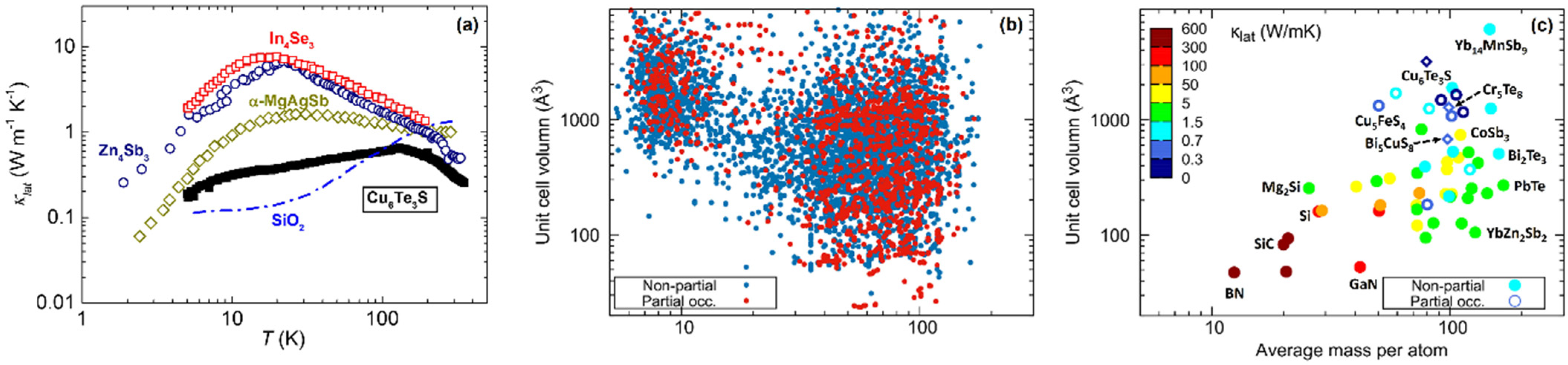
  62. Liu, Z.; Zhang, W.; Gao, W.; Mori, T. A material catalogue with glass-like thermal conductivity mediated by crystallographic occupancy for thermoelectric application. Energy Environ. Sci. 2021, 14, 3579–3587. [Google Scholar] [CrossRef]
  63. Pal, K.; He, J.; Wolverton, C. Bonding hierarchy gives rise to high thermoelectric performance in layered Zintl compound BaAu2P4. Chem. Mater. 2018, 30, 7760–7768. [Google Scholar] [CrossRef]
  64. Dutta, M.; Samanta, M.; Ghosh, T.; Voneshen, D.J.; Biswas, K. Evidence of highly anharmonic soft lattice vibrations in a Zintl rattler. Angew. Chem. Int. Ed. 2020, 60, 4259–4265. [Google Scholar] [CrossRef]
  65. Pandey, T.; Nissimagoudar, A.S.; Mishra, A.; Singh, A.K. Ultralow thermal conductivity and high thermoelectric figure of merit in mixed valence In5X5Br (X = S, and Se) compounds. J. Mater. Chem. A 2020, 8, 13812–13819. [Google Scholar] [CrossRef]
  66. Shen, Y.; Wang, F.Q.; Wang, Q. Ultralow thermal conductivity and negative thermal expansion of CuSCN. Nano Energy 2020, 73, 104822. [Google Scholar] [CrossRef]
  67. Sato, N.; Kuroda, N.; Nakamura, S.; Katsura, Y.; Kanazawa, I.; Kimura, K.; Mori, T. Bonding heterogeneity in mixed-anion compounds realizes ultralow lattice thermal conductivity. J. Mater. Chem. A 2021, 9, 22660–22669. [Google Scholar] [CrossRef]
  68. Barreteau, C.; Bérardan, D.; Amzallag, E.; Zhao, L.; Dragoe, N. Structural and electronic transport properties in Sr-doped BiCuSeO. Chem. Mater. 2012, 24, 3168–3178. [Google Scholar] [CrossRef]
  69. Pei, Y.-L.; He, J.; Li, J.-F.; Li, F.; Liu, Q.; Pan, W.; Barreteau, C.; Berardan, D.; Dragoe, N.; Zhao, L.-D. High thermoelectric performance of oxyselenides: Intrinsically low thermal conductivity of Ca-doped BiCuSeO. NPG Asia Mater. 2013, 5, e47. [Google Scholar] [CrossRef] [Green Version]
  70. Muchtar, A.R.; Srinivasan, B.; Tonquesse, S.L.; Singh, S.; Soelami, N.; Yuliarto, B.; Berthebaud, D.; Mori, T. Physical insights on the lattice softening driven mid-temperature range thermoelectrics of Ti/Zr-inserted SnTe—an outlook beyond the horizons of conventional phonon scattering and excavation of Heikes’ equation for estimating carrier properties. Adv. Energy Mater. 2021, 11, 2101122. [Google Scholar] [CrossRef]
  71. Liu, Y.; Zhou, M.; He, J. Towards higher thermoelectric performance of Bi2Te3 via defect engineering. Scr. Mater. 2016, 111, 39–43. [Google Scholar] [CrossRef]
  72. Uher, C. Thermoelectric properties of Skutterudites. In Thermoelectric Skutterudites; CRC Press: Boca Raton, FL, USA, 2021; pp. 261–318. [Google Scholar]
  73. Jovovic, V. Thermoelectric Waste Heat Recovery Program for Passenger Vehicles; Technique Report for Gentherm Incorporated; Gentherm Incorporated: Azusa, CA, USA, 2014. [Google Scholar]
  74. Salvador, J. Development of Cost-Competitive Advanced Thermoelectric Generators for Direct Conversion of Vehicle Waste Heat into Useful Electrical Power; Technique Report for General Motors LLC; General Motors LLC: Warrenton, VA, USA, 2017. [Google Scholar]
  75. Tan, G.; Zhao, L.-D.; Kanatzidis, M.G. Rationally designing high-performance bulk thermoelectric materials. Chem. Rev. 2016, 116, 12123–12149. [Google Scholar] [CrossRef]
  76. Tang, J.; Yao, Z.; Wu, Y.; Lin, S.; Xiong, F.; Li, W.; Chen, Y.; Zhu, T.; Pei, Y. Atomic disordering advances thermoelectric group IV telluride alloys with a multiband transport. Mater. Today Phys. 2020, 15, 100247. [Google Scholar] [CrossRef]
  77. Wang, L.; Tan, X.; Liu, G.; Xu, J.; Shao, H.; Yu, B.; Jiang, H.; Yue, S.; Jiang, J. Manipulating band convergence and resonant state in thermoelectric material SnTe by Mn–In codoping. ACS Energy Lett. 2017, 2, 1203–1207. [Google Scholar] [CrossRef]
  78. Hong, M.; Wang, Y.; Xu, S.; Shi, X.; Chen, L.; Zou, J.; Chen, Z.-G. Nanoscale pores plus precipitates rendering high-performance thermoelectric SnTe1-XSex with refined band structures. Nano Energy 2019, 60, 1–7. [Google Scholar] [CrossRef]
  79. Li, J.; Chen, Z.; Zhang, X.; Yu, H.; Wu, Z.; Xie, H.; Chen, Y.; Pei, Y. Simultaneous optimization of carrier concentration and alloy scattering for ultrahigh performance GeTe thermoelectrics. Adv. Sci. 2017, 4, 1700341. [Google Scholar] [CrossRef]
  80. Tsai, Y.-F.; Wei, P.-C.; Chang, L.; Wang, K.-K.; Yang, C.-C.; Lai, Y.-C.; Hsing, C.-R.; Wei, C.-M.; He, J.; Snyder, G.J.; et al. Compositional fluctuations locked by athermal transformation yielding high thermoelectric performance in GeTe. Adv. Mater. 2020, 33, 2005612. [Google Scholar] [CrossRef] [PubMed]
  81. Shuai, J.; Sun, Y.; Tan, X.; Mori, T. Manipulating the Ge vacancies and Ge precipitates through Cr doping for realizing the high-performance GeTe thermoelectric material. Small 2020, 16, 1906921. [Google Scholar] [CrossRef] [PubMed]
  82. Liu, Z.; Gao, W.; Zhang, W.; Sato, N.; Guo, Q.; Mori, T. High power factor and enhanced thermoelectric performance in Sc and Bi codoped GeTe: Insights into the hidden role of rhombohedral distortion degree. Adv. Energy Mater. 2020, 10, 2002588. [Google Scholar] [CrossRef]
  83. Liu, Z.; Sato, N.; Guo, Q.; Gao, W.; Mori, T. Shaping the role of germanium vacancies in germanium telluride: Metastable cubic structure stabilization, band structure modification, and stable n-type conduction. NPG Asia Mater. 2020, 12, 66. [Google Scholar] [CrossRef]
  84. Wang, L.; Li, J.; Zhang, C.; Ding, T.; Xie, Y.; Li, Y.; Liu, F.; Ao, W.; Zhang, C. Discovery of low-temperature GeTe-based thermoelectric alloys with high performance competing with Bi2Te3. J. Mater. Chem. A 2020, 8, 1660–1667. [Google Scholar] [CrossRef]
  85. Roychowdhury, S.; Ghosh, T.; Arora, R.; Samanta, M.; Xie, L.; Singh, N.K.; Soni, A.; He, J.; Waghmare, U.V.; Biswas, K. Enhanced atomic ordering leads to high thermoelectric performance in AgSbTe2. Science 2021, 371, 722–727. [Google Scholar] [CrossRef] [PubMed]
  86. Pei, J.; Cai, B.; Zhuang, H.-L.; Li, J.-F. Bi2Te3-Based applied thermoelectric materials: Research advances and new challenges. Natl. Sci. Rev. 2020, 7, 1856–1858. [Google Scholar] [CrossRef]
  87. Fang, T.; Li, X.; Hu, C.; Zhang, Q.; Yang, J.; Zhang, W.; Zhao, X.; Singh, D.J.; Zhu, T. Complex band structures and lattice dynamics of Bi2Te3-based compounds and solid solutions. Adv. Funct. Mater. 2019, 29, 1900677. [Google Scholar] [CrossRef]
  88. Liu, W.; Lukas, K.C.; McEnaney, K.; Lee, S.; Zhang, Q.; Opeil, C.P.; Chen, G.; Ren, Z. Studies on the Bi2Te3–Bi2Se3–Bi2S3 system for mid-temperature thermoelectric energy conversion. Energy Environ. Sci. 2013, 6, 552–560. [Google Scholar] [CrossRef]
  89. Pedersen, S.H. Thermoelectric properties of Zintl compounds Mg3Sb2-XBiX; Chemistry Project, Department of Chemistry, Aarhus University: Aarhus, DK, USA, 2012. [Google Scholar]
  90. Tamaki, H.; Sato, H.K.; Kanno, T. Isotropic conduction network and defect chemistry in Mg3+δSb2-based layered Zintl compounds with high thermoelectric performance. Adv. Mater. 2016, 28, 10182–10187. [Google Scholar] [CrossRef] [PubMed]
  91. Zhang, J.; Song, L.; Pedersen, S.H.; Yin, H.; Hung, L.T.; Iversen, B.B. Discovery of high-performance low-cost n-Type Mg3Sb2-Based Thermoelectric Materials with Multi-Valley Conduction Bands. Nat. Commun. 2017, 8, 13901. [Google Scholar] [CrossRef] [PubMed] [Green Version]
  92. Wood, M.; Kuo, J.J.; Imasato, K.; Snyder, G.J. Improvement of low-temperature zT in a Mg3Sb2–Mg3Bi2 Solid Solution via Mg-Vapor Annealing. Adv. Mater. 2019, 31, 1902337. [Google Scholar] [CrossRef]
  93. Song, S.W.; Mao, J.; Bordelon, M.; He, R.; Wang, Y.M.; Shuai, J.; Sun, J.Y.; Lei, X.B.; Ren, Z.S.; Chen, S.; et al. Joint effect of magnesium and yttrium on enhancing thermoelectric properties of N-type Zintl Mg3+δY0.02Sb1.5Bi0.5. Mater. Today Phys. 2019, 8, 25–33. [Google Scholar] [CrossRef]
  94. Li, A.; Fu, C.; Zhao, X.; Zhu, T. High-performance Mg3Sb2-xBix thermoelectrics: Progress and perspective. Research 2020, 2020, 1934848. [Google Scholar] [CrossRef]
  95. Liu, Z.; Sato, N.; Gao, W.; Yubuta, K.; Kawamoto, N.; Mitome, M.; Kurashima, K.; Owada, Y.; Nagase, K.; Lee, C.-H.; et al. Demonstration of ultrahigh thermoelectric efficiency of 7.3% in Mg3Sb2/MgAgSb module for low-temperature energy harvesting. Joule 2021, 5, 1196–1208. [Google Scholar] [CrossRef]
  96. Liu, Z.; Gao, W.; Oshima, H.; Nagase, K.; Lee, C.-H.; Mori, T. Maximizing the performance of N-type Mg3Bi2 based materials for room-temperature power generation and thermoelectric cooling. Nat. Commun. 2022, 13, 1120. [Google Scholar] [CrossRef]
  97. Zhao, H.; Sui, J.; Tang, Z.; Lan, Y.; Jie, Q.; Kraemer, D.; McEnaney, K.; Guloy, A.; Chen, G.; Ren, Z. High thermoelectric performance of MgAgSb-based materials. Nano Energy 2014, 7, 97–103. [Google Scholar] [CrossRef]
  98. Hendricks, T. Demonstrated high-performance, high-power skutterudite thermoelectric modules for space and terrestrial applications. In Proceedings of the 37th International Conference on Thermoelectrics 2018, Caen, France, 1–5 July 2018. [Google Scholar]
  99. Du, Y.; Xu, J.; Paul, B.; Eklund, P. Flexible thermoelectric materials and devices. Appl. Mater. Today 2018, 12, 366–388. [Google Scholar] [CrossRef]
  100. Wang, H.; Yu, C. Organic thermoelectrics: Materials preparation, performance optimization, and device integration. Joule 2019, 3, 53–80. [Google Scholar] [CrossRef] [Green Version]
  101. Lee, S.; Kim, S.; Pathak, A.; Tripathi, A.; Qiao, T.; Lee, Y.; Lee, H.; Woo, H.Y. Recent progress in organic thermoelectric materials and devices. Macromol. Res. 2020, 28, 531–552. [Google Scholar] [CrossRef]
  102. Xu, S.; Shi, X.-L.; Dargusch, M.; Di, C.; Zou, J.; Chen, Z.-G. Conducting polymer-based flexible thermoelectric materials and devices: From mechanisms to applications. Prog. Mater. Sci. 2021, 121, 100840. [Google Scholar] [CrossRef]
  103. Prunet, G.; Pawula, F.; Fleury, G.; Cloutet, E.; Robinson, A.J.; Hadziioannou, G.; Pakdel, A. A review on conductive polymers and their hybrids for flexible and wearable thermoelectric applications. Mater. Today Phys. 2021, 18, 100402. [Google Scholar] [CrossRef]
  104. Shi, X.; Chen, H.; Hao, F.; Liu, R.; Wang, T.; Qiu, P.; Burkhardt, U.; Grin, Y.; Chen, L. Room-temperature ductile inorganic semiconductor. Nat. Mater. 2018, 17, 421–426. [Google Scholar] [CrossRef]
  105. Satoh, N.; Otsuka, M.; Sakurai, Y.; Asami, T.; Goto, Y.; Kawamori, T.; Masaki, T.; Yatabe, G.; Kawakita, J.; Mori, T. Sticky Thermoelectric materials for flexible thermoelectric modules to capture low–temperature waste heat. MRS Adv. 2020, 5, 481–487. [Google Scholar] [CrossRef]
  106. Satoh, N.; Otsuka, M.; Kawakita, J.; Mori, T. A hierarchical design for thermoelectric hybrid materials: Partial Au skin Bi2Te3 particles enhance thermoelectric performances in sticky thermoelectric materials. Soft Sci. 2022, 2, 15. [Google Scholar] [CrossRef]
  107. Gonçalves, A.P.; Delaizir, G.; Lopes, E.B.; Ferreira, L.M.; Rouleau, O.; Godart, C. Chalcogenide Glasses as Prospective Thermoelectric Materials. J. Electron. Mater. 2011, 40, 1015–1017. [Google Scholar] [CrossRef]
  108. Vaney, J.B.; Piarristeguy, A.; Pradel, A.; Alleno, E.; Lenoir, B.; Candolfi, C.; Dauscher, A.; Gonçalves, A.P.; Lopes, E.B.; Delaizir, G.; et al. Thermal stability and thermoelectric properties of CuxAs40−xTe60−ySey semiconducting glasses. J. Solid State Chem. 2013, 203, 212–217. [Google Scholar] [CrossRef]
  109. Srinivasan, B.; Boussard-Pledel, C.; Dorcet, V.; Samanta, M.; Biswas, K.; Lefèvre, R.; Gascoin, F.; Cheviré, F.; Tricot, S.; Reece, M.; et al. Thermoelectric Properties of Highly-Crystallized Ge-Te-Se Glasses Doped with Cu/Bi. Materials 2017, 10, 328. [Google Scholar] [CrossRef] [PubMed]
  110. Suarez, F.; Nozariasbmarz, A.; Vashaee, D.; Öztürk, M.C. Designing thermoelectric generators for self-powered wearable electronics. Energy Environ. Sci. 2016, 9, 2099–2113. [Google Scholar] [CrossRef]
  111. Sugahara, T.; Ekubaru, Y.; Nong, N.V.; Kagami, N.; Ohata, K.; Hung, L.T.; Okajima, M.; Nambu, S.; Suganuma, K. Fabrication with semiconductor packaging technologies and characterization of a large-scale flexible thermoelectric module. Adv. Mater. Technol. 2018, 4, 1800556. [Google Scholar] [CrossRef]
  112. Nandihalli, N.; Gregory, D.; Mori, T. Energy-saving pathways for thermoelectric nanomaterial synthesis: Hydrothermal/solvothermal, microwave-assisted, solution-based, and powder processing polymer based thermoelectric nanocomposite materials and devices: Fabrication and characteristics. Adv. Sci. 2022, in press. [CrossRef]
  113. Glatz, W.; Schwyter, E.; Durrer, L.; Hierold, C. Bi2Te3-based flexible micro thermoelectric generator with optimized design. J. Microelectromech. Syst. 2009, 18, 763–772. [Google Scholar] [CrossRef]
  114. Yu, X.; Wang, Y.; Liu, Y.; Li, T.; Zhou, H.; Gao, X.; Feng, F.; Roinila, T.; Wang, Y. CMOS MEMS-based thermoelectric generator with an efficient heat dissipation path. J. Micromech. Microeng. 2012, 22, 105011. [Google Scholar] [CrossRef]
  115. Yanagisawa, R.; Tsujii, N.; Mori, T.; Ruther, P.; Paul, O.; Nomura, M. Nanostructured planar-type uni-leg Si thermoelectric generators. Appl. Phys. Express 2020, 13, 095001. [Google Scholar] [CrossRef]
  116. Mahfuz, M.M.H.; Tomita, M.; Hirao, S.; Katayama, K.; Oda, K.; Matsukawa, T.; Matsuki, T.; Watanabe, T. Designing a bileg silicon-nanowire thermoelectric generator with cavity-free structure. Jpn. J. Appl. Phys. 2021, 60, SBBF07. [Google Scholar] [CrossRef]
  117. Satoh, N.; Otsuka, M.; Ohki, T.; Ohi, A.; Sakurai, Y.; Yamashita, Y.; Mori, T. Organic π-type thermoelectric module supported by photolithographic mold: A working hypothesis of sticky thermoelectric materials. Sci. Technol. Adv. Mater. 2018, 19, 517–525. [Google Scholar] [CrossRef] [Green Version]
  118. Lima, M.S.L.; Aizawa, T.; Ohkubo, I.; Baba, T.; Sakurai, T.; Mori, T. High power factor in epitaxial Mg2Sn thin films via Ga doping, Appl. Phys. Lett 2021, 119, 254101. [Google Scholar]
  119. Ohkubo, I.; Murata, M.; Lima, M.S.L.; Sakurai, T.; Sugai, Y.; Ohi, A.; Aizawa, T.; Mori, T. Miniaturized in-plane π-type thermoelectric device composed of a II–IV semiconductor thin film prepared by microfabrication. Mater. Today Energy 2022, 28, 101075. [Google Scholar] [CrossRef]
  120. Bu, Z.; Zhang, X.; Shan, B.; Tang, J.; Liu, H.; Chen, Z.; Lin, S.; Li, W.; Pei, Y. Realizing a 14% Single-leg thermoelectric efficiency in GeTe alloys. Sci. Adv. 2021, 7. [Google Scholar] [CrossRef]
  121. Xing, T.; Song, Q.; Qiu, P.; Zhang, Q.; Gu, M.; Xia, X.; Liao, J.; Shi, X.; Chen, L. High efficiency GeTe-based materials and modules for thermoelectric power generation. Energy Environ. Sci. 2021, 14, 995–1003. [Google Scholar] [CrossRef]
  122. Mao, J.; Zhu, H.; Ding, Z.; Liu, Z.; Gamage, G.A.; Chen, G.; Ren, Z. High thermoelectric cooling performance of n-type Mg3Bi2-based materials. Science 2019, 365, 495–498. [Google Scholar] [CrossRef]
  123. Yang, J.; Li, G.; Zhu, H.; Chen, N.; Lu, T.; Gao, J.; Guo, L.; Xiang, J.; Sun, P.; Yao, Y.; et al. Next-generation thermoelectric cooling modules based on high-performance Mg3(Bi,Sb)2 material. Joule 2022, 6, 193–204. [Google Scholar] [CrossRef]
  124. Liang, Z.; Xu, C.; Shang, H.; Zhu, Q.; Ding, F.; Mao, J.; Ren, Z. High thermoelectric energy conversion efficiency of a unicouple of n-type Mg3Bi2 and p-Type Bi2Te3. Mater. Today Phys. 2021, 19, 100413. [Google Scholar] [CrossRef]
  125. Ying, P.; He, R.; Mao, J.; Zhang, Q.; Reith, H.; Sui, J.; Ren, Z.; Nielsch, K.; Schierning, G. Towards tellurium-free thermoelectric modules for power generation from low-grade heat. Nat. Commun. 2021, 12, 1121. [Google Scholar] [CrossRef]
  126. Wu, X.; Han, Z.; Zhu, Y.; Deng, B.; Zhu, K.; Liu, C.; Jiang, F.; Liu, W. A general design strategy for thermoelectric interface materials in n-type Mg3Sb1. 5Bi0.5 single leg used in TEGs. Acta Mater. 2022, 226, 117616. [Google Scholar]
  127. Wang, G.; Yang, J.; Zhao, H. Mg3(Bi, Sb)2-based thermoelectric modules towards near-room temperature cooling and power generation. J. Materiomics. in press. [CrossRef]
  128. Rajoo, S.; Romagnoli, A.; Martinez-Botas, R.; Pesiridis, A.; Copeland, C.; Bin Mamat, A.M.I. Automotive exhaust power and waste heat recovery technologies. In Automotive Exhaust Emissions and Energy Recovery; Nova Science Publishers: New York, USA, 2014; pp. 265–281. [Google Scholar]
  129. LaGrandeur, J.W. Thermoelectric waste heat recovery program for passenger vehicles. In 2012 Vehicle Technologies Program Annual Merit Review; Gentherm Incorporated: Azusa, CA, USA, 2012. [Google Scholar]
  130. Jumade, S.R.; Khond, V.W. A survey on waste heat recovery from internal combustion engine using thermoelectric technology. Int. J. Eng. Res. Technol. (IJERT) 2012, 1, 2278-0181. [Google Scholar]
  131. Fairbanks, J.W. The 60 percent efficient diesel engine; probable, possible, or just a fantasy. In Proceedings of the 2005 Diesel Engine Emissions Reduction (DEER) Conference, Chicago, IL, USA, 21–25 August 2005. [Google Scholar]
  132. Miller, E.W.; Hendricks, T.J.; Peterson, R.B. Modeling energy recovery using thermoelectric conversion integrated with an organic rankine bottoming cycle. J. Electron. Mater. 2009, 38, 1206–1213. [Google Scholar] [CrossRef]
  133. Hendricks, T.J.; Yee, S.; LeBlanc, S. Cost Scaling of a Real-World Exhaust Waste Heat Recovery Thermoelectric Generator: A Deeper Dive. J. Electron. Mater. 2015, 45, 1751–1761. [Google Scholar] [CrossRef]
  134. Hendricks, T.J. Thermoelectric System Economics—The Apex: New Paradigms in Manufacturing and Interface Performance Relationships Driving System Cost Optimizations. In Proceedings of the 2021 20th IEEE Intersociety Conference on Thermal and Thermomechanical Phenomena in Electronic Systems (iTherm), San Diego, CA, USA, 1–4 June 2021; IEEE: San Diego, CA, USA, 2021. [Google Scholar]
  135. LeBlanc, S.; Yee, S.K.; Scullin, M.L.; Dames, C.; Goodson, K.E. Material and Manufacturing Cost Considerations for Thermoelectrics. Renew. Sustain. Energy Rev. 2014, 32, 313–327. [Google Scholar] [CrossRef]
  136. Yee, S.K.; LeBlanc, S.; Goodson, K.E.; Dames, C. $ per W Metrics for Thermoelectric Power Generation: Beyond ZT. Energy Environ. Sci. 2013, 6, 2561–2571. [Google Scholar] [CrossRef]
  137. Geffroy, C.; Lilley, D.; Parez, P.S.; Prasher, R. Techno-Economic Analysis of Waste-Heat Conversion. Joule 2021, 5, 3080–3096. [Google Scholar] [CrossRef]
  138. Hendricks, T.J. Heat Exchanger Performance Impacts on Optimum Cost Conditions in Thermoelectric Energy Recovery Designs. Mater. Today Proc. 2018, 5, 10357–10370. [Google Scholar] [CrossRef]
  139. Min, G. Thermoelectric Module Design Theories. In Thermoelectrics Handbook, Rowe, D.M., Ed.; CRC Press: Boca Raton, FL, USA, 2005; Chapter 11; pp. 1–15. [Google Scholar]
  140. Fleurial, J.-P.; Bux, S.K.; Li, B.C.Y.; Firdosy, S.; Keyawa, N.R.; Gogna, P.K.; King, D.J.; Ma, J.M.; Star, K.; Zevalkink, A.; et al. Engineering of Novel Thermoelectric Materials and Devices for Next Generation, Long Life, 20% Efficient Space Power Systems. In Proceedings of the 2013 Materials Research Society Fall Meeting, Boston, MA, USA, 1–6 December 2013. [Google Scholar]
  141. Caillat, T.; Pinkowski, S.; Chi, I.; Huang, C.K.; Smith, K.; Yu, K.; Paik, J.; Gogna, P.; Phan, B.; Heian, E.; et al. An Update on the Development of Skutterudite-Based Thermoelectric Technology for Integration into a Potential Enhanced Multi-Mission Radioisotope Thermoelectric Generator (EMMRTG). In Proceedings of the Nuclear and Emerging Technologies for Space (NETS 2020), Las Vegas, NV, USA, 1 March 2020; The Electrochemical Society: Honolulu, HI, USA, 2020. [Google Scholar]
  142. Hendricks, T.J.; Mcenerney, B.; Drymiotis, F.; Furst, B.; Shevade, A. Design and Testing of High-Performance Mini-Channel Graphite Heat Exchangers in Thermoelectric Energy Recovery Systems. In Proceedings of the ASME International Mechanical Engineering Congress and Exposition, Tampa, Fl, USA, 3–9 November 2017; American Society of Mechanical Engineers Publishing: New York, NY, USA, 2017. [Google Scholar]
  143. Min, G.; Rowe, D.M. Optimisation of Thermoelectric Module Geometry for ‘waste Heat’ Electric Power Generation. J. Power Sources 1992, 38, 253–259. [Google Scholar] [CrossRef]
  144. Bjørk, R. The Universal Influence of Contact Resistance on the Efficiency of a Thermoelectric Generator. J. Electron. Mater. 2015, 44, 2869–2876. [Google Scholar] [CrossRef] [Green Version]
  145. Ouyang, Z.; Li, D. Modelling of Segmented High-Performance Thermoelectric Generators with Effects of Thermal Radiation, Electrical and Thermal Contact Resistances. Sci. Rep. 2016, 6, 24123. [Google Scholar] [CrossRef] [PubMed]
  146. Ziolkowski, P.; Poinas, P.; Leszczynski, J.; Karpinski, G.; Müller, E. Estimation of Thermoelectric Generator Performance by Finite Element Modeling. J. Electron. Mater. 2010, 39, 1934–1943. [Google Scholar] [CrossRef]
Figure 1. (a) Illustration of the paramagnon drag effect, (b) estimated power factor enhancement effect via Mn magnetic ion doping in CuGaTe2, (c) dependence of carrier effective mass versus Mn magnetic ion doping level [31].
Energies 15 07307 g001
Figure 2. Neutron measurements revealing (a) the existence of paramagnons and (b) paramagnon lifetime. Adapted from Science Advances 2019, 5, eaat9461 [32]. © The Authors, some rights reserved; exclusive licensee AAAS. Distributed under a CC BY-NC 4.0 license http://creativecommons.org/licenses/by-nc/4.0/ (accessed on 25 July 2022). Reprinted with permission from AAAS.
Energies 15 07307 g002
Figure 3. Seebeck coefficient of itinerant ferromagnetic Fe2.2V0.8Al0.6Si0.4. The green dashed line is the diffusion value extrapolated from low temperature [34].
Energies 15 07307 g003
Figure 4. (a) Glass-like thermal conductivity of Cu6Te3S with partial occupancy (b) obtained database of compounds with partial occupancy (c) low thermal conductivity compounds newly unearthed and verified utilizing partial occupancy as a descriptor [62].
Energies 15 07307 g004
Figure 5. Schematic of the change in the phonon DOS via mixed anion bond heterogeneity [67].
Energies 15 07307 g005
Figure 6. Contribution of the lattice softening effect versus phonon scattering effect to lower thermal conductivity in SnTe [70].
Energies 15 07307 g006
Figure 7. Examples of defect engineering in GeTe; (a) Cr doping to lower defect formation energy to create precipitations and defects to selectively lower thermal conductivity to enhance ZT [81], (b) high entropy AgInTe2 alloying to stabilize the defect-prone cubic phase (c) enabling heavy Bi doping for firt stable n-type in GeTe [83].
Energies 15 07307 g007
Figure 8. Minor Cu doping effect in Mg3Sb2 (a) schematic, (b) mobility, (c) thermal conductivity [95].
Energies 15 07307 g008
Figure 9. Illustration of the MMRTG and eMMRTG thermoelectric couples.
Energies 15 07307 g009
Figure 10. Photographs of (a) the eMMRTG SKD couple design currently on life testing and (b) the 1st SKD 48-couple module (bottom view showing the cold-side interconnects).
Energies 15 07307 g010
Figure 14. High-performance SKD-based TE module demonstrating 10% TE conversion efficiency and the highest reported power density in 2018.
Energies 15 07307 g014
Figure 15. (a) In-plane π-type thermoelectric device constructed by microfabrication, (b) schematic, (c) cross-section view at a π junction (p-type Mg2Sn0.8Sn0.2/metal electrode/n-type Bi), (d) microscopy image around the π junctions [115].
Energies 15 07307 g015
Figure 16. The measured conversion efficiency of eight pairs thermoelectric module of minor Cu-doped Mg3(Sb,Bi)2-type/MgAgSb-type as a function of hot-side temperature (cold side 278 K) [95].
Energies 15 07307 g016
Figure 17. Eight pairs thermoelectric module of minor Cu-doped Mg3(Sb,Bi)2-type/MgAgSb-type, with material modified toward low temperatures near room temperature (a) picture of module, (b) measured conversion efficiency and output power as a function of temperature difference ΔT (cold side 278 K), (c) measured maximum temperature difference ΔTmax and the maximum cooling power Qmax as a function of electric current I with Th = 323 K, (d) measured COP, compared with commercial Bi2Te3-type module [96].
Energies 15 07307 g017
Figure 18. (a) Thermal resistance network for exhaust heat recovery including leakage from the hot-side heat exchanger. (b) General heat and electrical energy flows. (c) Different representation of circuit (a) with resistances added to achieve variable 1/KH resistance representation.
Energies 15 07307 g018
Figure 19. System Hot-Side Heat Flux, Heat Exchanger Costs, and TE Material Costs Strongly Impact Overall TEG System Cost Minimization.
Energies 15 07307 g019
Figure 20. Electrical and Thermal Contact Interface Effects on Overall TEG Cost Minimization for Various Heat Exchanger Cost Parameters and Cost Sensitivities to TE Manufacturing Costs (r = 0.2).
Energies 15 07307 g020
Publisher’s Note: MDPI stays neutral with regard to jurisdictional claims in published maps and institutional affiliations.

