Article

Advanced Design of Integrated Heat Recovery and Supply System Using Heated Water Storage for Textile Dyeing Process

1
School of Chemical Engineering, Pusan National University, 2 Busandaehak-ro, 63beon-gil, Geumjeong-gu, Busan 46241, Korea
2
Advanced Textile R&D Department, Korea Institute of Industrial Technology (KITECH), 143 Hanggaulro, Sangnok-gu, Ansan-si 15588, Korea
*
Author to whom correspondence should be addressed.
Energies 2022, 15(19), 7298; https://doi.org/10.3390/en15197298
Submission received: 30 August 2022 / Revised: 28 September 2022 / Accepted: 29 September 2022 / Published: 4 October 2022

Abstract

:
Heat recovery from a high-temperature wastewater is the major concern in the conventional textile industry. However, limited space in the textile plant is an important constraint for the process enhancement. Therefore, an easily applicable heat recovery system with a small amount of additional equipment to the existing dyeing process is required. To meet the needs from the industry, this study suggests an integrated heat recovery and supply system consisting of single heat exchanger and single storage tank using freshwater as a thermal carrier to utilize the reusable heat in the wastewater. Freshwater is stored in a tank after direct heat exchange with wastewater and is supplied to the next dyeing process. Three different designs of the integrated system were compared based on the lower limit of the wastewater temperature: above 50 °C, 40 °C, and 30 °C for Cases 1, 2, and 3, respectively. The energy and energy flow analyses showed Case 2 to be well balanced between the quality and quantity of the recovered heat, and there was no heat loss via drainage. The heat demand for Case 2 was 795.5 kW, which was the lowest among all cases. Furthermore, an economic analysis showed that the total cost for Case 2 was reduced by 63.2% compared with the base case. Despite the use of an additional heat exchanger and water storage tank, the proposed system was more economical because of the reduced operating costs. Finally, a detailed analysis was conducted by determining the more efficient temperature for heat recovery and supply.

1. Introduction

The textile industry is energy intensive because it uses considerable fuel and power [1]. Reactive dyeing is commonly used in the textile industry to improve the quality of dyeing processes. In this method, a large quantity of preheated freshwater is required to induce the reaction between the fibers and the dye. Hence, a large amount of energy is required for heating to meet the process conditions [2]. For the dyeing process, the operating cost of heating the freshwater accounts for 16.2% of the total production cost [3]. In this conventional practice, a huge amount of energy is wasted to the environment during the dyeing process.
Waste heat recovery systems have been suggested as a solution to energy wastage in many industrial fields. Jouhara et al. [4] examined the waste heat recovery methodologies and state-of-the-art technologies for many industrial fields and presented the operating temperature range and the pros and cons of the heat recovery system. The research result indicated that energy efficiency could be improved by utilizing the proper heat recovery system for different industrial processes. Hammond and Norman [5] investigated the potential of various heat recovery systems using a database of the heat demand and surplus at United Kingdom industrial sites. The results indicated that recovery at low temperatures (below 100 °C) and conversion to electricity have great potential in the re-use of surplus heat. In the textile industry, recovering and using the wastewater heat during the dyeing process can reduce the energy demand and cost of heating [6]. In addition, the energy needed for cooling the wastewater is also saved because the wastewater temperature is decreased by the removal of heat [3]. Therefore, designing an efficient wastewater heat recovery (WWHR) process is crucial for achieving high performance in the dyeing process.
Many researchers have proposed heat recovery systems to effectively utilize waste heat in the dyeing process. Wu et al. [7] designed a capacity-regulated high-temperature heat pump (HTHP) system with a twin-screw compressor to recover waste heat in the dyeing process. Two tanks were used to store wastewater from the dyeing process, and the heat was recovered through the HTHP system. As a result, the operating cost decreased from USD 50,400 to USD 26,720, saving 47% of the total cost. Kannoh [8] used a waste heat recovery system consisting of a gas-fired absorption heat pump, heat exchanger, and three pumps to recover waste heat from warm water at different temperature ranges (20–50 °C). Consequently, the waste heat of 1.39 × 10⁹ J/h was recovered through the adsorption heat pump, and the hot water at 80 °C which had the heat of 3.48 × 10⁹ J/h was obtained. Kiran-Ciliz [9] proposed a cleaner production application for wet dyeing processes. Waste heat was utilized only through a water–water heat exchanger because sudden changes in the existing process are capital-intensive. According to theoretical calculations, a net energy of 0.3–0.4 kWh/kg of finished textile was saved. In addition, the economic feasibility analysis showed that the annual cost savings were USD 513,000. Rakib et al. [10] proposed a system that minimized the energy consumption by introducing a counter-flow shell and tube heat exchanger. The hot effluent was stored in an intermediate sump, and heat was transferred to cold freshwater. The results showed that the annual energy and cost savings were 5716 MWh and USD 47,100, respectively. Kandilli and Koclu [11] demonstrated the potential of reducing energy consumption during the dyeing process by utilizing a counter-flow plate heat exchanger. The optimal operating conditions for the heat exchanger were analyzed based on the first and second law of thermodynamics. The result revealed that the exergy improvement potential varied from 2.35 to 4.92 kW as the mass flow rate of waste and cold water changed. Dehghani and Yoo [12] designed a cascade trigeneration system to utilize low-grade waste heat and produce biofuel sources from textile wastewater. For the proposed system, energy and economic analysis were conducted. As a result, the proposed trigeneration system provided 88 kW equivalent electrical power with an efficiency of 62% and required five years payback period. Kim et al. [13] suggested a cost-optimal heat-exchange network. A heat pump was used to recover waste heat from the wastewater at temperatures below 30 °C; otherwise, the waste heat was recovered through the heat exchanger. A super-targeted pinch analysis was also conducted to minimize costs and maximize energy recovery. As a result, the total annualized cost (TAC) was reduced by 43.07% compared with that of the conventional dyeing process. In their further study [3], feasible scenarios of WWHR were defined, and the proposed WWHR system was optimized by conducting pinch and techno-economic analyses. Ultimately, the optimal WWHR system reduced the TAC by 28.6%.
Owing to the energy-intensive nature of the dyeing process, previous studies applied various heat-recovery systems using heat pumps and heat exchangers to effectively recover the waste heat discharged during the dyeing process. However, several limitations remain in the textile dyeing plant. First, due to the space limitations, it is hard to install many additional tanks and heat exchangers to the existing dyeing units. Second, if the heat exchange network becomes complicated, the operation becomes complex owing to the characteristics of a batch process. Third, as the number of heat exchangers increases, the additional capital investment increases. In the recent study, Zuberi et al. [14] suggested a heat recovery system with direct heat exchange and indirect heat exchange through a heat storage tank to improve energy efficiency. A practical case study on heat integration of a medium-sized European textile industry plant was presented using a pinch analysis method. Their result showed 25% and 7% of daily thermal energy saving using direct and indirect heat recovery, respectively. However, for the direct heat recovery, a maximum of seventeen heat exchangers were required and fifteen heat exchangers and a stratified tank are needed for the indirect heat recovery. Therefore, it requires a large space to install heat recovery equipment, and operates under complex modes.
To overcome the limitations of previous studies, and to provide applicable modifications to the existing textile dyeing plants, this study proposes the heat recovery and supply system consisting of a single heat exchanger and single tank using freshwater as the thermal carrier. Heat is transferred by a direct water-to-water heat exchange when wastewater is drained from the process. The heated freshwater is intermediately held in a water storage tank and directly used in the subsequent cycle. To find the best heat recovering condition of the proposed design, three different cases are generated by target heat recovering wastewater temperatures: (i) above 50 °C, (ii) above 40 °C, and (iii) wastewater from all processing steps, temperature above 30 °C. Energy and energy flow analyses are conducted to estimate the savings of steam usage and effectiveness of the proposed systems. Based on economic analysis, the economic feasibility of the system is evaluated. Furthermore, detailed energy and economic analyses are conducted at narrow temperature intervals to find more efficient operating conditions.

2. Methodology

2.1. Process Description

The major objective of this study is to effectively recover and use the waste heat generated during the dyeing process with applicable modification in the textile dyeing plant. The dyeing process in the textile industry consists of eight consecutive steps. First, bleaching, washing, and acidification are conducted during the pretreatment process. After the pretreatment process, dyeing is performed using a reactive dye. Finally, cold rinsing, washing, hot rinsing, and finishing are performed in the after-treatment process. Table 1 lists the operating time, wastewater temperature, and mass flow rate for each step of the dyeing process [13] and the flow chart of the dyeing process is presented in Figure 1. To achieve the objective of this study, a waste heat recovery system consisting of one heat exchanger and one storage tank was suggested, as shown in Figure 2. In the n-th dyeing process, the heat of high-temperature wastewater was recovered using freshwater as a heat sink. Next, in the n + 1-th dyeing process, heat was provided to each step through heated-water, which was the thermal carrier of waste heat. To compare the efficiency of the proposed system, wastewater discharge without heat recovery was selected as the base case. Case 1 recovered waste heat from wastewater that had a temperature of above 50 °C. In Case 2, wastewater above 40 °C was used to increase the amount of recovered heat. Case 3 recovered the waste heat from all steps (above 30 °C) to maximize the heat stored in the tank.
A simulation of the waste heat recovery system was performed using the commercial process simulation software Aspen HYSYS V11 (Aspentech). The Peng–Robinson equation of state was applied, which can predict the equilibrium phase properties of the full range of components [15], including water [16]. This process used freshwater as the working fluid to recover waste heat from the dyeing process. Freshwater flowed into the heat exchanger at a temperature and pressure of 18 °C and 101.3 kPa, respectively. A shell-and-tube heat exchanger was used. It was assumed that there was no heat loss in the heat exchanger, and the minimum temperature difference (MTD) was set to 5 °C. For the water storage tank, it was assumed that there was a 10% buffer in volume. The simulation design basis is presented in Table 2.

2.1.1. Case 1

In Case 1, the waste heat was recovered from wastewater above 50 °C. Since wastewater is generally sent to wastewater treatment systems below 40 °C [17], the wastewater from each step of the dyeing process was discharged at 40 °C after heat exchange in Case 1. From bleaching to finishing, as the process proceeded, the waste heat generated was recovered into freshwater through a heat exchanger. The wastewater from the six steps, except for cold rinsing and finishing, participated in the heat exchange. Freshwater flowed into the heat exchanger at 18 °C and absorbed heat to a temperature 5 °C lower than that of the wastewater. After heat exchange, heated-water, which is the freshwater that gained heat, was stored in a tank for the use in the next cycle. It was assumed that the temperature of the heated-water stored in the tank decreased by 5 °C owing to heat loss. The heated-water stored in the tank was preferentially supplied to the step with a higher temperature in the next cycle in the following order: bleaching, washing1, dyeing, washing2, and hot rinsing. To improve dyeing quality, heating during the dyeing step was carried out in two separate stages. In the first stage, freshwater was heated to 60 °C, and the temperature was steadily increased to 96 °C [7]. Owing to this feature, heated-water was supplied for dyeing at 60 °C and heated to 96 °C. After heated-water was provided at each step, additional freshwater was added when the heated-water was less than the required amount or the temperature was higher than the required temperature. The flow rate and temperature of the freshwater that recovered the heat are presented in Table 3, and the conditions of the heated-water are listed in Table 4.

2.1.2. Case 2

In Case 2, the waste heat was recovered from wastewater above the temperature of 40 °C to increase the amount of heat recovered. The wastewater was discharged at 30 °C after the heat exchange. Compared with Case 1, because a lower grade of waste heat can be recovered, finishing is included, and a total of seven steps were included in the heat exchange. As the amount of recoverable heat increased, the amount of heated-water stored in the tank also increased. Heated-water was supplied for bleaching, two washings, acidification, dyeing, hot rinsing, and finishing. The flow rate and temperature of the freshwater and heated-water are listed in Table 5 and Table 6, respectively.

2.1.3. Case 3

In Case 3, to maximize the quantity of recovered heat, wastewater from all eight steps was included in the heat exchange. Wastewater was cooled to 23 °C after the heat exchange, which was 5 °C higher than the inlet temperature of the freshwater. For this process condition, the tank held the largest amount of heated-water because the amount of recovered heat increased further. As in other cases, heated-water stored in the tank was first supplied to the dyeing process at a high temperature. Since a large amount of heated-water was stored in the tank, it could be supplied to all the steps of the dyeing process in the subsequent cycle. However, to meet the water temperature requirements in the steps, additional mixing with freshwater was required, and water remained in the tank even though heated-water was provided in all steps. It was assumed that the heated-water remaining in the tank was drained to avoid accumulation. The conditions for the freshwater and heated-water are listed in Table 7 and Table 8, respectively.

2.2. Energy Analysis Method

The total heat demand of the dyeing process was calculated as the sum of the energies consumed at each step, as follows:
T o t a l   h e a t   d e m a n d = Q B l e a c h i n g + Q W a s h i n g 1 + Q A c i d i f i c a t i o n + Q D y e i n g + Q C o l d   r i n s i n g + Q W a s h i n g 2 + Q H o t   r i n s i n g + Q F i n i s h i n g
where Q i is the energy required in each step, and the subscripts represent the dyeing process steps.

2.3. Cost Analysis Method

The cost analysis method was used to assess the cost reduction of the proposed heat recovery system and evaluate the efficiency of the three suggested cases in terms of cost. Table 9 presents the economic assumptions of the cost analysis.
The total cost of heat recovery system is calculated as:
Total   cost = C C A P E X + y = 1 P L C O P E X , y r 1 + r y
where C C A P E X is the capital cost, C O P E X , y r is the annual operating cost, r is the interest rate, and PL is the operating life of the plant.
Capital cost is calculated using the bare module factor and is expressed as follows:
C C A P E X = 1.18 × j = 1 P B j · C E , j · C E P C I 2022 C E P C I B a s e , j
where 1.18 is related to contingency and contractor fees, p indicates the equipment type, B j is the bare module factor, C E is the equipment purchase cost, and C E P C I is the chemical engineering plant cost index.
The purchase cost of heat exchanger is calculated as [18]:
log C E , H X = 3.2138 + 0.2688 log A 0 + 0.07961 ( log A 0 ) 2
where C E , H X is the purchase cost of the shell-and-tube heat exchanger, and A 0 is the heat transfer area.
The purchase cost of water storage tank is obtained as follows [19]:
C E , T a n k = 1.1 × 2150 × V 0.65
where C E , T a n k denotes the purchase cost of the tank, and V denotes the volume of the tank.
The operating cost is calculated as the sum of the steam cost used when raising the temperature of the dyeing process and the maintenance cost, expressed as
C O P E X , y r = C M a i n t + C s t e a m
where C M a i n t is maintenance cost, and C s t e a m is the steam cost.
The maintenance cost and steam cost are calculated as:
C M a i n t = 0.03 × C C A P E X
C s t e a m = t o p e r a t i n g × P r i c e s t e a m × Q ˙ S t e a m × C E P C I 2022 C E P C I B a s e
where t o p e r a t i n g is the operating hours, P r i c e s t e a m is the cost of steam, and Q ˙ S t e a m is the heat demand of the dyeing process. Annual maintenance cost was assumed to be 3% of the total CAPEX [20]. Table 10 presents the cost parameters used to calculate the total cost.
Table 9. Assumptions for the cost analysis.
ParameterValue
Interest rate [21]7%
Operating hours [7]8000 h/yr
Plant operating life [13]5 years
Steam cost [22]USD 1.16 × 10⁻⁵/kJ
Annual maintenance cost [20]3% of the total capital cost

3. Results and Discussion

3.1. Energy Analysis

An energy analysis was performed for the waste heat recovery and supply system to estimate the effectiveness of the proposed systems. The total heat demand for each case is shown in Figure 3. In the base case, a considerable amount of steam was used as the heat source to increase the temperature of the process. However, the proposed processes simultaneously utilize steam and recovered waste heat to satisfy the operating temperature requirements of the process. Therefore, the additional heat provided in the form of steam was reduced compared with that of the base case. The heat demands of the base case, Case 1, Case 2, and Case 3 were 2310.5, 1155.5, 795.5, and 843.2 kW, respectively. The case with the lowest energy consumption was Case 2, in which the energy consumption was reduced by 65.6% compared with the base case. Case 1, which recovered reusable heat from wastewater above 50 °C and discharged wastewater at 40 °C for wastewater treatment, had the highest heat demand among the three proposed processes. Furthermore, although Case 3 maximized the energy recovery, Case 2 had a lower energy consumption than Case 3. To analyze the three cases, it was important to examine the flow of the waste heat generated in each step. Thus, the energy flow analyses of the base case, Case 1, Case 2, and Case 3 were performed.
The energy flow for each case is shown in Figure 4. In the base case, all waste heat was released into the cooling water without the waste heat recovery process.
In Case 1, waste heat was recovered from six out of eight steps of the dyeing process and stored in a tank. The total load of heat stored in the tank was 1268.0 kW, and the heat discharged in wastewater was 1042.5 kW. Heated-water stored in the tank was supplied to the next cycle, and 112.9 kW of heat was lost during storage. The heat demand for the subsequent cycle was reduced compared to the base case. However, Case 1 had the highest value among the proposed cases owing to insufficient heat recovery. It means that there is a chance to recover more heat from the wastewater.
In Case 2, more heat was stored in the tank because the freshwater recovered reusable heat from wastewater above the temperature of 40 °C. Waste heat was recovered from seven out of eight steps of the dyeing process, and the load of stored heat was 1685.0 kW. As the recovered heat increased, the load of unrecovered heat in the process was reduced, and 625.5 kW was wasted in the wastewater. In addition, the energy input was further decreased, compared with Case 1, to 795.4 kW. Since the amount of heated-water stored in the tank was large, the heat loss of the tank increased; however, the total heat wasted decreased to 795.5 kW because the heat discharged to the wastewater was reduced in comparison with Case 1. The proper amount of heat was recovered, and the heat recovered was fully utilized in Case 2. Therefore, Case 2 had the lowest heat demand because the recovery and supply of the heat was well balanced.
In Case 3, the load of waste heat available was 2049.9 kW, which was the largest of the three cases owing to the additional heat recovery from the cold rinsing step. However, the heat demand in Case 3 was higher than that in Case 2; it is attributed to the following reasons: (1) The recovered heat had a low grade due to heat exchange with the lower temperature wastewater. (2) As the amount of heated-water stored in the tank increased, the heat loss of the tank increased. (3) Heated-water was discharged to prevent accumulation in the tank, i.e., some heat was lost because of drainage. Although the heat discharged to wastewater was decreased, the total wasted heat increased to 843.2 kW because the recovered heat could not be fully utilized in the subsequent cycle. Therefore, the energy input increased to supply the insufficient heat.
As a result of the energy analysis, it was found that Case 2 had the most suitable system configuration for heat recovery and supply. In Case 2, the temperature at which the wastewater was cooled through the heat exchanger was changed to determine more efficient conditions for heat recovery to save energy. Figure 5 shows the effect of temperature on heat demand and drainage. As the temperature decreased from 30 °C, the heat demand gradually decreased; however, below 25.1 °C, drainage occurred, and heat demand increased. Thus, 25.1 °C was the most efficient condition to reduce energy consumption, showing a heat demand of 618.6 kW, which is an 18.6% reduction compared with 759.5 kW at 30 °C. The energy flow under the most efficient conditions is shown in Figure 6. The load of heat recovered from each step and stored increased to 1,889.3 kW, and the waste heat discharged to wastewater decreased to 421.2 kW. In addition, because all the heat stored in the tank, except for the heat loss of the tank, was utilized to supply the heat required in the process, the energy input was further reduced to 618.6 kW. The energy analysis results showed that, by providing heated-water heated by wastewater, waste heat can be minimized, and more than half of the heating energy used in the dyeing process can be saved.

3.2. Economic Analysis

Economic analysis for each proposed process was performed using the equations in Section 2.3. The results of the OPEX, additional CAPEX, and total cost are shown in Figure 7. To calculate the total OPEX, it was assumed that the process operated for five years [13]. The total costs were USD 5.13 million, USD 2.66 million, USD 1.89 million, and USD 2.05 million for base case, Case 1, Case 2, and Case 3, respectively. By applying the heat recovery and supply system to the wastewater from the dyeing process, the total cost was reduced by 48.1% in Case 1, 63.2% in Case 2, and 60.0% in Case 3 compared with the base case.
Table 11 presents details of the economic analysis. The process proposed in this study involved recovering waste heat from wastewater using freshwater as the working fluid and storing the freshwater in a tank for use in the next cycle. Therefore, an additional heat exchanger and water tank were required for the proposed cases, and the corresponding CAPEX was incurred. The cost of the heat exchanger was calculated using the heat transfer area. In other words, as the flow rate of freshwater flowing into the heat exchanger increased, the equipment cost increased. The cost of the water tank was determined based on the volume of the tank; thus, the flow rate of the heated-water stored in the tank was important for calculating the equipment cost. Case 1 had the lowest flow rates of freshwater and heated-water; therefore, it had the lowest capital cost among the three cases. In contrast, Case 3, which had the highest flow rate of freshwater and heated-water, had the highest capital cost. CAPEX due to the additional equipment was USD 0.08 million for Case 1, USD 0.11 million for Case 2, and USD 0.16 million for Case 3.
OPEX comprises maintenance and steam costs, and most of it consist of the steam cost. Since the maintenance cost depends on CAPEX, Case 1 had the lowest value and Case 3 had the highest value. The cost of steam is proportional to the energy required for the dyeing process. Compared with the base case, the steam cost was reduced in all three cases because the heat demand was reduced by using a heat recovery and supply system. The OPEX values of the base case, Case 1, Case 2, and Case 3 were calculated as USD 5.13 million, USD 2.66 million, USD 1.89 million, and USD 2.05 million, respectively.
The proposed system required additional equipment for heat recovery; thus, a CAPEX was required. However, the steam cost was significantly reduced by recovering the waste heat. As a result, the proposed heat recovery and supply system is economically feasible owing to the reduction in the total cost by using the single heat exchanger and single heat storage tank. OPEX accounts for the largest portion of the total cost, and it is mainly affected by the heat demand of the process. As the heat demand in case 2 is the lowest, the total cost is also the lowest.
For Case 2, a more detailed economic analysis was conducted at varying wastewater cooling temperatures to determine the most cost-saving condition. Figure 8 shows the results of the economic analysis for Case 2 at varying temperatures. When the wastewater was cooled to a lower temperature, more freshwater flowed into the heat exchanger and the heat transfer area increased. In addition, the volume of the water tank was increased. Therefore, the CAPEX increases with decreasing temperature. OPEX showed an opposite tendency to that of CAPEX. At lower temperatures, OPEX was also low; because the degree of change in the value was larger in OPEX than in CAPEX, the total cost tended to be the same as that of OPEX. As a result, the total cost was USD 1.52 million at 25.1 °C, which was 19.6% lower than the USD 1.89 million at 30 °C.
Table 12 gives performance comparisons with recent studies on dyeing process heat recovery. Compared to the latest study [3], which shows the best heat recovery performance, the amount of the utility reduction of this study is relatively lower. However, the total cost of proposed design of this study is much lower than the previous one. It is caused by the number of additional equipment. By introducing an intermediate heated water storage tank, single heat exchanger can be applied to every processing step for the heat recovery. It results dramatic cost savings including additional equipment purchasing cost and operating cost for utility usage.

4. Conclusions

The heat recovery from the high-temperature wastewater is one of the most effective ways to reduce energy consumption in the textile dyeing plant. On the other hand, the space constraints in the real industry have to be considered in the heat recovery systems design. To address these two important issues, this study proposed an integrated heat recovery and supply system that uses a single heat exchanger and a single heat storage tank in the dyeing process. In the proposed system, freshwater, the thermal carrier is heated by direct heat exchange with wastewater and stored in a tank. Freshwater containing waste heat is then utilized as a thermal resource for the subsequent cycle of the dyeing process. The proposed system had three configurations based on the different wastewater temperatures used for heat recovery. In Case 1, reusable heat was recovered from wastewater above the temperature of 50 °C; waste heat was recovered from six of the eight steps of the dyeing process. In Case 2, freshwater recovered waste heat from wastewater above 40 °C; wastewater generated from seven steps, except for cold rinsing, was used to exchange heat. In Case 3, all steps participated in the heat exchange. The base case and proposed processes were compared through energy and economic analyses. For the most suitable configuration, further analysis was conducted by changing the temperature to find the most efficient energy- and cost-saving conditions. The results were as follows.
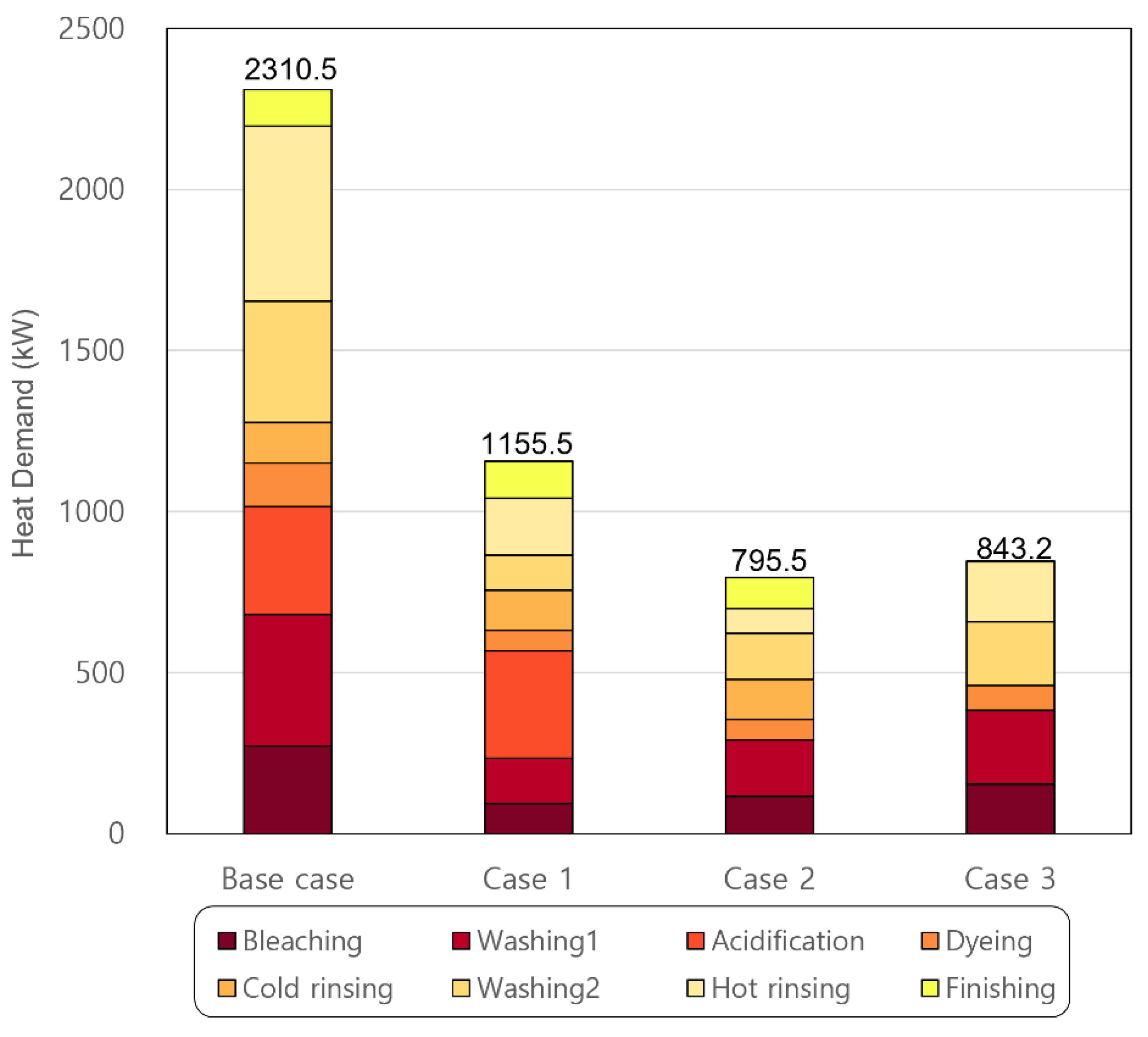
  • The integrated system showed a reduced heat demand compared with the base case because heat was recovered and utilized. There was a trade-off between the quantity and quality of the recovered heat. If waste heat in the lower temperature range was recovered, the heat quantity increased but the heat quality decreased. In addition, if the amount of heated-water was excessive, heat loss in the storage tank and freshwater drainage occurred. As a result of the energy analysis, it was found that Case 2 was well-balanced in these factors and had the lowest heat demand among the proposed processes.
  • The total cost of Case 2 was USD 1.89 million, which was the lowest among the three cases and was 63.2% lower than that of the base case. Although the systems used additional equipment that incurred more cost, the processes were advantageous in terms of cost because the reduction in steam cost was greater than the additional equipment cost.
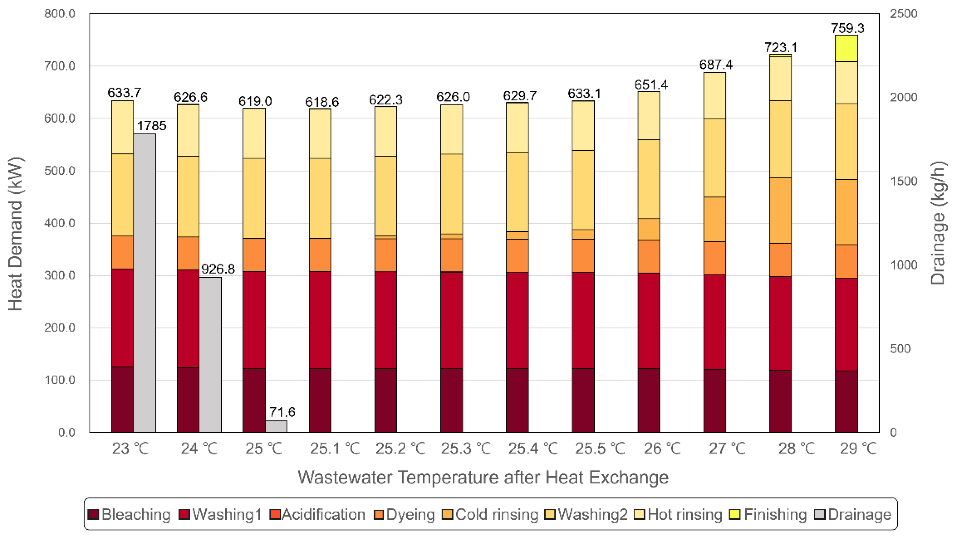
  • To determine the most energy- and cost-saving conditions, Case 2, which showed the best results in terms of energy and cost, was detail-analyzed for temperature. The results showed that, at 25.1 °C, the required energy decreased by 18.6% to 618.6 kW and cost decreased by 19.6% to USD 1.52 million.
In conclusion, the proposed system can effectively recover and supply heat during the dyeing process with the existing plant applicable modification, in addition to showing improvements in both energy and cost. Moreover, the potential to advance the integrated system was further investigated by searching for the most efficient operating conditions. This study is expected to contribute to the effective recovery and use of waste heat discharged from dyeing, which is an energy-intensive process.

Author Contributions

Conceptualization, J.S. and H.M.; data curation, H.M. and H.D.L.; methodology, J.S., H.M. and S.I.H.; software, J.S. and J.Y.S.; funding acquisition, I.L.; validation, J.S. and H.M.; visualization, J.S., H.D.L. and J.Y.S.; supervision, I.L.; formal analysis, J.S. and S.I.H.; investigation, H.M., S.I.H. and H.D.L.; resources, J.S. and J.Y.S.; project administration, I.L.; writing—original draft preparation, J.S. and H.M.; writing—review and editing, I.L. All authors have read and agreed to the published version of the manuscript.

Funding

This work was supported by the Korean Institute of Industrial Technology within the framework of the following projects: “Development of complex parameter smart analysis modules for color customering” (Grant No. EH-22-0011), the Korea Institute of Energy Technology Evaluation and Planning (KETEP) grant funded by the Korea government (MOTIE) (Grant No. 20214000000140), the Graduate School of Convergence for Clean Energy Integrated Power Generation.

Conflicts of Interest

The authors declare no conflict of interest.

Nomenclature

Abbreviations
CAPEXcapital expenditure (-)
CEPCIchemical engineering plant cost index (-)
HTHPhigh temperature heat pump
MTDminimum temperature difference (°C)
OPEXoperating expenditure
PLplant operating life (yr)
TACtotal annualized cost
WWHRwastewater heat recovery
Symbols
A 0 heat transfer area (m2)
B bare module factor (-)
C C A P E X capital cost (USD)
C E equipment purchase cost (USD)
C M a i n t maintenance cost (USD/yr)
C O P E X , y r annual operating cost (USD/yr)
C S t e a m steam cost (USD/yr)
P equipment type
P L plant operating life (yr)
P r i c e steam price (USD/kJ)
Q heat demand (kW)
r interest rate
t operating hours per year (hr/yr)
V volume (m3)
Subscripts
j ,   y counters
b a s e base year
H X shell-and tube-type heat exchanger
T a n k water storage tank
y r cost per year

References

  1. Palanichamy, C.; Babu, N.S. Second Stage Energy Conservation Experience with a Textile Industry. Energy Policy 2005, 33, 603–609. [Google Scholar] [CrossRef]
  2. Lim, J.; Lee, H.; Cho, H.; Shim, J.Y.; Lee, H.; Kim, J. Novel Waste Heat and Oil Recovery System in the Finishing Treatment of the Textile Process for Cleaner Production with Economic Improvement. Int. J. Energy Res. 2022. [Google Scholar] [CrossRef]
  3. Kim, Y.; Lim, J.; Shim, J.Y.; Lee, H.; Cho, H.; Kim, J. Optimizing Wastewater Heat Recovery Systems in Textile Dyeing Processes Using Pinch Analysis. Appl. Therm. Eng. 2022, 214, 118880. [Google Scholar] [CrossRef]
  4. Jouhara, H.; Khordehgah, N.; Almahmoud, S.; Delpech, B.; Chauhan, A.; Tassou, S.A. Waste Heat Recovery Technologies and Applications. Therm. Sci. Eng. Prog. 2018, 6, 268–289. [Google Scholar] [CrossRef]
  5. Hammond, G.P.; Norman, J.B. Heat Recovery Opportunities in UK Industry. Appl. Energy 2014, 116, 387–397. [Google Scholar] [CrossRef] [Green Version]
  6. Pulat, E.; Etemoglu, A.B.; Can, M. Waste-Heat Recovery Potential in Turkish Textile Industry: Case Study for City of Bursa. Renew. Sustain. Energy Rev. 2009, 13, 663–672. [Google Scholar] [CrossRef]
  7. Wu, X.; Xing, Z.; He, Z.; Wang, X.; Chen, W. Performance Evaluation of a Capacity-Regulated High Temperature Heat Pump for Waste Heat Recovery in Dyeing Industry. Appl. Therm. Eng. 2016, 93, 1193–1201. [Google Scholar] [CrossRef]
  8. Kannoh, S. Heat Recovery from Warm Waste Water at Dyeing Process by Absorption Heat Pump. J. Heat Recover. Syst. 1982, 2, 443–451. [Google Scholar] [CrossRef]
  9. Kiran-Ciliz, N. Reduction in Resource Consumption by Process Modifications in Cotton Wet Processes. J. Clean. Prod. 2003, 11, 481–486. [Google Scholar] [CrossRef]
  10. Rakib, M.I.; Saidur, R.; Mohamad, E.N.; Afifi, A.M. Waste-Heat Utilization—The Sustainable Technologies to Minimize Energy Consumption in Bangladesh Textile Sector. J. Clean. Prod. 2017, 142, 1867–1876. [Google Scholar] [CrossRef]
  11. Kandilli, C.; Koclu, A. Assessment of the Optimum Operation Conditions of a Plate Heat Exchanger for Waste Heat Recovery in Textile Industry. Renew. Sustain. Energy Rev. 2011, 15, 4424–4431. [Google Scholar] [CrossRef]
  12. Dehghani, M.J.; Kyoo Yoo, C. Modeling and Extensive Analysis of the Energy and Economics of Cooling, Heat, and Power Trigeneration (CCHP) from Textile Wastewater for Industrial Low-Grade Heat Recovery. Energy Convers. Manag. 2020, 205, 112451. [Google Scholar] [CrossRef]
  13. Kim, Y.; Lim, J.; Shim, J.Y.; Hong, S.; Lee, H.; Cho, H. Optimization of Heat Exchanger Network via Pinch Analysis in Heat Pump-Assisted Textile Industry Wastewater Heat Recovery System. Energies 2022, 15, 3090. [Google Scholar] [CrossRef]
  14. Zuberi, M.J.S.; Olsen, D.; Liem, P.; Wellig, B.; Patel, M.K. Heat Integration of a Multi-Product Batch Process by Means of Direct and Indirect Heat Recovery Using Thermal Energy Storage. Appl. Therm. Eng. 2020, 167, 114796. [Google Scholar] [CrossRef]
  15. Sun, T.; Takbiri-Borujeni, A.; Nourozieh, H.; Gu, M. Application of Peng-Robinson Equation of State for Modelling the Multiphase Equilibrium Properties in Athabasca Bitumen/Ethane Mixtures. Fuel 2019, 252, 439–447. [Google Scholar] [CrossRef]
  16. Escobedo, S.; Kong, J.; Lopez-Zamora, S.; de Lasa, H. Synthetic Naphtha Recovery from Water Streams: Vapour-Liquid–Liquid Equilibrium (VLLE) Studies in a Dynamic VL-Cell Unit with High Intensity Mixing. Can. J. Chem. Eng. 2022, 100, 607–625. [Google Scholar] [CrossRef]
  17. Li, C.; Zhang, Z.; Li, Y.; Cao, J. Study on Dyeing Wastewater Treatment at High Temperature by MBBR and the Thermotolerant Mechanism Based on Its Microbial Analysis. Process Biochem. 2015, 50, 1934–1941. [Google Scholar] [CrossRef]
  18. Fettaka, S.; Thibault, J.; Gupta, Y. Design of Shell-and-Tube Heat Exchangers Using Multiobjective Optimization. Int. J. Heat Mass Transf. 2013, 60, 343–354. [Google Scholar] [CrossRef]
  19. Lozano, M.A.; Mancini, C.; Serra, L.M.; Verda, V. Exergy and Thermoeconomic Analysis of a Solar Air Heating Plant. In Proceedings of the ASME 2014 12th Biennial Conference on Engineering Systems Design and Analysis, ESDA 2014, Copenhagen, Denmark, 25–27 June 2014; Volume 2, pp. 1–12. [Google Scholar]
  20. Park, S.; Noh, W.; Park, J.; Park, J.; Lee, I. Efficient Heat Exchange Configuration for Sub-Cooling Cycle of Hydrogen Liquefaction Process. Energies 2022, 15, 4560. [Google Scholar] [CrossRef]
  21. Park, J.; Lee, I.; You, F.; Moon, I. Economic Process Selection of Liquefied Natural Gas Regasification: Power Generation and Energy Storage Applications. Ind. Eng. Chem. Res. 2019, 58, 4946–4956. [Google Scholar] [CrossRef]
  22. Trisha, V.; Koh, K.S.; Ng, L.Y.; Chok, V.S. Heat Exchanger Network Retrofit of an Oleochemical Plant through a Cost and Energy Efficiency Approach. ChemEngineering 2021, 5, 17. [Google Scholar] [CrossRef]
  23. Noh, W.; Park, S.; Kim, J.; Lee, I. Comparative Design, Thermodynamic and Techno-Economic Analysis of Utilizing Liquefied Natural Gas Cold Energy for Hydrogen Liquefaction Processes. Int. J. Energy Res. 2022, 46, 12926–12947. [Google Scholar] [CrossRef]
  24. The Chemical Engineering Plant Cost Index. Available online: https://chemengonline.com/ (accessed on 15 August 2022).
Figure 1. Flow chart of the dyeing process.
Energies 15 07298 g001
Figure 2. Schematic of the waste heat recovery system in the dyeing process.
Energies 15 07298 g002
Figure 3. Heat demand of each case.
Energies 15 07298 g003
Figure 4. Energy flows in each case: (a) Base Case, (b) Case 1, (c) Case 2, and (d) Case 3.
Energies 15 07298 g004
Figure 5. Effect of temperature on heat demand and drainage in Case 2.
Energies 15 07298 g005
Figure 6. Energy flow for the most efficient wastewater temperature (25.1 °C) in Case 2.
Energies 15 07298 g006
Figure 7. Result of the economic analysis.
Energies 15 07298 g007
Figure 8. Economic analysis of Case 2 at varying temperatures.
Energies 15 07298 g008
Table 1. Process conditions of the dyeing process.
StageProcessProcess Time
(Min)
Temperature
(°C)
Mass Flow Rate
(kg/h)
1Bleaching30962900
2Washing20964350
3Acidification10508700
4Dyeing60961450
5Cold rinsing10308700
6Washing20904350
7Hot rinsing10708700
8Finishing20404350
Table 2. Process design basis.
ParameterValue
Fresh water temperature18 °C
Fresh water pressure101.3 kPa
Equipment pressure drop0 kPa
Temperature decreases in tank due to heat loss5 °C
Maximum temperature of discharged wastewater40 °C
Heat exchanger
 Equipment typeShell and tube
 Heat lossNone
 Minimum temperature difference5 °C
Table 3. Flow rate and temperature of heat-recovered freshwater (Case 1).
Fresh WaterMass Flow Rate (kg/h)Temperature (°C)
Bleaching to tank223191
Washing1 to tank334691
Acidification to tank322545
Dyeing to tank111591
Washing2 to tank325485
Hot rinsing to tank556265
Total18,73074.37
Table 4. Flow rate and temperature of heated-water (Case 1).
Heated-WaterMass Flow Rate (kg/h)Temperature (°C)
Tank to Bleaching290069.37
Tank to washing1435069.37
Tank to dyeing118069.37
Tank to washing2435069.37
Tank to hot rinsing595369.37
Table 5. Flow rate and temperature of heat-recovered freshwater (Case 2).
Fresh WaterMass Flow Rate (kg/h)Temperature (°C)
Bleaching to tank262691
Washing1 to tank393991
Acidification to tank644745
Dyeing to tank131391
Washing2 to tank390185
Hot rinsing to tank741165
Finishing to tank255935
Total28,20067.79
Table 6. Flow rate and temperature of heated-water (Case 2).
Heated-WaterMass Flow Rate (kg/h)Temperature (°C)
Tank to bleaching290062.79
Tank to washing1435062.79
Tank to acidification621062.79
Tank to dyeing135962.79
Tank to washing2435062.79
Tank to hot rinsing870062.79
Tank to Finishing328.562.79
Table 7. Flow rate and temperature of heat-recovered freshwater (Case 3).
Fresh WaterMass Flow Rate (kg/h)Temperature (°C)
Bleaching to tank290391
Washing1 to tank435591
Acidification to tank870245
Dyeing to tank145291
Cold rinsing to tank869925
Washing2 to tank435485
Hot rinsing to tank870565
Finishing to tank435035
Total43,52057.28
Table 8. Flow rate and temperature of the heated-water (Case 3).
Heated-WaterMass Flow Rate (kg/h)Temperature (°C)
Tank to bleaching290052.28
Tank to washing1435052.28
Tank to Acidification812052.28
Tank to dyeing145052.28
Tank to cold rinsing304452.28
Tank to washing2435052.28
Tank to hot rinsing870052.28
Tank to Finishing279052.28
Drainage781652.28
Table 10. Cost parameters for the economic analysis.
ParameterValue
Bare module factor
 Water tank [19]1.3
 Heat exchanger [23]3.17
Chemical engineering plant cost index (CEPCI) [24]
 2022 (Base year)806.3
 2021 (Steam)686.7
 2014 (Tank)576.1
 1996 (Shell-and-tube type exchanger)382.0
Table 11. Details of the economic analysis.
Cost
(USD Million)
Additional Capital CostOperating CostTotal Cost
Heat ExchangerWater TankAdditional Maintenance CostSteam Cost
Base case---5.1285.128
Case 10.0470.0360.0102.5642.659
Case 20.0660.0470.0141.7661.893
Case 30.0750.0630.0191.8712.048
Table 12. Performance comparison among various heat recovery systems on the dyeing process.
Kim et al., 2022 [13]Kim et al., 2022 [3]This Work
Heat recovery methodologyHEN * synthesis with pinchHEN * synthesis with pinchSingle heat exchanger, single tank
Design consideration Wastewater merging
into 2 streams
Wastewater merging
into 3 streams
Fresh water heating
and storage
Fresh water usage in one cycle 11,600 kg11,600 kg11,600 kg
Additional equipment requirement
 heat exchanger461
 heat pump cycle11-
 heat storage tank--1
Utility reduction51.5%73.7%65.6%
Total cost reduction43.1%28.6%63.2%
* HEN: Heat Exchange Network.
Publisher’s Note: MDPI stays neutral with regard to jurisdictional claims in published maps and institutional affiliations.

