Article

Hierarchical Distributed Coordinated Control for Battery Energy Storage Systems Participating in Frequency Regulation

1
School of Automation & Electrical Engineering, Lanzhou Jiaotong University, Lanzhou 730070, China
2
Electric Power Scientific Research Institute of State Grid Gansu Electric Power Company, Lanzhou 730070, China
3
School of New Energy and Power Engineering, Lanzhou Jiaotong University, Lanzhou 730070, China
*
Author to whom correspondence should be addressed.
Energies 2022, 15(19), 7283; https://doi.org/10.3390/en15197283
Submission received: 28 August 2022 / Revised: 24 September 2022 / Accepted: 28 September 2022 / Published: 4 October 2022

Abstract

:
At present, battery energy storage systems (BESS) have become an important resource for improving the frequency control performance of power grids under the situation of high penetration rates of new energy. Aiming at the problem that the existing control strategy is not sufficient for allocating the frequency regulation power instructions, a hierarchical distributed coordinated control strategy for BESS to participate in the automatic generation control (AGC) of a regional power grid is proposed. At the upper layer, the state of charge (SOC) of BESS and the technical characteristics of different frequency regulation power sources are comprehensively considered to complete the coordinated distribution of frequency regulation commands between BESS and traditional generators; at the lower layer, for the purpose of optimizing the economic operation of the regional power grid, the distributed consistency algorithm is used to control the distributed BESS in order to realize the fine management of power output of BESS. The simulation results indicate that this control strategy can give full play to the technical characteristics of different frequency power sources and improve the frequency regulation of the power grid. The excessive power consumption of BESS is successfully avoided, and the continuous operation of BESS is realized.

1. Introduction

To fulfill the goal of carbon neutral, the Chinese power utilities are advancing the development of a new power system dominated by new energy [1]. With the large-scale integration of new energy into power grids, its fluctuation and uncertainty have increased the burden of primary and secondary frequency regulation of grids, and the tertiary frequency regulation on the slow time scale will be seriously affected [2]. At present, the conventional generators have difficulty meeting the demand of frequency regulation in the form of the high permeability of new energy due to the characteristics of long frequency regulation time delay and low climbing rate. BESS has become an important frequency regulation resource for solving the problems of the conventional generators with its characteristics of rapid power output, high climbing rate and strong switching flexibility. The coordinated participation of both can not only make up for the shortcomings of the existing frequency regulation means but also improve the frequency regulation effect through BESS and reduce the reserve of system power margin [3]. Meanwhile, the introduction of BESS to participate in grid frequency regulation can also use time-of-use electricity price to increase the frequency regulation income of the power grid [4].
At present, the stability and economy of BESS in coordination with conventional generators to respond to AGC commands has become one of the research focuses of BESS participating in power grid frequency regulation [5,6]. Xie et al. proposed a control method for using BESS to coordinate response to frequency regulation signals with thermal power unit, which provided reference for subsequent large-capacity BESS projects [7]. The authors of [8,9,10,11] proposed using discrete Fourier transform and empirical mode decomposition to distribute instructions for two frequency regulation resources. Tang et al. proposed a frequency adjustment method model with the difference between the load side power change value and the generator side power change value as the feedback signal in order to stabilize the grid frequency [12]. Two frequency regulation methods based on area control error (ACE) signal and area regulation requirement (ARR) signal were proposed, and the influence of different participation of BESS on the frequency regulation effect was analyzed [13]. A fuzzy control strategy was used to perform secondary frequency regulation, and these results showed that this strategy could reduce the deviation in system frequency to a certain extent [14,15,16,17]. Oshnoei et al. proposed a robust LFC control method based on sparse communication network to use double-layer MPC to solve the problem of uncertain system model parameters [18]. For electrochemical energy storage system, its state of charge is one of the important points [19]. At present, energy storage is involved in grid frequency regulation, and the internal power of the energy storage system working on the power generation side changes greatly; for this reason, most control processes involve the control of the SOC of the BESS to avoid the overcharge and over-discharge of the BESS [20,21,22]. In [23], the authors constructed the control law of the two situations of adaptive frequency regulation and SOC recovery to achieve the coordination and cooperation of the two kinds of frequency regulation resources. Aiming at the consistency of the SOC of each BESS, a two-layer coordinated control strategy was proposed [20]. In order to eliminate the phenomenon of secondary drop of the frequency due to the exceeding of BESS capacity limit, a control strategy for switching the BESS between the frequency regulation mode and the recharge mode was proposed [24]. In order to eliminate the phenomenon of the secondary drop of the frequency due to the exceeding of BESS capacity limit, a control strategy for switching the BESS between the frequency regulation mode and the recharge mode was proposed [25]. The authors of [26] proposed a strategy that considered multiple factors such as frequency modulation effect, SOC and system economy, and optimized allocation through a grid adaptive search algorithm. The authors of [22] made deep analysis of the involvement of a BESS in secondary frequency modulation and proposed a control strategy model considering multiple constraints. In [26], the authors proposed the strategy of utilizing the idle capacity of an inverter to participate in the system’s frequency/peak regulation and set four types of SOC zones to ensure the coordinated operation of peak regulation and frequency modulation modes of BESS. From the perspective of reducing the number of energy storage uses and improving the response speed of thermal power units, [27] proposed a method of compensating for the climbing rate of the unit using the fast charging and discharging characteristics of BESS when the climbing rate of the unit cannot keep up with the AGC command.
The above studies prove the feasibility of BESS for participating in frequency regulation. Its main goal is to improve the system frequency regulation effect and its economic benefits, which also involves many factors to consider: (1) It is necessary to comprehensively consider the system frequency regulation requirements, the technical advantages of the two types of frequency resources, and the SOC management of BESS; (2) due to the high requirements of the power generation side for the power and capacity of BESS, it is usually necessary for multiple distributed BESS to jointly participate in the frequency regulation of the power grid. It is necessary to consider the frequency regulation characteristics of each distributed BESS in actual operation, rationally use the frequency regulation capacity of each distributed BESS, and solve the problem of poor scalability of centralized control. Therefore, a hierarchical distributed coordinated control strategy considering BESS to participate in AGC is proposed.
The structure of this paper is as follows: In Section 2, the working mechanism for BESS participating in secondary frequency regulation is analyzed, and the dynamic model of AGC of regional interconnected power system with distributed BESS is established. In Section 3, a two-layer coordinated control structure for distributed BESS to take part in frequency regulation in the power grid is proposed. In Section 4, the effectiveness of the proposed control strategy is verified in MATLAB/Simulink. In the end, the thesis is summarized in Section 5.

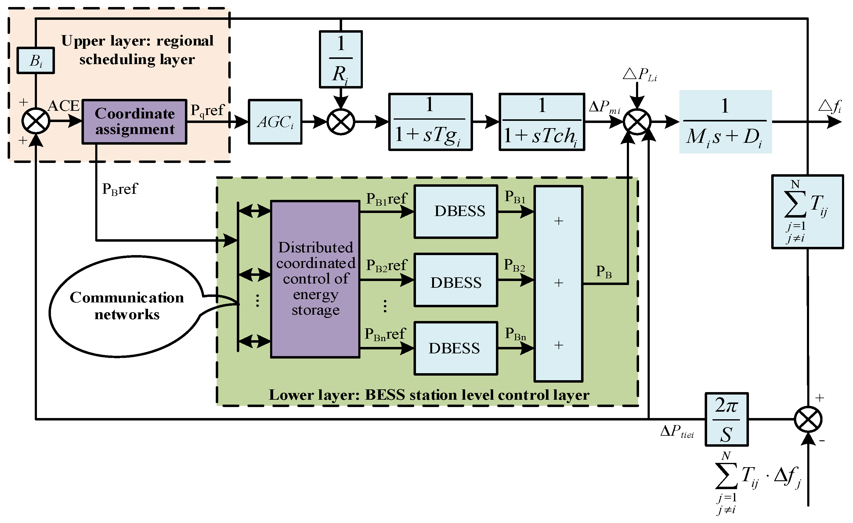
2. Dynamic Model of AGC for Regional Interconnection System with BESS

The frequency dynamic response model of the regional power grid with BESS described in this paper is shown in Figure 1, and each area is set up with a thermal power unit and an energy storage power station composed of n distributed BESS to jointly form frequency regulation resources. Δfi represents the system frequency deviation, Tgi and Tchi respectively represent the time constants of the governor and steam turbine, Mi represents the inertia constant of the generator, Di represents the load damping coefficient, Ri represents the governor difference coefficient, Bi represents the deviation factor, ΔPtiei represents the contact line power, ΔPmi represents the output power of the generator, ΔPli represents the load disturbance, Tij represents the synchronous torque coefficient between areas, ACEi represents the area control error, and TBi,b represents the response time constant of BESS.
The controller input signal of area i is the ACE signal; it can be described as follows:
A C E i = Δ P t i e i + B i Δ f i
where the deviation factor Bi can be described as follows:
B i = 1 R i + D i

3. Hierarchical Distributed Coordinated Control for BESS Participating in Frequency Regulation

Long-term continuous charging/discharging will make the SOC of a BESS too high/too low to ensure that the BESS can continue to participate in AGC, and in the case of long-term unidirectional frequency regulation, it may cause secondary disturbances to the frequency due to the overrun of capacity of a single energy storage source. Therefore, at the upper layer, this paper reasonably distributes the frequency regulation demand signals based on the frequency regulation requirements of the power grid, the respective frequency regulation characteristics of the two frequency control sources, and the recovery requirements of the SOC of the BESS. Furthermore, on the basis of meeting the needs of the power grid, the reduction of operation loss of BESS frequency regulation is beneficial for improving the overall economic benefits of BESS [28]. In view of this, the distributed consistency algorithm is used to achieve the response of the distributed BESS to the frequency regulation demand signal with the goal of the lowest cost of BESS at the lower layer. The control structure is shown in Figure 2.

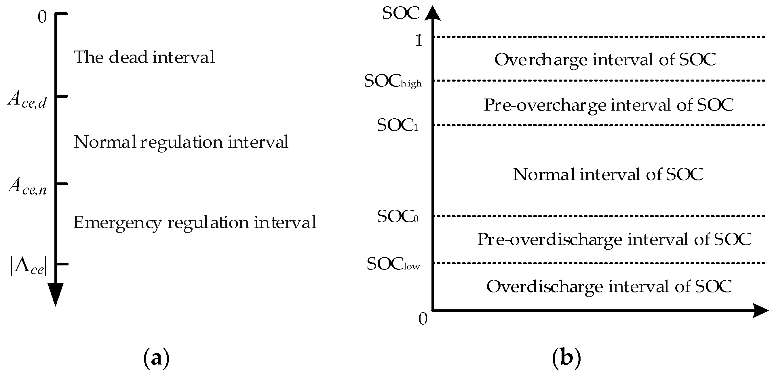
3.1. Frequency Regulation Control Policy for the Regional Dispatching Layer

At the regional dispatching layer, the frequency regulation requirements of the power grid are clarified first, and then the frequency regulation technology characteristics of BESS and traditional generator are comprehensively considered. In the end, the adjustment interval is divided according to the ACE signal, and the output target of each interval is determined in order to complete the initial power distribution of the BESS as a whole and the traditional generator. The control structure is shown in Figure 3.

3.1.1. The Dead Interval

When the ACE signal is in the dead interval, the power system is less disturbed. In order to ensure the continuity of BESS frequency regulation, the proposed strategy considers restoring the SOC to the ideal range as much as possible in this interval. In addition, it is necessary to ensure that the ACE signal does not jump out of the adjustment dead interval during SOC recovery. The ACE signal and the SOC of BESS are divided into state intervals, as shown in Figure 4. Ace,d and Ace,n are set to 0.003 and 0.08, respectively, and SOClow, SOC0, SOC1, and SOChigh are set to 0.1, 0.4, 0.6, and 0.9, respectively.
The required power for the SOC recovery of a BESS and the output power limits that do not exceed the ACE limit are determined separately. When the SOC is located in the ideal interval, the BESS does not work; on the contrary, it is necessary to restore the SOC of the BESS while ensuring that the grid frequency is normal. The output control strategy of the BESS is shown in Figure 5.
According to Figure 5, the specific expression of output power constraint for SOC recovery is as follows:
P d = { 0 S O C < S O C l o w P m S O C S O C 1 S O C h i g h S O C 1 S O C 1 S O C S O C h i g h P m S O C > S O C h i g h
P c = { 0 S O C > S O C 0 P m S O C S O C 0 S O C l o w S O C 0 S O C l o w S O C S O C 0 P m S O C < S O C l o w
Equations (3) and (4) represent the required power when the BESS is self-recovering, and Pm represents the rated output power of the BESS, multiplied by the constraint factor based on SOC feedback.
P c = { 0 A c e < 0.6 A c e , d P m ( 1 + A c e 0.6 A c e , d ) 0.6 A c e , d A c e 0 P m A c e > 0
P d = { 0 A c e > 0.6 A c e , d P m ( 1 A c e 0.6 A c e , d ) 0 A c e 0.6 A c e , d P m A c e < 0
Equations (5) and (6) are output power limits of the BESS that prevent the ACE from exceeding the limit when the SOC is restored.
In summary, the proposed strategy considers the required power for SOC recovery and the charge-discharge power that does not exceed the ACE limit, the final reference value of the BESS output PB,ref is shown in Equation (7).
P B , r e f = { min ( | P c | , | P c | ) S O C < S O C l o w min ( | P d | , | P d | ) S O C > S O C h i g h

3.1.2. The Normal Regulation Interval

When the ACE signal is located in this interval, the technical characteristics of the two frequency regulation resources can be combined to coordinate the distribution of the frequency regulation power. The specific control ideas are: When the SOC is located in the ideal interval, the characteristics of high climbing rate and accurate output can be used to give BESS priority to the frequency regulation signal; when the SOC exceeds the ideal interval, and the frequency regulation demand is beneficial to the SOC recovery of the BESS, the BESS takes part in frequency regulation with the maximum charge output power. Otherwise, the BESS does not take part in the frequency regulation. In addition, the maximum output power of the BESS needs to be limited accordingly based on SOC. The expression is as follows:
P B , max c = { P m S O C S O C 1   P m 100 P m e 1 15 ( S O C h i g h S O C ) S O C h i g h S O C 1 + 1 S O C 1   <   S O C <   S O C h i g h 0 S O C S O C h i g h
  P B , max c = { P m S O C S O C 1 P m 100 P m e 1 15 ( S O C h i g h S O C ) S O C h i g h S O C 1 + 1 S O C 1   <     S O C <   S O C h i g h 0 S O C S O C h i g h
The power distribution strategy of a BESS in the normal regulation interval can be obtained:
P B , r e f = { min ( | P m | , | Δ P A G C | ) S O C 0   S O C S O C 1 max ( P B , max c , Δ P A G C ) S O C S O C 0 & Δ P A G C 0 min ( P B , max d , Δ P A G C ) S O C S O C 1 & Δ P A G C 0 0 e l s e
where P B , max c and P B , max d are the maximum output power of BESS, their value greater than 0 indicates discharge, less than 0 indicates charge, and ΔPAGC indicates the power required for the frequency regulation of the power grid.

3.1.3. Emergency Regulation Interval

When the ACE signal is located in the emergency regulation interval, the power grid is greatly disturbed, and the primary goal at this time is to quickly reduce the ACE and restore it to the normal regulation interval. Therefore, the BESS still needs to take advantage of its fast response speed to provide rapid support. In addition, the SOC recovery of the BESS is no longer considered in the emergency regulation interval. The output control strategy of the BESS is as follows:
P B , r e f = { max ( Δ P A G C , P B , max c )   ( P B , r e f 0 ) min ( Δ P A G C , P B , max d )   ( P B , r e f > 0 )

3.2. Frequency Regulation Control Strategy at the BESS Station Level

After the initial reference power of the overall BESS is obtained by the upper layer, the distributed BESS coordinated control strategy is proposed based on the distributed consistency algorithm at the lower BESS station level, which aims to minimize the operating cost of BESS frequency regulation and completes the response of the distributed BESS to the frequency regulation demand under multi-constraint conditions based on the BESS frequency regulation cost model. The specific strategy is shown in Figure 6.

3.2.1. Frequency Regulation Operating Cost Function for BESS

The minimization of the frequency regulation operating costs of the BESS guarantees economically optimal power distribution in each control cycle [29]. In this process, it is necessary to consider its technical characteristics, including the frequency regulation backup capacity, climb rate, SOC, charge and discharge efficiency, and construct multi-constraint conditions.
First, it is necessary to consider the operating loss of the converter of the BESS element during power conversion and transmission. Its operating loss can be expressed by a quadratic equation with power as an independent variable [30,31], as follows:
C B i , k 1 = k 0 , i P B i , k 2 + k 1 , i P B i , k + k 2 , i
where k0,i, k1,i, and k2,i are the operating loss coefficients of the converter of the ith distributed BESS, and PBi,k is the output power of the ith distributed BESS at k time.
Second, due to the limited number of total charges and discharges of the BESS, the battery in the BESS cannot operate normally when the life is exhausted. Therefore, it is necessary to consider the aging cost of the battery, and the maximum number of charge and discharge times of BESS can be simulated into the power function form of its depth of discharge (DOD) [32]. The specific relationship is as follows:
n = λ 1 D O D λ 2
where n represents the maximum number of charge and discharge times of the battery and λ1 and λ2 are the corresponding coefficients. Assuming that the initial investment cost of the i-BESS is Cinv,i, the aging cost of the battery in the BESS can be expressed as:
C B i , k 2 = C i n v , i n = C i n v , i λ 1 D O D λ 2
When the BESS runs under constant voltage and constant current conditions, its output power is directly proportional to its DOD [33], which obtains the aging cost function of the battery of BESS that is only related to the output power amount of the BESS:
C B i , k 2 = C i n v , i λ 1 E B N , i λ 2 E B i , k λ 2
where EBi,k is the output power of the ith distributed BESS at k time and EBN,k is the rated capacity of the ith distributed BESS. In addition, the charging and discharging efficiency of the BESS during operation are considered for determining the output power of the BESS at k time and the SOC, which can be expressed as Equations (16) and (17), respectively:
E B i , k = { η i c P B i , k Δ t , P B i , k 0 P B i , k Δ t η i d , P B i , k > 0
S B i , k = { S B i , k 1 η i c P B i , k Δ t S B i , P B i , k 0 S B i , k 1 P B i , k Δ t S B i η i d , P B i , k > 0
The above-mentioned loss cost of the BESS converter is combined with the aging cost of the battery in which the BESS itself participates in frequency regulation; then, the total cost of the overall frequency regulation operation of BESS can be obtained:
C B i , k = C B i , k 1 + C B i , k 2

3.2.2. Operating Constraints of BESS Frequency Regulation

The frequency regulation capacity of a distributed BESS is constrained by its unequal constraints of frequency regulation power backup, ramp rate, and SOC, and it also needs to meet the equation constraints of power balance:
s . t . { P B i min P B i , k P B i max S O C B i min S O C B i , k S O C B i max R B i min P B i , k P B i , k 1 Δ t R B i max i = 1 n P B i , k = P B , r e f
where P B i min and P B i max represent the output power range of the BESS, S O C B i max and S O C B i max represent the SOC range of the BESS, and R B i min and R B i min represent the climbing rate range of the BESS.

3.2.3. Coordinated Control Strategy for BESS Based on Distributed Consistency Algorithm

From the previous two sections, the problem of the lowest operating cost of BESS frequency regulation can be expressed as a mathematical model with Equation (18) minimum as the target function and Equation (19) as the constraint. The key lies in the use of information interaction between adjacent distributed BESS to make the respective consistency variables finally converge to consistency.
To find the optimal power distribution solution for the minimum frequency regulation operating costs, the Lagrange equation is introduced [34]:
l ( P B i , k ) = i = 1 n C B i , k λ ( i = 1 n P B i , k P B , r e f )
The optimal solution satisfies the following conditions:
{ l i P B i , k = C B i , k P B i , k λ = 0 l i λ = i = 1 n P B i , k P B , r e f = 0
In this paper, the partial derivative of the frequency regulation operation cost function of the BESS to the frequency regulation output is taken as the consistency variable. Each distributed BESS exchanges information through the sparse communication network and designs an iterative update process of consistency variables according to the theory of distributed consistency algorithms, to finally achieve the convergence and consistency of the variables [35]. The flow chart of coordinated control in the control cycle is shown in Figure 7.
  • The reference power of a BESS determined by the upper layer initializes the consistency variable. Each distributed BESS undertakes the reference power in proportion to complete the initialization;
  • Each distributed BESS obtains the consistency variable of the adjacent distributed BESS through the communication topology set in advance and determines whether it is consistent with the consistency variable of the current distributed BESS λ agreement. Otherwise, the formula is used to iteratively update the consistency variables. A convergence accuracy ε is set considering that it is impossible for all consistency variables to be iteratively consistent in practice, and the approximate iteration can be completed within this range. The iterative process of consistency variables designed by the distributed consistency algorithm is:
    λ ¯ i , k + 1 m = j = 1 N B τ 1 h i j λ j , k + 1 m 1 + τ 2 ( P i , k + 1 0 P i , k )
    where λ ¯ i , k + 1 m is the consistency variable after m iteration at the k + 1 moment, hij is element of the sparse iteration matrix, P i , k + 1 0 is the initial allocated power at the k + 1 moment, Pi,k is the power allocation result at the previous moment, τ1 and τ2 are the weight coefficients in the distributed control algorithm.
  • The output power of the distributed BESS at that moment is obtained through the consistency variable obtained after the iterative update, and the SOC is updated. If the SOC exceeds the limit, the distributed BESS needs to be withdrawn from operation, and the system will update the communication network topology and re-initialize. Conversely, the power output is carried out in consideration of the the output power constraints of BESS. The model contains four distributed BESS participating in power grid frequency regulation, and its communication topology is shown in Figure 8; the communication relationship between different distributed BESS nodes is described by the connection diagram G = (V,E), where V = {1, 2, …, n} represents the collection of communication topology nodes, E ⊆ V × V represents the edge set of the communication path.

4. Simulation Results

4.1. Simulation Parameter Settings

A simulation model is established in MATLAB/Simulink as shown in Figure 1. The rated power of the non-reheat thermal power unit is 2000 MW, the frequency regulation reserve capacity is −100~100 MW, and the model is standardized with the unit rated power as the reference value. In addition, the optimal SOC and starting SOC of the distributed BESS are set to 0.5; the upper and lower limits of usable capacity are set to 0.9 times and 0.1 times of the rated capacity, respectively; and the initial investment cost of distributed BESS is 730 $/kW·h. The weight coefficients τ1 and τ2 of the distributed algorithm are set to 0.02 and 1.55, respectively, and the sampling interval by AGC is 4 s; the convergence accuracy is set to 0.01. The remaining specific parameters are shown in Table 1 and Table 2.

4.2. System Simulation Analysis

4.2.1. Step Load Disturbance Scenario

At 5 s, a load disturbance with a per-unit value of 0.02 is applied to the system, and the proposed strategies are compared with the conventional control strategies without BESS participation and fixed proportional allocation.
It can be seen from Figure 9 that under the step disturbance, the proposed strategy has the most obvious improvement in the maximum frequency deviation, and the frequency decline speed and system adjustment time are also smaller than the other two control strategies. As can be seen in Figure 10, among the three control strategies, the strategy without BESS participation has the highest conventional generator utilization, and the strategy in this paper has a higher utilization rate of the conventional generator than the control strategy based on fixed proportion allocation. This is because the proposed strategy makes full use of the remaining frequency regulation capacity of the conventional generator set to recover the SOC of distributed BESS, which improves the utilization rate of a conventional generator.
As shown in Figure 11, under the proposed strategy, with the increase in the number of iterations, the consistency variable of each distributed BESS finally reaches approximate consistency, which verifies the convergence of the distributed consistency algorithm. As shown in Figure 12 and Figure 13, under the control strategy of this paper, the SOC of each distributed energy storage is effectively maintained in the range of 0.42~0.5. Based on the strategy of fixed proportion allocation, the SOC of individual distributed BESS deteriorates seriously due to the continuous output of the BESS throughout the frequency regulation process. For example, distributed BESS4 even reaches the critical SOC of 0.1.

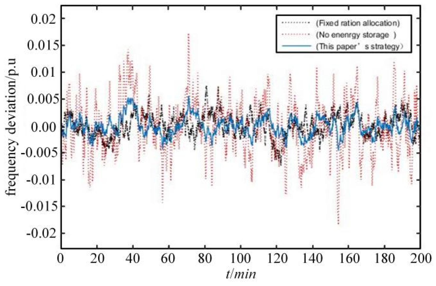
4.2.2. Continuous Load Disturbance Scenarios

A continuous disturbance signal with a small range is applied to the system as shown in Figure 14. The proposed strategy is compared with the conventional control strategy without BESS participation and fixed proportional allocation.
It can be seen in Figure 15 that compared with Figure 16, under the long-term continuous load step disturbance, the proposed strategy can quickly suppress the frequency deviation of the power system and control it to fluctuate in a small range. The recovery time of this article strategy is also shorter than that of the other two control strategies. Similarly, in the two control strategies that both contain energy storage, the proposed strategy has a higher utilization rate of conventional generator.
Figure 17 and Figure 18 show the SOC of each distributed BESS based on the strategy of fixed proportion allocation and the proposed strategy, respectively. It can be seen that under the long-term continuous load disturbance, the SOC of each distributed BESS based on the proposed strategy fluctuates in the range of 0.4 to 0.6. This is because under the proposed strategy, each distributed BESS can adjust its own frequency regulation responsibilities in time according to its real-time status to achieve economic distribution. Furthermore, the distributed BESS based on the strategy of fixed proportion allocation, due to the lack of adaptive control of SOC, there is an overuse of distributed BESS4, and the overall SOC maintenance effect is poor.

5. Conclusions

In order to make the best of the frequency regulation characteristics of each distributed energy storage in the large-scale BESS, while taking into account the frequency regulation requirements of the power grid and the SOC management of BESS, a hierarchical distributed coordinated control strategy using BESS to participate in the AGC control of the regional power grid is proposed. The advantages are as follows:
  • By adjusting the frequency regulation responsibility of each frequency regulation resource adaptively, the proposed strategy can not only ensure the frequency modulation effect of the system but also avoid excessive power loss of the BESS, so as to maximize the operating margin of BESS and realize the continuous economic operation of BESS.
  • The proposed distributed control strategy takes into account the energy level and power limit of each distributed BESS, adjusts the frequency modulation output of each distributed BESS based on the operation economy, and maintains the respective SOC near the ideal value, so as to achieve the balance between the system frequency regulation performance and the operation economy, which has better robustness and control flexibility than the centralized control method.
  • Each distributed BESS can adjust the frequency regulation output according to its respective operating economy to achieve economic optimization, so as to achieve the balance between the system frequency regulation performance and operating economy, which has better economy and control flexibility than the traditional control method.
  • Since the proposed strategy makes full use of the residual capacity of the conventional generator to restore the SOC of BESS, the utilization rate of the secondary frequency regulation of the conventional generator is improved.

Author Contributions

Conceptualization, Z.Z. and Q.L.; methodology, B.Y.; software, B.Y.; validation, B.Y. and H.D.; formal analysis, H.D.; investigation, B.Y.; resources, Q.L.; data curation, B.Y.; writing—original draft preparation, B.Y.; writing—review and editing, B.Y. and H.D.; project administration, H.D. All authors have read and agreed to the published version of the manuscript.

Funding

This research was funded by the Science and Technology Project of State Grid Corporation of China, grant number W22KJ2722005.

Institutional Review Board Statement

Not applicable.

Informed Consent Statement

Not applicable.

Data Availability Statement

Not applicable.

Conflicts of Interest

The authors declare that they have no conflict of interest to report regarding the present study.

References

  1. Li, S.; Li, X.; Kang, Y.; Gao, Q. Load capability assessment and enhancement for transformers with integration of large-scale renewable energy: A brief review. Front. Energy Res. 2022. [Google Scholar] [CrossRef]
  2. Weng, X.S.; Yue, D.; Dou, X.C. Event-triggered mechanism based distributed optimal frequency regulation of power grid. IET Control. Theory Appl. 2019, 13, 2994–3005. [Google Scholar] [CrossRef]
  3. Li, J.L.; Ma, H.M.; Hui, D. Present Development Condition and Trends of Energy Storage Technology in the Integration of Distributed Renewable Energy. Trans. China Electrotech. Soc. 2016, 31, 1–10. [Google Scholar] [CrossRef]
  4. Yu, C.H.; Wu, J.P.; Yang, H.J.; Li, Z.H.; Teng, X.L. Frequency regulation strategy for power grid incorporating large-scale energy storage. Electr. Power Eng. Technol. 2019, 38, 68–73+105. [Google Scholar]
  5. Wang, K.F.; Xie, L.R.; Qiao, Y.; Lu, Z.X.; Yang, H. Analysis of frequency regulation performance of power system improved by battery energy storage. Autom. Electr. Power Syst. 2021, 46, 174–181. [Google Scholar]
  6. Lu, X.J.; Yin, J.W.; Li, Y. Optimal control strategy of AGC with participation of energy storage system based on multi-objective mesh adaptive direct search algorithm. Power Syst. Technol. 2019, 43, 2116–2124. [Google Scholar]
  7. Xie, X.; Guo, Y.; Wang, B.; Dong, Y.; Fei, X. Improving AGC performance of coal-fueled thermal generators using multi-mw scale BESS: A practical application. IEEE Trans. Smart Grid 2018, 9, 1769–1777. [Google Scholar] [CrossRef]
  8. Ren, L.Q.; Bai, Z.Y.; Yu, C.H.; Wang, Y.M.; Zheng, L. Research on active power control strategy for wind/photovoltaic/energy storage hybrid power system and its engineering application. Autom. Electr. Power Syst. 2014, 38, 105–111. [Google Scholar]
  9. Hu, Z.C.; Xie, X.; Zhang, F.; Zhang, J.; Song, Y.H. Research on automatic generation control strategy incorporating energy storage resources. Proc. CSEE 2014, 34, 5080–5087. [Google Scholar] [CrossRef]
  10. Jia, Y.B.; Zheng, J.; Chen, H.; Yan, Z.; Wang, J.H. Capacity allocation optimization of energy storage in thermal-storage frequency regulation dispatch system based on EEMD. Power Syst. Technol. 2018, 42, 2930–2937. [Google Scholar] [CrossRef]
  11. Tang, J.; Li, X.R.; Huang, J.Y.; Xu, P.; He, C. Capacity allocation of BESS in secondary frequency regulation with the goal of maximum net benefit. Trans. China Electrotech. Soc. 2019, 34, 963–972. [Google Scholar] [CrossRef]
  12. Tang, M.L.; Pei, Z.Y.; Shen, Y.J.; Wang, Q.S. Frequency regulation of thermal power units assisted by battery energy storage system. In Proceedings of the IEEE IAS Industrial and Commercial Power System Asia, Chengdu, China, 18–21 July 2021; pp. 69–73. [Google Scholar] [CrossRef]
  13. Zhu, H.; Wang, K.F.; Qiao, Y.; Xie, L.R.; Liu, G.J. Research on the substitution ability of battery energy storage system for thermal power units in frequency regulation. In Proceedings of the IEEE Sustainable Power and Energy Conference, Chengdu, China, 23–25 November 2020; pp. 712–718. [Google Scholar] [CrossRef]
  14. Ding, D.; Liu, Z.Q.; Yang, S.L.; Wu, X.G.; Li, T.T. Battery energy storage aid automatic generation control for load frequency control based on fuzzy control. Power Syst. Prot. Control. 2015, 43, 81–87. [Google Scholar]
  15. Li, P.Q.; Tan, Z.X.; Zhou, Y.J.; Li, C.B.; Li, R. Secondary frequency regulation strategy with fuzzy logic method and self-adaptive modification of state of charge. IEEE Access 2018, 6, 43575–43585. [Google Scholar] [CrossRef]
  16. Cui, H.F.; Yang, B.; Jiang, Y.; Tan, Z.X.; Cui, D. Strategy based on fuzzy control and self adaptive modification of SOC involved in secondary frequency regulation with battery energy storage. Power Syst. Prot. Control. 2019, 47, 89–97. [Google Scholar] [CrossRef]
  17. Wang, K.; Qiao, Y.; Xie, L. A fuzzy hierarchical strategy for improving frequency regulation of battery energy storage system. J. Mod. Power Syst. Clean Energy 2021, 9, 689–698. [Google Scholar] [CrossRef]
  18. Oshnoei, A.; Kheradmandi, M.; Muyeen, S.M. Robust control scheme for distributed battery energy storage systems in load frequency control. IEEE Trans. Power Syst. 2020, 35, 4781–4791. [Google Scholar] [CrossRef]
  19. Cui, Z.H.; Kang, L.; Li, L.W.; Wang, L.C.; Wang, K. A hybrid neural network model with improved input for state of charge estimation of lithium-ion battery at low temperatures. Renew. Energy 2022. [Google Scholar] [CrossRef]
  20. Ye, L.; Wang, K.F.; Lai, Y.L.; Chen, H.; Zhao, Y.L. A review of analysis of frequency characteristics and control strategies of battery energy Storage frequency regulation in power system under low inertia level. Power Syst. Technol. 2022. [Google Scholar] [CrossRef]
  21. Li, J.L.; Qu, S.K.; Ma, S.L.; Zeng, W.; Xiong, J.J. Research on frequency modulation control strategy of auxiliary power grid in battery energy storage system. J. Sol. Energy 2022, 1–12. [Google Scholar] [CrossRef]
  22. Liu, Y.P.; Tian, S.J.; Liang, H.P.; Xie, Y.; Huo, Q.D. Control strategy of a battery energy storage system considering SOC in primary frequency regulation of power grid. Power Syst. Prot. Control. 2022, 50, 107–118. [Google Scholar]
  23. Li, R.; Li, X.R.; Tan, Z.X.; Huang, J.Y.; Ma, Z.H. Frequency control considering deep and fast load changing capability of thermal power units. Autom. Electr. Power Syst. 2018, 42, 74–82. [Google Scholar]
  24. Lv, L.X.; Chen, S.H.; Zhang, X.B.; Pang, T.; Huang, C.X. Control strategy for secondary frequency regulation of power system considering SOC consensus of large-scale battery energy storage. Therm. Power Gener. 2021, 50, 108–117. [Google Scholar] [CrossRef]
  25. Zhao, T.; Parisio, A.; Milanovic, J. Distributed control of battery energy storage systems for improved frequency regulation. IEEE Trans. Power Syst. 2020, 35, 3729–3738. [Google Scholar] [CrossRef]
  26. Ding, M.; Shi, J.X.; Han, P.P. Integrated control strategy for photovoltaic storage system to participate in power grid frequency regulation and peak regulation. China Electr. Power 2021, 54, 116–123. [Google Scholar]
  27. Zhao, Y.X.; Gen, G.C.; Jiang, Q.Y. Frequency control strategy of single-generator supporting by energy storage considering power change rate. Electr. Power Autom. Equip. 2020, 40, 141–147. [Google Scholar]
  28. Zhang, S.Q.; Yuan, B.; Ji, Z.D.; Wei, X.J.; Zhao, J.F. A secondary frequency control based on the distributed control theory considering battery energy storage systems. Trans. China Electrotech. Soc. 2019, 34, 637–645. [Google Scholar] [CrossRef]
  29. He, L. Research on the Coordinated Control Strategy for Distributed Energy Storages in Hybrid AC/DC Power Grid. Ph.D. Thesis, Hunan University, Changsha, China, June 2020. [Google Scholar]
  30. Spangler, R.; Shoults, R. Power generation, operation, and control. IEEE Power Energy Mag. 2014, 12, 90–93. [Google Scholar]
  31. Zhang, Z.; Chow, M. Convergence analysis of the incremental cost consensus algorithm under different communication network topologies in a smart grid. IEEE Trans. Power Syst. 2012, 27, 1761–1768. [Google Scholar] [CrossRef]
  32. Duggal, I.; Venkatesh, B. Short-term scheduling of thermal generators and battery storage with depth of discharge-based cost model. IEEE Trans. Power Syst. 2015, 30, 2110–2118. [Google Scholar] [CrossRef]
  33. Chen, G.; Bao, Q.Y.; Zhang, J.L.; Wang, B.B.; Wu, M. Distributed cooperative control strategy for energy storage units considering life loss cost. Power Syst. Technol. 2018, 42, 1495–1501. [Google Scholar] [CrossRef]
  34. Chen, F.; Chen, M.; Li, Q.; Meng, K.; Guerrero, J. Cost-based droop schemes for economic dispatch in islanded microgrids. IEEE Trans. Smart Grid 2017, 8, 63–74. [Google Scholar] [CrossRef] [Green Version]
  35. Olfati-Saber, R.; Fax, J.A.; Murray, R.M. Consensus and cooperation in networked multi-agent systems. Proc. IEEE 2007, 95, 215–233. [Google Scholar] [CrossRef]
Figure 1. Frequency dynamic response model of regional power grid with BESS.
Energies 15 07283 g001
Figure 2. Two-layer coordinated control structure diagram.
Energies 15 07283 g002
Figure 3. Regional dispatch layer frequency regulation control structure.
Energies 15 07283 g003
Figure 4. (a) Schematic diagram of the state partitions of ACE; (b) Schematic diagram of the state partitions of SOC.
Energies 15 07283 g004
Figure 5. (a) Energy storage for SOC recovery power demand; (b) output power limit to prevent ACE from exceeding the limit.
Energies 15 07283 g005
Figure 6. Distributed coordinated control strategy at the BESS station level.
Energies 15 07283 g006
Figure 7. Coordination control flowchart during the control cycle.
Energies 15 07283 g007
Figure 8. The communication network topology of fourdistributed BESS.
Energies 15 07283 g008
Figure 9. Frequency deviation.
Energies 15 07283 g009
Figure 10. Output increment of conventional generator.
Energies 15 07283 g010
Figure 11. Consistency variable of BESS.
Energies 15 07283 g011
Figure 12. SOC of the BESS.
Energies 15 07283 g012
Figure 13. SOC of the BESS based on power ratio.
Energies 15 07283 g013
Figure 14. Long-term load disturbance.
Energies 15 07283 g014
Figure 15. Frequency deviation.
Energies 15 07283 g015
Figure 16. Output increment of conventional generator.
Energies 15 07283 g016
Figure 17. SOC of the DBESS.
Energies 15 07283 g017
Figure 18. SOC of the DBESS based on power ratio.
Energies 15 07283 g018
Table 1. Basic experimental parameters of the model.
ParameterNumeric Value
System frequency/Hzf = 50 Hz
Difference factor/(per-unit value)R = 2.4
Frequency deviation coefficient/(per-unit value)B = 0.045
Governor time constant/sTg = 0.03
Turbine time constant/sTch = 0.3
Generator inertia time constant/(per-unit value)M = 0.17
Generator load damping coefficient/(per-unit value)D = 0.008
Proportions, integration constantsKP = 0.755, Ki = 1.038
Table 2. Basic parameters of the distributed BESS.
NumberPower Range/MWClimbing Range/(MW/h)Rated Capacity/(MW·h)Charge/Discharge EfficiencyEnergy Storage Time ConstantConverter Operating Loss Coefficient
BESS1±10±103100.85/0.800.010.0213, 0.0103, 0.2078
BESS2±10±1038.50.90/0.850.010.2130, 0.0103, 0.4078
BESS3±9±8006.50.95/0.900.010.0224, 0.014, 0.1560
BESS4±5±8004.50.90/0.900.010.0217, 0.0108, 0.5076
Publisher’s Note: MDPI stays neutral with regard to jurisdictional claims in published maps and institutional affiliations.

