
Safety Evaluation and Energy Consumption Analysis of Deep Foundation Pit Excavation through Numerical Simulation and In-Site Monitoring


Abstract
:1. Introduction
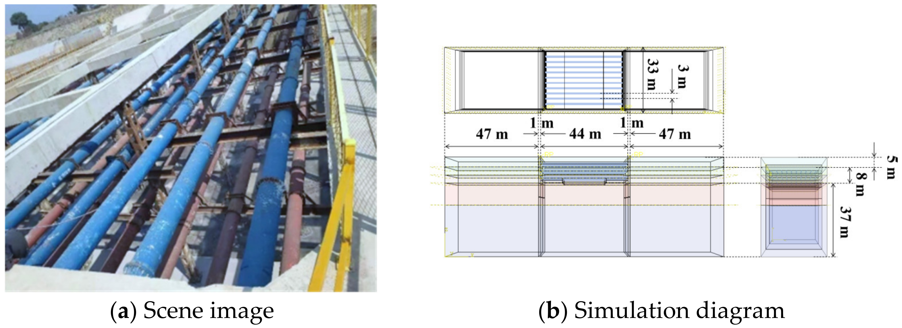
2. Project Overview
2.1. Structure Dimensions
2.2. Parameters of Soils and Materials
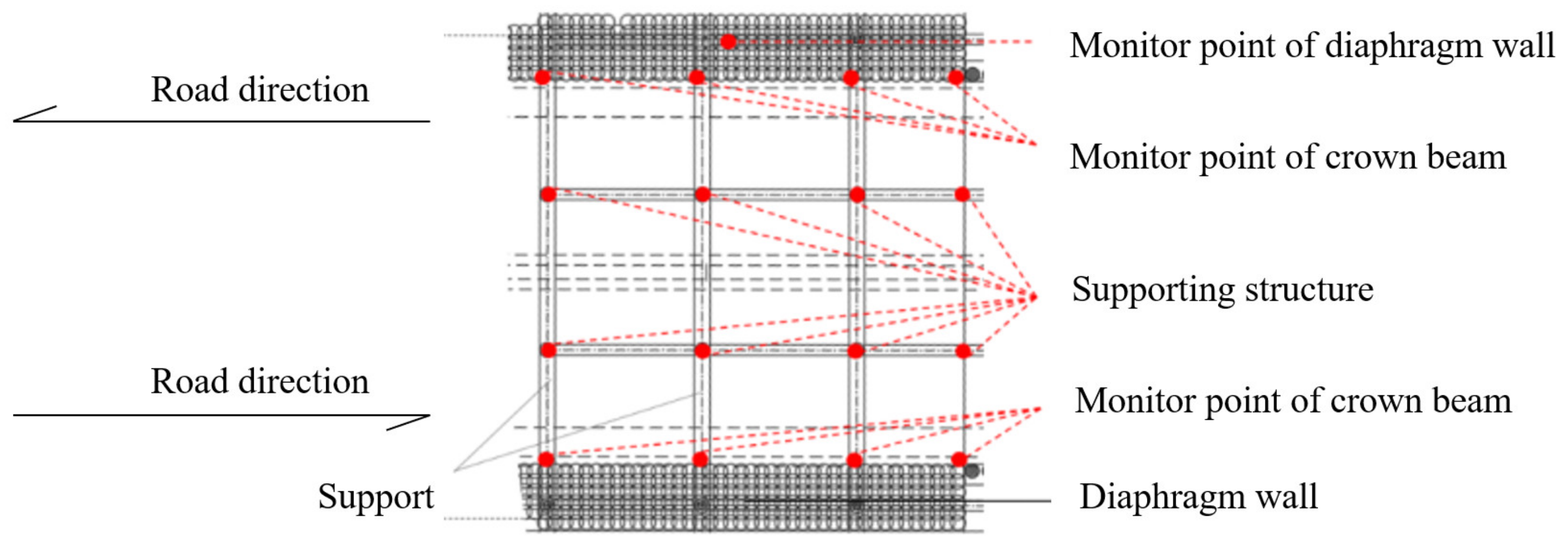
2.3. Monitoring Methods
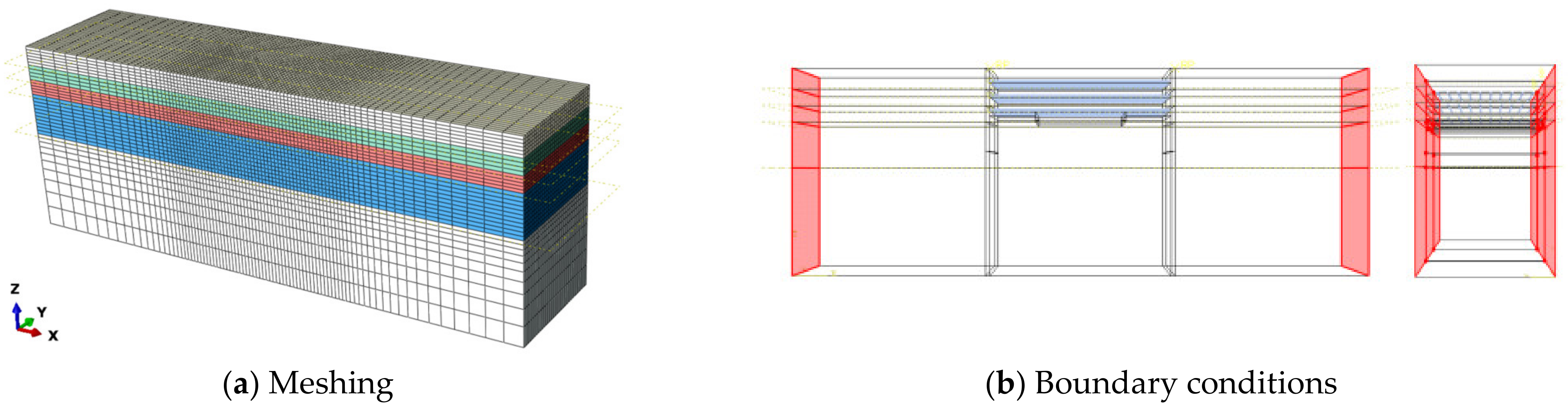
2.4. Mesh and Boundary Conditions
3. Monitored Data during Construction
3.1. Groundwater Level
3.2. Displacement of Diaphragm Wall
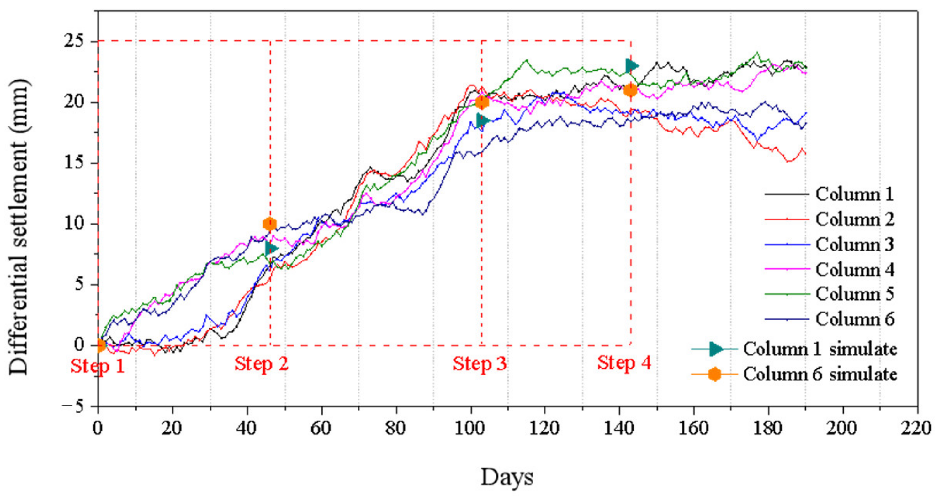
3.3. Differential Settlement of Column
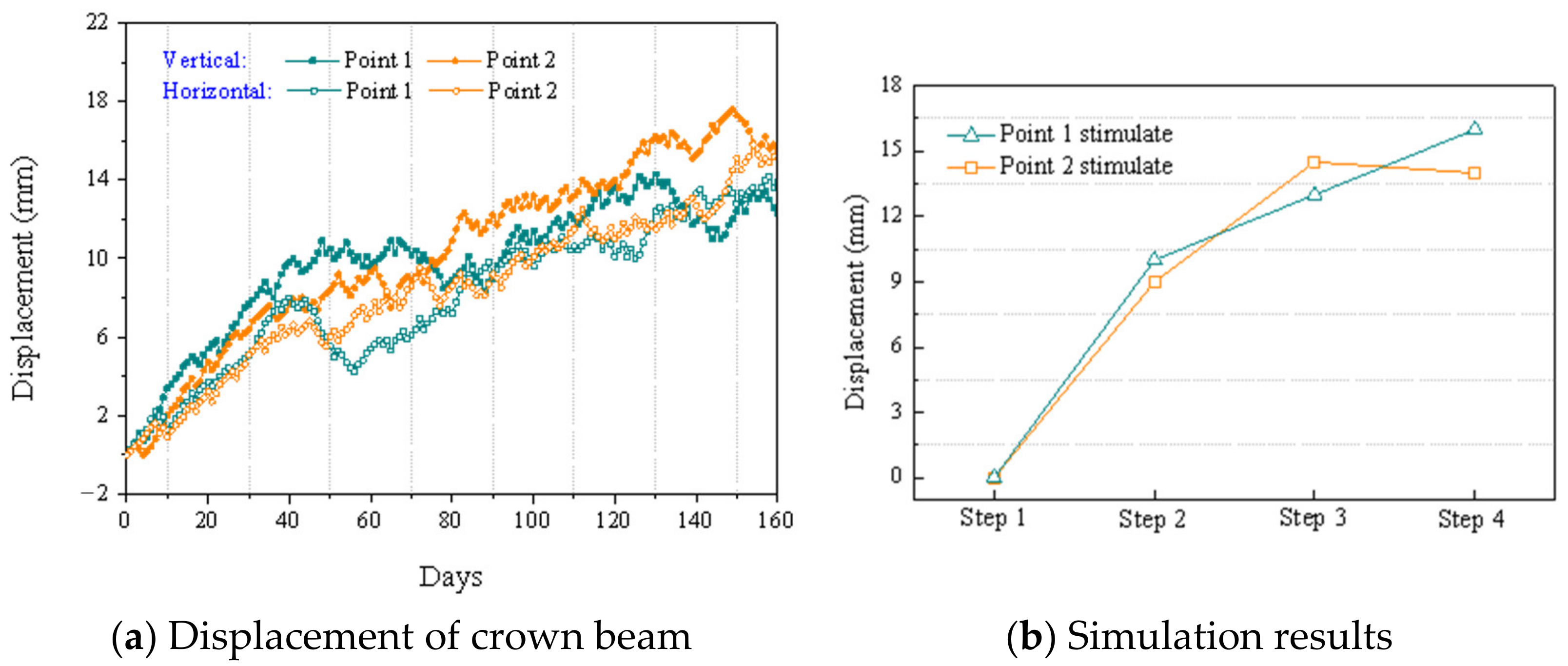
3.4. Displacement of Crown Beam
4. Results and Discussion
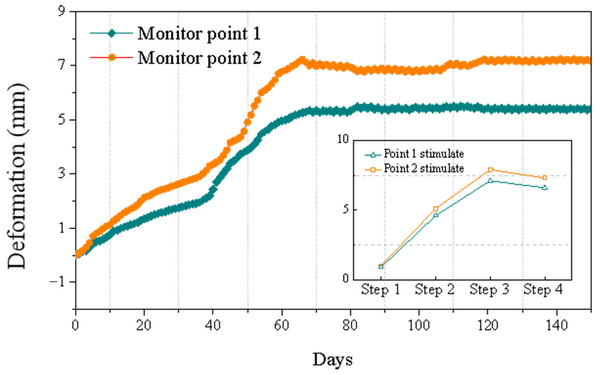
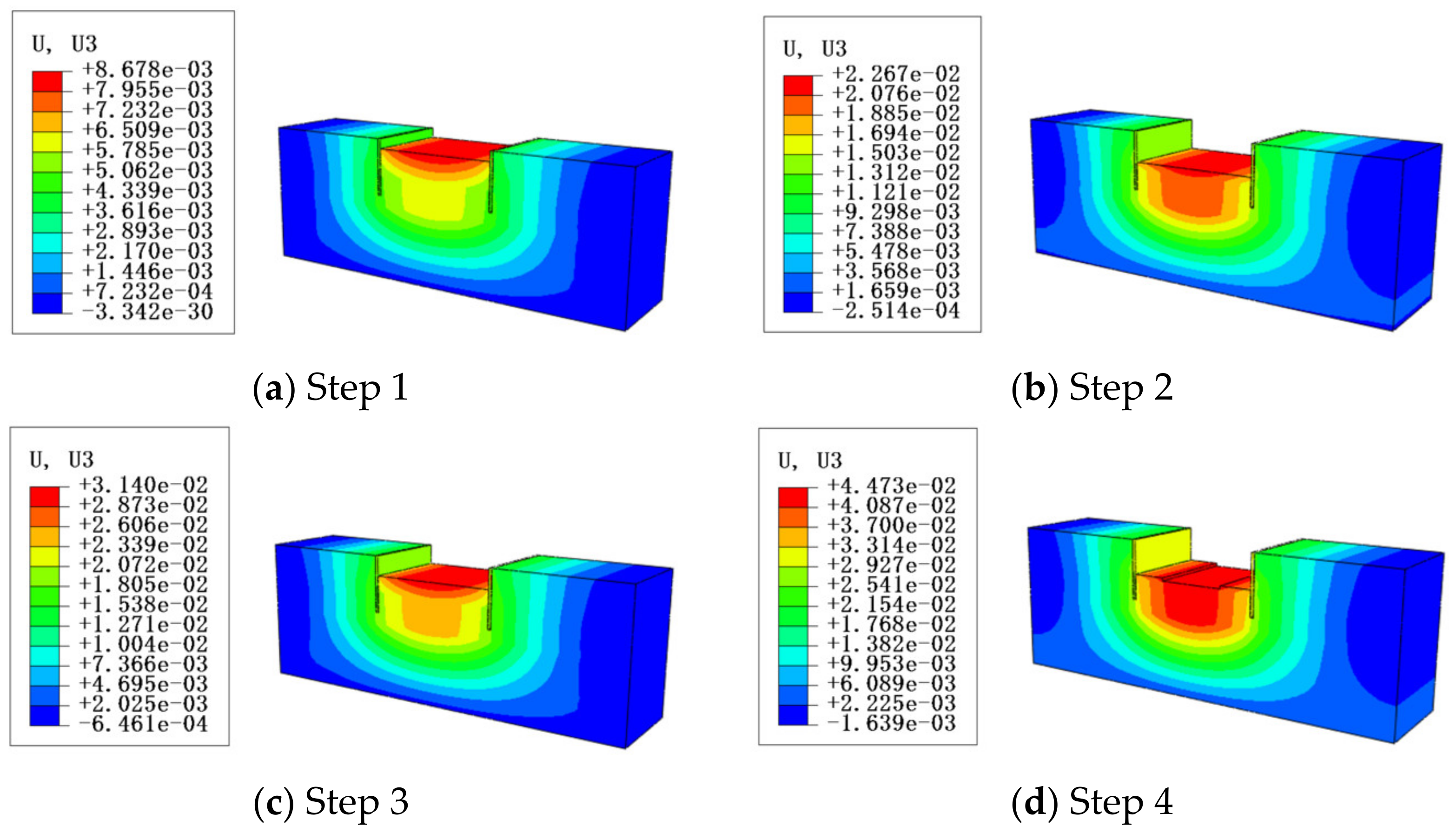
4.1. Vertical Displacement
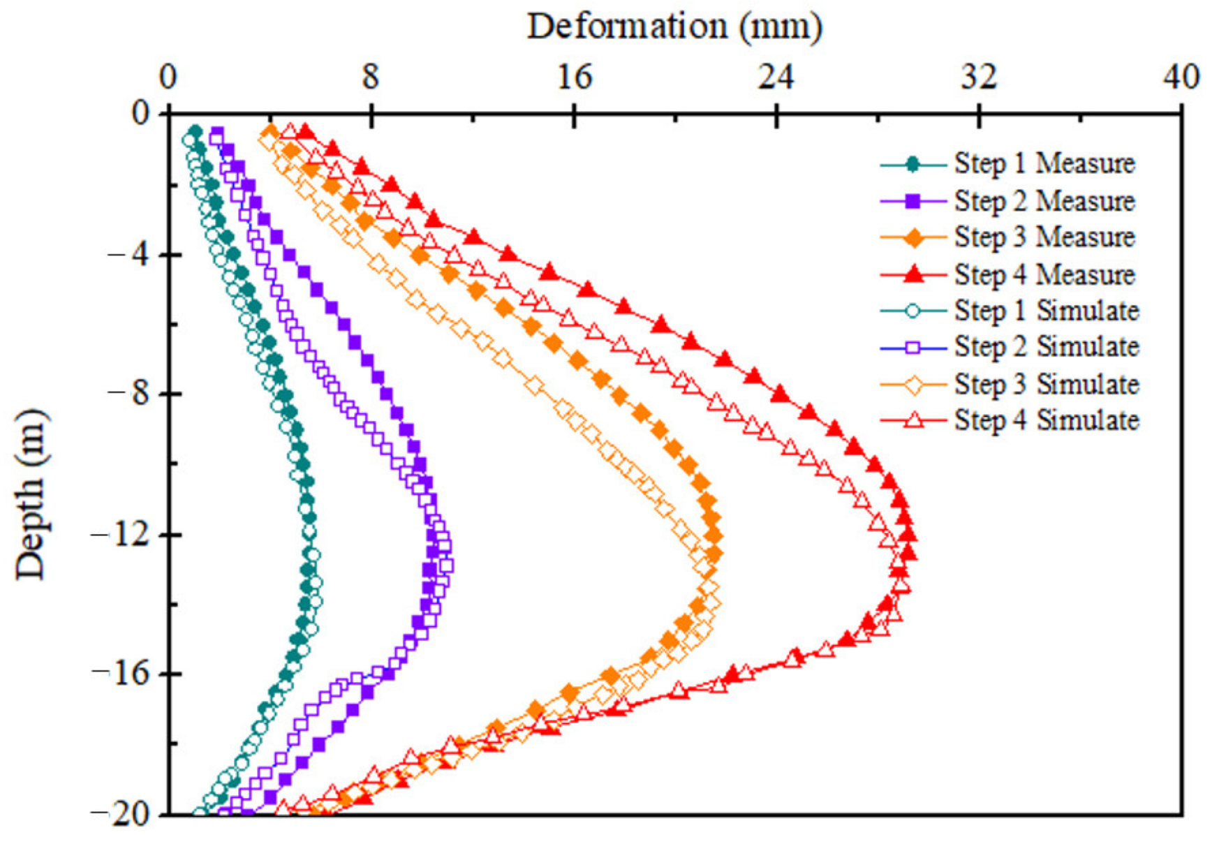
4.2. Displacement in the Diaphragm Wall
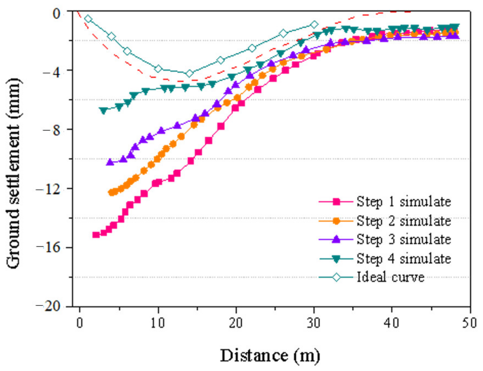
4.3. Ground Settlement
4.4. Influence of Parameters and Energy Consumption Analysis
5. Conclusions
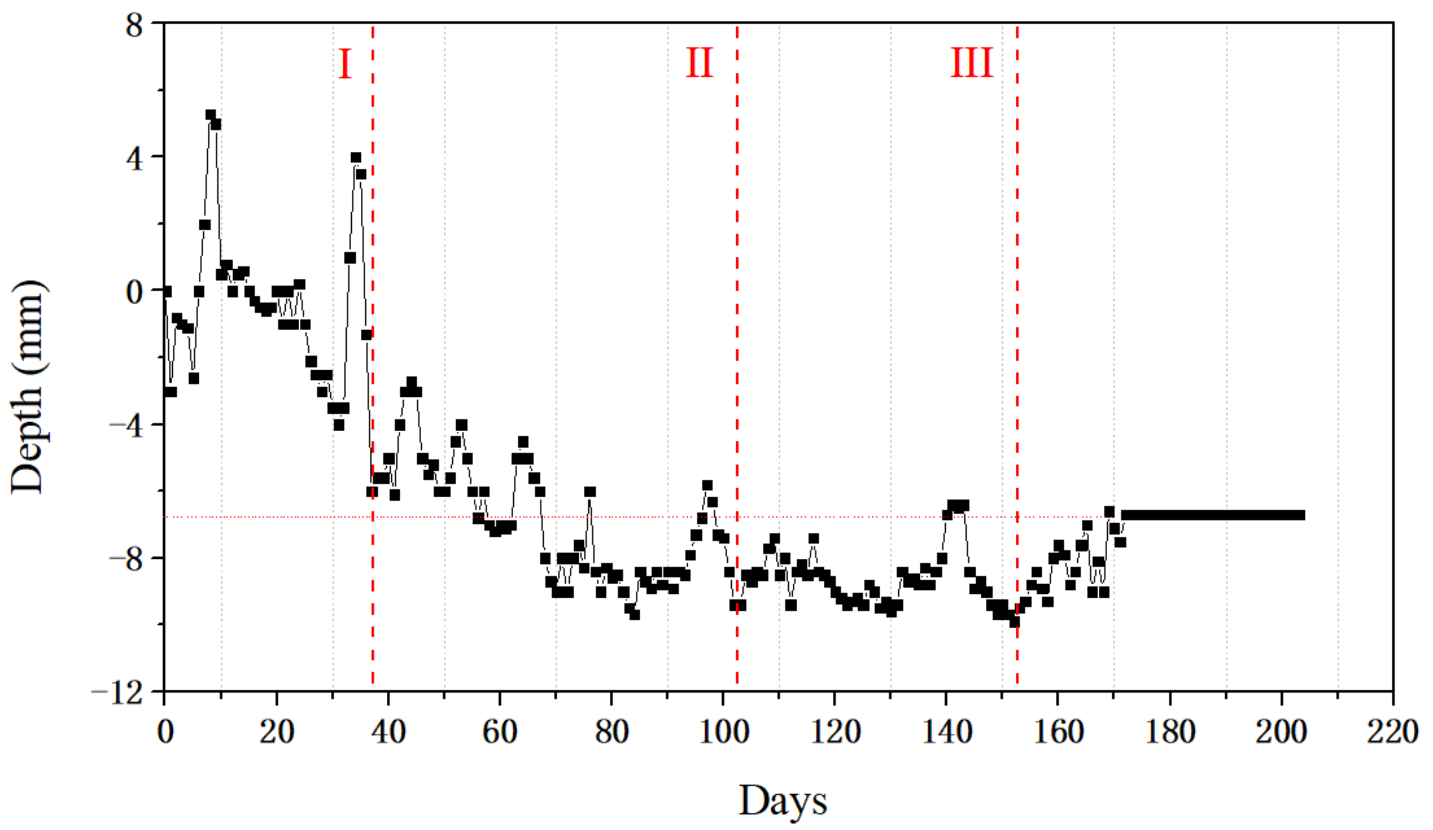
- The maximum deformation of the foundation pit bottom is 4.5 cm. The deformation of the foundation pit is within the allowable range, far from reaching the failure form. The uplift of the foundation pit bottom is steadily increased.
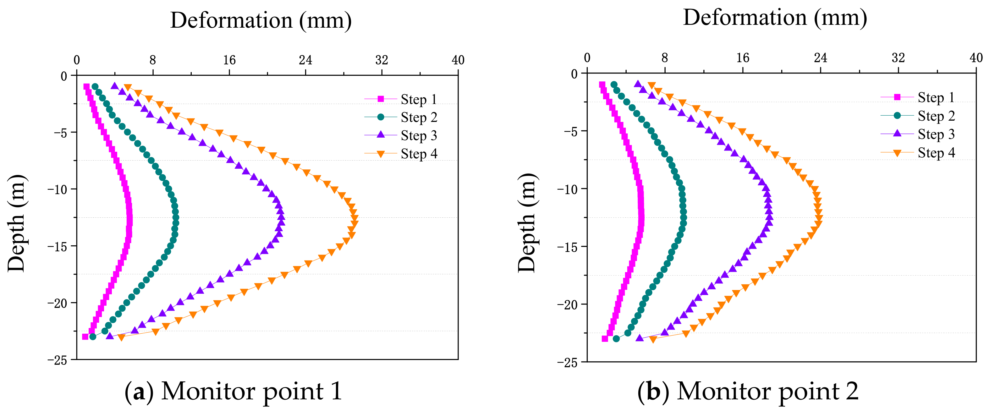
- The maximum horizontal displacement of each excavation is witnessed at approximately 10 m to 12 m of the diaphragm wall, and the largest deformation is 28 mm. The simulated value of the foundation pit is close to the actual monitoring value, but the friction and other interactions between the wall and soil need further study.
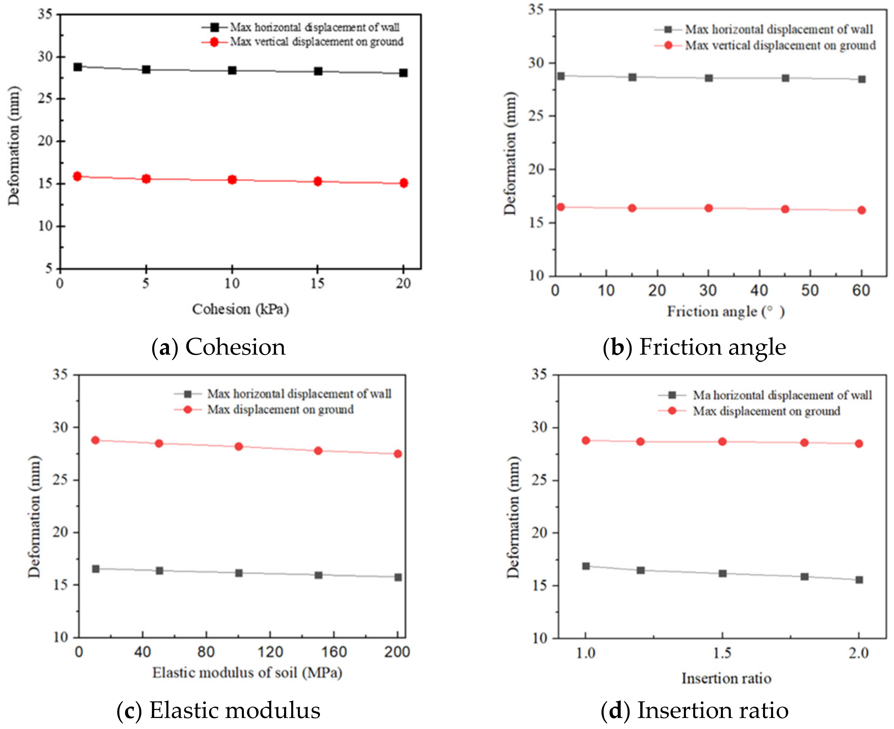
- The variation trend of ground settlement in the foundation pit under different excavation steps decreases along the direction away from the foundation pit. The maximum ground settlement is less than 16 mm. The value change of four parameters has little effect on the simulation results of the foundation pit, which proves that the relevant parameters of this simulation have certain applicability.
- This research simulated and monitored the whole cycle of foundation pit excavation, and contributes to the savings in energy consumption and limiting of carbon emissions.
Author Contributions
Funding
Institutional Review Board Statement
Informed Consent Statement
Data Availability Statement
Acknowledgments
Conflicts of Interest
References
- Cui, K.; Feng, J.; Zhu, C.Y. A study on the mechanisms of interaction between deep foundation pits and the pile foundations of adjacent skewed arches as well as methods for deformation control. Complexity 2018, 1, 6535123. [Google Scholar] [CrossRef]
- Ding, Z.; Jin, J.; Han, T. Analysis of the zoning excavation monitoring data of a narrow and deep foundation pit in a soft soil area. J. Geophys. Eng. 2018, 15, 1231–1241. [Google Scholar] [CrossRef]
- Editorial Department of China Journal of Highway and Transport. Review on China’s Subgrade Engineering Research. China J. Highw. Transp. 2021, 34, 1–49. [Google Scholar]
- Zhang, J.; Li, J.; Yao, Y.; Zheng, J.; Gu, F. Geometric Anisotropy Modeling and Shear Behavior Evaluation of Graded Crushed Rocks. Constr. Build. Mater. 2018, 183, 346–355. [Google Scholar] [CrossRef]
- Hou, S.; Chen, C.; Zhang, J.; Shen, H.; Gu, F. Thermal and mechanical evaluations of asphalt emulsions and mixtures for micro surfacing. Constr. Build. Mater. 2018, 191, 1221–1229. [Google Scholar] [CrossRef]
- Fredlund, D.G.; Krahn, J. Comparison of slope stability methods of analysis. Can. Geotech. J. 1997, 14, 429–439. [Google Scholar] [CrossRef]
- Gao, Y.; Zhang, Y.; Yang, Y.; Zhang, J.; Gu, F. Molecular dynamics investigation of interfacial adhesion between oxidized bitumen and mineral surfaces. Appl. Surf. Sci. 2019, 479, 449–462. [Google Scholar] [CrossRef]
- Huang, M.; Liu, X.R.; Zhang, N.Y.; Shen, Q.W. Calculation of foundation pit deformation caused by deep excavation considering influence of loading and unloading. J. Cent. South Univ. 2017, 24, 2164–2171. [Google Scholar] [CrossRef]
- Tang, Q.; Chu, J.M.; Wang, Y.; Zhou, T.; Liu, Y. Characteristics and factors influencing Pb(II) desorption from a Chinese clay by citric acid. Sep. Sci. Technol. 2016, 51, 2734–2743. [Google Scholar] [CrossRef]
- Chen, R.P.; Meng, F.Y.; Li, Z.C.; Ye, Y.H.; Ye, J.N. Investigation of response of metro tunnels due to adjacent large excavation and protective measures in soft soils. Tunn. Undergr. Sp. Technol. 2016, 58, 224–235. [Google Scholar] [CrossRef]
- Kammoun, Z.; Fourati, M.; Smaoui, H. Direct limit analysis-based topology optimization of foundations. Soils Found. 2019, 59, 1063–1072. [Google Scholar] [CrossRef]
- Chen, S.; Cui, J.; Liang, F. Centrifuge Model Investigation of Interaction between Successively Constructed Foundation Pits. Appl. Sci. 2022, 12, 7975. [Google Scholar] [CrossRef]
- Tang, Q.; Gu, F.; Gao, Y.F.; Inui, T.; Katsumi, T. Desorption Characteristics of Cr(III), Mn(II) and Ni(II) in Contaminated Soil Using Citric Acid and Citric Acid Containing Wastewater. Soils Found (JGS) 2018, 58, 50–64. [Google Scholar]
- Han, S.Y.; Yang, K.; Wei, X.; Yun, L.; Cheng, C. Analysis of the influence of inside and outside water level changes of foundation pit on stability of foundation. AER-Adv. Eng. Res. 2016, 99, 280–284. [Google Scholar]
- Xiong, B.L.; Wang, X.L.; Lu, C.J. High slope of prestressed anchor cable lattice beam reinforcement system 3D finite element analysis. Railw. Constr. 2010, 2, 67–70. (In Chinese) [Google Scholar]
- Jiang, N.; Zhang, Y.; Zhou, C.; Wu, T.; Zhu, B. Influence of Blasting Vibration of MLEMC Shaft Foundation Pit on Adjacent High-Rise Frame Structure: A Case Study. Energies 2020, 13, 5140. [Google Scholar] [CrossRef]
- Tang, Q.; Kim, H.J.; Endo, K.; Katsumi, T.; Inui, T. Size effect on lysimeter test evaluating the properties of construction and demolition waste leachate. Soils Found (JGS) 2015, 55, 720–736. [Google Scholar]
- Zhang, Y.; Tang, Q.; Chen, S.; Gu, F.; Li, Z.Z. Heavy metal adsorption of a novel membrane material derived from senescent leaves: Kinetics, equilibrium and thermodynamic studies. Membr. Water Treat. 2018, 9, 95–104. [Google Scholar]
- Tang, Q.; Zhang, Y.; Gao, Y.F.; Gu, F. Use of Cement-Chelated Solidified MSWI Fly Ash for Pavement Material: Mechanical and Environmental Evaluations. Can. Geotech. J. 2017, 54, 1553–1566. [Google Scholar] [CrossRef]
- Zhou, Y.; Pan, L.; Tang, Q.; Zhang, Y.; Yang, N.; Lu, C. Evaluation of carbonation effects on cement solidified contaminated soil used in road subgrade. Adv. Mater. Sci. Eng. 2018, 2018, 5271324. [Google Scholar] [CrossRef]
- Tang, Q.; Gu, F.; Chen, H.; Lu, C.; Zhang, Y. Mechanical Evaluation of Bottom Ash from Municipal Solid Waste Incineration Used in Road base. Adv. Civ. Eng. 2018, 5694908. [Google Scholar] [CrossRef]
- Zhang, J.; Gu, F.; Zhang, Y. Use of building-related construction and demolition wastes in highway embankment: Laboratory and field evaluations. J. Clean. Prod. 2019, 230, 1051–1060. [Google Scholar] [CrossRef]
- Gu, F.; Zhang, Y.; Tang, Q.; Lu, C.; Zhou, T. Remediation of Zn(II) and Cu(II) contaminated soil using citric acid and citric acid containing wastewater. Int. J. Civ. Eng. 2018, 16, 1607–1619. [Google Scholar] [CrossRef]
- Chu, W.; Calise, F.; Duić, N.; Østergaard, P.A.; Vicidomini, M.; Wang, Q. Recent Advances in Technology, Strategy and Application of Sustainable Energy Systems. Energies 2020, 13, 5229. [Google Scholar] [CrossRef]
- Van der Male, P.; Vergassola, M.; van Dalen, K.N. Decoupled Modelling Approaches for Environmental Interactions with Monopile-Based Offshore Wind Support Structures. Energies 2020, 13, 5195. [Google Scholar] [CrossRef]
- Hu, Y.; Yang, J.; Baniotopoulos, C. Study of the Bearing Capacity of Stiffened Tall Offshore Wind Turbine Towers during the Erection Phase. Energies 2020, 13, 5102. [Google Scholar] [CrossRef]
- Li, J.W.; Li, X.; Xiong, M.X.; Luo, H.F. Deformation monitoring and numerical simulation of retaining structure in subway station deep foundation pit. Electron. J. Geotech. Eng. 2016, 21, 2331–2340. [Google Scholar]
- Li, S.C.; Xie, C.; Liang, Y.H.; Qin, Y. Seepage flow model and deformation properties of coastal deep foundation pit under tidal influence. Math. Probl. Eng. 2018, 2018, 9714901. [Google Scholar] [CrossRef]
- Mangushev, R.A.; Osokin, A.I.; Garnyk, L.V. Experience in preserving adjacent buildings during excavation of large foundation pits under conditions of dense development. Soil Mech. Found. Eng. 2016, 53, 291–297. [Google Scholar] [CrossRef]
- Zhou, Y.; Su, W.J.; Ding, L.; Luo, H.; Love, P. Predicting safety risks in deep foundation pits in subway infrastructure projects: Support vector machine approach. J. Comput. Civ. Eng. 2017, 31, 04017052. [Google Scholar] [CrossRef]
- Zhu, C.; Zhang, K.; Tao, Z.G.; An, B.; He, M.; Xia, X.; Liu, J. Combined application of optical fibers and CRLD bolts to monitor deformation of a pit-in-pit foundation. Adv. Civ. Eng. 2019, 2019, 2572034. [Google Scholar]
- Zhu, C.; Yan, Z.H.; Lin, Y.; Xiong, F.; Tao, Z.G. Design and application of a monitoring system for a deep railway foundation pit project. IEEE Access 2019, 7, 107591–107601. [Google Scholar] [CrossRef]
- Ou, M.X.; Liu, X.R.; Shi, J.X. Earth pressure applied in retaining wall of deep foundation pit considering influence of unloading and deformation. Zhongnan Daxue Xuebao (Ziran Kexue Ban)/J. Cent. South Univ. (Sci. Technol.) 2012, 43, 669–674. [Google Scholar]
- Fan, S.; Song, Z.; Xu, T.; Wang, K.; Zhang, Y. Tunnel deformation and stress response under the bilateral foundation pit construction: A case study. Arch. Civ. Mech. Eng. 2021, 21, 1–19. [Google Scholar] [CrossRef]
- Tang, Q.; Liu, W.; Li, Z.Z.; Wang, Y.; Tang, X.W. Removal of Aqueous Cu(II) with Natural Kaolin: Kinetics and Equilibrium Studies. Environ. Eng. Manag. J. 2018, 17, 467–476. [Google Scholar]
- Kang, C.; Xu, R.; Ying, H.W.; Lin, C.; Gan, X. Simplified method for calculating ground lateral displacement induced by foundation pit excavation. Eng. Comput. 2020. ahead-of-print. [Google Scholar]
- Zheng, Y.; Hu, Z.; Ren, X.; Wang, R.; Zhang, E. The influence of partial pile cutting on the pile-anchor supporting system of deep foundation pit in loess area. Arab. J. Geosci. 2021, 14, 1–12. [Google Scholar] [CrossRef]
- Wu, J.; Peng, L.; Li, J.; Zhou, X.; Sun, J. Rapid safety monitoring and analysis of foundation pit construction using unmanned aerial vehicle images. Autom. Constr. 2021, 128, 103706. [Google Scholar] [CrossRef]
- Zhao, X.Y.; Zhang, Y.W.; Ding, H.; Chen, L.Q. Vibration suppression of a nonlinear fluid-conveying pipe under harmonic foundation displacement excitation via nonlinear energy sink. Int. J. Appl. Mech. 2018, 10, 1850096. [Google Scholar] [CrossRef]
- Zhao, Z.; Lei, Y. Mechanism analysis of uncovering coal in crosscut and gas outburst based on flac3d. J. Coast. Res. 2020, 103, 333–338. [Google Scholar] [CrossRef]
- Kim, K.Y.; Lee, D.S.; Cho, J.; Jeong, S.S.; Lee, S. The effect of arching pressure on a vertical circular shaft. Tunn. Undergr. Space Technol. 2013, 37, 10–21. [Google Scholar] [CrossRef]
- Fang, Y.S.; Ishibashi, I. Static earth pressures with various wall movements. J. Geotech. Eng. 1986, 112, 317–333. [Google Scholar] [CrossRef]
- Sarmadi, H.; Karamodin, A. A novel anomaly detection method based on adaptive Mahalanobis-squared distance and one-class kNN rule for structural health monitoring under environmental effects. Mech. Syst. Signal Process. 2020, 140, 106495. [Google Scholar] [CrossRef]
- Liu, Z.P.; Liu, J.; Bian, K.; Ai, F. Three-dimensional limit equilibrium method based on a TIN sliding surface. Eng. Geol. 2019, 262, 105325. [Google Scholar] [CrossRef]
- Wang, Y.K.; Sun, S.W.; Liu, L. Mechanism, Stability and Remediation of a Large Scale External Waste Dump in China. Geotech. Geol. Eng. 2019, 37, 5147–5166. [Google Scholar] [CrossRef]
- Zheng, Y.; Chen, C.; Liu, T.; Zhang, H.; Sun, C. Theoretical and numerical study on the block-flexure toppling failure of rock slopes. Eng. Geol. 2019, 263, 105309. [Google Scholar] [CrossRef]
- Cao, S.; Xia, L.X. Conscientiousness mediates the link between brain structure and consideration of future consequence. Neuropsychologia 2020, 141, 107435. [Google Scholar] [CrossRef]
- Motta, E. Generalized Coulomb active-earth pressure for distanced surcharge. J. Geotech. Eng. 1994, 120, 1072–1079. [Google Scholar] [CrossRef]
- Kshirsagar, N.A. Rational use of medicines: Cost consideration & way forward. Indian J. Med. Res. 2016, 144, 502. [Google Scholar]
- Song, W.; Veenstra, J.A.; Perrimon, N. Control of lipid metabolism by tachykinin in Drosophila. Cell Rep. 2014, 9, 40–47. [Google Scholar] [CrossRef]
- Finno, R.J.; Blackburn, J.T.; Roboski, J.F. Three-dimensional effects for supported excavations in clay. J. Geotech. Geoenviron. Eng. 2007, 133, 30–36. [Google Scholar] [CrossRef]
- Gnanapragasam, N. Active earth pressure in cohesive soils with an inclined ground surface. Can. Geotech. J. 2000, 37, 171–177. [Google Scholar] [CrossRef]
- Peters, G.P.; Weber, C.L.; Guan, D.; Hubacek, K. China’s growing CO2 emission–A race between increasing consumption and efficiency gains. Environ. Sci. Technol. 2007, 41, 17. [Google Scholar] [CrossRef] [PubMed]
- Marinković, S.; Radonjanin, V.; Malešev, M.; Ignjatović, I. Comparative environmental assessment of natural and recycled aggregate concrete. Waster Manag. 2010, 30, 2255–2264. [Google Scholar] [CrossRef] [PubMed]
- Fambri, G.; Badami, M.; Tsagkrasoulis, D.; Katsiki, V.; Giannakis, G.; Papanikolaou, A. Demand Flexibility Enabled by Virtual Energy Storage to Improve Renewable Energy Penetration. Energies 2020, 13, 5128. [Google Scholar] [CrossRef]
- Kanz, O.; Reinders, A.; May, J.; Ding, K. Environmental Impacts of Integrated Photovoltaic Modules in Light Utility Electric Vehicles. Energies 2020, 13, 5120. [Google Scholar] [CrossRef]


| Soil Layer Name | Thickness of Soil Layer (m) | Density (g/cm3) | Cohesion (kPa) | Friction Angle (°) |
|---|---|---|---|---|
| Miscellaneous fill | 4.2 | 1.88 | 10 | 8 |
| Silt | 2.2 | 1.89 | 26.8 | 14.5 |
| Silt mixed with silty clay | 6.9 | 1.75 | 13.5 | 12.3 |
| Clay | 2.5 | 1.95 | 47.4 | 15.7 |
| Silty clay | 2.6 | 1.92 | 34.8 | 16.3 |
| Sandy clay | 5.7 | 1.86 | 7.6 | 24.1 |
| Silt | 7.3 | 1.87 | 2.8 | 14.3 |
| Soil Layer Name | Thickness of Soil Layer (m) | Density (g/cm3) | Cohesion (kPa) | Friction Angle (°) | Elastic Modulus (MPa) |
|---|---|---|---|---|---|
| Silty clay | 5 | 19.2 | 34.8 | 16.3 | 25 |
| Silty sand | 8 | 18.7 | 2.8 | 28.9 | 50 |
| Silty clay | 37 | 19.6 | 45.4 | 16.2 | 30 |
| Geometric Properties | Density (g/cm3) | Elastic Modules (MPa) | |
|---|---|---|---|
| Steel support | D = 800 mm, t = 20 mm | 7.8 | 210,000 |
| Diaphragm wall | D = 800 mm, spacing 1000 mm | 2.4 | 30,000 |
| Soil | (None) | <2 | 30 |
| Reinforcement | (None) | >2 | 300 |
Publisher’s Note: MDPI stays neutral with regard to jurisdictional claims in published maps and institutional affiliations. |
© 2022 by the authors. Licensee MDPI, Basel, Switzerland. This article is an open access article distributed under the terms and conditions of the Creative Commons Attribution (CC BY) license (https://creativecommons.org/licenses/by/4.0/).
Share and Cite
Chen, J.; Xu, Q.; Luo, X.; Tian, A.; Xu, S.; Tang, Q. Safety Evaluation and Energy Consumption Analysis of Deep Foundation Pit Excavation through Numerical Simulation and In-Site Monitoring. Energies 2022, 15, 7099. https://doi.org/10.3390/en15197099
Chen J, Xu Q, Luo X, Tian A, Xu S, Tang Q. Safety Evaluation and Energy Consumption Analysis of Deep Foundation Pit Excavation through Numerical Simulation and In-Site Monitoring. Energies. 2022; 15(19):7099. https://doi.org/10.3390/en15197099
Chicago/Turabian StyleChen, Ji, Qi Xu, Xinyu Luo, Angran Tian, Sujing Xu, and Qiang Tang. 2022. "Safety Evaluation and Energy Consumption Analysis of Deep Foundation Pit Excavation through Numerical Simulation and In-Site Monitoring" Energies 15, no. 19: 7099. https://doi.org/10.3390/en15197099
APA StyleChen, J., Xu, Q., Luo, X., Tian, A., Xu, S., & Tang, Q. (2022). Safety Evaluation and Energy Consumption Analysis of Deep Foundation Pit Excavation through Numerical Simulation and In-Site Monitoring. Energies, 15(19), 7099. https://doi.org/10.3390/en15197099