Article

Research on Space Vector Overmodulation Technology of Two-Level PWM Converters

1
State Key Laboratory of Reliability and Intelligence of Electrical Equipment, Hebei University of Technology, Tianjin 300131, China
2
Key Laboratory of Electromagnetic Field and Electrical Apparatus Reliability of Hebei Province, Hebei University of Technology, Tianjin 300131, China
3
School of Automation and Electrical Engineering, Tianjin University of Technology and Education, Tianjin 300222, China
*
Author to whom correspondence should be addressed.
Energies 2022, 15(19), 7086; https://doi.org/10.3390/en15197086
Submission received: 24 August 2022 / Revised: 18 September 2022 / Accepted: 21 September 2022 / Published: 27 September 2022

Abstract

:
In this paper, the characteristics of the voltage transfer ratio (VTR) and low-order harmonics of the major modern space vector overmodulation strategies for two-level PWM converters are discussed under different VTRs, and the complexity of the modulation algorithm is subsequently elaborated. First, the principles of these overmodulation strategies are summarized. After that, the accuracy and linearization of the VTR are obtained using the Fourier transform analysis, and the relationship between the main low harmonic components and the VTR is obtained in the same way. All the analysis results are verified through experiments. In addition, the merits and demerits of these overmodulation strategies and applications are revealed by comparing the simplicity of their modulation algorithm, digitization, and other characteristics. Finally, this paper reveals the essence of space vector overmodulation strategies. The results facilitate the design, performance prediction, and development of high-performance overmodulation strategies, as well as the transplantation of space vector overmodulation strategies into different converter topologies.

1. Introduction

With the rapid development of power electronic technology and further improvement of control theory, motor speed regulation technology is maturing. Overmodulation is an effective method to achieve the high output voltage magnitude of the converter without changing the topology structure [1]. In addition, it can expand the steady-state operation area of the motor, which has invariable dominance [2]. In the wide range of speed regulation systems of the motors driven by two-level converters, the technology of overmodulation is relatively mature [3,4]. Compared with the method of adding a boost circuit, only the control or modulation strategy of the converters is required to change, which is easy to implement in engineering [5].
To improve the voltage transfer ratio (VTR) of the PWM converters, many scholars began to study the overmodulation technique in the early 1990s. Considering the required harmonic characteristics and control complexity of power converters, various strategies have been continuously proposed.
The overmodulation techniques can be divided into two categories following the degree of their modulation effect: one is the minimum-phase-error PWM (MPEPWM) [6,7], which only changes the magnitude of the reference voltage without changing the phase. In contrast, both the magnitude and phase of the reference voltage are changed in the minimum-magnitude-error PWM (MMEPWM) [8,9]. In addition, overmodulation techniques can be divided into two categories based on their modulation principle: In [10,11], a PWM overmodulation technique was proposed to improve the VTR realized by adjusting the reference output voltage magnitude (i.e., the magnitude of the modulating wave), and the authors also discussed the harmonic components. Theoretically, due to the modulating wave adopting the standard sine function, only when the magnitude of the reference modulating waveform is infinite can the fundamental waveform magnitude be obtained, which corresponds to a square modulated waveform. This result deteriorates the fundamental magnitude of the output voltage. To address this problem, the authors added an inverse gain compensation link to achieve the desired output voltage. In addition, the problems caused by overmodulation severely threaten the system reliability of the hybrid modular multilevel converter (MMC). The authors of [12] introduced a structure of self-balancing branches into the hybrid MMC to eliminate voltage deviations. In another study [13], the authors proposed an approach of optimizing the SHCC reference to realize voltage balancing, which minimizes the power losses caused by the SHCC injection. Another technique is the space vector overmodulation technique, which improves the VTR by adjusting the magnitude and phase of the reference output voltage vector [5,6,8,14,15,16]. In [5], a multimode space vector overmodulation was proposed based on three-degree-of-freedom converters. Bolognani proposed a space vector strategy based on a six-step mode for high dynamic performance and high switching frequency drives [8]. In [14], the actual output voltage of a current controller was selected as the closest voltage vector at the same angle as that required by the current error compensator. In [16], a novel control technology combining discontinuous pulse width modulation (DPWM) and overmodulation technology was proposed to better utilize direct current. Compared with the PWM overmodulation, the space vector overmodulation has one more modulation degree, which makes it more flexible [17]. Therefore, a remarkable number of studies in the field of two-level PWM converter overmodulation have been dedicated to space vector overmodulation in recent years.
Higher voltage utilization is related to the external performance of the overmodulation strategy. However, whether or not it can be consistent with the command voltage is of greater significance. In other words, an excellent overmodulation strategy should have a smaller low-harmonic distortion rate and more accurate VTR, so the components of harmonic can be used for evaluation. Generally, the harmonic components of the output voltage can be calculated using the fast Fourier transform (FFT) method [7,10,18,19], and the double Fourier integral transform method also offers a possibility to analyze the harmonic components [19,20,21,22,23]. However, since the switching frequency is much larger than the fundamental frequency, a single Fourier integral transform was used in this paper to evaluate the low-order harmonic components [24,25,26,27], and the analysis was verified through experiments.
In this paper, the modern space vector overmodulation strategies based on two-level converters are discussed. First, the significance, application, and classification of overmodulation and the method of characteristic analysis are briefly introduced in Section 1. In Section 2, the basic principle of each space vector overmodulation strategy is summarized. The linearity of VTR, low-order harmonic components, and the complexity of the modulation algorithm are evaluated in Section 3 with the single Fourier transform method. In Section 4, a test system based on two-level converters is built, and the correctness of the theoretical analysis is verified through experiments. Section 5 compares the characteristics of the space vector overmodulation technique. Finally, the essence of the space vector overmodulation strategy is revealed in Section 6.

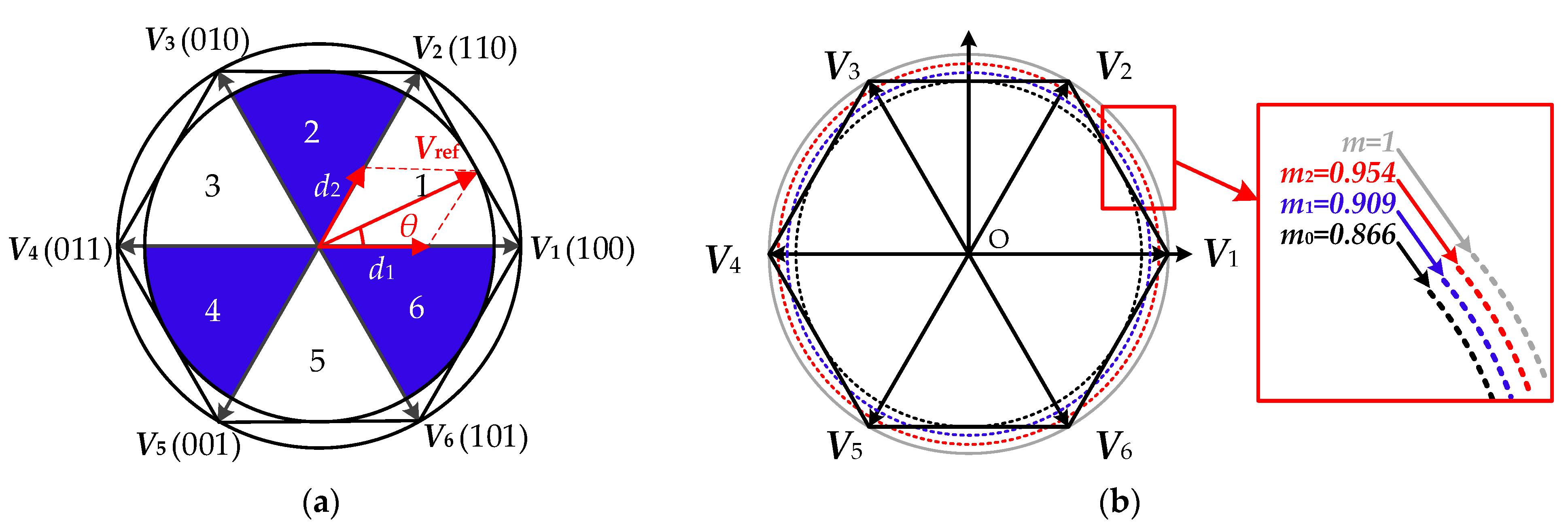
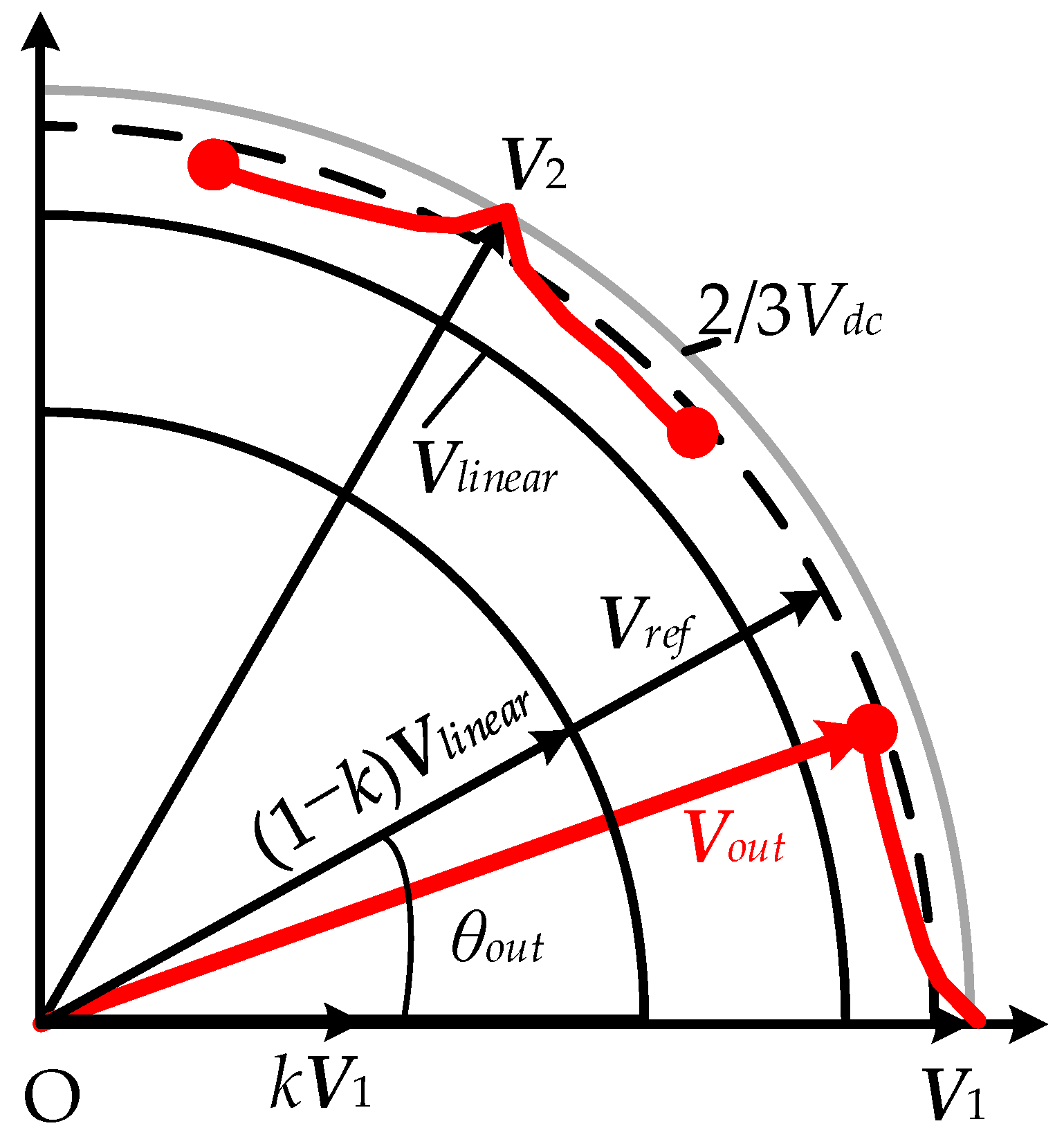
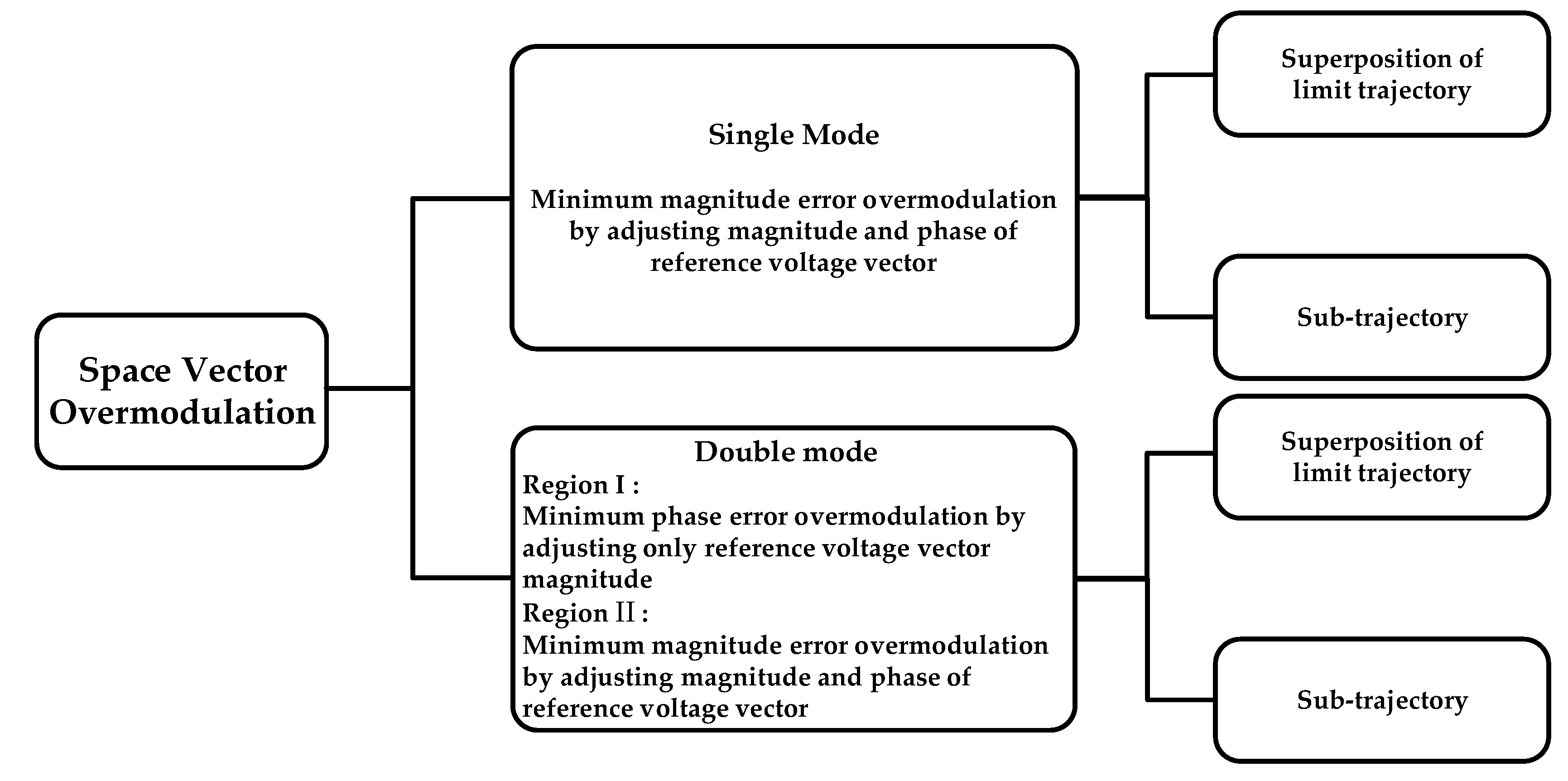
2. Space Vector Overmodulation Technology of Two-Level PWM Converters

To simplify the analysis, the reference VTR m, output fundamental VTR mout_1, space vector Vref corresponding to the reference output voltage, and the six effective voltage vectors Vl(l = 1, 2, 3, 4, 5, 6) are defined as:
  m = V ref 2 3 V dc ,   m out _ 1 = V out _ 1 2 3 V dc
V ref = V ref e j θ out
V l = 2 3 V dc e j π l 1 3
where Vdc is the DC bus voltage, Vout_1 is the fundamental magnitude of the output voltage, and Vref is the magnitude of the reference output voltage vector; the output phase θout = 2πfoutt + φ0, fout is the reference output voltage frequency, and φ0 is the reference output voltage initial phase angle.
Achieving the desired reference voltage vector by combining eight different voltage vectors of the two-level converter is the basic principle of SVPWM. Figure 1 shows the vector diagram of the two-level converters. Ignoring the effects of nonlinearities such as switching harmonics and the dead zones of the converters, the SVPWM exhibits excellent linear VTR in the linear modulation region. The output voltage of harmonic components is almost zero (the linear modulation region is the inner circle in Figure 1).
When the converter operates outside the linear modulation region (the region between the inner and outer circles in Figure 1), the space vector overmodulation strategy is utilized to obtain the reference voltage magnitude, but the output voltage contains some low-order harmonics.
There are four widely used strategies in the space vector overmodulation technique: strategy A is based on the dual-mode space vector overmodulation of sub-trajectory, strategy B adopts the single-mode space vector overmodulation of sub-trajectory, strategy C uses the dual-mode space vector overmodulation of superimposed limit trajectory, and strategy D is grounded on the single-mode space vector overmodulation of limit trajectory superposition.

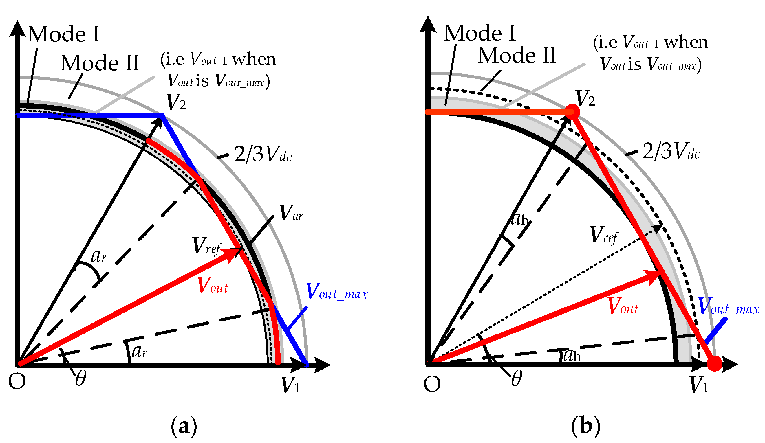
2.1. Strategy A: Dual-Mode Space Vector Overmodulation Based on Sub-Trajectory

A dual-mode space vector overmodulation strategy based on sub-trajectory was proposed in the literature [6], as shown in Figure 2. The strategy distinguished the overmodulation region into two intervals of 0.866 < m ≤ 0.909 and 0.909 < m ≤ 0.954, which are called the overmodulation regions I and II, respectively.
The upper bound of the overmodulation is the maximum output voltage vector Vout_max with double effective vector synthesis modulation, whereas the lower bound is the maximum linear output voltage vector Vlinear_max with a double effective vector and zero vector synthesis modulation. The VTR m0 corresponding to Vlinear_max is 0.866, while the m1 corresponding to Vout_max is 0.909. The upper-limit vector of the overmodulation region II is the output voltage vector of a two-level inverter with single effective vector modulation, and the corresponding VTR m2 is 0.954.
The first sector is used as an example, when the two-level converter operates in the overmodulation region I, as shown in Figure 2a. The output voltage vector Vout is a segmented combination of the Vout_max and the compensation output voltage vector Var, i.e.,
V out = V ar   , π 3 l 1 θ out < π 3 l 1 + a r     π 3 l a r θ out < π 3 l   V out _ max , π 3 l 1 + a r θ out < π 3 l a r
where Var and Vout_max are expressed as follows:
V ar = V ar e j θ out = V dc 3 cos π / 6 a r e j θ out V out _ max = V out _ max e j θ out = V dc 3 cos π / 6 θ out e j θ out
In the above equations, ar is the dividing angle of the overmodulation region I. When the angle θ between the reference output voltage vector and the adjacent effective voltage vector is less than ar, Vout is equal to Var; when this is greater than ar, Vout is equal to Vout_max.
When the two-level converter operates in the overmodulation region II, as shown in Figure 2b, Vout is the segmented combination of Vap and the adjacent effective voltage vector Vl, i.e.,
V out = V l   , 0 θ out < π 3 l 1 + a h V ap   , π 3 l 1 + a h θ out < π 3 l a h V l + 1   , π 3 l a h θ out < π 3 l
where Vap and ap are expressed as follows:
V ap = V dc 3 cos π / 6 a p e j a p + l 1 π 3
a p = θ out π / 3 l 1 a h 1 6 a h / π
In these equations, ah is the dividing angle of the overmodulation region II. When the angle θ between the reference output voltage vector and the adjacent effective voltage vector is less than ah, Vout is equal to Vl or Vl+1; when θ is greater than or equal to ah, Vout is equal to Vap.

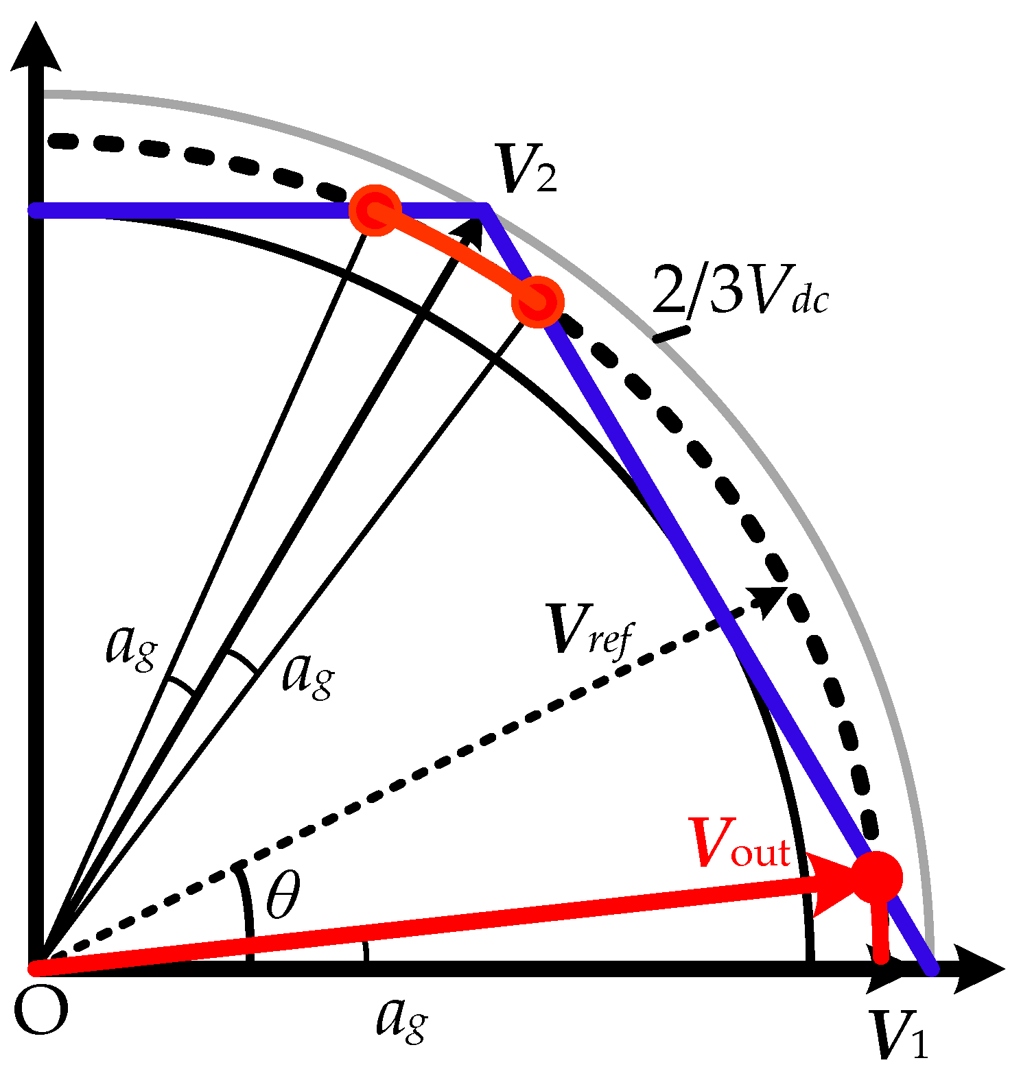
2.2. Strategy B: Single-Mode Space Vector Overmodulation Based on Sub-Trajectory

A single-mode space vector overmodulation strategy based on sub-trajectory was proposed in the literature [8]. This space vector overmodulation strategy no longer divides the overmodulation region. When the two-level converter operates in the overmodulation region, as shown in Figure 3, taking the first sector as an example, the Vout can be expressed as follows:
V out = V ref   , π 3 l 1 θ out < π 3 l 1 + a g V ref e j a g + π 3 l 1 , π 3 l 1 + a g   θ out < π 3 l π 6 V ref e j π 3 l a g   , π 3 l π 6   θ out < π 3 l a g   V ref   , π 3 l a g   θ out < π 3 l
on the basis of this geometric relationship, Vref and ag are expressed as follows:
V ref = V dc 3 cos π / 6 a g

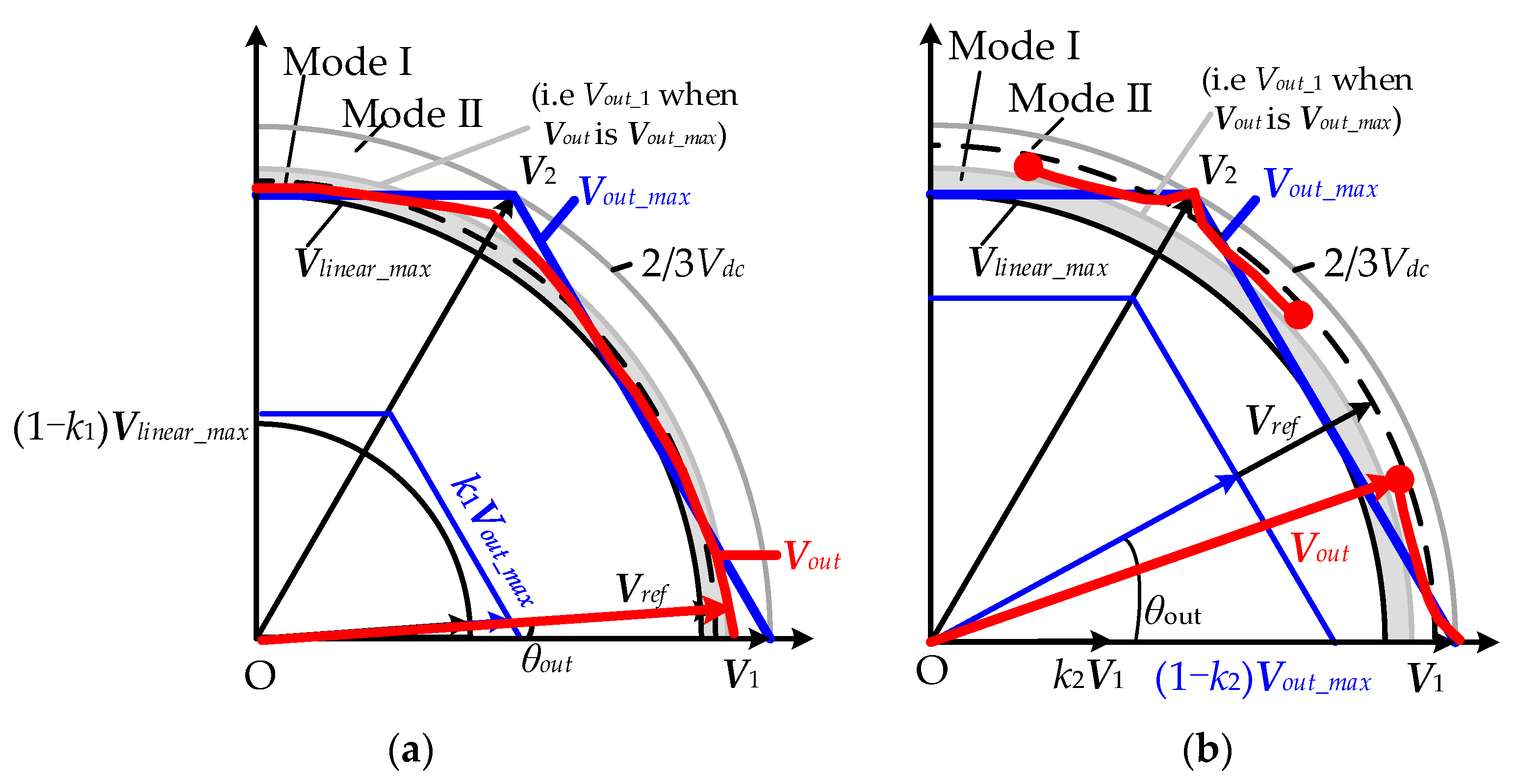
2.3. Strategy C: Dual-Mode Space Vector Overmodulation Based on Limit Trajectory Superposition

A dual-mode space overmodulation strategy based on limit trajectory superposition was proposed in the literature [7], as shown in Figure 4. This strategy also divides the overmodulation region into two intervals, and the boundary curve is still the hexagonal trajectory corresponding to Vlinear_max.
When the VSI runs in the overmodulated region I, as shown in Figure 4a, Vout is synthesized by Vlinear_max and Vout_max and linearly weighted, i.e.,
V out = k 1 V out _ max + ( 1 k 1 ) V linear _ max
the weighted coefficient k1 is expressed as follows:
k 1 = m m 0 m 1 m 0
When the VSI runs in overmodulated region II, as shown in Figure 4b, Vout is synthesized by Vout_max and Vl and linearly weighted, i.e.,
V out = k 2 V l + ( 1 k 2 ) V out _ max
the weighted coefficient k2 is expressed as follows:
k 2 = m m 1 m 2 m 1
The dual-mode space overmodulation strategy based on limit trajectory superposition is realized by the linear superimposed principle.

2.4. Strategy D: Single-Mode Space Vector Overmodulation Based on Limit Trajectory Superposition

A single-mode overmodulation strategy based on limit trajectory superposition was proposed in the literature [9], as shown in Figure 5. Vout in the whole overmodulation region is synthesized by Vlinear_max, and Vl linearly weighted, i.e.,
V out = k V l + ( 1 k ) V linear _ max
the weighted coefficient k is expressed as follows:
k = m m 0 m 2 m 0

3. Characteristics of Space Vector Overmodulation Technology

3.1. VTR

The output voltage magnitude and low-order harmonic components are the key indexes to evaluate the performance of the overmodulation strategy. Therefore, an excellent evaluation of the overmodulation strategy should have an accurate reference output voltage (i.e., the fundamental VTR mout_1 is equal to the VTR m), and the output voltage low-order harmonic components should be almost zero (i.e., the minimum THD) throughout the overmodulation region. The VTR and low-order harmonics of the above space vector overmodulation strategies are analyzed in detail, as described below.
The output voltage is affected by both the modulation wave and the carrier wave, so the output voltage spectrum can be accurately obtained by using a double Fourier integral transform [19,20,21,22,23]. However, in general, the carrier frequency is not considered in a low-order harmonic analysis since the carrier frequency is much larger than the modulation wave. Therefore, the fundamental magnitude of the output voltage and the low-order harmonic components are calculated by using a single Fourier integral transform [24,25,26,27].

3.1.1. Strategy A: Dual-Mode Space Vector Overmodulation Based on Sub-Trajectory

According to the principle of this strategy, the output fundamental voltage magnitude Vout_1 and mout_1 in the overmodulation region I can be obtained by using a single Fourier integral transform as follows:
V out _ 1 = V dc 2 π 2 3 ln 1 + cos ( π / 3 + a r ) 1 cos ( π / 3 + a r ) + 4 3 a r cos ( π / 6 a r )
  m out _ 1 = 3 4 π 2 3 ln 1 + cos ( π / 3 + a r ) 1 cos ( π / 3 + a r ) + 4 3 a r cos ( π / 6 a r )
From Equation (18), it can be seen that mout_1 has a nonlinear relationship with the boundary angle ar in the overmodulation region I, as shown in Figure 6. To obtain the linearized output between the fundamental output voltage and the reference output voltage in the overmodulation region I, the approximate linear function of m and ar is expressed as follows:
  a r = 38.3911 × m   +   33.7703 ;   0.866 m < 0.8683 9.4720 × m   +   8.6598         ;   0.8683 m < 0.9065 29.3911 × m   +   26.7165 ;   0.9065 m < 0.909
Vout_1 and mout_1 of the overmodulation region II can be expressed as follows:
V out _ 1 = V dc 2 π 8 sin ( a h ) + 4 3 cos ( π 6 a h ) + D 1
  m out _ 1 = 3 4 π 8 sin ( a h ) + 4 3 cos ( π 6 a h ) + D 1
where
D 1 = π 3 + a h 2 π 3 a h 2 3 cos ( π 3 + θ out π / 3 a h 1 6 a h / π ) sin ( π 3 + θ out π / 3 a h 1 6 a h / π ) e j p θ out d θ out
It can be seen from Equation (21) that mout_1 is nonlinearly related to ah in the overmodulation region II, as shown in Figure 7.
To obtain the linearized output of fundamental output voltage and the reference output voltage of the overmodulated region II, the approximate linear function of m with respect to the division angle ah is expressed as follows:
  a h = 6.667 × m 6.0567 ; 0.9089 m < 0.9360 11.7171 × m 10.7844 ; 0.9360 m < 0.9527 44.8611 × m 42.3142 ; 0.9513 m < 0.9549
The overmodulation strategy obtains the reference output voltage accurately by using the segmented processing of the nonlinear numerical relationship between the VTR and ah, so as to realize the linearization of the fundamental component and the output VTR in the overmodulation region [18].

3.1.2. Strategy B: Single-Mode Space Vector Overmodulation Based on Sub-Trajectory

Following the principle of this strategy, the output fundamental voltage magnitude in the overmodulation region can be obtained by using the single Fourier integral transform as follows:
V out _ 1 = 2 3 V dc π a g cos π 6 a g + cos π 3 + a g + tan ( π 6 a g ) 1 cos π 6 a g
Substituting Equation (10) into Equation (24), the relationship between mout_1 and m can be obtained as follows:
  m out _ 1 = 3 π 2 m π / 6 arccos 3 2 m + 4 m 2 3
It can be seen from Equation (25) that mout_1 has a nonlinear relationship with m.

3.1.3. Strategy C: Dual-Mode Space Vector Overmodulation Based on Limit Trajectory Superposition

The magnitude of the output fundamental voltage in overmodulation regions I and II is:
V out _ 1 = V dc 2 π 2 3 ln 3 k 1 + 2 3 3 π ( 1 k 1 )
V out _ 1 = V dc 2 π 4 k 2 + 2 3 ln 3 ( 1 k 2 )
Substituting Equation (12) and Equation (14) into Equation (26) and Equation (27), respectively, mout_1 can be expressed as follows:
  m out _ 1 = m
It can be seen from Equation (28) that overmodulation strategy C can accurately obtain the reference output voltage.

3.1.4. Strategy D: Single-Mode Space Vector Overmodulation Based on Limit Trajectory Superposition

The magnitude of the output fundamental voltage and the output fundamental VTR are expressed as follows:
V out _ 1 = V dc 2 π [ 4 k + ( 1 k ) 2 3 π 3 ]
Substituting Equation (16) into Equation (29), mout_1 can be expressed as Equation (28), which shows that overmodulation strategy D can accurately obtain the reference output voltage.
Using the data from Figure 6 and Figure 7, and Equations (18), (21), (25), (26) and (28), the relationship between the VTR and the fundamental VTR of each overmodulation strategy can be obtained as shown in Figure 8.
It can be seen from the diagram that overmodulation strategy A can obtain the approximate linearity of the fundamental VTR and the reference VTR after the approximate linearization of Equations (19) and (23). The fundamental VTR of strategy B is nonlinear with the voltage modulation ratio, and the maximum VTR cannot be obtained. Overmodulation strategies C and D can accurately obtain the fundamental magnitude of output voltage in the overmodulation region.

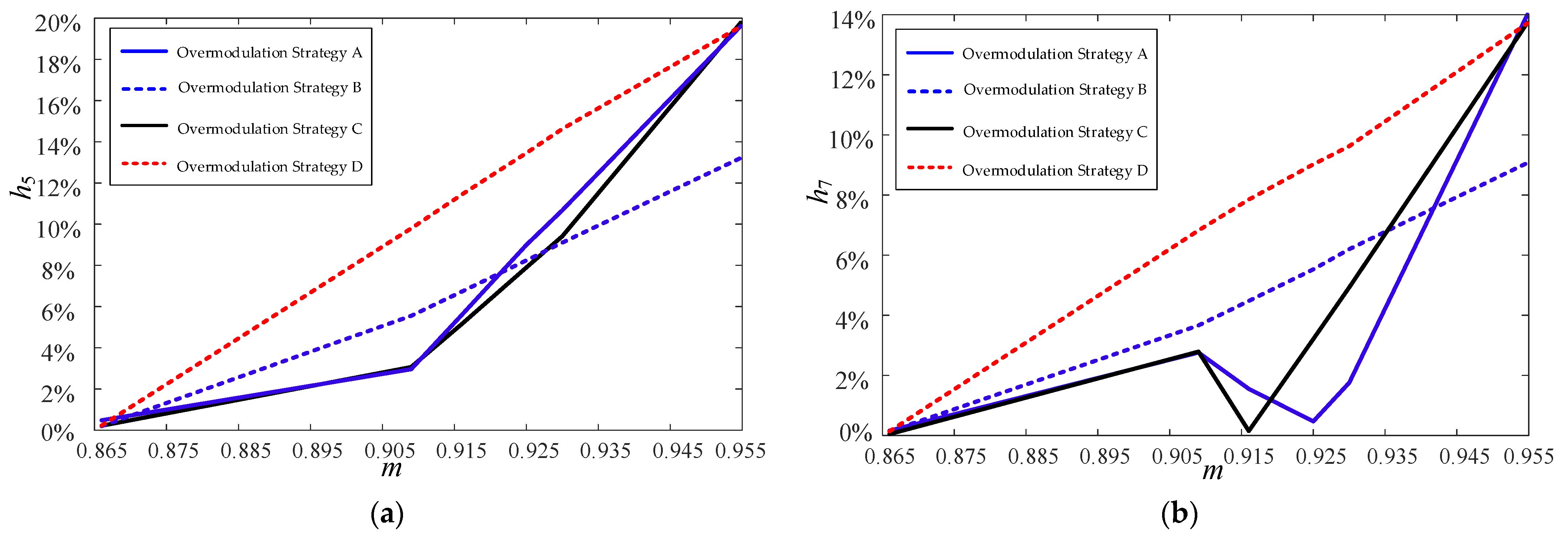
3.2. Low-Order Harmonic Components
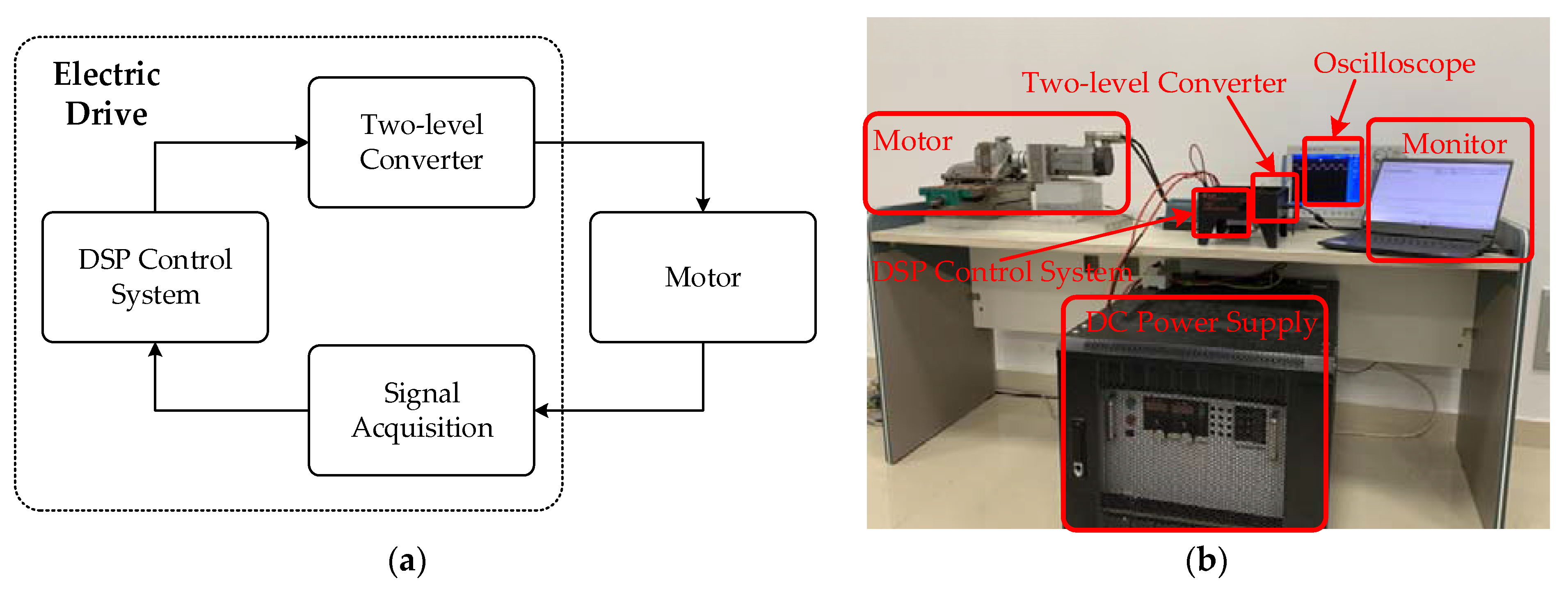
Following the principle of each overmodulation strategy, and using the single Fourier integral transform, the nth low-order harmonic components hn (=Vout_n/Vout_1) about the output voltage can be obtained, as shown in Figure 9.
Figure 9 shows the main low-order harmonic components of the output voltage, and it can be seen from this figure that when 0.866 < m ≤ 0.909, the fifth and seventh harmonic components of strategies A and C do not exceed 3%, and the fifth and seventh harmonic components of strategies B and D are much larger.

4. Experiment

In order to verify the above theory and analyze the practicality of each overmodulation strategy, a two-level converter test system was built, as shown in Figure 10. The experimental parameters are shown in Table 1.

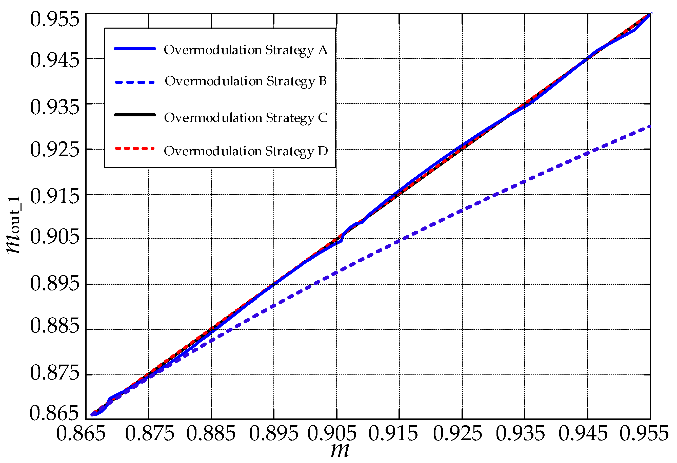
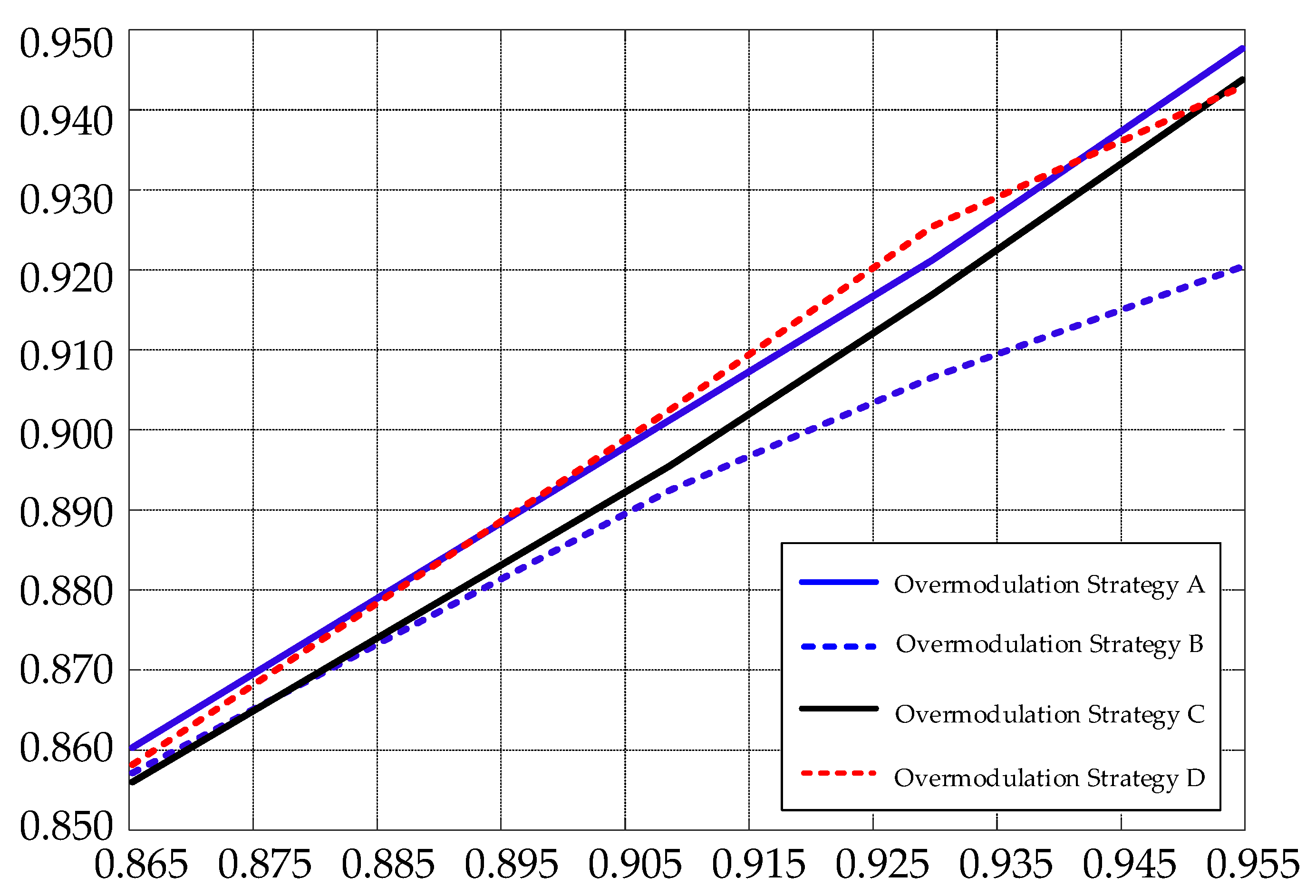
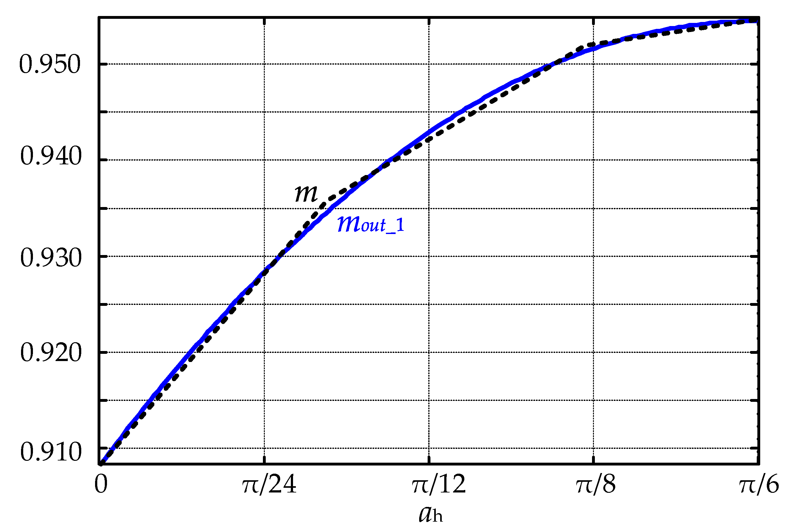
4.1. Verification and Analysis of VTR

As mentioned previously, after the linearization of overmodulation strategies A, C, and D, the fundamental VTR was basically consistent with the expected value, while strategy B was lower than the rest. The deviation increased with the increase in the modulation ratio. Compared with Figure 8, the results were basically consistent. Due to the existence of nonlinear factors such as switch tube voltage drop and dead band, there was a percentile deviation between the actual and the theoretical results, as shown in Figure 11 and Table 2. Obviously, the experimental data verified the correctness of the theoretical analysis.

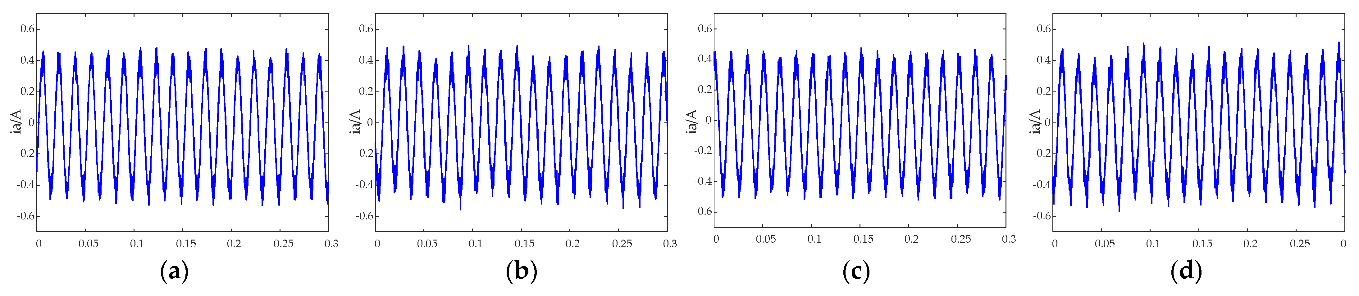
4.2. Verification and Analysis of Low-Order Harmonic Components

The experimental data were decomposed via fast Fourier transform, and the modulation ratio and content of harmonics could be obtained. When the fundamental voltage modulation ratio mout_1 = 0.909, the output phase voltage of each strategy is shown in Figure 12, and the Fourier transform results are shown in Figure 13. The results were consistent with those of the previous analysis. The harmonic components of strategies A and C were the same under this condition, the harmonic components of strategies B and D were relatively large, and the harmonic components of strategy D were the largest among the four strategies.
The experimental results of the fifth and seventh harmonic components are shown in Figure 14. When 0.866 < m ≤ 0.909, the fifth and seventh harmonic components of strategies A and C were less than 3%, and the fifth and seventh harmonic components of strategies B and D were far greater than those of strategies A and C. Compared with Figure 9, the results were basically consistent. In addition, the phase current waveform of the motor is shown in Figure 15. It is clear that the current harmonic components of strategies B and D also exceed those of strategies A and C. Therefore, the correctness of the theoretical analysis was verified through these experiments.

5. Characteristic Comparison of Space Vector Overmodulation Techniques

The space vector overmodulation strategies can be divided into single-mode and dual-mode space vector overmodulation strategies based on the analysis and comparison of their characteristics, as shown in Figure 16.
The single-mode overmodulation strategy directly regulates the magnitude and phase of the reference voltage vector, which is a kind of MMEPWM. In contrast, the dual-mode overmodulation strategy divides the overmodulation region into regions I and II, and the boundary VTR of the two regions is the maximum fundamental VTR obtained by only adjusting the magnitude of the reference voltage vector. In detail, the overmodulation region I only adjusts the magnitude of the reference voltage vector, which is a kind of MPEPWM; and the overmodulation region II simultaneously adjusts the magnitude and phase of the reference voltage vector to obtain a higher VTR, which is a kind of MMEPWM. Compared with the single-mode overmodulation, the output waveform of the dual-mode overmodulation strategy reduces the harmonic distortion.
The specific implementation of the space vector overmodulation strategy is divided into two methods: sub-trajectory and limit trajectory superposition.
In the sub-trajectory strategies, the output voltage vector adopts the lower bound trajectory vector of the overmodulation region when the angle θ between the reference output voltage vector and the adjacent effective voltage vector does not exceed the division angle. By contrast, when θ is equal to or larger than the division angle, the output voltage vector adopts the upper bound trajectory vector of the overmodulation region. The realization method of the sub-trajectory needs to establish a nonlinear mathematical relationship between the boundary angle and the fundamental magnitude of the output voltage by using the single Fourier integral transform. After that, approximate linearization is performed to obtain the specific value of the boundary angle α. Therefore, extensive data should be stored in the controller, offline and in advance, resulting in a considerable amount of system storage, which deteriorates algorithm accuracy and is adverse to engineering applications and portability. Moreover, this realization method also needs the symmetry of each sector.
The limit trajectory superposition is realized by the linear superimposed principle; this implementation method only needs to calculate the fundamental magnitude and harmonic components corresponding to the upper and lower limit trajectories. The result not only avoids a large number of Fourier integral or table-searching calculations but also obtains the linearized output voltage. Compared with the sub-trajectory method, the latter is more general and portable.

6. Conclusions

By analyzing and comparing the major modern space vector overmodulation technologies of two-level PWM converters, we divided the modern space vector overmodulation technologies into single-mode and dual-mode modulation strategies following their degree of regulation. On the grounds of the specific implementation method, the modern space vector overmodulation technology was divided into sub-trajectory and limit trajectory superposition strategies.
The dual-mode space vector overmodulation technique fully utilizes the two degrees of the two-level converter. Firstly, the output voltage with a small distortion rate is obtained by adjusting the magnitude of the reference voltage vector on the basis of improving the VTR. After that, the phase and magnitude of the reference voltage vector are simultaneously adjusted to obtain a higher VTR. Compared with the single-mode overmodulation technique, the dual-mode overmodulation technique can further reduce the output voltage THD under the same VTR.
The space vector overmodulation technique can be divided into several modes following the adjustable degree based on the converter topology. For example, the two-level converter can be adjusted by two degrees in the overmodulation region: the magnitude and phase of the reference output voltage. As a result, the two-level converter can be divided into single-mode and dual-mode overmodulation techniques. In contrast, the matrix converter can be adjusted by three degrees in the overmodulation region: the magnitude and phase of the output voltage vector and the phase of the input current. Therefore, the matrix converter can be divided into single-mode, dual-mode, and multi-mode overmodulation techniques.
The implementation method based on the limit trajectory superposition does not require symmetry in each sector and only needs to calculate the fundamental magnitude and harmonic components corresponding to the upper and lower limit trajectories to achieve its goal. Compared with the overmodulation strategy based on the sub-trajectory principle, it has the advantages of generality and portability, thus it can be transferred to converters of different topologies.

Author Contributions

Conceptualization, S.L.; methodology, S.L.; software, J.Z. (Jin Zhou); validation, J.Z. (Jin Zhou); formal analysis, S.L. and J.Z. (Jin Zhou); investigation, S.L.; resources, S.L.; data curation, J.Z. (Jin Zhou); writing—original draft preparation, S.L. and J.Z. (Jin Zhou); writing—review and editing, S.L., J.Z. (Jin Zhou), J.Z. (Jianing Zhang), and T.F.; visualization, S.L. and J.Z. (Jin Zhou); supervision, S.L. and X.Z.; project administration, S.L.; funding acquisition, S.L. and X.Z. All authors have read and agreed to the published version of the manuscript.

Funding

This research was funded by the National Natural Science Foundation of China under Grant (51907049), the Central Guidance on Local Science and Technology Development Fund of Hebei Province (226Z1805G), the Natural Science Foundation of Hebei Province (E2020202095), and the Tianjin Nature Science Foundation under Grant (20JCQNJC00370).

Institutional Review Board Statement

Not applicable.

Informed Consent Statement

Not applicable.

Data Availability Statement

Not applicable.

Conflicts of Interest

The authors declare no conflict of interest.

References

  1. Zou, N.; Yan, Y.; Shi, T.; Song, P. Wide Speed Range Operation Strategy of Indirect Matrix Converter–Surface Mounted Permanent Magnet Synchronous Motor Drive. Energies 2021, 14, 2277. [Google Scholar] [CrossRef]
  2. Liu, Q.; Hameyer, K. A Deep Field Weakening Control for the PMSM Applying a Modified Overmodulation Strategy. In Proceedings of the 8th IET International Conference on Power Electronics, Machines and Drives (PEMD 2016), Glasgow, UK, 10–21 April 2016; pp. 1–6. [Google Scholar]
  3. Park, D.-H.; Kim, M.; Lee, W.-J. Three-Phase and Single-Phase Motor Drive System with Single Three-Phase Two-Level Inverter for Independent Speed Control. J. Power Electron. 2022, 22, 40–49. [Google Scholar] [CrossRef]
  4. Fathy Abouzeid, A.; Guerrero, J.M.; Endemaño, A.; Muniategui, I.; Ortega, D.; Larrazabal, I.; Briz, F. Control Strategies for Induction Motors in Railway Traction Applications. Energies 2020, 13, 700. [Google Scholar] [CrossRef]
  5. Li, S.; Chen, W.; Yan, Y.; Shi, T.; Xia, C. A Multimode Space Vector Overmodulation Strategy for Ultrasparse Matrix Converter With Improved Fundamental Voltage Transfer Ratio. IEEE Trans. Power Electron. 2018, 33, 6782–6793. [Google Scholar] [CrossRef]
  6. Holtz, J.; Lotzkat, W.; Khambadkone, A.M. On Continuous Control of PWM Inverters in the Overmodulation Range Including the Six-Step Mode. IEEE Trans. Power Electron. 1993, 8, 546–553. [Google Scholar] [CrossRef]
  7. Nho, N.V.; Youn, M.J. Two-Mode Overmodulation in Two-Level Voltage Source Inverter Using Principle Control between Limit Trajectories. In Proceedings of the The Fifth International Conference on Power Electronics and Drive Systems. PEDS 2003, Singapore, 17–20 November 2003; Volume 2, pp. 1274–1279. [Google Scholar]
  8. Bolognani, S.; Zigliotto, M. Novel Digital Continuous Control of SVM Inverters in the Overmodulation Range. IEEE Trans. Ind. Appl. 1997, 33, 525–530. [Google Scholar] [CrossRef]
  9. Liwei, Z.; Xuhui, W.; Jun, L. A Novel Fundamental Voltage Amplitude Linear Output Control Strategy of SVPWM Inverter in the Overmodulation Region. In Proceedings of the 31st Annual Conference of IEEE Industrial Electronics Society. IECON 2005, Raleigh, NC, USA, 6–10 November 2005; p. 4. [Google Scholar]
  10. Hava, A.M.; Kerkman, R.J.; Lipo, T.A. Carrier-Based PWM-VSI Overmodulation Strategies: Analysis, Comparison, and Design. IEEE Trans. Power Electron. 1998, 13, 674–689. [Google Scholar] [CrossRef]
  11. Hava, A.M.; Sul, S.-K.; Kerkman, R.J.; Lipo, T.A. Dynamic Overmodulation Characteristics of Triangle Intersection PWM Methods. IEEE Trans. Ind. Appl. 1999, 35, 896–907. [Google Scholar] [CrossRef]
  12. Zhang, J.; Zhang, Y.; Deng, F.; Din, Z. Overmodulation Operation of Hybrid Modular Multilevel Converter with Reduced Energy Storage Requirement. IEEE J. Emerg. Sel. Top. Power Electron. 2022, 10, 2946–2958. [Google Scholar] [CrossRef]
  13. Zhang, Y.; Zhang, J.; Deng, F.; Din, Z. Voltage Balancing Control of Hybrid MMC under Over-Modulation Situations with Optimal Circulating Current Injection. Int. J. Electr. Power Energy Syst. 2022, 140, 108053. [Google Scholar] [CrossRef]
  14. Seok, J.-K.; Sul, S.-K. A New Overmodulation Strategy for Induction Motor Drive Using Space Vector PWM. In Proceedings of the Proceedings of 1995 IEEE Applied Power Electronics Conference and Exposition-APEC’95, Dallas, TX, USA, 5–9 March 1995; Volume 1, pp. 211–216. [Google Scholar]
  15. Seok, J.-K.; Kim, J.-S.; Sul, S.-K. Overmodulation Strategy for High-Performance Torque Control. IEEE Trans. Power Electron. 1998, 13, 786–792. [Google Scholar] [CrossRef]
  16. Li, L.; Wang, H.; Chen, X.; Bukhari, A.A.S.; Cao, W.; Chai, L.; Li, B. High Efficiency Solar Power Generation with Improved Discontinuous Pulse Width Modulation (DPWM) Overmodulation Algorithms. Energies 2019, 12, 1765. [Google Scholar] [CrossRef]
  17. Li, S.; Xia, C.; Yan, Y.; Shi, T. Space-Vector Overmodulation Strategy for Ultrasparse Matrix Converter Based on the Maximum Output Voltage Vector. IEEE Trans. Power Electron. 2017, 32, 5388–5397. [Google Scholar] [CrossRef]
  18. Lee, D.-C.; Lee, G.-M. A Novel Overmodulation Technique for Space-Vector PWM Inverters. IEEE Trans. Power Electron. 1998, 13, 1144–1151. [Google Scholar] [CrossRef]
  19. El Khatib, H.; Gaona, D.; Gerling, D.; Saur, M. Deadbeat Flux Vector Control with Continuous Transition from Linear to Overmodulation Including Six-Step Operation Considering the Voltage and Current Limits by Applying One Single Control Law. In Proceedings of the 2021 23rd European Conference on Power Electronics and Applications (EPE’21 ECCE Europe) Ghent, Belgium, 6–10 September 2021; pp. 1–10. [Google Scholar]
  20. Bennett, W.R. New Results in the Calculation of Modulation Products. Bell. Syst. Tech. J. 1933, 12, 228–243. [Google Scholar] [CrossRef]
  21. Bowes, S.R. New Sinusoidal Pulsewidth-Modulated Invertor. Proc. Inst. Electr. Eng. 1975, 122, 1279–1285. [Google Scholar] [CrossRef]
  22. Bowes, S.R.; Bird, B.M. Novel Approach to the Analysis and Synthesis of Modulation Processes in Power Convertors. Proc. Inst. Electr. Eng. 1975, 122, 507–513. [Google Scholar] [CrossRef]
  23. Boys, J.T.; Handley, P.G. Harmonic Analysis of Space Vector Modulated PWM Waveforms. Electr. Power Appl. IEE Proc. B 1990, 137, 197–204. [Google Scholar] [CrossRef]
  24. Takahashi, I.; Sekiguchi, T.; Miyairi, S. Control of PWM Inverter Output Wave with Reduced Low-Order Harmonic Components. Electr. Eng. Jpn. 1977, 97, 57–63. [Google Scholar] [CrossRef]
  25. Bowes, S.R.; Clements, R.R. Computer-Aided Design of PWM Inverter Systems. IEE Proc. B Electr. Power Appl. 1982, 129, 1. [Google Scholar] [CrossRef]
  26. Bresnahan, K.; Zelaya de la Parra, H.; Teodorescu, R.; Evans, P.D. Harmonic Analysis of SVM and Experimental Verification in a General Purpose Induction Motor Test Rig. In Proceedings of the 1994 Fifth International Conference on Power Electronics and Variable-Speed Drives, London, UK, 26–28 October 1994; pp. 352–356. [Google Scholar]
  27. Moynihan, J.F.; Egan, M.G.; Murphy, J. Theoretical Spectra of Space-Vector-Modulated Waveforms. Electr. Power Appl. IEE Proc. 1998, 145, 17–24. [Google Scholar] [CrossRef]
Figure 1. Vector diagram: (a) space vector modulation strategy of the VSI; (b) equivalent vector circles under different modulation ratios.
Energies 15 07086 g001
Figure 2. Dual-mode space vector overmodulation based on sub-trajectory: (a) mode I; (b) mode II.
Energies 15 07086 g002
Figure 3. Single-mode space vector overmodulation based on sub-trajectory.
Energies 15 07086 g003
Figure 4. Dual-mode space vector overmodulation based on limit trajectory superposition: (a) mode I; (b) mode II.
Energies 15 07086 g004
Figure 5. Single-mode space vector overmodulation based on limit trajectory superposition.
Energies 15 07086 g005
Figure 6. mout_1 and m related to ar.
Energies 15 07086 g006
Figure 7. mout_1 and m related to ah.
Energies 15 07086 g007
Figure 8. mout_1 associated with m.
Energies 15 07086 g008
Figure 9. Harmonic components: (a) 5th; (b) 7th.
Energies 15 07086 g009
Figure 10. Two-level converter test system: (a) system block diagram; (b) testing platform.
Energies 15 07086 g010
Figure 11. Experimental results of base-wave VTR for each strategy.
Energies 15 07086 g011
Figure 12. Experiment waveform of output phase voltage at m = 0.909: (a) strategy A; (b) strategy B; (c) strategy C; (d) strategy D.
Energies 15 07086 g012
Figure 13. Fourier transform results of output phase voltage harmonic at m = 0.909: (a) strategy A; (b) strategy B; (c) strategy C; (d) strategy D.
Energies 15 07086 g013aEnergies 15 07086 g013b
Figure 14. Experimental results of low-order harmonic components: (a) 5th; (b) 7th.
Energies 15 07086 g014
Figure 15. Experimental results of output phase current at m = 0.909: (a) strategy A; (b) strategy B; (c) strategy C; (d) strategy D.
Energies 15 07086 g015
Figure 16. Classification of space vector overmodulation technology.
Energies 15 07086 g016
Table 1. Parameters of experiment setup.
ParametersValue
DC bus voltage (Vdc)100 V
Carrier frequency10 kHz
Output fundamental frequency60 Hz
Table 2. Experimental results of fundamental modulation ratio output by each strategy.
Modulation RatioStrategy AStrategy BStrategy CStrategy D
0.86600.86120.85810.85700.8591
0.90000.89290.88260.89510.8940
0.90900.90120.89260.89560.9024
0.93000.92070.90640.91650.9248
0.95480.94650.91990.94270.9419
0.95480.94650.91990.94270.9419
Publisher’s Note: MDPI stays neutral with regard to jurisdictional claims in published maps and institutional affiliations.

