1. Introduction
Lithium-ion batteries have been widely used in the field of new energy automobiles, but long-term continuous and frequent fast charging will cause the temperature to rise sharply during the charging process, causing damage to the battery and increasing the risk of use. Therefore, achieving fast charging and effective thermal management on the basis of the safety of the battery has become a current research hotspot for scholars.
The most widely used charging method for lithium-ion batteries is the traditional constant current-constant voltage charging. Although it combines the advantages of constant current charging and constant voltage charging methods, it does not meet the current demand for safe and fast charging in the field of lithium-ion batteries. At present, the improvement and promotion of the optimized charging strategy for lithium-ion batteries mainly focus on three aspects: shortening the charging time, prolonging the battery life, and battery thermal management, and some progress has been made.
Existing battery optimization charging research is mainly divided into two categories: one is to explore more accurate lithium-ion battery models, such as equivalent circuit models or electrochemical models [
1]. Through the experiments and analysis of the charging and discharging process of lithium-ion batteries, its performance characteristics can be better understood, and appropriate charging strategies can be adopted in different charging stages. The other category is to establish objective functions for optimization goals, such as battery life, charging speed, and battery temperature rise, and then use artificial intelligence algorithms to assist in calculating the optimal charging current of lithium batteries. The main methods are the pulse charging method, the multi-stage constant current charging method, and so on.
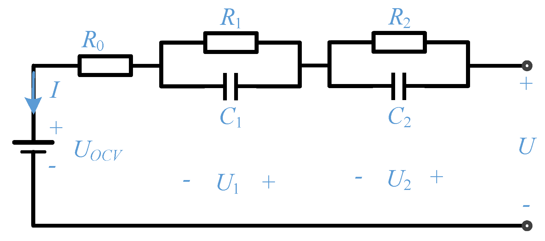
The equivalent circuit model can simulate the working process of the battery relatively accurately. For example, the most common battery internal resistance model has the fewest parameters and simple structure, but the simulation of the battery polarization phenomenon is not accurate enough; the first-order RC model (Thevenin equivalent circuit model) adds polarization resistance and polarization capacitance to realize the expression of the battery polarization response; the second-order RC model introduces the parallel concentration impedance on the basis of the first-order model, which can better describe the effect of concentration polarization on the battery. In addition, the partnership for a new generation of vehicle (PNGV) models adds tandem capacitance to describe the change of the battery open circuit voltage with the current time integral, which can more accurately describe the DC response characteristics of the battery. The model can simulate the influence of the charging and discharging current on the open-circuit voltage of the battery in the actual charging and discharging process through the battery capacitance and the ideal voltage source, and the superimposed voltage changes of the two are caused when the charging and discharging current changes. However, the accurate simulation of the battery system by the model also complicates the model structure and model parameters, which greatly increases the amount of computation.
Some scholars study the internal mechanism of the battery from the electrochemical point of view, analyze the internal working state of the battery, and avoid the damage to the battery caused by the polarization phenomenon and lithium precipitation during the charging and discharging process. The most commonly used model is the pseudo-two-dimensional mechanism model (P2D), which describes the chemical reactions of the solid and liquid phases inside the lithium-ion battery and has positive significance for exploring the optimal charging strategy to prolong the battery life. Liu, J. et al. [
2] established the second-order RC equivalent circuit model and P2D electrochemical model of lithium-ion batteries and calculated the maximum acceptable charging current curve for lithium-ion batteries to inhibit the precipitation of metal lithium. The curve was set as the safety boundary, and the multi-objective iterative optimization of the charging time, charging capacity, and charging loss in the charging process was carried out with the aid of the particle swarm intelligent optimization algorithm, and the intelligently optimized fast charging strategy was obtained.
The lumped parameter equivalent circuit thermal model is formed by coupling the battery thermal model and the circuit model. From the perspectives of electricity and heat, it completely describes the thermal dynamic characteristics of the battery during the charging and discharging process, such as heat generation and heat dissipation. Scholar Ma [
3] established a battery thermoelectric coupling model around the ternary material lithium-ion battery, proposed a charging optimization strategy suitable for batteries with different aging states, and used the particle swarm optimization algorithm of fuzzy reasoning to optimize the five-stage constant current charging process. Wu, T. et al. [
4] established a lithium-ion battery charging temperature rise model and proposed a multi-stage constant current fast charging method based on the genetic algorithm considering the charging temperature rise. The results show that this method not only reduces the overall charging temperature rise and lowers the temperature in the later stage of charging but also indirectly affects the life of lithium batteries. Ma, H. et al. [
5] proposed an optimal battery charging strategy based on a biogeography-based complex system optimization (BBO/Complex) algorithm. The lithium battery charging model was constructed as two subsystems, electric and thermal. The optimization objectives of the electronic system include battery charging time and energy loss, and the optimization objectives of the thermal subsystem include the internal temperature rise and surface temperature rise of the battery. The results show that this method can effectively achieve its two optimization goals.
Some scholars have proposed an electro-thermal-aging model, that is, the aging characteristics of the battery are also considered in the construction of the model. The battery capacity attenuation degree is calculated according to the parameters of the battery and is used as the output of the electric-thermal-aging model. Shi et al. [
6] proposed a multi-stage constant current charging strategy that can accurately characterize the physical and chemical reaction characteristics of the battery based on the electric-thermal-aging multi-parameter coupling model under the premise of balanced consideration of the aging loss and charging time of the lithium battery. Li et al. [
7] established a multi-state joint-estimation model for the coupling of electricity, heat, and aging of lithium-ion batteries based on the first-order RC equivalent circuit model, thermal network method and aging model. The multi-stage constant current charging strategy was compared with the traditional constant current-constant voltage strategy. Li, Y. et al. [
8] combined the electro-thermal-aging coupling single cell model with the battery pack cooling model and the battery pack balance management model into a battery pack model. Based on this model, a multi-objective consideration of charging time, aging, and energy loss was proposed. The optimal charging strategy was optimized by using the genetic algorithm to optimize the adaptive multi-phase constant current and constant voltage charging strategy.
Some scholars use artificial intelligence algorithms to assist in calculating the optimal charging current of lithium batteries so that they can be optimized in terms of battery life, charging speed, and battery temperature rise. The pulse charging method proposed by some scholars was applied and developed to a certain extent because it can add intermittent time or negative pulse phase to eliminate battery polarization, reduce gas evolution and shorten charging time. However, this method has high requirements on the controller and low energy conversion. In order to improve the charging efficiency, Boadu, J.A. et al. [
9] used the Taguchi orthogonal array method to optimize the pulse charging parameters and found that the optimal charging frequency is the frequency that minimizes the AC impedance of the battery. Compared with CC-CV, the average current in the CC phase is the same, the charging time is significantly shorter, and the efficiency is higher, but the temperature rise is higher. Song, M. et al. [
10] established a side reaction model, a lithium plating model, and a stripping model and incorporated them into a reduced order electrochemical model (ROM) with extended Kalman filter and designed a negative pulse with ROM estimation. The fast-charging method with negative pulse (FCNP) combines the limitations of anode potential, side reaction rate, and cut-off voltage. The results show that the charging time to reach 80% SOC is comparable to that of 3C CC-CV, while the capacity loss of FCNP is comparable to that of 2C CC-CV.
Another common optimized charging method is multi-stage constant current charging, which often uses intelligent algorithms such as the particle swarm algorithm and genetic algorithm. According to the listed objective function composed of time, temperature, aging degree, and other parameters, the optimal current of each stage is solved by continuously solving the extreme value within the allowable range of the parameters. According to the characteristics of lithium-ion batteries, lithium batteries usually go through a pre-charging process with a small current in the initial stage of charging and then enter the formal high-current charging stage. Due to the high energy ratio of lithium batteries, if they enter the fast-charging mode directly, it may cause damage to the battery, affect the service life, and possibly bring safety hazards. In the initial stage of high-current charging, the maximum allowable charging current is large, and a higher charging rate can be used. With the increase in SOC, the maximum allowable charging current will gradually decrease so the corresponding charging rate should also gradually decrease. Hu, X. et al. [
11] used the particle swarm optimization algorithm to obtain the optimal charging current curve for the two different charging objectives of charging time and battery capacity decay. Compared with the 0.5C CC-CV charging strategy, the proposed multi-stage constant-current charging strategy can significantly reduce the charging time, and the capacity degradation is almost negligible. Min, H. et al. [
12] proposed an optimal charging strategy for Li-ion batteries based on the voltage-based multistage constant current (VMCC) charging strategy using a multi-objective particle swarm optimization (MOPSO) algorithm and analyzed the effects of different charging target numbers, charging cut-off voltages, and weighting factors. The experimental results show that the charging performance of the proposed charging strategy can be improved by more than 80% compared with the traditional charging strategy. Patnaik, L. et al. [
13] proposed a charging technology based on constant temperature and constant voltage (CT-CV) that regards battery temperature as a key degradation indicator and uses a proportional-integral-derivative (PID) controller to control the charging current to dynamically adjust according to battery temperature. The results show that the total temperature rise of the proposed method is 20% lower than that of the CC-CV charging method when the total charging time is the same as that of the constant current-constant voltage charging method. Wu, X. et al. [
14] proposed a multi-stage charging method with charging time and energy loss as optimization objectives. Based on the dynamic model of a first-order circuit, the objective function of the optimization problem was regarded as the weighted sum of charging time and energy loss, and the charging current of the objective function was calculated using a dynamic programming algorithm (DP). The simulation and experimental results show that compared with the CC-CV charging method, the proposed charging method can effectively reduce the charging time and energy loss under the premise of less influence on the battery capacity attenuation. Wu, T.Z. et al. [
15] proposed a multi-stage constant current charging method suitable for lithium-ion batteries, using fuzzy logic to deduce the optimal adjustment rules for the weighting factors of multi-objective functions, and obtained the fitness of the objective function by using the improved whale optimization algorithm (WOA) to search for the segmented optimal current. The experimental verification shows that this strategy has the advantages of shortening the charging time and reducing the energy loss. Chen, G.J. et al. [
16] proposed a gray wolf optimization method to find the optimal charging mode with five-stage constant current considering both charging time and charging loss. The results show that the proposed charging method is comparable to the optimization method that only considers charging time. The maximum temperature rise, average temperature rise, and charging efficiency increased by 12.54%, 5.74%, and 0.21%, respectively. Liu, K. et al. [
17] based on an ensemble multi-objective biogeography-based optimization (EM-BBO) approach to simultaneously consider battery health, charging time, and energy conversion efficiency; imposed constraints on current, voltage, state of charge, and temperature; and optimized two charging modes: CC-CV and multi-stage constant current-constant voltage (MCC-CV). The results show that the proposed strategy can effectively provide feasible health-conscious charging and achieve an ideal trade-off between charging speed and energy conversion efficiency under different demand priorities.
In addition to applying intelligent algorithms to optimize the charging time, temperature rise, and energy loss of lithium-ion batteries, some scholars use the Taguchi method to optimize their charging mode. Jiang, L. et al. [
18] analyzed the charging capacity, efficiency, and time as quality functions and used the Taguchi method to find the optimal charging mode of the five-stage constant current charging strategy. Compared with the CC-CV method, the obtained charging mode improves the charging efficiency by 0.6–0.9% and reduces the temperature of the battery with a temperature rise of approximately 2 °C. Compared with the charging mode obtained by optimizing the charging time and capacity, the charging efficiency obtained in this paper was increased by 2.8%, the temperature rise was reduced by 9.3 °C, and the charging capacity was basically the same. Wang, S.C. et al. [
19] proposed a fuzzy Taguchi-based method (FBTM) to systematically adjust the charging rate of the multi-level charging current and obtained the adopted multi-level constant current optimal fast charging mode. The results show that compared with the traditional CC-CV method, the charging time of this scheme was shortened by more than 81%, the battery life was increased by more than 30%, and the charging efficiency was improved by more than 0.5%.
In addition, the excessive polarization voltage during the charging process may lead to gas evolution, which is prone to danger. Therefore, some scholars optimize the charging strategy from the perspective of polarization voltage control. Zhang, C. et al. [
20] proposed an optimization strategy for the charging time and temperature rise of lithium-ion batteries based on polarization voltage. An enhanced thermal behavior model was introduced to improve the solution accuracy under charging current. Additionally, the genetic algorithm (GA) was used to search for the most optimal charging current trajectory. Compared with 1/3C CC-CV charging, the charging time of the optimized charging protocol was reduced by 50%, and the temperature rise was almost the same. Aging experiments show that the proposed charging method has similar capacity retention to 0.5C CC-CV charging after 700 cycles, achieving a good balance between charging speed and lifetime. Chen, D.H. et al. [
21] proposed a three-stage optimization method for CC-CV charging, combined with the battery capacity decay process to correct the three-stage optimization method, using polarization voltage and open circuit voltage to correct the constant current and constant voltage process. The control object made the current and voltage change in real time with the actual state of charge of the battery. The comparative analysis of four groups of experiments with different charging methods shows that the three-stage optimization method can increase the charging efficiency to 94.25%, and the capacity attenuation value of the lithium battery decreases by 45% compared with that before the optimization.
To sum up, compared with traditional charging methods, these methods reduce the charging time and charging temperature rise to a certain extent and realize the fast charging of lithium-ion batteries on the basis of ensuring safety and reliability. Among them, the multi-stage constant current charging method can flexibly select a variety of artificial intelligence optimization methods and conveniently select the objective function composed of battery time, temperature, SOC, and other parameters. In addition, the maximum allowable charging current of the lithium-ion battery is larger in the initial stage of charging after pre-charging, a higher charging rate can be used to reduce the charging time, and the constant current charging method is less difficult to control the test equipment than in the constant voltage charging, which is convenient for large-scale engineering applications. In view of this, this paper adopts the multi-stage constant current charging method to optimize the charging time and charging temperature rise. First, the electric-thermal coupling model of the lithium-ion battery was established, and the parameters of the second-order RC equivalent circuit model were identified through the hybrid pulse power characterization (HPPC) experiment. Second, the multi-stage charging strategy of lithium-ion battery was optimized based on the particle swarm algorithm, and finally, the advantages of the proposed optimized charging strategy were verified by experimental comparison.
3. Lithium-Ion Battery Parameter Identification
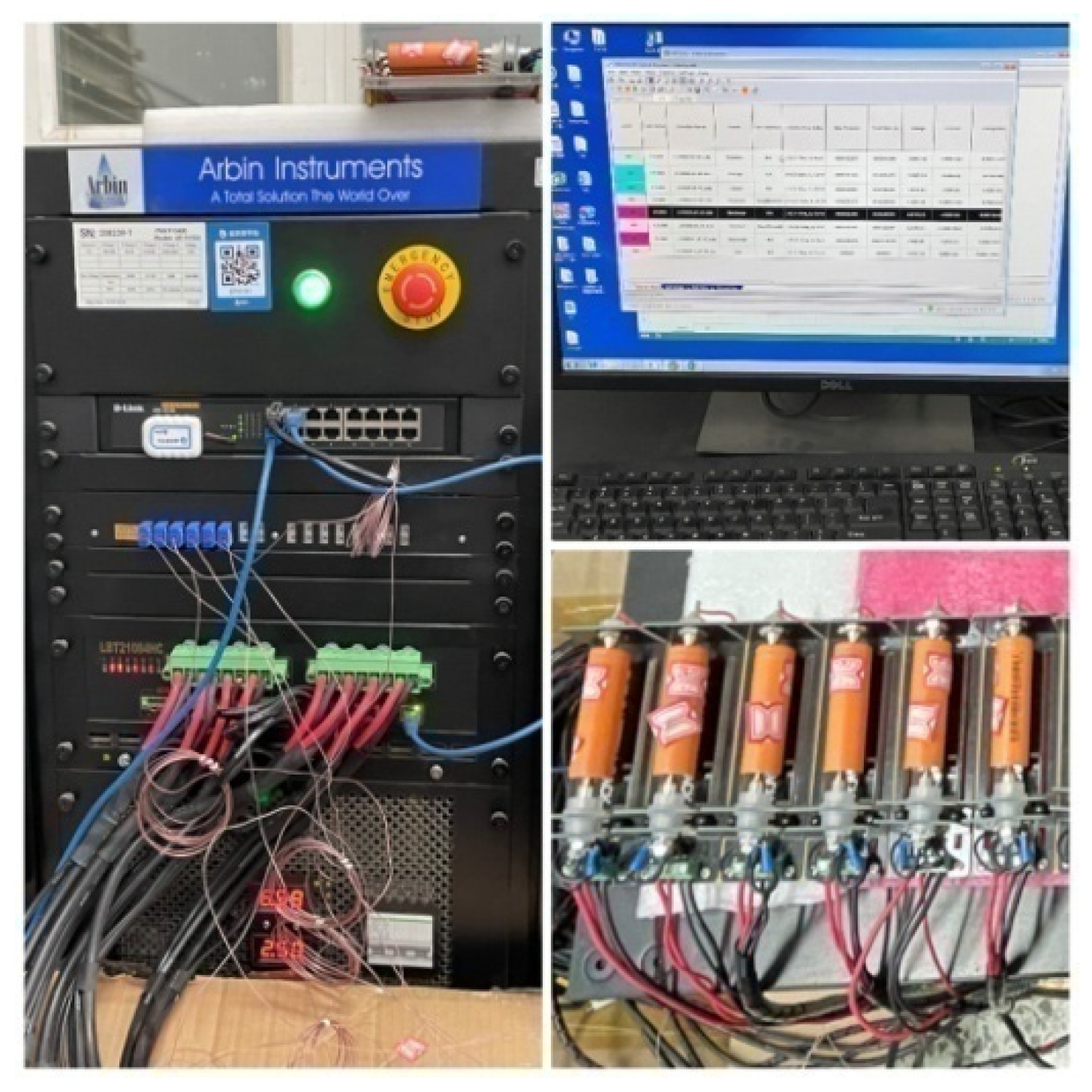
After establishing the electric-thermal coupling model of the lithium-ion battery, according to the “FreedomCAR Hybrid Electric Vehicle Battery Testing Manual”, the hybrid pulse power characteristic (HPPC) test was carried out to identify the battery parameters of the NCR18650B ternary lithium-ion battery, and a charging experiment was designed to verify the reliability of the model. The experimental equipment used was the Arbin BT-ML-30V/10A battery tester, as shown in
Figure 2. The main purpose of the charging experiment was to compare the actual battery terminal voltage with the model output voltage, as well as the actual battery temperature and the model output battery temperature, to verify the reliability of the model.
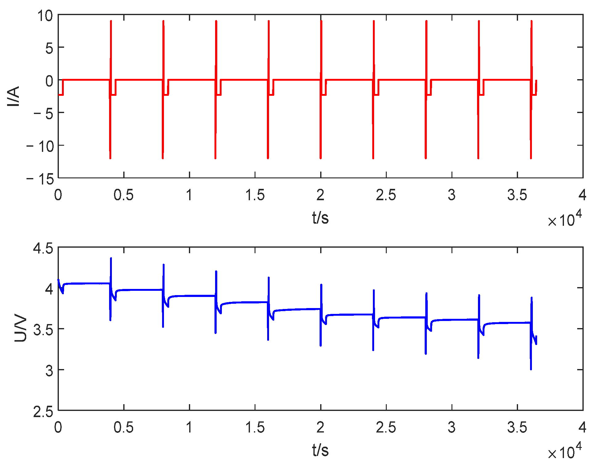
In this paper, the HPPC test experiment shown in
Figure 3 was used to identify the six parameters of ohmic internal resistance
, polarization resistance
and
, polarization capacitance
and
, and open circuit voltage
in the second-order RC equivalent circuit model. The HPPC test was composed of the repeated charge and discharge pulses. A 1C constant current discharge step was performed after a charge-discharge pulse was performed, and the capacity released during the pulse process was 10% DOD in total. Additionally, the C discharge was followed by a 1 h rest to allow the battery to return to electrochemical and thermal equilibrium before proceeding to the next cycle.
The least squares method is the simplest and most commonly used method in parameter identification methods. It finds out a set of parameter values by minimizing the square sum of the error and finding the best function matching for the data so that the voltage and SOC output by the battery model are consistent with the battery model. The real voltage and SOC are as close as possible to evaluate the actual state of the battery.
Since there is a corresponding relationship between the open circuit voltage of the battery and the state of charge of the battery, the open circuit voltage values at different SOCs can be sampled after the battery is sufficiently static so as to obtain the SOC- curve to establish the functional relationship between the two parameters.
At the beginning and end of charging and discharging of the battery, the ohmic internal resistance of the battery will cause a step change in the terminal voltage of the battery. Therefore, the ohmic internal resistance of the battery under different SOC states can be calculated from the ratio of the sudden change of voltage and current during the charging and discharging process. According to Ohm’s law, the ohmic internal resistance of the battery in a certain SOC state during the charging process and the discharging process can be expressed by Equation (29):
In addition, the polarization capacitor in the battery model will store electric field energy during the charging process and form a discharging loop with the parallel resistor during the static process. Therefore, the polarization resistance and polarization capacitance of the two groups in parallel need to be obtained according to the change law of the voltage curve in the charging and discharging of HPPC and the static phase.
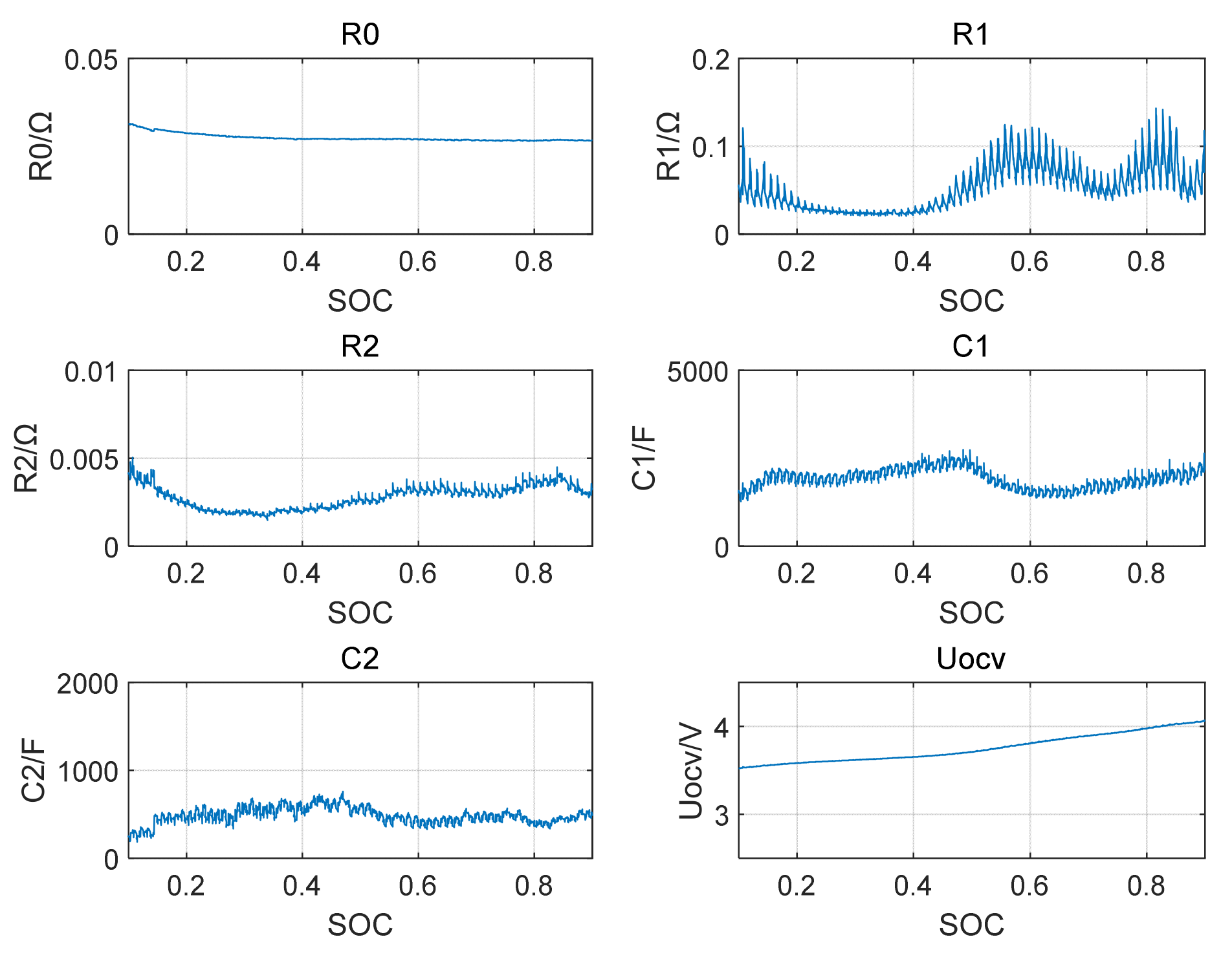
Since the parameters are different in different SOC states, it is necessary to repeat the parameter identification steps at different SOC points, and the identification results of each parameter in the second-order RC equivalent circuit model were obtained as shown in
Figure 4 below. The obtained results were fitted to function curves of SOC and various parameters in the circuit model and then applied to the lithium-ion battery model.
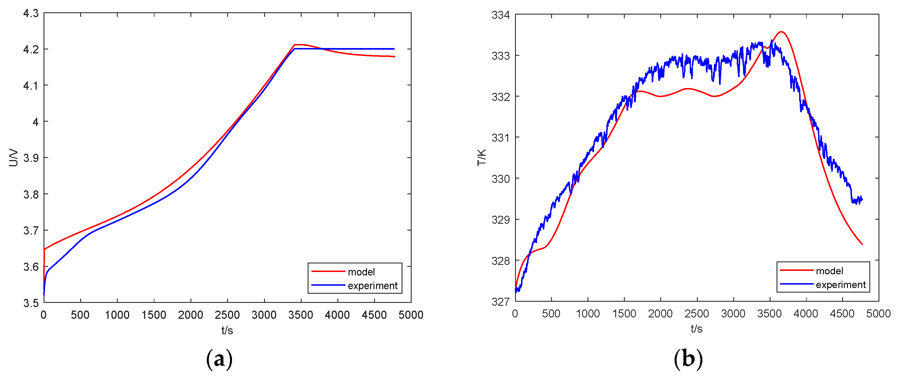
After the model parameter identification results were obtained, the battery was charged with a CC-CV charging method with a current of 2.4 A, and the simulation results of voltage and temperature were compared with the actual experimental results, which verifies the rationality of the electric-thermal coupling model established in
Section 2.2 of this paper.
Figure 5 shows the comparison of the terminal voltage and temperature curves between the model simulation and the experimental measurement.
4. Optimized Charging Strategy Based on Particle Swarm Algorithm
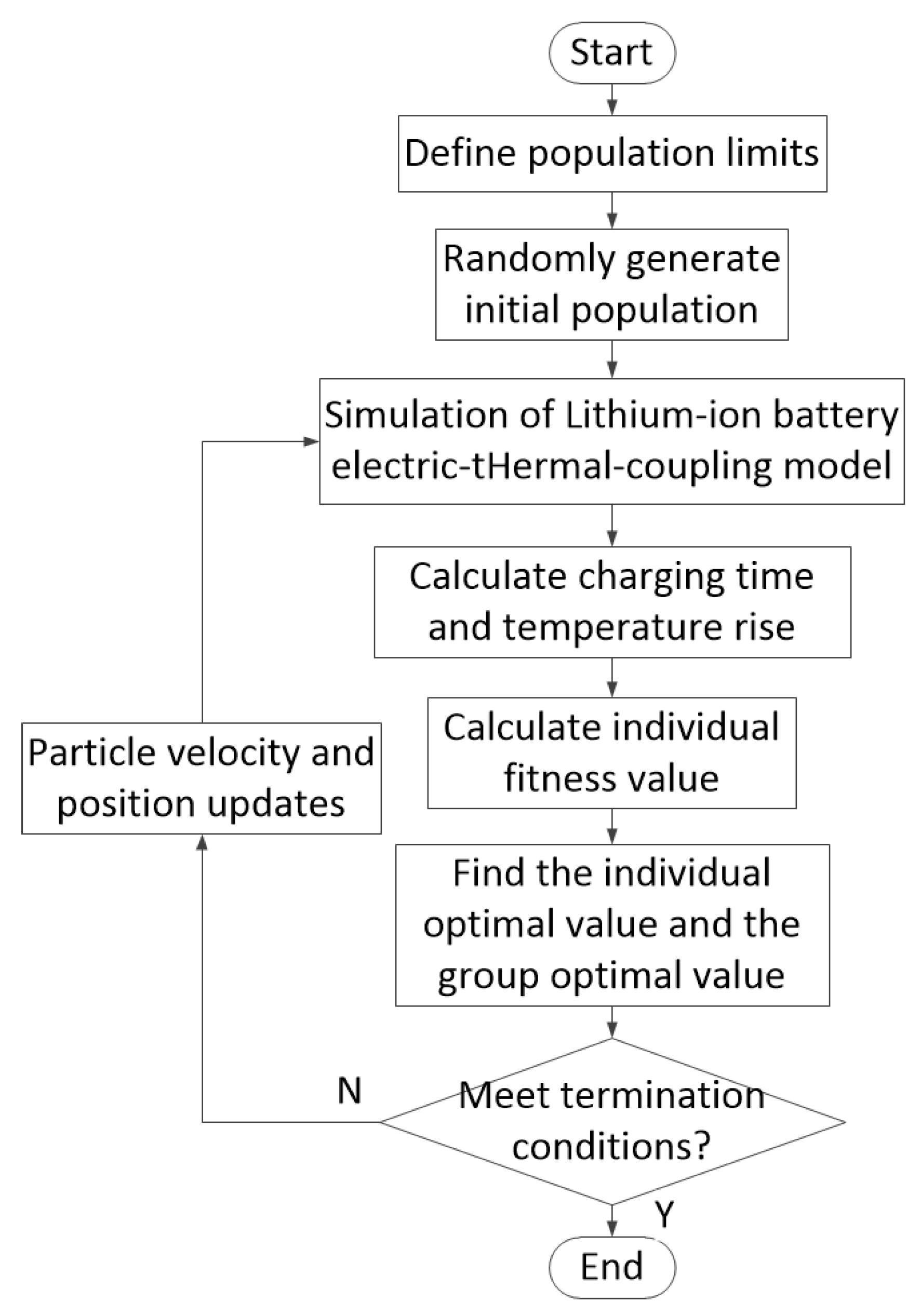
After establishing the electric-thermal coupling model, this paper used particle swarm optimization to optimize the charging current based on the established model. The flow chart of the particle swarm algorithm used in this paper is shown in
Figure 6 below:
The initial population was 100 groups of initial current values randomly generated according to the maximum current value 1C and the minimum current value 0.05C allowed for battery charging. Since the charging method used in this paper is multi-stage constant current charging, the capacity charged into the battery in each stage is the same, so the specific SOC needs to be calculated according to the number of segments. Therefore, the battery capacity that should be charged in each stage can be calculated according to the number of segments, and the corresponding charging time can be calculated from the battery capacity value obtained from the previous capacity test experiment with the charging reaching the specified SOC as the segment condition. Then, the obtained time series and current series are correspondingly input into the established electric-thermal coupling model, and the terminal voltage and temperature output according to this charging rule are obtained. The basic idea of particle swarm optimization is inspired by the research results of modeling and simulation of bird flock behavior. The particle velocity is the change of the current, and the position update is the magnitude of the new current is calculated through this change, and this new set of current values is brought into the charging process. The individual optimal value and the group optimal value in the iterative process are the minimum values calculated by the objective function in the individual and global iterations, respectively. The iteration stops when it is less than the minimum value of the fitness function or exceeds the maximum number of iterations. In this paper, reducing the charging time and reducing the temperature rise during the charging process are used as the optimization goals of lithium-ion battery charging, and the fitness function is established:
among them, α and β are the weight values of charging time and charging temperature rise and satisfy
,
and
are the corresponding charging time and charging temperature rise when charging with a maximum charging current of 1C,
and
are the corresponding charging time and charging temperature rise when charging with a minimum charging current of 0.05C.The charging current in each stage of this paper comprehensively considers the charging time and charging temperature rise and adopts the same weight value of 0.5.
First, the corresponding charging time and charging temperature rise were obtained according to the initialized 100 sets of the charging current simulation, and then the fitness function value was calculated, and the minimum value was recorded after comparing the 100 fitness function values. Then, we iteratively updated the particle position by the updated particle velocity, that is, the defined current value. In each iteration of the iterative process, the value of the fitness function was calculated once, and the obtained fitness function value was taken as its minimum value. The above steps were repeated iteratively until the minimum limit of the fitness function or the maximum number of iterations was reached. We recorded the minimum value at this time and the corresponding charging current value, and the obtained set of charging currents was the optimal value of the current multi-stage charging current.
Through the co-simulation of MATLAB and SIMULINK, the charging current and fitness function value of each stage of the optimal charging curve were obtained.
At present, there is no unified regulation and optimization method for the segmentation method of multi-stage constant current charging. This paper adopts three common segmentation methods: three-stage, four-stage, and five-stage. We carried out the simulation and compared the simulation results to obtain the optimal charging strategy. The maximum number of iterations set in the three-stage constant-current charging simulation process was 20, 30, and 50, respectively, and multiple tests were carried out, and the same iteration results were finally obtained.
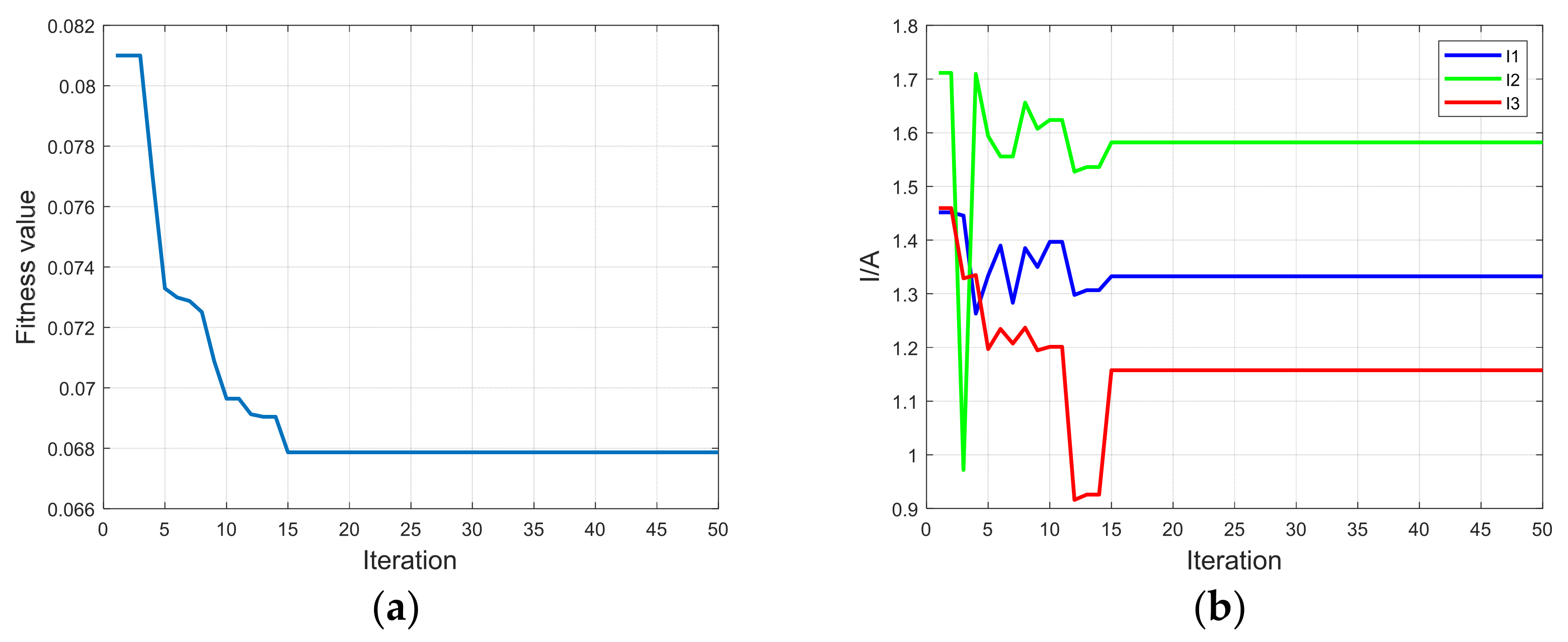
Table 1 shows the simulation results of 50 iterations of the three-stage constant current charging strategy:
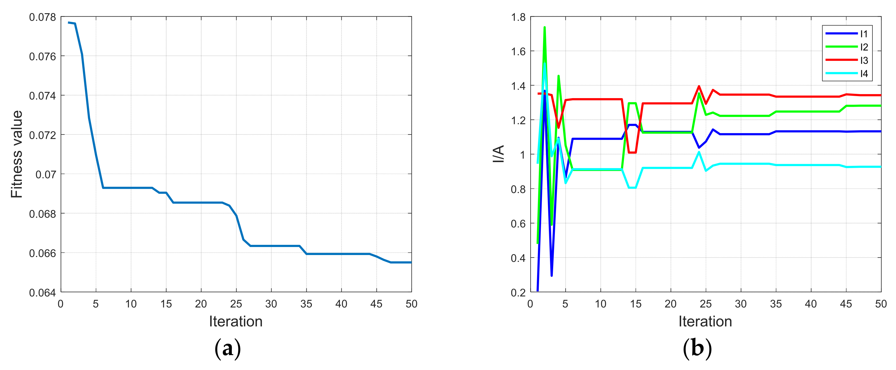
Figure 7 below shows the current optimization curve and fitness function optimization curve of each stage in the three-stage constant current charging simulation process.
Table 2 above shows the simulation results of the four-stage constant current charging strategy, and
Figure 8 below shows the current optimization curve and fitness function optimization curve of each stage in the simulation process of the four-stage constant current charging.
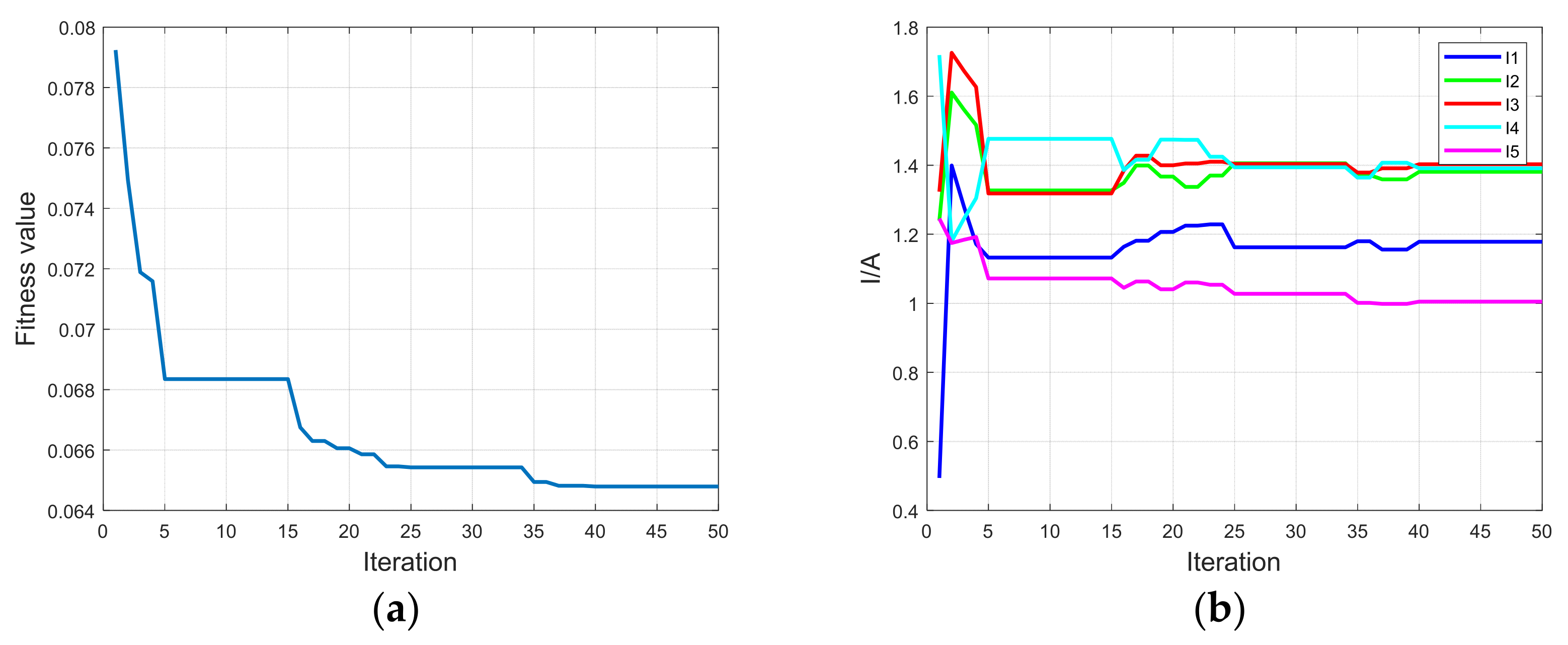
The simulation results of the five-stage constant current charging strategy are shown in
Table 3 above, and the current optimization curve and fitness function optimization curve of each stage in the simulation process of the five-stage constant current charging are shown in
Figure 9 below.
The simulation results show that with the increase in the number of iterations, the overall trend of the fitness function curve gradually decreases, which is in line with the expectation of the optimized charging strategy for less charging time and less temperature rise during the charging process. As shown in
Figure 6,
Figure 7 and
Figure 8, the fitness function value of the three-stage constant current charging became stable after the 15th iteration, while the four-stage and five-stage simulations required 47 and 37 times, respectively, to obtain the optimal fitness function value. In the simulation process, this paper set the maximum number of iterations as 20, 30, and 50 iterations for multiple simulations, and finally determined 50 as the maximum number of iterations in the simulation. The final fitness function value decreased with the increase in the number of segments, indicating that the five-stage constant current charging had better fitness than the three-stage constant current charging and the four-stage constant current charging. It can better meet the needs of reducing charging time and reducing charging temperature rise. However, at the same time, compared with the four-stage constant current charging and the five-stage constant current charging, the three-stage constant current charging has fewer subsections, and the control strategy is simpler and easier to operate.
5. Experimental Verification and Analysis
The NCR18650B ternary lithium-ion battery was selected as the experimental object. The capacity test of the battery was carried out first, and the actual capacity of the battery was obtained as 2549 mAh. The maximum charging current in the experiment was set to 1C, and the minimum charging current was 0.05C. According to the optimized charging strategy proposed above, charging experiments were carried out, respectively. In practical applications, 1C CC-CV charging was used to achieve fast charging, but the temperature rise during the charging process was too great, which would easily damage the battery life. Additionally, the charging time of the 0.2C CC-CV charging method specified by the national standard is too long to meet the needs of fast charging in practical applications. Therefore, this paper selects the 0.5C CC-CV charging method for comparison, which has more practical meaning in charging time and charging temperature rise.
Figure 10,
Figure 11,
Figure 12 and
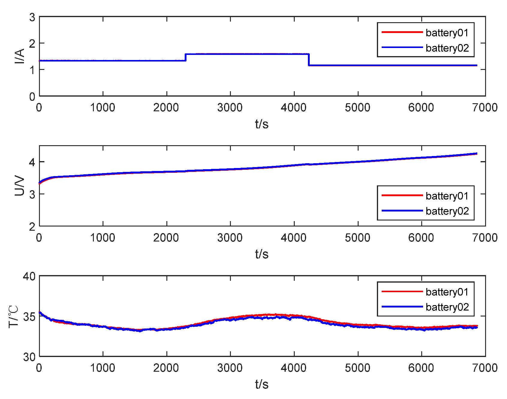
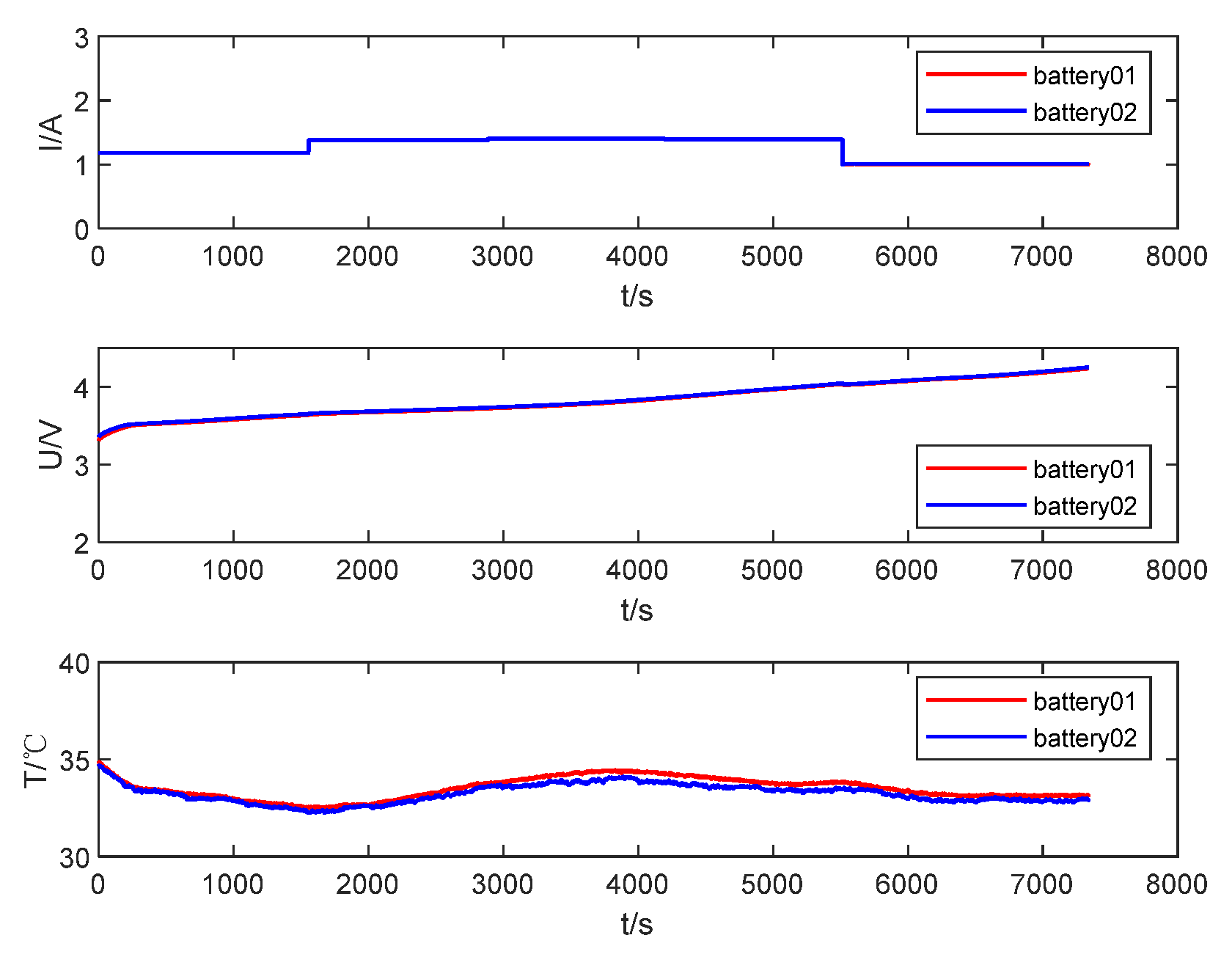
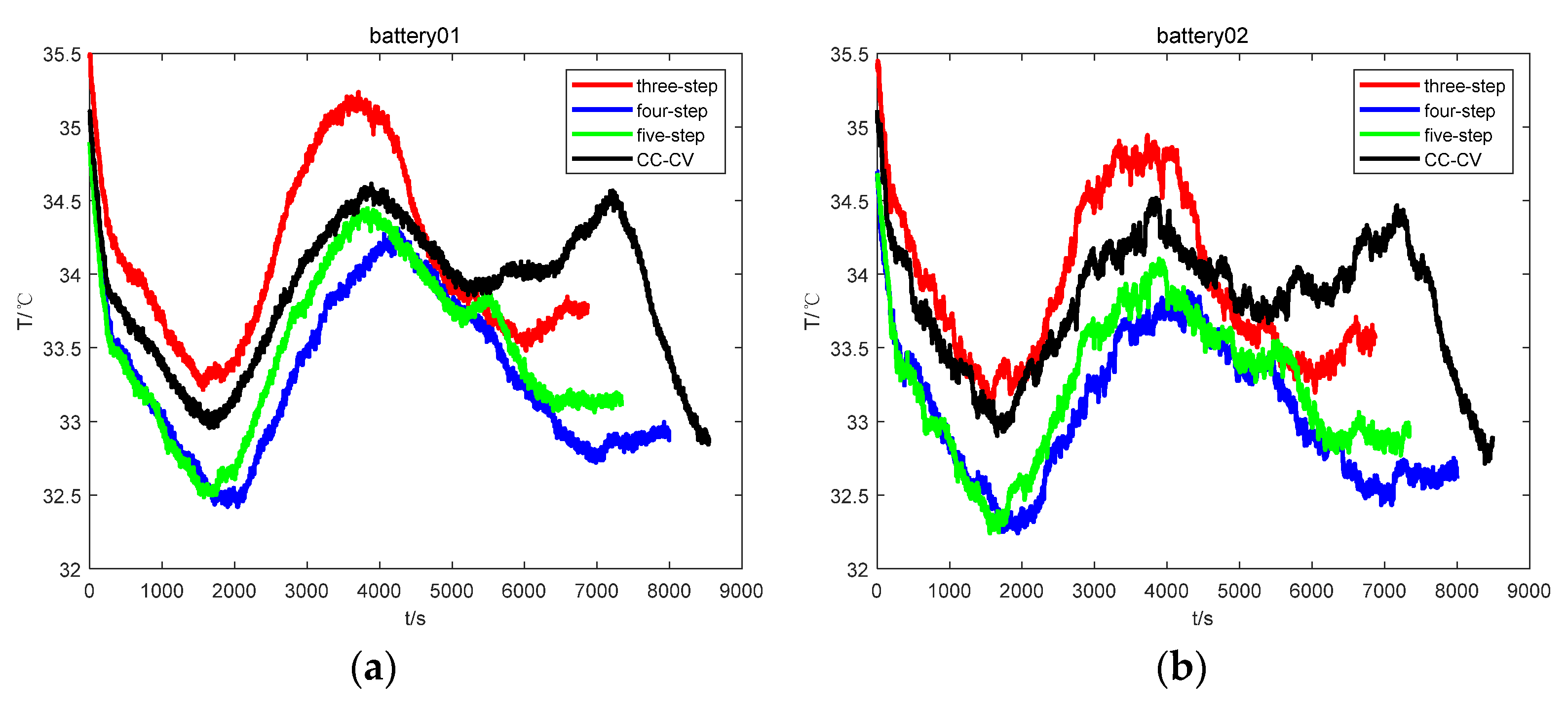
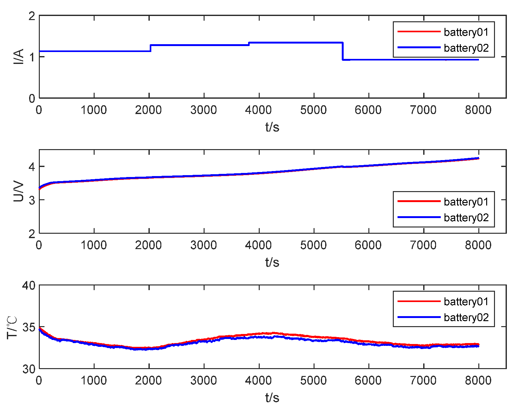
Figure 13 below shows the current, voltage, and temperature curves of three-stage, four-stage, and five-stage constant current charging and 0.5C CC-CV charging using two lithium-ion batteries of the same model and batch, respectively.
Through the comparison of the above figure, it can be found that with the increase in charging time, the battery voltage gradually increased to approximately 4.25 V, and the battery temperature first decreased and then increased from 35 °C. The reason the temperature decreased during the initial stage of charging was that the time was not long enough to ensure that the internal chemical reaction of the battery had reached a relatively stable state. The voltage and temperature curves of the three optimized charging methods proposed are generally consistent. The three-stage constant current charging took the shortest time, and the actual battery capacity was reached after 6870 s. The four-stage constant current charging took the longest, and it took a total of 7998 s to fully charge. Additionally, the five-stage constant current charging took a total of 7339 s. However, correspondingly, the temperature rise of the three-stage constant current charging was the most obvious, and the difference between the highest temperature and the lowest temperature of the two battery samples during the charging process was nearly 2 °C.
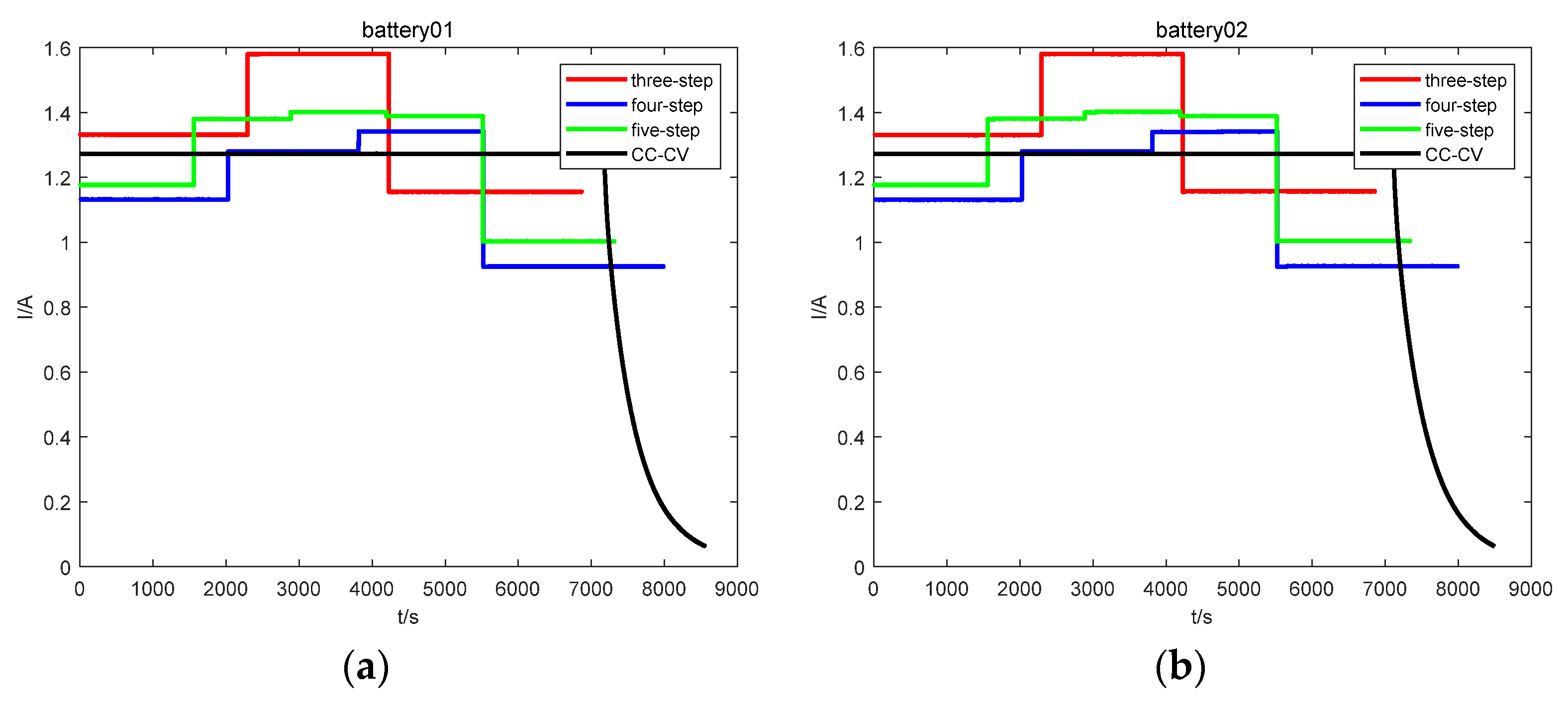
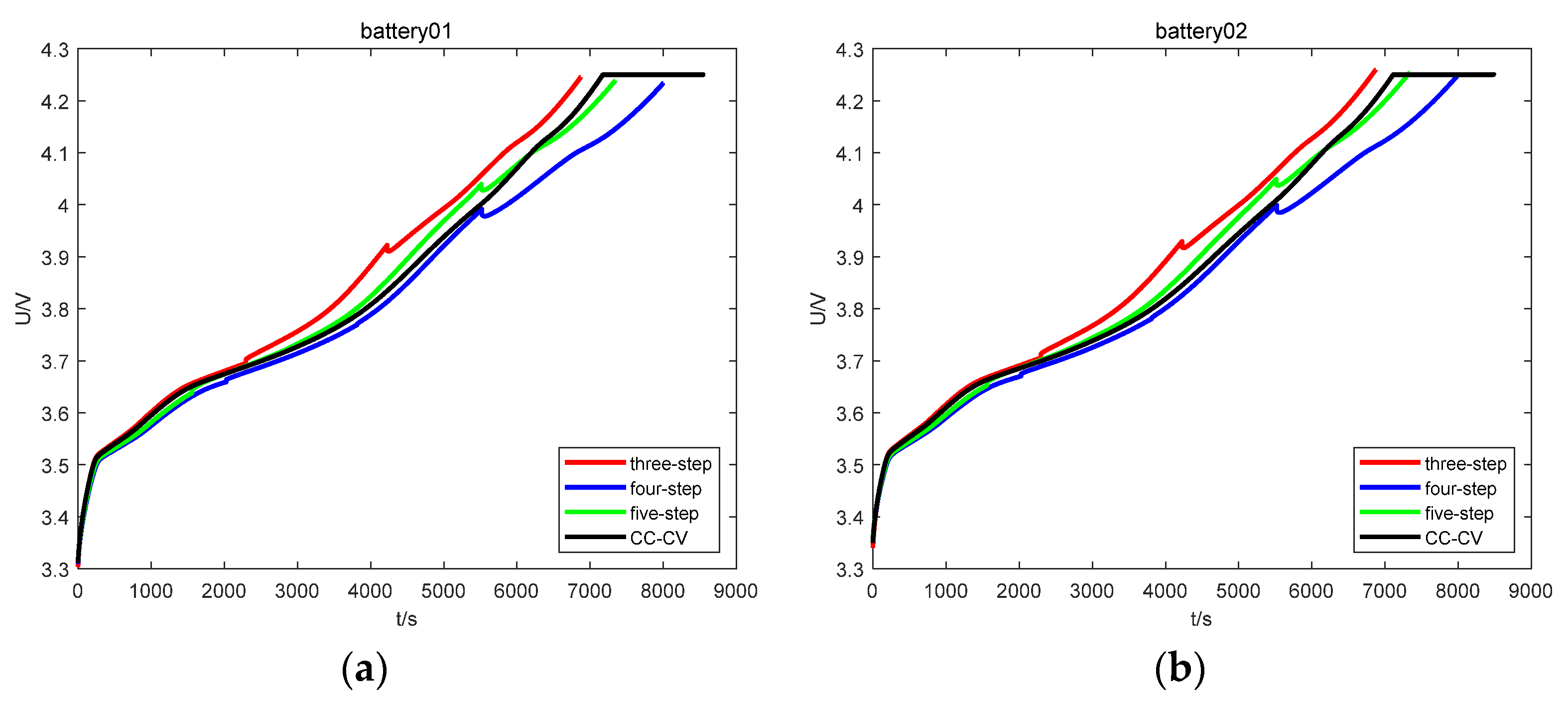
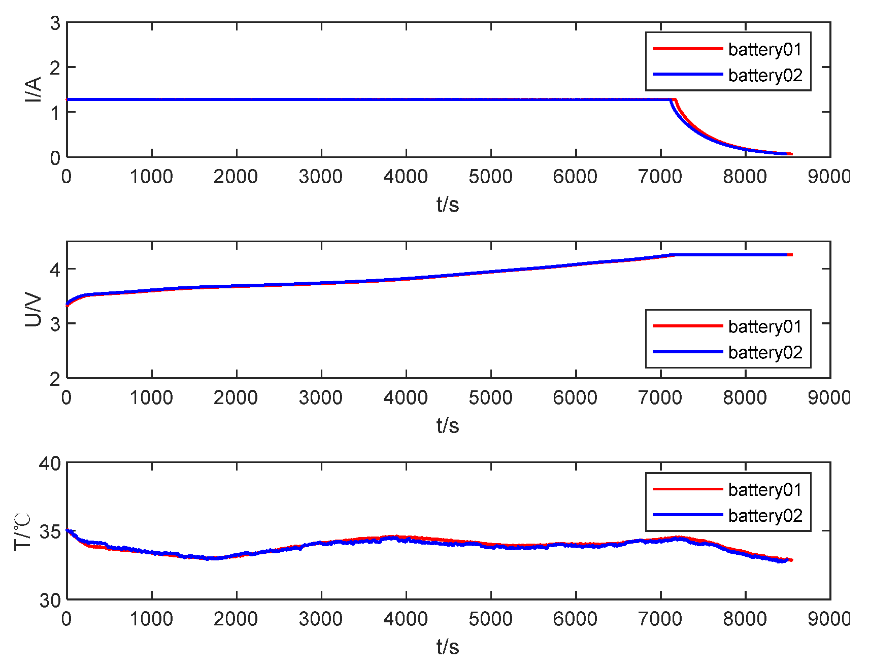
Figure 14,
Figure 15 and
Figure 16 above compare the current, voltage, and temperature curves during the charging process between the optimized charging strategy and the 0.5C CC-CV charging strategy of the two battery samples. The time required for the 0.5C CC-CV charging strategy of the two battery samples was 8551 s and 8490 s, respectively, and the four-stage optimized charging strategy with the longest time had an average time reduction of 6.13% compared with the 0.5C CC-CV charging strategy. It can be found from
Figure 16 that the highest temperatures during the charging process with 0.5C CC-CV charging reached 34.61 °C and 34.52 °C, which were 1.65 °C and 1.62 °C higher than the lowest temperatures of 32.96 °C and 32.9 °C, respectively. The proposed five-stage constant current charging method not only had an average maximum temperature of 34.28 °C lower than the maximum temperature in 0.5C CC-CV charging but also reduced the charging time by an average of 13.87%. Therefore, the five-stage constant current charging strategy proposed in this paper has obvious advantages in shortening the charging time and reducing the temperature rise.


