Article

Performance Analysis of Ultra-Scale Downwind Wind Turbine Based on Rotor Cone Angle Control

1
Research Center for Renewable Energy Generation Engineering of Ministry of Education, Hohai University, Nanjing 211100, China
2
Department of Mechanical and Construction Engineering, Northumbria University, Newcastle upon Tyne NE1 8ST, UK
3
China State Shipbuilding Corporation Haizhuang Windpower Co., Ltd., Chongqing 401123, China
4
School of Engineering, Newcastle University, Newcastle upon Tyne NE1 7RU, UK
5
Structural Engineering Research Center of Jiangsu Province Wind Turbine, Hohai University, Nanjing 211100, China
*
Author to whom correspondence should be addressed.
Energies 2022, 15(18), 6830; https://doi.org/10.3390/en15186830
Submission received: 5 August 2022 / Revised: 11 September 2022 / Accepted: 15 September 2022 / Published: 18 September 2022
(This article belongs to the Special Issue Theoretical and Technical Challenges in Offshore Wind Power)

Abstract

:
The theoretical feasibility of the power output strategy based on rotor cone angle control for ultra-scale downwind wind turbines is studied in this paper via the Open FAST simulation platform. The performance of five cases, namely UW, DW, DWC, DW6, and DW6IC, which have different rotor parameters or control strategies compared with the reference DTU 10 MW wind turbine, are calculated and analyzed. It is found that the downwind rotors have significant advantages in reducing the blade root load. The DW case reduces the peak load at the blade root by 22.54% at the cost of 1.57% annual energy production loss. By extending the length and redesigning the stiffness of the blade, the DW6 case achieves 14.82% reduction in the peak load at the blade root and 1.67% increase in the annual energy production under the same blade weight as that of the UW. The DWC case with rotor cone angle control has the same aerodynamic performance as the DW case with the same blade parameters. However, when the wind speed achieves or exceeds the rated speed, the blade root load decreases at a greater rate with the increasing wind speeds, and achieves minimum load with a wind speed of 16 m/s. Compared with the UW case, the DW6IC case with the improved rotor cone angle control reduces the peak load of the blade root by 22.54%, leading to an increase in annual energy production by 1.12% accordingly.

1. Introduction

Global wind power is gradually achieving grid parity. In pursuit of lower electricity costs, both the single capacity of wind turbines and the blade length have been increasing. However, the blade design may reach a maximum size which will fail in an extreme wind regime. Thus, there are new development opportunities in downwind wind turbines (DWTs) [1,2]. Although the downwind rotor will be affected by the tower shadow on aerodynamics and aeroacoustics [3,4,5], there is no need to worry about the interference between the blades and the tower. Theoretically, the DWT’s size can keep increasing. In addition, the downwind rotor can also reduce the blade root load by adjusting the cone angle, and by pre-bending and blade stiffness, while the blade can be lighter and more flexible, which reduces the electricity costs [6,7,8,9,10]. Therefore, DWTs may be more competitive in ultra-scale wind turbines.
As for the aerodynamic performance of ultra-scale DWTs, Kress et al. [11,12,13,14,15] proved by CFD simulation and Hitachi 2MW wind turbine scale model tunnel experiments that DWTs have better aerodynamics that include higher power output and better yaw stability than the upwind wind turbines (UWTs), under the same conditions. In sites characterized by upflow angles, the DWT with proper cone angle is more suitable than UWT. However, the maximum value of the rotor thrust and the aerodynamic performance of DWTs are also more fluctuating. Larwood [16] and Anderson [17] further demonstrated that the nacelle blockage effect leads to better aerodynamic performance of DWTs via NREL Phase VI tunnel experiments and CFD simulations. However, Wang [18] concluded that the DWT has higher fluctuating load and lower power output than UWTs. Multiple papers in the literature have obtained different study conclusions, so the aerodynamic performance of ultra-scale DWTs needs to be further studied.
Based on the aerodynamic characteristics of DWTs, the traditional pitch control method of regulating the power output and blade load of wind turbines has some disadvantages. To reduce the load on DWTs, Rasmussen [19] et al. designed the passive variable rotor cone angles downwind rotor with hinge structure for megawatt wind turbines, according to the bionic principle. With the increase of the rotor load, the rotor cone angles increase, and the rotor load decreases by 25% to 50%. In recent years, Loth et al. [20,21,22,23,24] took advantage of the characteristics of palm trees to resist aerodynamic loads. They theoretically performed the design and verification of the downwind variable cone angle rotor on ultra-scale wind turbines. In addition, they theoretically designed and verified the variable cone angle structure on the ultra-scale DWTs. To reduce the fluctuating load of downwind rotors, Noyes [22,23] proposed a control strategy of coupling the cone angle and the pitch control system. Hoghooghi [25,26] improved a sine/cosine pitch control strategy based on independent pitch. They both improve the power output and yaw stability and reduce the fluctuating loads on DWTs. The coupled control system is more complex and may increase the failure rate of DWTs. Flexible blades will generate opposite thrust during emergency braking, which increases the risk of the blade striking the tower [1]. Based on these, the rotor cone angle control strategy for DWTs needs more research to provide references for designers.
This study will propose a new rotor cone angle control strategy for controlling the power output of ultra-scale DWTs. The cone angle control replaces the traditional pitch control when the DWT operates above the rated wind speed, as shown in Figure 1. The comprehensive comparisons of the output power and the blade root loads with/without rotor cone angle control of different cases will be made to reveal the influence mechanism of the rotor cone angle control on the aerodynamic efficiency and load of DWTs.

2. Reference Wind Turbine and Simulation Tool

2.1. Reference Wind Turbine

The DTU 10 MW reference wind turbine is a UWT with variable speed and pitch control. Its main parameters are shown in Table 1, and the detailed parameters can be found in Ref [27].
The DTU 10 MW wind turbine class is IEC Class IA. This study uses the wind resource data in Table 2 to calculate the annual energy production (AEP) of the wind turbine.
In Table 2, Weibull scale parameter and Weibull shape parameter determine the probability density distribution of the hourly mean wind speed at the site. As the Weibull shape parameter increases, the variation range of the hourly average wind speed decreases when Weibull scale parameter is a constant value. As the Weibull scale parameter increases, the variation range of the hourly average wind speed increases when Weibull shape parameter is a constant value.
The DTU 10 MW wind turbine (referred to as UW) is considered as the baseline model. To study the influence of the rotor cone angle control on the aerodynamic performance of the large-scale downwind wind turbines, four cases are derived by improving the benchmark UW’s rotor parameters and control strategy:
  • DW: downwind rotor with the same aerodynamic shape and structural parameters as UW’s blade and the same control strategy as UW’s rotor.
  • DWC: same rotor as the DW, but replacing pitch control with rotor cone angle control.
  • DW6: applying DW’s control strategy. The blade length and chord length are increased by 6%. The mass and stiffness distributions of the blade are redesigned separately to make the weight of the DW6 blades equal to those in UW cases.
  • DW6IC: same rotor as the DW6, but replacing pitch control with improved rotor cone angle control, which is described in Section 3.4.
The blade is upscaled with the form of N = N0·ηk, where N is the blade scaling parameter (such as mass, stiffness), N0 is the initial blade scaling parameter (such as initial mass, initial stiffness), η is the scaling factor (η = 1.06), and k is a power law factor that depends on the parameter to be scaled (kmass = 2.1, kstiffness = 4.5) [24]. The blade weights of the DW6 and DW6IC are equal to UWs so as not to increase the cost of the blades. Consequently, the mass-per-unit-length of the DW6 and DW6IC is 0.943 times that of UW, and both flapwise and edgewise stiffness-per-unit-length are 1.085 times that of UW. In addition, due to the fact that DW6 and DW6IC are geometrically scaled from UW, and they have the same rotor solidity and the same optimal tip speed ratio, the UW’s controller in the region of tracking the optimal tip speed ratio is still applicable to the DW6 and DW6IC models [28].
The performance analysis and objectives of the comparison are shown in Table 3.

2.2. Simulation Tool

The primary simulation tool used in this study is Open FAST v2.4.0. Open FAST wind turbine co-simulation platform has been developed by the NREL. It is the framework that couples computational modules for aerodynamics, hydrodynamics for offshore structures, control and electrical system (servo) dynamics, and structural dynamics to simulate wind turbine configurations with upwind or downwind rotor. In 2005, GL (Germanischer Lloyd, Hamburg, Germany), one of the leading certification organizations in the wind energy area, issued FAST with a certification on its load calculation of onshore wind turbines [29].
The classic Blade Element Momentum Theory is used in the AeroDyn v15 module to determine the aerodynamic loads exerted on the blade. The simulation considers blade tip loss, hub loss, and three-dimensional rotation effect correction and couples the wind turbine tower shadow effect. As for the structural dynamics, the ElastoDyn module uses Linear Euler–Bernoulli Beam Theory (LBT module models the blades as straight, isotropic beams with limited geometric nonlinearities and only flapwise and edgewise bending deflections) and the assumed modes discretization method. The degree of freedom of the blade is opened, while that of the tower is closed.
Since the schedule of the active rotor cone angle control is not determined, the traversal method is used to complete the simulation calculation when the rotor cone angle control is simulated, and the pitch control in the Servodyn module is turned off. The performance of DWTs is simulated in the operating wind speeds from 4 m/s to 25 m/s. At each given wind speed, each case is simulated for a large number of operating conditions to find the suitable rotor cone angle from the initial value 2.5° with 0.01° bins, and the corresponding aerodynamic performance and blade load are obtained.
The simulation time is set to 200 s, the simulation time step is set to 0.005 s, and the stable simulation results of the last 100 s are considered.

3. Results and Discussion

3.1. Comparison of Downwind and Upwind Rotors

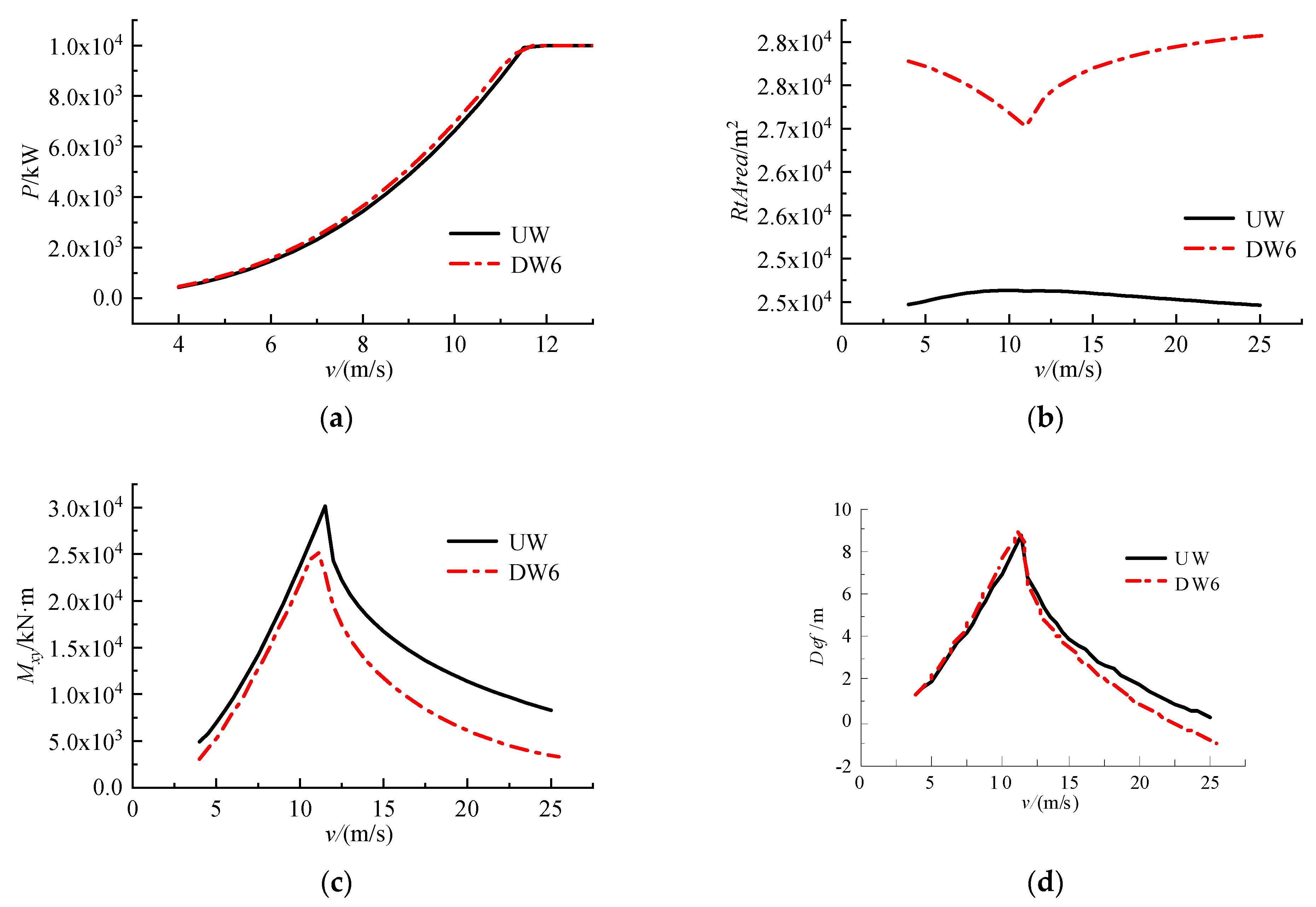
To study the influence of the downwind rotor on the aerodynamic performance of the wind turbine, the performances of the DW and UW are simulated in the steady-state operating conditions. The obtained results are shown in Figure 2.
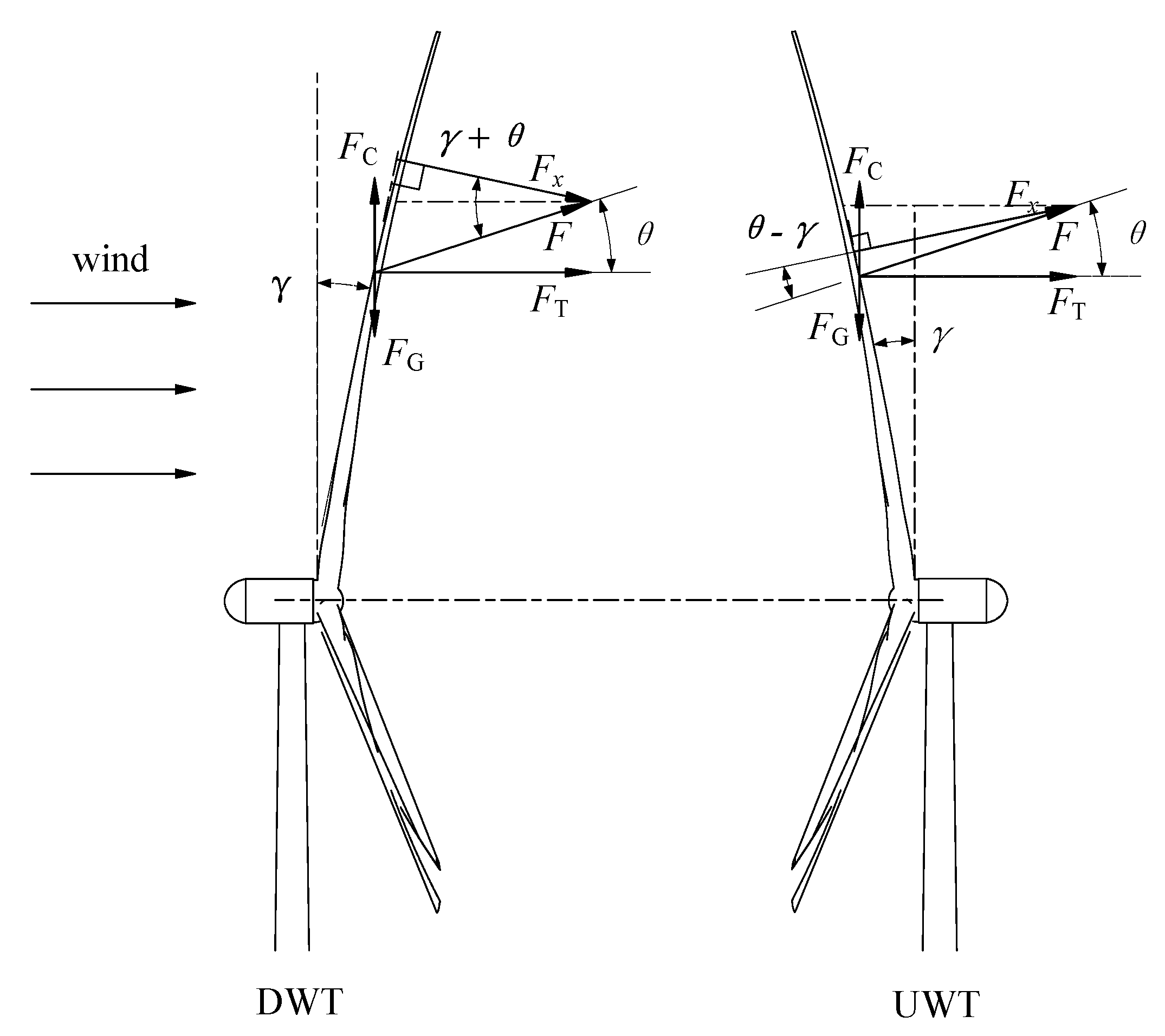
It can be seen from Figure 2a that the power output of the DW is smaller than that of the UW when the operating wind speed is lower than the rated wind speed, due to the negative influence of the tower shadow and the reduction of the rotor swept area. The maximum power loss is 4.1% and annual energy production loss is 1.57%. The swept area of the downwind rotor is mainly affected by the structure of the rotor. As shown in Figure 3, the blade bends in downwind due to the flapping load, and the flapping load of the blade is affected by the pitch control, which increases first and then decreases, resulting in the swept area of the downwind rotor first decreasing and then increasing, as shown in Figure 2b. However, the upwind rotor has the opposite result. It can be observed from Figure 2c that the peak load at the blade root of the DW is reduced by 22.54%. This is because the rotor cone angles make the DW’s rotor reduce the angle between the blade net force and the blade axis, as shown in Figure 3. The blade flapping load is F x = F cos ( θ γ ) in UWTs, while the blade flapping load is F x = F cos ( θ + γ ) in DWTs. Generally, 0 < θ γ < θ + γ < π 2 , so the peak load at the blade root of the DWT is less than that of the UWT. In addition, the DW case has a smaller rotor swept area (cf. Figure 2b). To ensure the same rated power output of the DW and UW case when operating at an over-rated wind speed, the DW case must have better aerodynamic performance than the UW case. Therefore, the pitch angle of the DW is slightly smaller than that of the UW at the same wind speed when operating at an over-rated wind speed, as shown in Figure 2d.

3.2. Comparison of Baseline Upwind Rotor and Downwind Rotor with Extended Blades

Since the downwind rotors have smaller rotor swept areas and power outputs, and the peak load at the blade root in the DW case is 22.54% lower than that in the UW case. To make both DW and UW cases have a same rated wind speed, the blade aerodynamic shape parameters (including blade length, chord length and blade pre-bend) of the DW are increased by 6%, hence the case is denoted as DW6. In addition, the blade stiffness of DW6 is redesigned so that the blade weight of DW6 is the same as that of UW.
The output power curves of DW6 and UW are shown in Figure 4a. They have the same rated power and rated wind speed. Because the downwind rotors have larger rotor swept area (cf. Figure 4b), the power output of DW6 is larger than that of UW when the wind speed is lower than the rated speed, and the annual energy production of DW6 is 1.67% higher than the UW. Although the DW6 blade is longer, its blade root load is smaller due to the downwind structure and the 2.5° cone angle. Compared with the upwind rotor, the blade root load can be reduced by up to 14.82% (cf. Figure 4c). Although its blade root flapping load is slightly smaller than UW when the wind speed is lower than the rated speed, because the relative stiffness of DW6 is smaller, the blade tip deflection in flapping direction of DW6 is still larger than that of UW, and the peak blade tip deflection increases by 3.79% (cf. Figure 4d). Due to the combined effect of the cone angle γ and the pitch control at over-rated wind speed, DW6 has greater reduction rate of the blade root flapping load than that of UW with increasing wind speed and DW6 has a much smaller blade root flapping load than that of UW. Therefore, the blade tip deflection of DW6 is smaller than that of UW.

3.3. Comparison of Downwind Rotors with Rotor Cone Angle Control and with Pitch Control

Figure 5 presents the performance simulation results of the DWC with rotor cone angle controller and the DW with pitch controller in the operating wind speed ranges.
It can be seen from Figure 5a that they have the same power output when the wind speed is lower than the rated speed because the blades of the DWC and DW are the same and both operate in the optimal tip speed ratio state with variable speed control (cf. Figure 5c,d). When the wind speed exceeds the rated speed, the blade root load of the DWC rapidly decreases due to the increasing rotor cone angle. The blade root load reaches the minimum value at the wind speed of 16 m/s (cf. Figure 5b), where the flapping moment of blade root My is approximately 0. As the wind speed and rotor cone angles continue to increase (cf. Figure 5d), the contribution of the centrifugal force FC of the blade to the blade root flapping moment My gradually increases, and the blade root flapping moment increases in the opposite direction, causing the blade root load to increase.

3.4. Comparison of Downwind Rotors with Normal and Improved Rotor Cone Angle Control

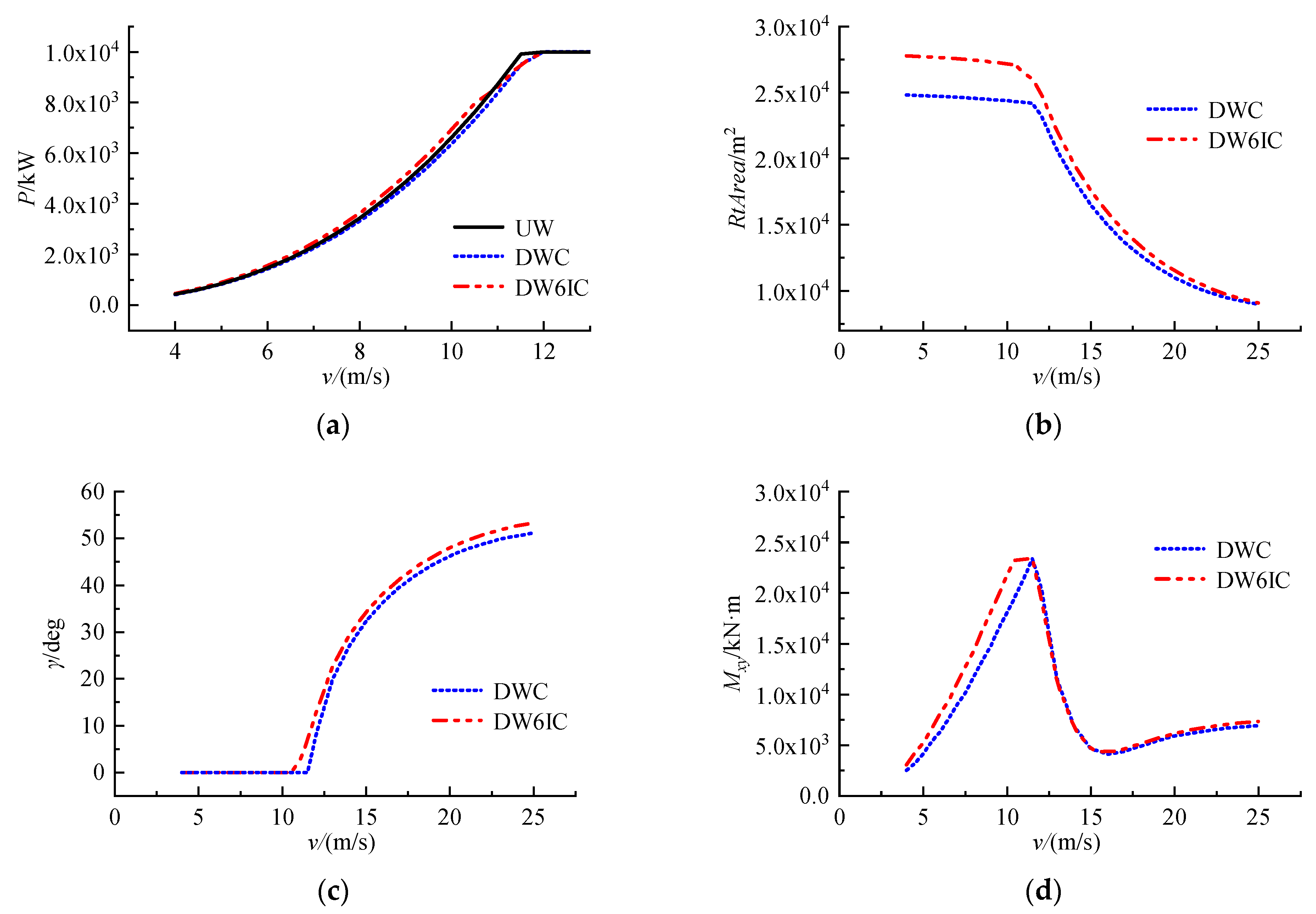
The load at the blade root in the DWC case with the rotor cone angle control decreases rapidly when it operates at the over-rated wind speed. The DWC presents the smallest peak load (23,400 kN·m) at the blade root as well when compared with the UW and DW6 cases. To compensate the power output loss of the DWC case and to keep the minimum peak load at the blade root, the DW6IC case is introduced in the paper. DW6IC has the same rotor as DW6 but use the improved rotor cone angle control rather than pitch control in DW6. To make the peak load at the blade root in the DW6IC case not higher than 23,400 kN·m, the wind speed where begins the executing rotor cone angle control of the DW6IC is smaller than that of the DWC (cf. Figure 6c).
The simulation results of the DW6IC are shown in Figure 6. In Figure 6a, the power output of DW6IC is larger than that of UW and DWC before it executes rotor cone angle control due to the larger blade length and swept area of DW6IC (cf. Figure 6b). However, when the blade root load of DW6IC reaches 23,400 kN·m, DW6IC increases the rotor cone angle to limit its blade root load (cf. Figure 6c). The power output of DW6IC is gradually smaller than UW until it reaches the rated wind speed. However, the annual energy production of DW6IC is still 1.12% higher than that of UW and 2.72% higher than that of DWC. As shown in Figure 6c, the rotor cone angle of DW6IC is slightly larger than that of DWC when it operates at an over-rated wind speed, because the blade length of DW6IC is 6% longer than that of DWC and has a larger swept area. Therefore, larger rotor cone angles are required to reduce the sweep area and aerodynamic efficiency of the rotor to limit the power output.
Furthermore, the DW6IC case executes the rotor cone angle control to make it the same peak load at the blade root as in DWC when the wind speed is lower than the rated speed, and DW6IC has larger rotor cone angles when it operates at an over-rated wind speed. Therefore, the blade root load curves in both DW6IC and DWC cases are similar when the wind speed is greater than the rated wind speed, reaching the minimum value at the wind speed of 16 m/s. As the wind speed and rotor cone angles continue to increase, the reverse blade root flapping moment of DW6IC starts to be larger than that of DWC, resulting in DW6IC’s blade root load 6.11% larger than DWC at 25 m/s, as shown in Figure 6d.

3.5. Discussion

The simulation results of five cases under the wind conditions shown in Table 2 are shown in Table 4.
Under the same conditions of rotor parameters, although the power output of DW is lower than that of UW and annual energy production loss is 1.57% due to the tower shadow and the reduction of the rotor swept area, the peak load of the blade root is reduced by 22.54%, which proves that the DWT has advantages in reducing the load. The DW6 is 6% longer than the DW blade, making up for the power output loss of DW. Compared with DW, the annual energy production of DW6 increased by 3.29%, but the peak load of blade root also increased by 9.97%. Under the condition of the same blade weight of DW6 and UW, the peak load of the blade root of DW6 decreased by 14.82%, and the annual energy production increased by 1.67%. Therefore, under steady-state operation conditions, DW6 has better performance.
In addition, DWC with rotor cone angle controller has the same aerodynamic performance as DW with pitch controller. However, DWC has larger reduction rate of the blade root load when the operating wind speed is over-rated, and the minimum blade root load is found at the wind speed of 16 m/s. DW6IC has the characteristic that the blade root load decreases faster with the wind speed with the rotor cone angle control.
DW6IC executes the rotor cone angle control when the wind speed is lower than the rated speed, resulting in DW6IC’s annual energy production 0.54% less than DW6. However, DW6IC’s blade root load is 8.96% less than DW6. Furthermore, under the condition that DW6IC has the same the peak load of the blade root as DWC, the annual energy production is increased by 1.12% and the peak load of the blade root is reduced by 22.54% compared with UW.

4. Conclusions

The DTU 10 MW wind turbine was used as the baseline model, and Open FAST was applied to simulate five cases that improve the rotor parameters and control strategy. By comparing the performance of these five cases (UW, DW, DW6, DWC, DW6IC), the effects of the rotor-cone-angle control on the power output and blade load of large-scale downwind wind turbine blades were analyzed, and the following conclusions were obtained:
  • The downwind rotor has great advantages in reducing the blade root load and the downwind blade can be longer and less stiffness because of the relaxed tower clearance constraint. The DW reduces the peak load of the blade root by 22.54% at the expense of annual energy production loss of 1.57%. The DW6 achieves 14.82% reduction in the peak load of the blade root and a 1.67% increase in annual energy production than UW under the same blade weight via extending the length of the blade and redesigning the mass and stiffness distributions of the blade.
  • The DWT has better performance by replacing pitch control with rotor cone angle control. The DWC with rotor cone angle controller has the same aerodynamic performance as the DW. However, it has greater reduction rate of blade root load at over-rated wind speed. It reaches the minimum blade root load at a wind speed of 16 m/s. Compared with the UW, the DW6IC with improved rotor cone angle control reduces the peak load of the blade root by 22.54%, and the annual energy production increases by 1.12%, which is more suitable for offshore wind farms with high wind speed.
Although downwind rotors are not extensively used, the advantages of the downwind structure, that they have no need to consider blade-tip deflection striking the tower, will become more obvious as modern commercial wind turbines continue to grow aggressively in size. The analysis of different examples in this paper proves the feasibility of the downwind structure and cone angle control, which can provide a reference for the design of large downwind rotors. The future work will be to further optimize the cone angle control strategy and apply it to the actual unit.

Author Contributions

Z.L. ran the codes and prepared this manuscript under the guidance of B.X. and X.S.; H.X., Z.H. and X.C. supervised the work and contributed to the interpretation of the results. All authors carried out data analysis, discussed the results, and contributed to writing the paper. All authors have read and agreed to the published version of the manuscript.

Funding

This research was funded by National Engineering Research Center for Offshore Windpower (grant number HSFD22004); the Fundamental Research Funds for the Central Universities (grant number B210202063); the Royal Society Grant IEC/NSFC/19140.

Conflicts of Interest

The authors declare no conflict of interest.

References

  1. Koh, J.H.; Ng, E.Y.K. Downwind offshore wind turbines: Opportunities, trends and technical challenges. Renew. Sustain. Energy Rev. 2016, 54, 797–808. [Google Scholar] [CrossRef]
  2. Bortolotti, P.; Ivanov, H.; Johnson, N.; Barter, G.E.; Veers, P.; Namura, N. Challenges, opportunities, and a research roadmap for downwind wind turbines. Wind Energy 2022, 25, 354–367. [Google Scholar] [CrossRef]
  3. Reiso, M.; Hagen, T.R.; Muskulus, M. A calibration method for downwind wake models accounting for the unsteady behaviour of the wind turbine tower shadow behind monopile and truss towers. J. Wind Eng. Ind. Aerodyn. 2013, 121, 29–38. [Google Scholar] [CrossRef]
  4. Dose, B.; Rahimi, H.; Herráez, I.; Stoevesandt, B.; Peinke, J. Fluid-structure coupled computations of the NREL 5 MW wind turbine by means of CFD. Renew. Energy 2018, 129, 591–605. [Google Scholar] [CrossRef]
  5. Dose, B.; Rahimi, H.; Stoevesandt, B.; Peinke, J. Fluid-structure coupled investigations of the NREL 5 MW wind turbine for two downwind configurations. Renew. Energy 2020, 146, 1113–1123. [Google Scholar] [CrossRef]
  6. Ning, A.; Petch, D. Integrated design of downwind land-based wind turbines using analytic gradients. Wind Energy 2016, 19, 2137–2152. [Google Scholar] [CrossRef]
  7. Bortolotti, P.; Bottasso, C.L.; Croce, A.; Sartori, L. Integration of multiple passive load mitigation technologies by automated design optimization-The case study of a medium-size onshore wind turbine. Wind Energy 2019, 22, 65–79. [Google Scholar] [CrossRef]
  8. Chetan, M.; Yao, S.L.; Griffith, D.T. Multi-fidelity digital twin structural model for a sub-scale downwind wind turbine rotor blade. Wind Energy 2021, 24, 1368–1387. [Google Scholar] [CrossRef]
  9. Xu, B.; Li, Z.; Zhu, Z.; Cai, X.; Wang, T.; Zhao, Z. The parametric modeling and two-objective optimal design of a downwind blade. Front. Energy Res. 2021, 9, 708230. [Google Scholar] [CrossRef]
  10. Namura, N.; Shinozaki, Y. Design optimization of 10 MW downwind turbines with flexible blades and comparison with upwind turbines. J. Phys. Conf. Ser. 2020, 1618, 042021. [Google Scholar] [CrossRef]
  11. Frau, E.; Kress, C.; Chokani, N.; Abhari, R.S. Comparison of performance and unsteady loads of multimegawatt downwind and upwind turbines. J. Sol. Energy Eng. 2015, 137, 041004. [Google Scholar] [CrossRef]
  12. Kress, C.; Chokani, N.; Abhari, R.S. Downwind wind turbine yaw stability and performance. Renew. Energy 2015, 83, 1157–1165. [Google Scholar] [CrossRef]
  13. Kress, C.; Chokani, N.; Abhari, R.S. Design considerations of rotor cone angle for downwind wind turbines. J. Eng. Gas Turbines Power 2016, 138, 052602. [Google Scholar] [CrossRef]
  14. Kress, C.; Chokani, N.; Abhari, R.S. Passive minimization of load fluctuations on downwind turbines. Renew. Energy 2016, 89, 543–551. [Google Scholar] [CrossRef]
  15. Kress, C.; Chokani, N.; Abhari, R.S.; Hashimoto, T.; Watanabe, M.; Sano, T.; Saeki, M. Impact of flow inclination on downwind turbine loads and power. J. Phys. Conf. Ser. 2016, 753, 022011. [Google Scholar] [CrossRef]
  16. Larwood, S.; Chow, R. Reconsidering downwind operation by analysis of the National Renewable Energy Laboratorys Phase VI data. Wind Eng. 2019, 43, 133–146. [Google Scholar] [CrossRef]
  17. Anderson, B.; Branlard, E.; Vijayakumar, G.; Johnson, N. Investigation of the nacelle blockage effect for a downwind turbine. J. Phys. Conf. Ser. 2020, 1618, 062062. [Google Scholar] [CrossRef]
  18. Wang, Z.Y.; Tian, W.; Hu, H. A comparative study on the aeromechanic performances of upwind and downwind horizontal-axis wind turbines. Energy Convers. Manag. 2018, 163, 100–110. [Google Scholar] [CrossRef]
  19. Rasmussen, F.; Petersen, J.T.; Vølund, P.; Leconte, P.; Szechenyi, E.; Westergaard, C. Soft Rotor Design for Flexible Turbines: Final Report; Risø National Laboratory: Roskilde, Denmark, 1998. [Google Scholar]
  20. Ichter, B.; Steele, A.; Loth, E.; Moriarty, P.; Selig, M. A morphing downwind-aligned rotor concept based on a 13-MW wind turbine. Wind Energy 2016, 19, 625–637. [Google Scholar] [CrossRef]
  21. Loth, E.; Steele, A.; Qin, C.; Ichter, B.; Selig, M.S.; Moriarty, P. Downwind pre-aligned rotors for extreme-scale wind turbines. Wind Energy 2017, 20, 1241–1259. [Google Scholar] [CrossRef]
  22. Noyes, C.; Loth, E.; Martin, D.; Johnson, K.; Ananda, G.; Selig, M. Extreme-scale load-aligning rotor: To hinge or not to hinge? Appl. Energy 2020, 257, 113985. [Google Scholar] [CrossRef]
  23. Noyes, C.; Qin, C.; Loth, E. Pre-aligned downwind rotor for a 13.2 MW wind turbine. Renew. Energy 2018, 116, 749–754. [Google Scholar] [CrossRef]
  24. Qin, C.C.; Loth, E.; Zalkind, D.S.; Pao, L.Y.; Yao, S.; Griffith, D.T.; Selig, M.S.; Damiani, R. Downwind coning concept rotor for a 25 MW offshore wind turbine. Renew. Energy 2020, 156, 314–327. [Google Scholar] [CrossRef]
  25. Hoghooghi, H.; Chokani, N.; Abhari, R.S. Effectiveness of individual pitch control on a 5 MW downwind turbine. Renew. Energy 2019, 139, 435–446. [Google Scholar] [CrossRef]
  26. Hoghooghi, H.; Chokani, N.; Abhari, R.S. Enhanced yaw stability of downwind turbines. J. Phys. Conf. Ser. 2019, 1356, 012020. [Google Scholar] [CrossRef]
  27. Bak, C.; Zahle, F.; Bitsche, R.; Kim, T.; Yde, A.; Henriksen, L.C.; Hansen, M.H.; Blasques, J.P.A.A.; Gaunaa, M.; Natarajan, A. Description of the DTU 10 MW Reference Wind Turbine; DTU Wind Energy Report-I-0092; Technical University of Denmark Wind Energy: Roskilde, Denmark, 2013. [Google Scholar]
  28. Bortolotti, P.; Kapila, A.; Bottasso, C.L. Comparison between upwind and downwind designs of a 10 MW wind turbine rotor. Wind Energy Sci. 2019, 4, 115–125. [Google Scholar] [CrossRef] [Green Version]
  29. Jonkman, J.M.; Buhl, M. FAST User’s Guide; National Renewable Energy Laboratory: Golden, CO, USA, 2005. [Google Scholar]
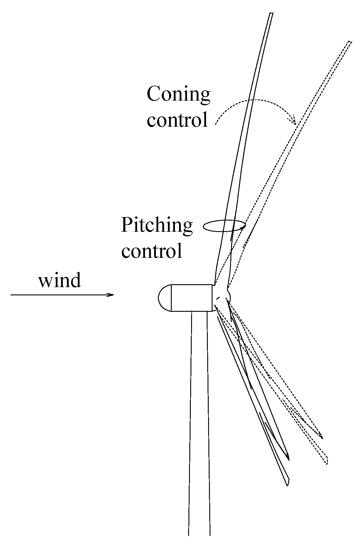
Figure 1. Schematic of pitching control and coning control.
Energies 15 06830 g001
Figure 2. (a) Output power curves. (b) Rotor swept area curves. (c) Loads of blade root curves. (d) Pitch angle curves.
Energies 15 06830 g002
Figure 3. Influence of rotor cone angle on blade load.
Energies 15 06830 g003
Figure 4. (a) Output power curves. (b) Rotor swept area curves. (c) Loads of blade root curves. (d) Blade tip deflection in the flapping direction curves.
Energies 15 06830 g004
Figure 5. (a) Output power curves. (b) Loads of blade root curves. (c) Pitch angle and cone angle curves of DW. (d) Pitch angle and cone angle curves of DWC.
Energies 15 06830 g005
Figure 6. (a) Output power curves. (b) Rotor swept area curves. (c) Rotor cones angle curves. (d) Loads of blade root curves.
Energies 15 06830 g006
Table 1. Main parameters of the DTU 10 MW wind turbine.
Param. *ValueParam.Value
Prated (MW)10B3
Drotor (m)178.3Rhub (m)2.8
γ (°)2.5T (°)5
Vrated (m/s)11.4Ωrated (rpm)9.6
Vin (m/s)4Vout (m/s)25
* Nomenclature in Table 1: Prated is the wind turbine rated power, B is the number of blades, Drotor is the rotor diameter, Rhub is the hub radius, γ is the rotor cone angle, T is the tilt angle, Vrated is the rated wind speed, Ωrated is the rotor rated rotational speed, Vin is the cut-in wind speed, and Vout is the cut-out wind speed.
Table 2. Basic parameters of wind resource at the site.
Param.ValueParam.Value
Weibull scale parameter11.60Average wind velocity (m/s)10.10
Weibull shape parameter2.11Average wind power density (W/m2)1125
Table 3. Pairwise comparison of these five simulation cases.
Model ComparisonPerformance Analysis *Objective
UW vs. DWP/Mxy/RtArea/βInfluence of the downwind rotor on the wind turbines
UW vs. DW6P/Mxy/RtArea/DefPerformance of DWT with extended blades
DW vs. DWCP/Mxy/β/γFeasibility of downwind rotor cone angle control
DWC vs. DW6ICP/Mxy/RtArea/γPerformance of DWT improved downwind rotor cone angle control
* Nomenclature in Table 3: P is the wind turbine output power, Mxy is the blade root resultant moment of flapping moment My and edgewise moment Mx, RtArea is the rotor swept area, β is the pitch angle, and Def is the blade tip deflection.
Table 4. Case simulation results.
AEP (kW·h)∆AEP (%)Max-Mxy (kN·m)∆Max-Mxy (%)
UW5.05 × 107-3.02 × 10⁴-
DW4.98 × 107−1.57%2.34 × 10⁴−22.54%
DW65.14 × 1071.67%2.57 × 10⁴−14.82%
DWC4.98 × 107−1.57%2.34 × 10⁴−22.54%
DW6IC5.11 × 1071.12%2.34 × 10⁴−22.54%
Publisher’s Note: MDPI stays neutral with regard to jurisdictional claims in published maps and institutional affiliations.