Article

Dragonfly Algorithm-Based Optimization for Selective Harmonics Elimination in Cascaded H-Bridge Multilevel Inverters with Statistical Comparison

by
Muhammad Ayyaz Tariq
1,*,
Umar Tabrez Shami
1,
Muhammad Salman Fakhar
1,
Syed Abdul Rahman Kashif
1,
Ghulam Abbas
2,*,
Nasim Ullah
3,
Alsharef Mohammad
3 and
Mohamed Emad Farrag
4
1
Department of Electrical Engineering, University of Engineering and Technology, Lahore 54890, Pakistan
2
Department of Electrical Engineering, The University of Lahore, Lahore 54000, Pakistan
3
Department of Electric al Engineering, College of Engineering, Taif University, Taif 21944, Saudi Arabia
4
School of Computing, Engineering and the Built Environment C011, Glasgow Caledonian University, 70 Cowcaddens Rd, Glasgow G4 0BA, UK
*
Authors to whom correspondence should be addressed.
Energies 2022, 15(18), 6826; https://doi.org/10.3390/en15186826
Submission received: 23 August 2022 / Revised: 9 September 2022 / Accepted: 14 September 2022 / Published: 18 September 2022

Abstract

:
Harmonics worsen the quality of electrical signals, hence, there is a need to eliminate them. The test objects under discussion are single-phase versions of cascaded H-bridge (CHB) multilevel inverters (MLIs) whose switching angles are optimized to eliminate specific harmonics. The Dragonfly Algorithm (DA) is used to eradicate low-order harmonics, and its statistical performance is compared to that of many other optimization techniques, including Particle Swarm Optimization (PSO), Accelerated Particle Swarm Optimization (APSO), Differential Evolution (DE), and Grey Wolf Optimization (GWO). Various scenarios of the algorithms’ search agent population for inverters with seven, nine, and eleven levels of output voltages are comprehensively addressed in this research. No algorithm shows total dominance in every scenario. The DA is least impacted by the change in dimensions of the narrated problem.

1. Introduction

Harmonic content is an indicator of the quality of an electrical system and is affected by the nature of the load. It stipulates the extent to which the concerned waveform drifts from being a pure sinusoid. In selective harmonic(s) elimination (SHE), the earmarked harmonic(s) are abolished by having the fundamental component set to the desired value. The singled-out harmonics are mostly lower-order ones that are closer to the working frequency. Optimized switching is performed with pulse width modulation by ascertaining the optimum angles with the assistance of metaheuristic algorithms.
Multilevel inverters (MLIs) are preferred as their output waveform is closer to the perfect sinusoid with the increasing number of steps per cycle of their waveforms [1]. The number of steps at different voltage levels indicates the number of levels associated with the inverter. With the growing number of levels, more switches and switching angles need to be tracked in order to approach a pure sinusoid [1]. This paper presents a cascaded H-bridge (CHB) inverter for seven, nine, and eleven output voltage levels. Each H-bridge has four switches, shown in Figure 1, and can provide three different voltage levels. Such individual units are connected in series to increase the number of voltage levels further [2]. Complementary switches must have the same operational time to maintain symmetry.
CHB reduces voltage imbalance with a minimum number of capacitors in the circuit compared to other topologies like diode clamped, flying capacitor, etc. [2]. The output waveform of MLI has odd-quarter-wave symmetry, and the harmonic content equations are transcendental, having multiple maxima/minima and have been solved using various methods [3]. High voltage and power applications prefer the inclusion of MLIs because their output voltage waveform is in the vicinity of a pure sinusoid while employing a reduced switching frequency [4,5]. The literature is filled with topologies intended to obtain the desired multilevel voltage waveform, and the CHB technique is one of them [2].
A separate DC supply is attached to each H-bridge, which can be equal to or different from the other(s). Different pulse width modulation techniques have been put into use for switching inverters. Fourier analysis of phase voltage shows that the odd-quarter-wave symmetry results in the automatic deletion of even harmonics [6]. The remaining harmonics, especially low-order ones, are mitigated via programmed pulse width modulation or SHE through proper switching angles [7].
Historically, the iterative process known as the Newton–Raphson method has been deployed for solving non-linear equations linked with low-order harmonic components [8]. The lack of a strong initial guess has weakened the application of the aforementioned method for the problem examined here [9]. Moreover, the lack of randomness and lagging performance in the increased number of unknowns has increased the demand for an alternative procedure. Another popular technique that has been used for the generation of switching pulses is sinusoidal pulse width modulation, in which the sinusoid is compared with a triangular wave with a set of desired characteristics [3]. The lack of meticulous pulses augments total harmonic distortion. Optimization algorithms have filled up the space created by the shortcomings of the abovementioned methods. Particle Swarm Optimization (PSO) [10] is one of the earlier optimization processes that has been deployed for figuring out the optimized angles needed to solve the SHE problem. The modus operandi for PSO involves a swarm of the desired number of particles interacting. Each particle has a specific velocity and location, which is updated based on personal and global best criteria after each iteration [10]. In [11], two H-bridges were cascaded, and PSO was applied to diminish the desired low-order harmonics in an effort to reduce the total harmonic distortion using varying values of the modulation indices.
Field programmable gate arrays (FPGAs) served as tests, and the switching was performed multiple times in the period of a quarter cycle, depending on the number of contents to be removed. In the following equation, the number of inverter levels is represented by the variable 𝑙. The number of H-bridges deployed according to the number of inverter levels is represented by the variable 𝑠 [12].
s = l 1 2
As the number of unknown angles grows with the levels of inverter and harmonics to be dealt with, eliminating all odd harmonics results in many angles to be found. The low-order harmonics (3rd, 5th, etc.) are considered the primary target, whereas the high-order ones are removed by a filter [13]. Accelerated Particle Swarm Optimization (APSO), Differential Evolution (DE), and Grey Wolf Optimization (GWO) have also been used in SHE [14,15,16]. By concentrating the role of algorithms only for the neighboring harmonics of a system frequency, a reduced size filter is required to cut out the remaining harmonic content because smaller constituent components are needed [17]. The Dragonfly Algorithm (DA) is based on the swarming technique of dragonflies and has already been used for the optimal placing and sizing of distributed generation [18] and in studies of optimal power flow [19]. PSO, APSO, DE, GWO, and the DA are deployed here in an effort to find the optimized switching angles exhibited through the positions of globetrotters involved in the algorithms.
This article applies the DA to solve the SHE problem in three different scenarios involving cascaded H-bridge multilevel inverters (CHBMLIs). The results are then compared with the findings from the other four algorithms. The DA is the latest algorithm discussed here and has the additional feature of moving the search agents away from the worst results obtained in each iteration [20]. Detailed characteristics of all algorithms are discussed later in this paper. The paper is structured as follows: the SHE problem is explained in Section 2. The methods deployed are explained in Section 3. The problem is determined with the assistance of all the mentioned optimization algorithms in Section 4. The methods above are juxtaposed via the aid of a statistical approach in Section 4. The conclusion is drawn in Section 5.

2. Selective Harmonics Elimination Problem

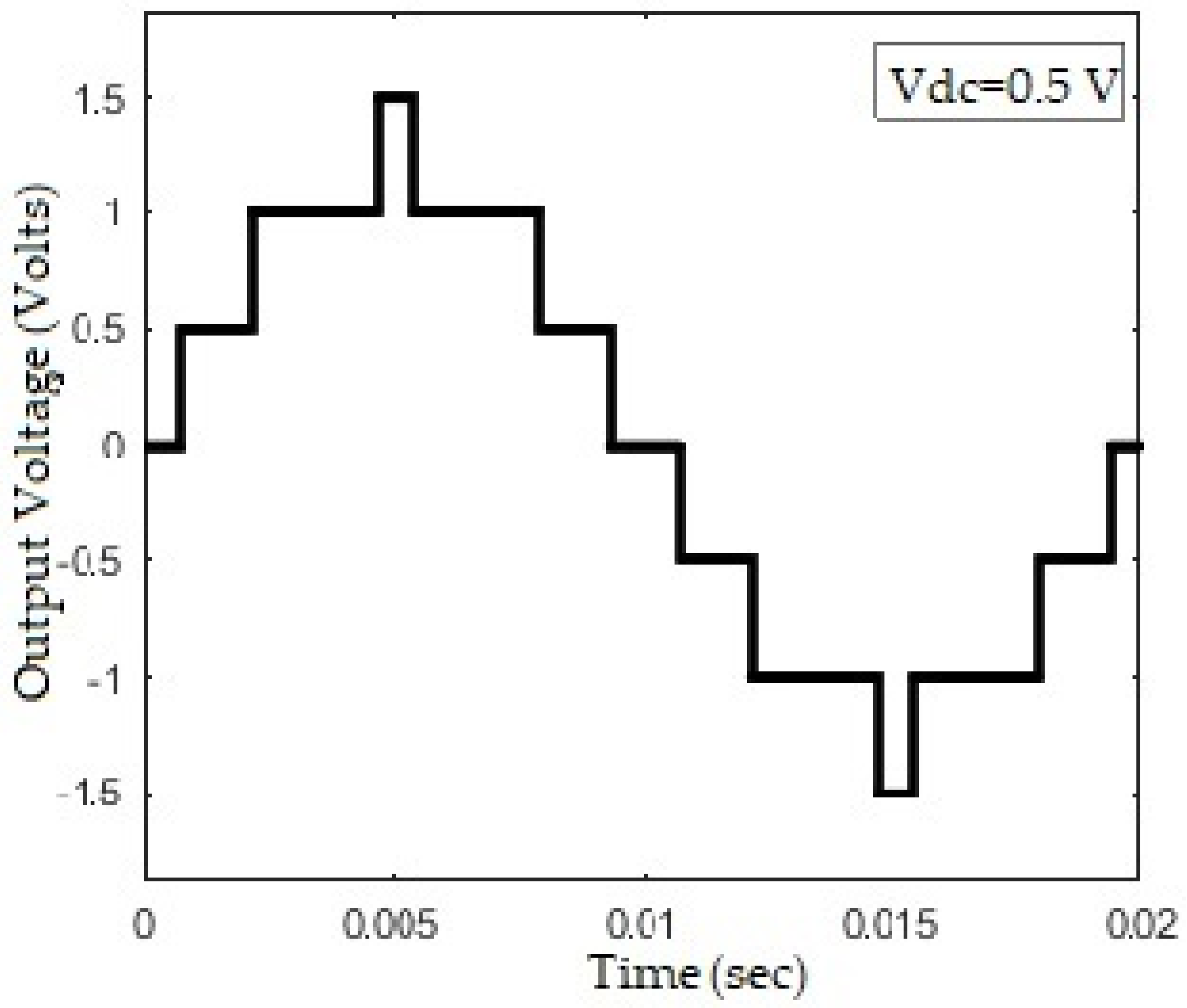
It can be seen that the waveform of MLI has quarter-wave-symmetry, as shown in Figure 2.
The Fourier analysis of such a waveform shows that only odd components are left to be treated. According to [1]:
V n = i = 1 s cos ( n α i )
and
f ( t ) = n = 1 V n sin ( 2 π n f t )
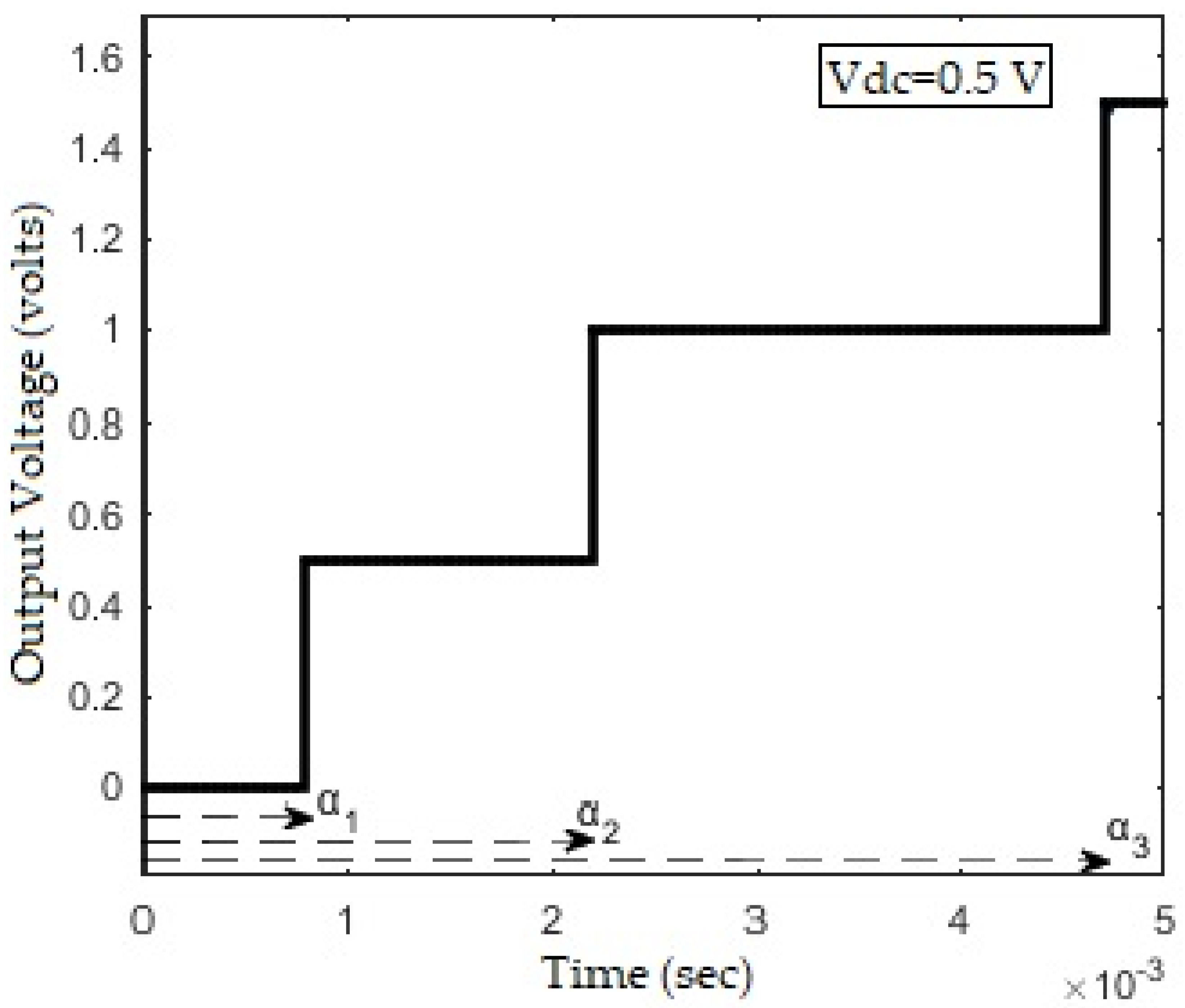
where V n is the amplitude of nth harmonic, and 𝑓(𝑡) is the Fourier expansion function. 𝛼 is the switching angle, i is the switching angle number, 𝑠 is the number of H-bridges used, and 𝑘 is a factor depending on the dc supply connected to the bridge. The harmonic number is given by 𝑛, which only consists of odd harmonics because of the symmetry mentioned above. There are three switching instants in the first quarter of one cycle, as shown in Figure 3. According to Equation (1), the harmonic components V 1 , V 3 , and V 5 are linked with the angles α 1 , α 2 , and α 3 respectively. The same link is developed for the increased number of levels, harmonics, and switching angles. Fundamental component aside, the rest of the desired low-order harmonics are made to equal zero by setting the following condition:
i = 1 s cos ( n α i ) = 0
where 𝑛 is odd and does not include the fundamental component. The fundamental component V 1 is set according to the modulation index and is given by:
i = 1 s cos ( α i ) = s ( π 4 ) M
where M = V / ( s V d c ) is the modulation index, 𝑉 is the desired value of the fundamental component, and V d c is the value of the DC supply. Equations (4) and (5) are the transcendental equations solved in terms of the switching angles by the aforementioned algorithms.
The problem under discussion concerns multimodal NP-hard optimization in the search for optimized switching angles, which are the solutions of the following equations in the case of a single phase 7-level inverter:
  cos ( α 1 ) + cos ( α 2 ) + cos ( α 3 ) = ( 3 π 4 ) M
and the other two are:
  cos ( 3 α 1 ) + cos ( 3 α 2 ) + cos ( 3 α 3 ) = 0
and
cos ( 5 α 1 ) + cos ( 5 α 2 ) + cos ( 5 α 3 ) = 0
The following condition must be fulfilled:
α 1 < α 2 < α 3 π 2
Equations (6)–(8), which are expansions of (4) and (5), indicate the fundamental component and lower-order odd harmonics. Equation (9) indicates that the switching involving three angles in increasing order is done within a quarter of the cycle. The number of switching angles equals the number of H-bridges employed in the circuit, which, according to Equation (1), is three for a 7-level inverter as indicated by Equation (9). The objective function is the summation of the absolute values of the fundamental and harmonic components. After the angles are found they are fed into the CHBMLI structure involving pulse generation depending on the number of switches and bridges. The values of angles give the working durations for the high state switches and the moments at which they turn ON. The exact process is repeated for the 9-level inverter with the addition of another bridge as indicated by Equation (1), and Equations (6)–(9) are modified. Augmentation of another H-bridge or switching angle enables us to eliminate another lower-order harmonic, and all the switching must be performed within a quarter of a cycle. Here the 7th harmonic is also targeted. A similar procedure is repeated for the 11-level inverter by augmenting another bridge, and the 9th harmonic is additionally targeted.

3. Methodology

This section presents the details about all the mentioned algorithms, including the equations and terminologies.

3.1. Particle Swarm Optimization

Particle Swarm Optimization is based on swarming behavior similar to the schooling of sea animals and birds using the deployment of randomness along with the interaction among search particles [10]. Each particle’s current position and velocity are updated via personal and global best locations [10]. The collection of desired switching angles is hidden in the particle’s location for which the concerned objective function reaches its desired value [10]. The advantages of this search technique include flexibility in handling closely related problems, efficient global search, and effectively dealing with any discontinuity. In contrast, lagging introduces the critical factor of a weak local search that results in optimization only on a partial level. The generic equations that are linked with the named algorithm are [10]:
v i t + 1 = v i t + a β 1 . [ g x i t ] + b β 2 . [ x p x i t ]
and
x i t + 1 = x i t + v i t + 1
where v i is i th particle’s current velocity, x i is i th particle’s current location, g is the global best value, x p is the personal best value, . indicates entry-wise product, t is the iteration number, a and b are constants, whereas β 1 and β 2 are random vectors with each member within 0 and 1 [10]. Its pseudocode present in the literature is:
  • Initialize positions and velocities for each particle.
  • Find the personally fittest and globally fittest particles.
  • Set the termination criterion.
  • Start the iterations.
  • Deploy Equations (10) and (11) to get new positions of each particle.
  • Repeat the second step and jump to the fifth step.
  • Repeat the sixth step until termination is reached.
  • Consider the globally fittest position as the answer.
For a seven-level inverter, the SHE system is linked with the narrated algorithm by considering [ α 1 , α 2 , α 3 ] hidden inside x i , giving the lowest values for Equations (7) and (8). The global best is the lowest value of the harmonics’ absolute sum that has been achieved. For a nine-level inverter, the optimized location of best cost particle(s) gives the set of four switching angles [ α 1 , α 2 , α 3 , α 4 ] with the objective function being the same as before. Five switching angles are there for the inverter with eleven output voltage levels.

3.2. Accelerated Particle Swarm Optimization

This algorithm is a single update equation variant of canonical PSO [21]. It is mathematically written as:
x i t + 1 = ( 1 β ) x i t + β g + α ϵ
where α and β are constants and ϵ is a random number between 0 and 1. The variable x i is i th particle’s current location, g is the global best value, and t is the iteration number. The pseudo-code is as follows:
  • Initialize the position for each particle and set the parameter values.
  • Find the fitness function value for each particle.
  • Find the globally fittest particle.
  • Update the position of each particle by using Equation (12).
  • Repeat the above three steps till the stopping criterion is reached.
  • Note down the position of the globally fittest particle.
The globally fittest particle at the end of this process envelops the switching angles that are used to calculate the desired switching intervals and instants to eliminate the specified harmonics.

3.3. Differential Evolution Algorithm

Differential evolution is free from the involvement of derivatives, and the processes involved in this algorithm are mutation, cross-over, and selection [22]. The following equation depicts the mutation involved in this algorithm:
y i t + 1 = x 1 t + W ( x 2 t x 3 t )
where x 1 t is the vector that performs best for the iteration t according to the defined objective and x 2 t and x 3 t are the randomly chosen vectors for that particular iteration. The variable W is varied between 0 and 1. It is called differential weight and includes the impact of the current and total number of iterations. A comparison between a predefined parameter and a random number defines the cross-over procedure [22]. The predefined parameter is called the cross-over parameter and is kept between 0 and 1. A mutated vector version is deployed if the parameter exceeds the random number [22]. Otherwise, this process has no impact. In the present scenario, the selection process compares the objective function value with the existing and updated vector. Since this is a minimization problem, the new current vector is chosen to be the one giving a lesser objective function value. The pseudo-code is written as:
  • Initialize the population randomly.
  • Set the differential weight and cross-over parameters to desired values.
  • Start the iterative process.
  • According to the defined procedure for the current iteration, choose the vectors x 1 , x 2 and x 3 .
  • Deploy Equation (13) to perform mutation.
  • Perform cross-over procedure.
  • Perform the selection process.
  • Repeat the four steps above until the stopping criterion is met.
  • Note down the fittest vector after the whole process.
The fittest vector contains information about the switching angles that are needed to eliminate the targeted harmonics.

3.4. Grey Wolf Optimization

GWO is inspired by the manner in which grey wolves hunt. This process involves tracking, encircling, and attacking the prey. Encircling can be mathematically summarized as [23]:
y i t = | c 1 t x p t x i t |
and
  x i t + 1 = x p t c 2 t y i t
where c 1 t and c 2 t are the coefficient vectors for iteration t . Variables x p t and x i t are position vectors for the prey and the grey wolves. The variable y i t is used to find the updated position of the grey wolves. The coefficient vectors are calculated via the following equations:
c 1 = 2 a r 1 a
and
c 2 = 2 r 2
where r 1 and r 2 are random vectors between 0 and 1, and a goes from 2 to 0 as iterations go from minimum to maximum. The solution provides the prey’s position which is obtained by giving equal weightage to the top three performers (alpha, beta, and gamma wolves) for the desired objective function in each iteration. A diverse selection of wolves is an added benefit of this algorithm. The pseudo-code is written as:
  • Initialize the population of grey wolves randomly.
  • Initialize the values of involved constants c 1 , c 2 , and a .
  • Calculate alpha, beta, and gamma wolves (the top three best value positions).
  • Start the iterations.
  • Calculate the prey’s position with the aid of alpha, beta, and gamma wolves (the top three best value positions at the current iteration).
  • Use Equations (14) and (15) to update the position of each grey wolf.
  • Update the constants involved.
  • Update alpha, beta, and gamma wolves’ positions.
  • Repeat the four steps above until the stopping criterion is met.
  • Note down the best vector after the whole process.
The best position obtained by GWO has the optimized switching angles that are fed inside the pulse generators to make the optimized waveform in MATLAB.

3.5. Dragonfly Algorithm

A relatively new algorithm, called the Dragonfly Algorithm, is based on the swarming behaviors of dragonflies that include hunting (static) and migration (dynamic) swarming [20]. In the former, dragonflies make small groups exploiting small areas to hunt; in the latter, many dragonflies move over a long distance. These characteristics form the basis of exploitation and exploration. The corrective patterns of dragonflies in a swarm include separation to avoid a collision, alignment for velocity matching, cohesion for moving towards the center of the neighborhood, attraction towards food, and distraction away from the predator [17,18,19,20]. The position of each fly is updated via step vector, which is obtained with each of the above patterns contributing in addition to the inertial factor as follows [20]:
X ( i , t + 1 ) = w X ( i , t ) + a A ( i , t ) + s S ( i , t ) + c C ( i , t ) + f F ( i , t ) + e E ( i , t )
where X i , A i , S i , C i , F i , and E i stand for the step, alignment, separation, cohesion, food attraction, and enemy distraction for i th dragonfly with w   (inertia), respectively, a ,   s ,   c ,   f , and e being the respective weights, and t is the iteration number. These weights are decided by including the impact of randomness and the number of iterations. Their values generally decrease as the process proceeds. The next location of a dragonfly is the sum of the step and current location.
S ( i , t ) is the negative sum of the distance of i th dragonfly with every neighbor in t th iteration. A ( i , t ) is given by the average velocity in t th iteration. C ( i , t ) is obtained through the distance of i th dragonfly from the average location in the neighborhood in t t h iteration. F ( i , t ) is calculated as the distance of i th dragonfly from a location with the best objective value so far in t th iteration to move towards the best location and E ( i , t ) is determined by finding the sum of the location of i th dragonfly and the location with the worst objective value so far in t th iteration to move away from it [17,18,19,20]. All the weights play an essential part in the convergence of the solution by controlling the nature of the swarm’s behavior. The radius of the neighborhood also depends on the point of procedure. In the absence of any neighbor, a random walk named Levy’s flight is performed [24]. As nature does not have a uniform distribution of resources, Levy’s walk introduces randomness when no neighbor is found. The current position is multiplied by the Levy parameter of randomness and is added to the current position to get the new location of the individual dragonfly [17,18,19,20]. A flowchart of the DA process is given in Figure 4, and the steps included in this process are:
  • Assign random locations to the dragonflies and find the fitness. Assign values to food and enemy.
  • Decide the stopping criterion and start iterations.
  • Update the weights based on iteration number and randomness.
  • In the presence of a neighbor, calculate ‘ A i ’, ‘ S i ’, ‘ C i ’, ‘ F i ’, and ‘ E i ’ for each fly. Update the position by adding the current position in Equation (18).
  • In the absence of a neighbor, assign a new position to dragonfly using a random walk.
  • Perform the third step and then the fourth or fifth step depending on the neighbor’s presence after updating food and enemy.
  • Repeat the above step till termination is reached.
  • Note down the food position.
Figure 4. Flowchart for Dragonfly Algorithm (DA).
Energies 15 06826 g004
The food position at the end of all steps contains the collection of desired switching angles. The number of switching angles depends on the dimensions of the problem.

4. Results and Discussion

The test system is run on MATLAB installed on an Intel (R) Core (TM) i5 CPU in a 2.50 GHz system with 4 GB RAM.

4.1. Implementation of Seven Level Inverter

The circuit is shown in Figure 5 and is similar to the one deployed in [13]. The fundamental component is set with a mostly deployed modulation index of 0.8. The objective function is the sum of the absolute values of the harmonics to be deleted and the desired setting of the fundamental component. For the seven-level inverter, 3rd and 5th harmonics are targeted. For 500 iterations, the best results obtained along with the respective switching angles for each of the narrated algorithms are tabulated in Table 1. The population mentioned is the one for which the particular best result is obtained. The computed switching angles are fed to the pulse generators via pulse widths and switching instants. A variable step (ode-45) solver is used to perform the FFT analysis, and the results obtained are stated in Table 2. All the algorithms are run 51 times for different population sizes with maximum iterations equal to 500, as the convergence patterns show lesser activity afterward. A sample size of 51 is chosen because it is moderate and also sets the degree of freedom [25] for the statistical test to a round number. Figure 6 summarizes the best objective function values for the seven-level inverter under every scenario.

4.2. Implementation of Nine Level Inverter

The modulation index is again chosen to be 0.8 for deciding the fundamental component value. In the present scenario, the 3rd, 5th, and 7th harmonics are treated along with the desired setting of a fundamental component inside the objective function. The maximum number of iterations is kept equal to 500. The rest of the settings are kept as described previously, and the results are in Table 3 and Table 4. Figure 7 summarizes the best objective function values for the nine-level inverter, and Figure 8 shows the results of the FFT analysis.

4.3. Implementation of Eleven Level Inverter

The modulation index is again set to 0.8 for corresponding the fundamental component value to the desired level. In the current scenario, the 3rd, 5th, 7th, and 9th harmonics are targeted along with the desired setting for the fundamental component in the objective function. The maximum number of iterations is set to 500. Table 5 and Table 6 show the results regarding harmonic percentages and switching angles for the eleven-level inverter. The best objective function values for an eleven-level inverter with all narrated algorithms under various scenarios of the population are summarized in Figure 9.

4.4. Statistical Comparison

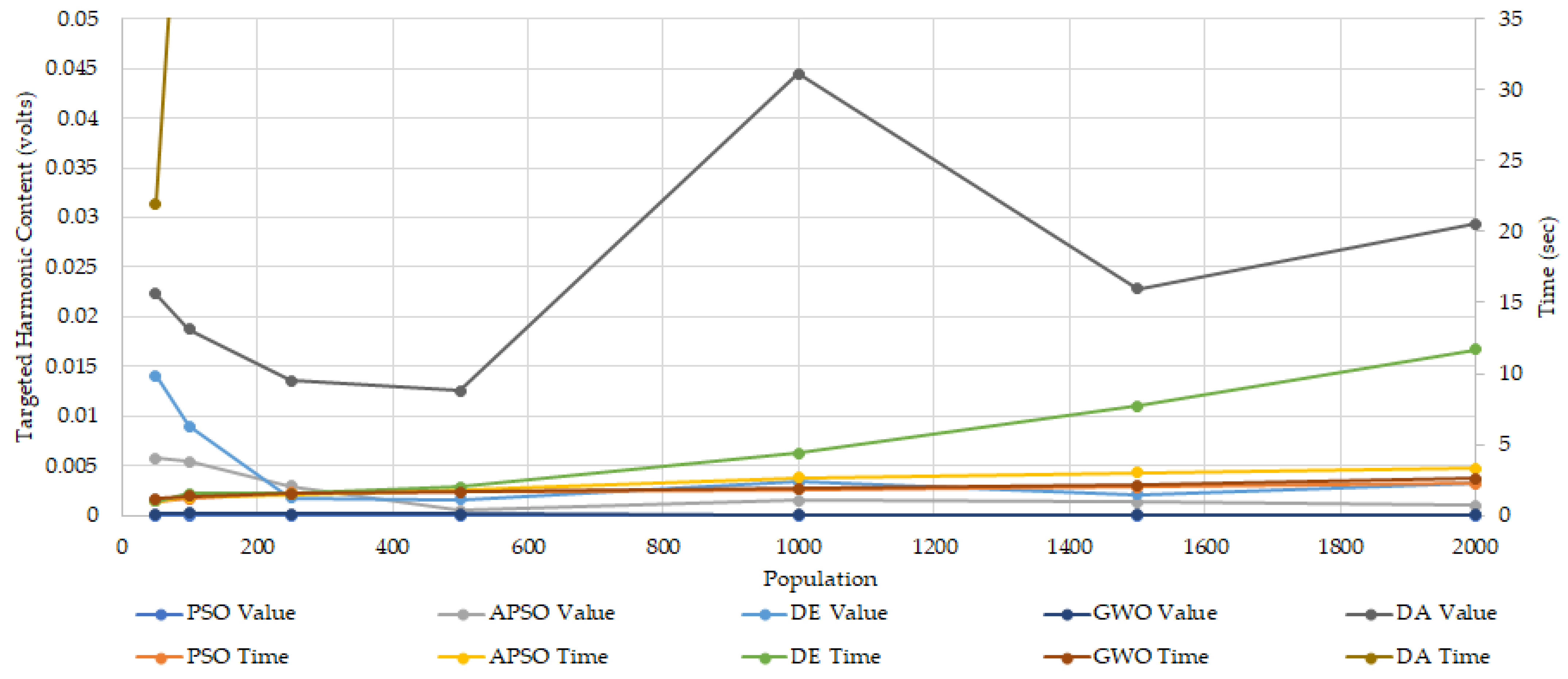
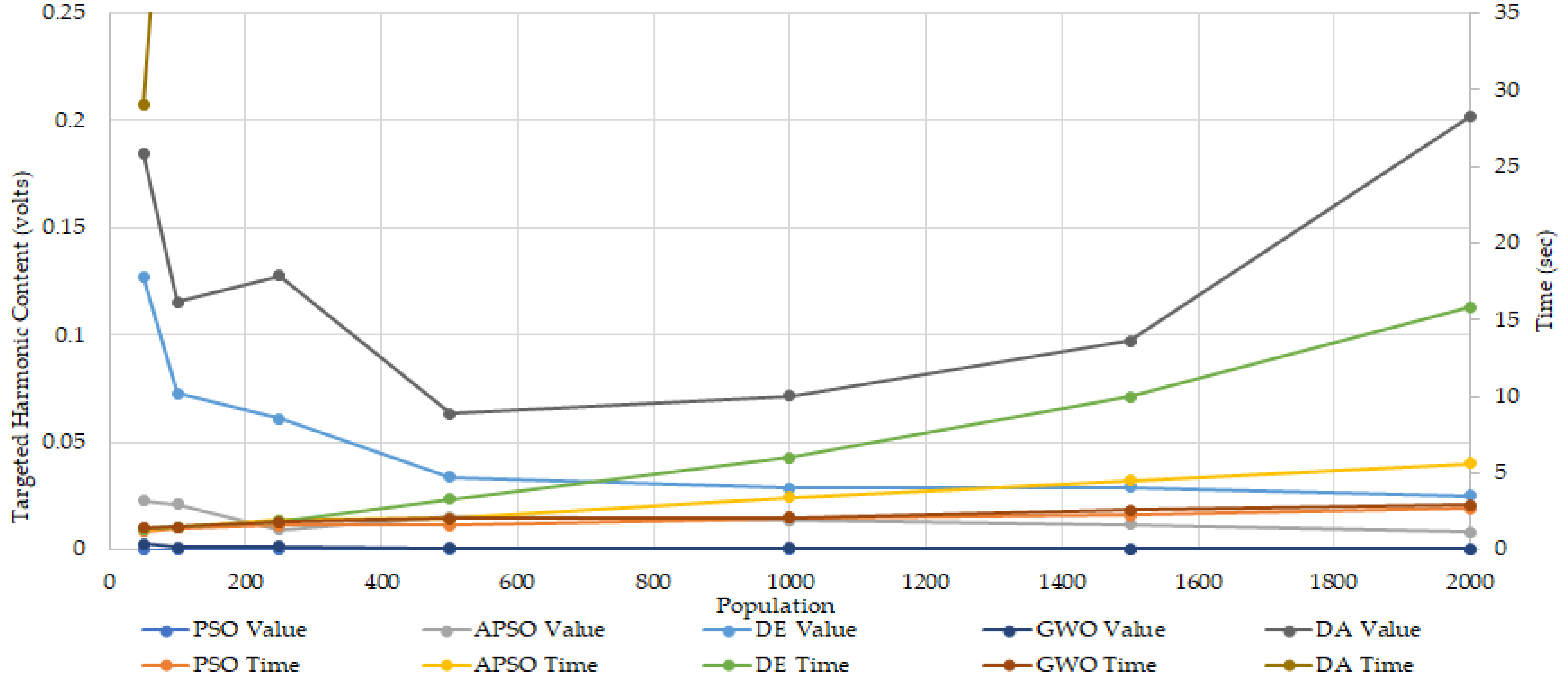
The average output values for all the mentioned algorithms run for every discussed level of the inverter are depicted in Figure 10, Figure 11 and Figure 12. The statistical comparison was made on IBM SPSS software, and an ANOVA test was used to compare the means of all algorithms with the most commonly used significance level of α = 0.05 [25]. Herein, each sample size is 51, and the comparison is performed for varying scenarios of generation sizes with 500 iterations. Rankings are assigned based on the post hoc test Tukey B a . This post hoc test compares all possible pairs of means and informs where the difference exists. The results are tabulated in Table 7. The first position means that the algorithm has performed best under that particular scenario. The joint position shows that the means are not different according to the set significance level. Overlapping positions mean that the result is on the verge and can be considered to have achieved any of the two positions.

4.5. Discussion

Table 2 shows that all the algorithms except the DA gave precisely the same harmonic elimination for a seven-level inverter. The DA gave a slightly better result for the 3rd harmonic but worse for the 5th one. If the fundamental is of immense value and the user is more concerned about the 3rd harmonic then, in that case, the DA does perform slightly better. Clearly, if the step size is decreased these harmonics will be mitigated, but here, the purpose is for comparison. Table 1 shows that the DA takes much more time to run under similar circumstances, and it is an inbuilt aspect because it considers more factors than the other discussed methods. Table 3 shows that DE gives the lowest harmonic percentages as its best result was under a nine-level inverter, with the DA in second place. The other three algorithms lag behind these two. Table 4 and Table 6 show that as the dimension of the problem increases, the DA lags slightly behind and takes much more time to complete the maximum iterations than others. In addition to Table 1, these tables also show that the DA’s results remain approximately stable under the variation in the dimensions of the problem while all other algorithms are impacted more. Table 7 shows that PSO, APSO, and GWO provide better average objective function values under all the scenarios followed by the DA. DE delivers the highest average values among the narrated methods in all discussed cases.
Moreover, these varying performances under different scenarios also validate the ‘No Free Lunch Theorem’ [26]. The DA takes more factors into account compared to other relatively more straightforward algorithms. In turn, this aspect affects its speed and increases its complexity.

5. Conclusions

The central aspect discussed and presented in this article is the DA’s performance comparison, the impacts of generation, the type of algorithm, and the dimension of the problem on the result obtained for the SHE problem. SHE is solved with the DA, and a comparison is made with four other algorithms under varying population numbers. The comparison is provided in tabular and graphical forms. The results show that different methods, populations, and dimensions impact the algorithms’ results. Even though the problems are similar, no algorithm shows total dominance in every scenario.
The best objective function values delivered by the DA remain stable under varying dimensions of the problem. On average, the DA performs better than DE for this problem but its best results lag. The performances of PSO, APSO, and GWO are good and nearly identical with regard to the average values and performance times. The GWO algorithm shows sustained dominance regarding the average output values. The DA takes much more time than other discussed algorithms.

Author Contributions

Conceptualization, M.A.T., U.T.S. and M.S.F.; methodology, M.A.T. and M.S.F.; software, M.A.T.; validation, G.A., M.S.F. and S.A.R.K.; formal analysis, M.E.F. and U.T.S.; investigation, M.A.T. and G.A.; resources, M.S.F., N.U. and A.M.; data curation, M.A.T. and M.S.F.; writing—original draft preparation, M.A.T.; writing—review and editing, G.A. and M.E.F.; visualization, M.A.T., M.S.F., S.A.R.K. and G.A.; supervision, M.S.F., S.A.R.K. and G.A.; project administration, S.A.R.K., G.A., N.U., A.M. and M.E.F.; funding acquisition, G.A., N.U. and A.M. All authors have read and agreed to the published version of the manuscript.

Funding

This research work is supported by Taif University Researchers Supporting Project number (TURSP-2020/144), Taif University, Taif, Saudi Arabia.

Data Availability Statement

Not applicable.

Acknowledgments

The authors acknowledge the financial support from Taif University Researchers Supporting Project Number (TURSP-2020/144), Taif University, Saudi Arabia. The authors would also like to acknowledge the support of Power Planners International Pvt. Limited, Shark Innovation Labs, Rukhsana Fakhar, and Hitachi Energy Pakistan Pvt. Limited for providing the funding for establishing the Power Systems Simulation Research Lab at the University of Engineering and Technology, Lahore. The computational resources of the lab have been used in this research.

Conflicts of Interest

The authors declare no conflict of interest.

References

  1. Tamilvani, P.; Valluvan, K.R. Harmonic Mitigation in Various Levels of Multilevel Inverter with Different Loads. Int. J. Innov. Res. Electr. Electron. Instrum. Control. Eng. 2014, 2, 1989–1996. [Google Scholar]
  2. Bughneda, A.; Salem, M.; Richelli, A.; Ishak, D.; Alatai, S. Review of Multilevel Inverters for PV Energy System Applications. Energies 2021, 14, 1585. [Google Scholar] [CrossRef]
  3. Malinowski, M.; Gopakumar, K.; Rodriguez, J.; Peres, M.A. A Survey on Cascaded Multilevel Inverters. IEEE Trans. Ind. Electron. 2010, 57, 2197–2206. [Google Scholar] [CrossRef]
  4. Kouro, S.; Malinowski, M.; Gopakumar, K.; Pou, J.; Franquelo, L.G.; Wu, B.; Rodriguez, J.; Peres, M.A.; Leon, J.I. Recent Advances and Industrial Applications of Multilevel Converters. IEEE Trans. Ind. Electron. 2010, 57, 2553–2580. [Google Scholar] [CrossRef]
  5. Konstantinou, G.S.; Dahidah, M.S.A.; Agelidis, V.G. Solution trajectories for selective harmonic elimination pulse-width modulation for seven level waveforms: Analysis and implementation. IET Power Electron. 2012, 5, 22–30. [Google Scholar] [CrossRef]
  6. Fei, W.; Ruan, X.; Wu, B. A Generalized Formulation of Quarter-Wave Symmetry SHE-PWM Problems for Multilevel Inverters. IEEE Trans. Power Electron. 2009, 24, 1758–1765. [Google Scholar] [CrossRef]
  7. Fei, W.; Du, X.; Wu, B. A Generalized Half-Wave Symmetry SHE-PWM Formulation for Multilevel Voltage Inverters. IEEE Trans. Ind. Electron. 2010, 57, 3030–3038. [Google Scholar]
  8. Hagh, M.T.; Taghizadeh, H.; Razi, K. Harmonic Minimization in Multilevel Inverters Using Modified Species-Based Particle Swarm Optimization. IEEE Trans. Power Electron. 2009, 24, 2259–2267. [Google Scholar] [CrossRef]
  9. Al-Hitmi, M.; Ahmad, S.; Iqbal, A.; Padmanaban, S.; Ashraf, I. Selective Harmonics Elimination in a Wide Modulation Range Using Modified Newton—Raphson and Pattern Generation Methods for a Multilevel Inverter. Energies 2018, 11, 458. [Google Scholar] [CrossRef]
  10. Yang, X.S. Introduction to Mathematical Optimization: From Linear Programming to Metaheuristics, 1st ed.; Cambridge International Science Publishing: Cambridge, UK, 2008; pp. 107–118. [Google Scholar]
  11. Ismail, B.; Hassan, S.I.S.; Ismail, R.C.; Haron, A.R.; Azmi, A. Selective Harmonic Elimination of Five-Level Cascaded Inverter Using Particle Swarm Optimization. Int. J. Engg. Tech. 2013, 5, 5220–5232. [Google Scholar]
  12. Maharana, M.K. PSO based Harmonic Reduction Technique for Wind Generated Power System. Int. J. Power Syst. Oper. Energy Manag. 2013, 2, 31–35. [Google Scholar] [CrossRef]
  13. Janjamraj, N.; Oonsivilai, A. Harmonic Elimination of Hybrid Multilevel inverters Using Particle Swarm Optimization. World Acad. Sci. Engg. Tech. Int. J. Electr. Comput. Energ. Electron. Comm. Engg. 2012, 6, 1461–1466. [Google Scholar]
  14. Madichetty, S.; Rambabu, M.; Dasgupta, A. Selective harmonic elimination: Comparative analysis by different optimization methods. In Proceedings of the IEEE 6th India International Conference on Power Electronics, Kurukshetra, India, 8–10 December 2014; pp. 1–6. [Google Scholar]
  15. Vijayakumar, R.; Devalalitha, C.; Nachiappan, A.; Mazhuvendhi, R. Selective harmonic elimination PWM method using two level inverter by differential evolution optimization technique. In Proceedings of the 2014 International Conference on Science Engineering and Management Research, Chennai, India, 27–29 November 2014; pp. 1–6. [Google Scholar]
  16. Routray, A.; Singh, R.K.; Mahanty, R. Harmonic Reduction in Hybrid Cascaded Multilevel Inverter Using Modified Grey Wolf Optimization. IEEE Trans. Ind. App. 2020, 56, 1827–1838. [Google Scholar] [CrossRef]
  17. Espinosa, C.A.L.; Portocarrero, I.; Izquierdo, M. Minimization of THD and angles calculation for multilevel inverters. Int. J. Engg. Tech. 2012, 12, 83–86. [Google Scholar]
  18. Amin, A.A.; Patel, R.K.; Vasavada, M.R. Optimal Placement and Sizing of Distributed Generation in Distributed Power System using Dragonfly Algorithm. Int. J. Innov. Res. Electr. Electron. Instr. Contr. Engg. 2017, 5, 197–203. [Google Scholar] [CrossRef]
  19. Bashishtha, T.K. Nature Inspired Meta-heuristic dragonfly Algorithms for Solving Optimal Power Flow Problem. Int. J. Electron. Electr. Comput. Syst. 2016, 5, 111–120. [Google Scholar]
  20. Asli, B.Z.; Haddad, O.B.; Chu, X. Dragonfly Algorithm (DA). In Advanced Optimization by Nature-Inspired Algorithms, 1st ed.; Haddad, O.B., Ed.; Springer: Singapore, 2018; Volume 720, pp. 151–159. [Google Scholar]
  21. Fakhar, M.S.; Kashif, S.A.R.; Liaquat, S.; Rasool, A.; Padmanaban, S.; Iqbal, M.A.; Baig, M.A.; Khan, B. Implementation of APSO and Improved APSO on Non-Cascaded and Cascaded Short Term Hydrothermal Scheduling. IEEE Access 2021, 9, 77784–77797. [Google Scholar] [CrossRef]
  22. Yang, X.S. Nature-Inspired Optimization Algorithms, 2nd ed.; Elsevier: Cambridge, MA, USA, 2020; pp. 101–109. [Google Scholar]
  23. Rezaei, H.; Haddad, O.B.; Chu, X. Grey Wolf Optimization (GWO) Algorithm. In Advanced Optimization by Nature-Inspired Algorithms, 1st ed.; Haddad, O.B., Ed.; Springer: Singapore, 2018; Volume 720, pp. 81–91. [Google Scholar]
  24. Jamil, M.; Zepernick, H.J. Levy Flights and Global Optimization. In Swarm Intelligence and Bio-Inspired Computation: Theory and Applications; Yang, X.S., Cui, Z., Xiao, R., Gandomi, A.H., Karamanoglu, M., Eds.; Elsevier: London, UK, 2013; pp. 49–72. [Google Scholar]
  25. Kerr, A.W.; Hall, H.K.; Kozub, S.A. Doing Statistics with SPSS, 1st ed.; Sage Publications Ltd.: London, UK, 2002; pp. 114–122. [Google Scholar]
  26. Yang, X.S. Engineering Optimization: An Introduction with Metaheuristic Applications, 1st ed.; Wiley: Hoboken, USA, 2010; pp. 25–27. [Google Scholar]
Figure 1. Structure of H-bridge.
Energies 15 06826 g001
Figure 2. Multilevel output voltage waveform.
Energies 15 06826 g002
Figure 3. Switching instants in a quarter of a cycle.
Energies 15 06826 g003
Figure 5. Seven-level inverter circuit.
Energies 15 06826 g005
Figure 6. Summary of algorithms’ performance for a seven-level inverter.
Energies 15 06826 g006
Figure 7. Summary of algorithms’ performance for a nine-level inverter.
Energies 15 06826 g007
Figure 8. FFT analysis for a nine-level inverter via DA.
Energies 15 06826 g008
Figure 9. Summary of algorithms’ performance for an eleven-level inverter.
Energies 15 06826 g009
Figure 10. Algorithms’ average performance for a seven-level inverter.
Energies 15 06826 g010
Figure 11. Algorithms’ average performance for a nine-level inverter.
Energies 15 06826 g011
Figure 12. Algorithms’ average performance for an eleven-level inverter.
Energies 15 06826 g012
Table 1. Optimized switching angles for seven-level cascaded H-Bridge (CHB) inverter.
Algorithmα1 (rad)α2 (rad)α3 (rad)Time (s)Best Result (V)Population
PSO0.23050.66401.447613.89 × 10−1650
APSO0.23050.66411.44761.85.26 × 10−4500
DE0.23090.66351.447121.565 × 10−3500
GWO0.23050.66401.44751.96.113 × 10−51000
DA0.23350.65921.44306101.257 × 10−2500
Table 2. Percentage harmonics (w.r.t. fundamental) for seven-level CHB inverter.
AlgorithmParticle Swarm
Optimization (PSO)
Accelerated Particle
Swarm Optimization (APSO)
Differential Evolution
(DE)
Grey Wolf Optimization
(GWO)
Dragonfly Algorithm
(DA)
3rd Harmonic0.19%0.19%0.19%0.19%0.18%
5th Harmonic0.07%0.07%0.07%0.07%0.47%
Table 3. Percentage harmonics (w.r.t. fundamental) for nine-level CHB inverter.
AlgorithmPSOAPSODEGWODA
3rd Harmonic0.44%0.66%0.11%0.44%0.24%
5th Harmonic0.36%0.26%0.14%0.36%0.27%
7th Harmonic0.47%0.06%0.14%0.47%0.18%
Table 4. Optimized switching angles for nine-level CHB inverter.
Algorithmα1 (rad)α2 (rad)α3 (rad)α4 (rad)Time (s)Best Result (V)Population
PSO0.18920.46000.92601.53801.66.25 × 10−16500
APSO0.18950.46040.92811.53945.68.23 × 10−32000
DE0.18570.46490.92241.533515.82.51 × 10−22000
GWO0.18910.46000.92591.53792.94.14 × 10−42000
DA0.19250.46380.94291.54836476.32 × 10−2500
Table 5. Percentage harmonics (w.r.t. fundamental) for eleven-level CHB inverter.
AlgorithmPSOAPSODEGWODA
3rd Harmonic0.08%0.12%0.11%0.08%0.3%
5th Harmonic0.2%0.23%0.15%0.21%0.36%
7th Harmonic0.31%0.3%0.38%0.3%0.41%
9th Harmonic0.08%0.15%0.00%0.08%0.31%
Table 6. Optimized switching angles for eleven-level CHB inverter.
Algorithmα1 (rad)α2 (rad)α3 (rad)α4 (rad)α5 (rad)Time (s)Best Result (V)Population
PSO0.01500.43380.61331.06201.57071.867.225 × 10−2250
APSO0.00640.43400.61201.06141.57076.97.81 × 10−22000
DE0.03050.43120.61521.06151.570712.51.07 × 10−11500
GWO0.01580.43380.61351.06201.570737.328 × 10−21500
DA0.000.43490.61271.06281.57078659.085 × 10−2500
Table 7. Statistical comparison for the average performance of algorithms.
InverterGenerationBest Average Ranking
PSOAPSODEGWODA
7 Levels501st1st/2nd4th2nd/3rd3rd
1001st1st3rd1st2nd
2501st1st/2nd4th2nd3rd
5001st1st3rd1st2nd
10001st1st3rd1st2nd
15001st1st3rd1st2nd
20001st1st3rd1st2nd
9 Levels502nd2nd3rd1st2nd
1002nd/3rd1st/2nd4th1st3rd
2501st1st3rd1st2nd
5001st1st3rd1st2nd
10001st1st3rd1st2nd
15001st1st/2nd4th2nd3rd
20001st1st3rd2nd3rd
11 Levels502nd2nd3rd1st2nd
1003rd2nd4th1st2nd/3rd
2502nd2nd3rd1st2nd
5002nd2nd3rd1st2nd
10002nd2nd4th1st3rd
15002nd2nd4th1st3rd
20002nd2nd3rd1st2nd
Publisher’s Note: MDPI stays neutral with regard to jurisdictional claims in published maps and institutional affiliations.