Abstract
This paper presents the integrated optimal design of the powertrain of a hybrid regional aircraft using multidisciplinary design optimization (MDO). The sizing of the main components of the propulsion chain is performed over the flight mission under various scenarios regarding energy management strategies and technological assessments. For that purpose, a complete set of multidisciplinary surrogate models are integrated into the MDO process, taking account not only of the main electrical, thermal and mechanical aspects but also of environmental constraints such as partial discharges in electric motors regarding flight conditions. Several MDO formulations are investigated comparing local (i.e., motor mass minimization) and global optimizations (i.e., powertrain mass then fuel burn minimization at aircraft level). Results emphasize main systemic couplings showing that despite future technological progress, the series hybrid architecture is heavier than a conventional thermal aircraft. Nevertheless, thanks to the whole aircraft optimization, potential gains related to kerosene consumption can be reached, reducing the environmental footprint. The “energy gains” focused on in this paper may be added with aerodynamic gains potentially involved in more electric powertrain. This work has been carried out in the frame of the HASTECS project under the Clean Sky II program which aims at reducing CO2 emissions and environmental impacts of the aviation sector.
1. Introduction
The transportation sector strongly contributes to environmental degradation. Finding sustainable and less polluting solutions is a key element in solving this problem, particularly for the aviation sector, which accounts for around 2% of global CO2 emissions [1]. COVID-19 has transiently slowed down air traffic and has strengthened the need to respect the environment as focused in the “Clean Sky” framework. The ACARE (Advisory Councilor Aviation Research and Innovation in Europe) sets environmental objectives for 2050 technologies with a 75% reduction in CO2 emissions per passenger kilometer and a 90% reduction in NOx emissions. The perceived noise emission of flying aircrafts should be reduced by 65%. These figures are relative to the capabilities of a typical new aircraft in 2000. More generally, the aviation industry actually faces the “revolution towards more electric aircrafts” [2,3,4,5,6,7,8]. In this context, more than 200 projects of electrically propelled aircrafts have emerged in recent years [3,8]. Some of them are supported by well-known industrial companies (Airbus, Boeing, Rolls Royce), others from start-ups or new companies born in the aeronautical industry. In the USA, NASA is also active with the “X-57 LEAPTECH” project investigating an aircraft with distributed propulsion [9]. In France, ONERA [10,11] also studies other aerodynamic concepts such as “Dragon” or “Ampere”.
1.1. Literature Review
Hybrid electric propulsion requires to integrate new technologies and new management capabilities to improve aircraft efficiency and performance, for example, by means of distributed propulsion. It limits burning of non-renewable fossil resources and reduces the environmental footprint of future aircrafts [8,9,10,11,12,13,14,15,16,17,18,19,20,21,22,23,24,25]. However, compared to a conventional aircraft, electrification leads to a significant increase of the aircraft mass with today’s technologies, which makes power integration a critical issue [8]. Consequently, new technologies for improving efficiencies and the specific power of aircraft components are needed. Moreover, this requires the optimization of the aircraft both at the component level and the system level. To overcome those challenges, multidisciplinary design optimization (MDO) approaches investigating the optimization of aircraft architectures with new technologies of components are of great interest. Such approaches have been specifically developed for optimizing complex systems taking account of multiple disciplinary fields and multiple design levels from the elementary components to the whole system [24,25,26,27,28,29,30,31,32,33,34]. However, most of these MDO studies are based on rough modelling assessing specific powers (kW/kg) or energies (kWh/kg) to couple the design of powertrain with aerodynamic structure and aircraft architecture in a whole MDO process. MDO approaches based on technological assessments are uncommon. Some studies focus on a specific part of the electrified powertrain, for example, on filtering devices [12] or electric machines [13]. Other papers analyze couplings between sizing and flight mission [17] or the influence of the EMS (energy management strategy) and operation strategies on hybrid electric aircraft performance [25]. In this paper, an MDO of the whole hybrid electric powertrain is proposed by means of technological models coupled with the EMS and regarding typical flight missions. Several optimization formulations are compared to minimize local (at electric motor level) or global (at powertrain level) embedded weight or to minimize the fuel burn during the flight.
1.2. Main Contributions
This paper explores the optimal design of the propulsion chain of a hybrid regional aircraft powered by both gas turbines and fuel cells. Technological models are “embedded” in an MDO process considering two target technologies for electrical and thermal components which forecast progressively the technological progress.
To summarize, the main contributions of this paper are:
- -
- The proposed MDO based on technological models which emphasize the innovation and sensitivity of technological progress in future hybrid electric aircrafts. Local optimizations (i.e., motor weight minimization) are compared with global optimizations (i.e., minimization of the whole powertrain, then fuel burn reduction at aircraft level). As previously mentioned, technological aspects are often quite simplified in the state of the art of the MDO process. The MDO process is introduced in Section 2;
- -
- Here, main physical fields (electrical, mechanical, thermal) and main environmental constraints (partial discharges, thermal limits, etc.) are integrated in technological models of the powertrain devices which assess weights and losses (efficiencies) in power electronics, electric motors and cooling devices, with high power ranges involving high voltage insulation with partial discharges consideration. These technological models are gathered inside the MDO process with the other powertrain devices (gas turbines, fuel cells, distribution bus, cables, gearbox), which are modelled;
- -
- The MDO process is all the more complex in that technological models are integrated in system optimization: thus, device models must be “just enough accurate but not too complex” to assess both weights and efficiencies with respect to the design variables set (the decision variables for optimization) at the model input, with acceptable computation time. A set of design surrogate models based on analytical derivation or response surfaces is synthesized in Section 3, but readers may find a more detailed description on technological models in several papers referenced in this section;
- -
- “Snowball effects” are strongly influent in aircraft applications and correspond to complex couplings between weight variations at device level and structural, aerodynamic and propulsion requirements at aircraft level: the higher the embedded weight, the larger the structure (wing surface) and consequently the higher the fuel burn, with more fuel weight also meaning more embedded weight. In most of the MDO process, these snowball effects are integrated by means of really simplified design models [4,8,26,27,28,29]. In that paper, in order to face the complexity issue to optimize the whole powertrain from technological models, a simplified integration process is proposed by breaking the coupling with the aircraft structure. The proposed process decouples optimization of the powertrain from the aircraft structure by linearizing thrust needs with respect to the device mass variations during the convergence of the optimization loop. This issue is presented in Section 4;
- -
- Several papers also propose MDO approaches coupled with the flight mission of the aircraft but are usually based on rough models related to specific powers/energies and efficiency figures [15]. Here the integrated optimal process based on technological models is also coupled with a flight mission operating two different EMS during typical regional flight.
- -
- The proposed MDO formulation highlights typical (a priori unexpected) systemic couplings: for example, the optimization results would lead to oversized propeller diameter in order to maximize its efficiency and to optimize the system performance in terms of fuel burn.
The work has been performed in the frame of the Clean Sky II EU project called “HASTECS” for “Hybrid Aircraft: Academic Research on Thermal and Electric Components and Systems.” In HASTECS, several innovative technologies have been assessed [35,36,37,38,39,40,41,42,43,44,45,46,47,48] for power electronics with high performance cooling by involving high voltage and partial discharges constraints. These innovative concepts are applied to a regional hybrid aircraft integrating a series hybrid architecture beyond the “MW” and beyond the “kV” for the bus voltage range.
2. The HASTECS Project: A Series Hybrid Electric Powertrain for Regional Aircraft
The HASTECS project [48], supported by the EU under the Clean Sky II program, addresses the technological design of the power conversion chain devices. A series hybrid electric powertrain with a power output beyond 5 MW (for the whole aircraft propulsion here shared by four propelling channels) has been considered, which requires significant technological breakthroughs and a high level of integration. In the framework of this project, this paper aims at the integrated design by optimization of the complete powertrain. The MDO integrates the models resulting from the technological developments of the major components (see Figure 1 and Figure 2), especially the power electronics and distribution architecture, cables, electric motors, gearbox and propellers, while considering an energy management strategy (EMS) setting the power hybridization ration between both main (thermal) and auxiliary (electrical) sources.
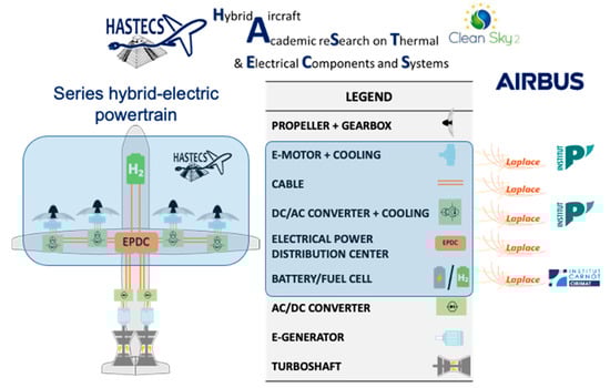
Figure 1.
The HASTECS project.
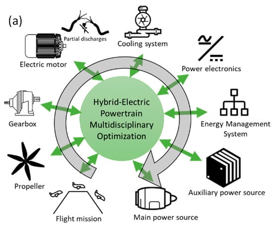
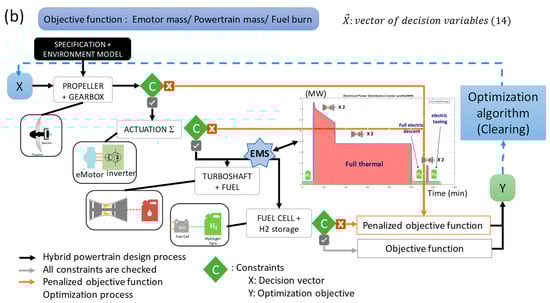
Figure 2.
Multidisciplinary design optimization of the hybrid electric powertrain: (a) the set of design models coupled in the MDO process; (b) the MDO process integrating environment.
One key objective of the HASTECS (Hybrid Aircraft reSearch on Thermal and Electrical Components and Systems) project was to integrate thermal and electrical issues within the hybrid electric aircraft powertrain by integrating the environmental constraints, in particular the partial discharges due to high voltages.
Several technological targets were focused on in the HASTECS project: a first level of assessments was dealing with the “target 2025” with specific powers higher than 5 kW/kg for electric motors and beyond 15 kW/kg for power electronics. A second level of assessments called “target 2035” was dealing with more ambitious assessments with electric motors with specific power higher than 10 kW/kg and power electronics beyond 25 kW/kg (both including the cooling devices). In the following, these two levels of targets will be considered with different levels of assessments for each device.
3. MDO-Oriented Modeling of the Hybrid Electric Powertrain
An in-depth technological study of the main components of the hybrid electric powertrain was carried out from the hybrid power sources (associating gas turbines as the main power source and batteries or fuel cells as auxiliary power sources) to electrically driven propellers.
3.1. Introduction to the MDO Process
The high part of Figure 2a illustrates the set of models integrated inside the MDO process coupling the different fields in a single global optimization problem. Each design-oriented technological model derives both device weight and losses (outputs) from design variables at the model input. Among the design variables, “decision variables” are the degrees of freedom exploited by the optimization algorithm: here, a mono objective meta heuristic based on genetic algorithm (i.e., the “Clearing” [49]) has been used to solve the MDO problem.
This MDO process couples:
- -
- requirements (flight mission: aircraft speed, altitude, thrust);
- -
- an environment model setting pressure and temperature variations over the flight mission;
- -
- a set of technological models constituting the integrated powertrain, each model identifying mass and efficiency of each component. As illustrated in Figure 2a, the powertrain design is addressed sequentially, starting from propulsion (thrust, speed) requirements specified over the flight mission, then crossing the powertrain models from downstream elements (propeller and gearbox) to upstream elements, i.e., the power sources (gas turbine and fuel cell) for which power is shared by the EMS. In the middle of the propulsion chain, the actuator part consisted of a voltage source inverter-fed permanent magnet synchronous motors (PMSM), which is really sensitive in terms of weight and efficiency;
- -
The MDO process is illustrated in Figure 2b:
- -
- As illustrated in the chart above, the hybrid electric powertrain design process progresses step by step, starting from downstream devices (propeller and gearbox), then assessing the actuation sub system (voltage inverter-fed electric motor) and completing the design with upstream (hybrid power sources) powertrain devices. Indeed, based on mission requirements specified by propulsion needs (i.e., aircraft thrust and speed), efficiencies of downstream elements progressively increase the power needs of upstream devices. In this manner, power sources (gas turbines and fuel cells) and storage (hydrogen tank and fuel mass) are finally designed in that process by operating an energy management strategy (EMS) that shares power flows between both sources over the flight mission;
- -
- A single objective function is derived by means of all technological model outputs. Several optimization formulations are compared in Section 4: a local one, only minimizing the electric motor (“Emotor”) mass, and two global optimization loops, minimizing the whole powertrain mass then the fuel burn. For each algorithm iteration, the clearing proposes a set of “decision variables” (X) which are set at the input of each design model;
- -
- These design models derive the set of constraints and participate to build the objective function. This latter (Y) is sometimes penalized if one of all constraints (C) is not fulfilled. As illustrated on the synoptic, a large set of design constraints related to all devices are progressively analyzed during the process. Some of them are a priori tested to assess the feasibility of the design to simulate the flight mission: for example, the stator winding feasibility of Emotors is a priori verified by taking account of partial discharge phenomena in the system environment (temperature, pressure) and regarding the voltage ratings. A second set of constraints is analyzed during the whole mission for each flight sequence. It is, for example, the case for thermal constraints in both power electronics and electric motors.
- -
- An EMS sharing the power between both sources is also operated during the virtual flight: thermal power source based on gas turbines (pink colored in the synoptic) vs. electric power source based on fuel cells (green colored in the synoptic).
3.2. Review of MDO-Oriented Technological Models
Each component has to be designed and integrated at the system level thanks to surrogate models to allow the MDO convergence with an acceptable computation cost. This part of the optimization problem is essential, and several complementary approaches are useful for that purpose:
- -
- Analytical models are to be used when possible, being often accurate with good convergence capabilities for optimization: in this study, power electronics as well as electromechanical and thermal cooling parts of electric motors are analytically derived. A particular modelling effort has been paid on that device which is the most sensitive component inside the powertrain regarding both weight and efficiency indicators. More details on sensitivity aspects can be found in [37].
- -
- Design models based on similarity laws [30] constitutes another efficient way to derive surrogate models: in our case study, the propeller design model exploits that approach by coupling analytical equations to derive the propeller efficiency with similarity laws to estimate its weight.
- -
- Finally, surface response-based models are often the solution when analytical derivation or similarity laws are impossible or too complex: in this study, it has been the case for several studies such as gas turbines and gearbox.
- -
- All model details cannot be provided in this paper and only some major aspects are summarized and referenced in the next sub section, starting from downstream (propeller) and going to upstream (hybrid power sources) powertrain devices.
3.2.1. Modelling of Propulsion Devices
First, a “performance model” is derived to estimate the propeller efficiency (ηprop) during the flight (see Figure 3): given the aircraft thrust (TA/C) and speed (VA/C) specified by requirements over the flight mission, the disk actuator theory allows us to analytically derive the mechanical power (Pshaft) of the propeller shaft and its efficiency. The “sizing model” allows us to assess, in particular, the propeller mass (Mprop). This estimation is based on a similarity law (scaling model) referenced from the design of the existing propeller related to the ATR72 aircraft from which the propeller mass versus diameter ratio is known. Input/output variables are displayed in Table 1, and more details on that surrogate model are proposed in [8,35]
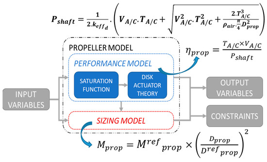
Figure 3.
Analytical (performance) and scaling (sizing) model for propeller design.

Table 1.
Input/output variables for propeller model (in bold, the decision variables for optimization).
Then, a parametric linear regression (surface response model) used in [17] sizes the gearbox weight. The shaft power (Pshaft), the propeller rotation speed (RPMout) and the gearbox ratio (RPMin/RPMout) are the input data for this model (see Figure 4).
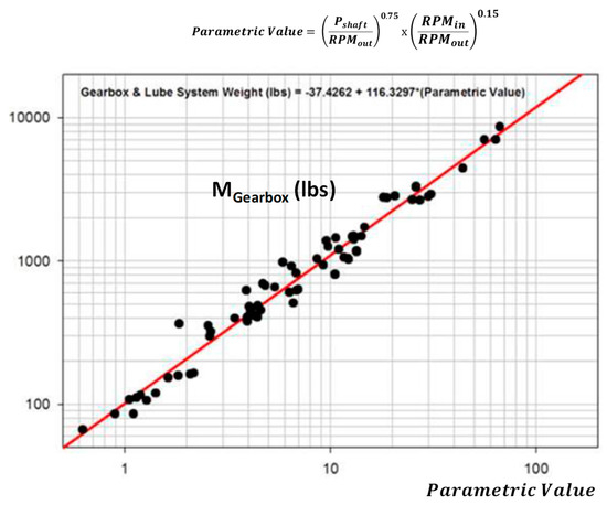
Figure 4.
Regression model for gearbox weight assessment (see [17]).
3.2.2. Modelling of the Electric Motor (Emotor)
Upstream of the gearbox, the electromechanical actuator design model detailed in [35,36] has been achieved through an analytical model. The Emotor is a surface-mounted permanent magnet synchronous motor (SM-PMSM) combining high efficiency and specific power. In order to optimize the Emotor integration, several technological choices have been made, among them a PM Halbach segmented array with high-temperature tolerant (SmCo) magnets. Ultra-thin magnetic sheets are used to lower the iron losses together with twisted Litz wires to reduce AC Joule losses that can be huge for high-speed motors. The complete design with detailed choices that have been made during HASTECS are referenced in [40,41].
From a set of geometrical decision variables (see the Table 2), electric circuit parameters are determined in order to compute the different losses of the electric machine over the flight mission (see Figure 5). Furthermore, a set of constraints are considered in the optimization problem formulation. For example, mechanical constraint equations related to the maximum centrifugal pressure and the maximum peripheral speed are set in order to design the right carbon sleeve thickness. Partial discharge (stator winding feasibility) and thermal constraints are described below. The mechanical feasibility must also be verified: a control strategy with field weakening is operated for each mechanical point (torque speed plan) of the flight mission. More details on the motor design and on constraint derivation can be found in [40,41].
Table 2.
Input/output variables for Emotor model.
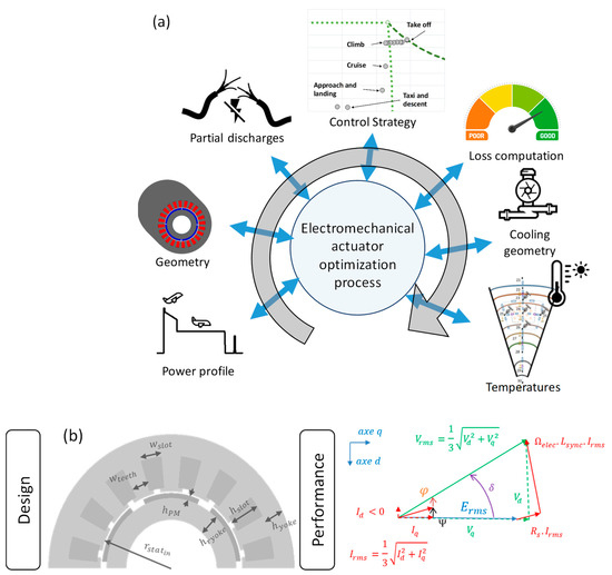
Figure 5.
Analytical multifaceted model (a) with geometry, (b) design and performance of Emotor (PMSM).
Once the losses are computed and the electric motor geometry is set, an analytical thermal model permits to evaluate the temperature nodes inside the electric motor along the flight mission. Numerous design constraints drive the actuation system optimization but the most sensitive is certainly the motor temperature limits.
The cooling system (see Figure 6) is composed of a glycol water jacket for the external cooling of the stator and a rotor shaft cooling: it constitutes the first level of assessments dealing with the “target 2025”. In order to increase the integration performance, a second level of assessment, so called “target 2035”, also involves an internal cooling system directly inside stator slots in addition to the previous cooling channels. The description of the cooling system is detailed in [38,39].
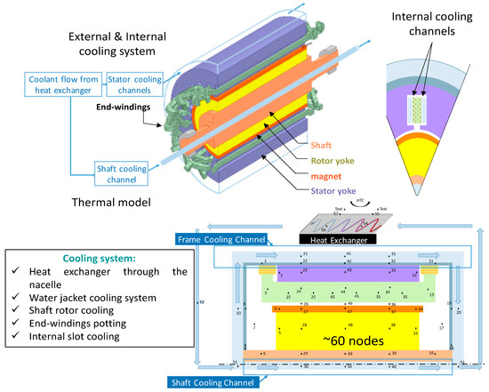
Figure 6.
3D plot of the electric motor and its integrated cooling system.
Due to the high level of voltages (HVDC bus voltage beyond 1 kV), the issue of partial discharges (PD) was also addressed and integrated into the MDO process. Indeed, high voltage bus can be a solution to decrease weights (typically that of the cables) but this voltage increase generally involves the appearance of partial discharges that may reduce the lifespan of motor windings especially at low pressure conditions as detailed in [42,50,51,52]. Based on that complete study, a meta-model has been built to simply verify the feasibility constraint related to windings. This surrogate model for partial discharge constraints is integrated in the motor design model and permits a system-oriented optimization of the actuation device [36] (see Figure 7). Two different issues have been considered:
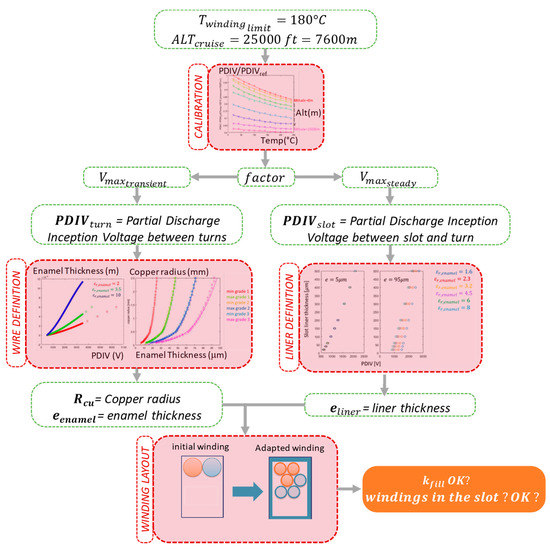
Figure 7.
Process for PD-tolerant stator winding adaptation.
- -
- First, the turn-to-turn voltage is assessed depending on the power electronics structure. The PDIV (partial discharge inception voltage) is then derived, taking account of temperature and pressure (altitude) conditions. Then, the insulation thickness is calculated together with insulation material choices [43];
- -
- Second, the liner (bottom of the slots) thickness is estimated from the maximum voltage between turns and yoke.
In both cases, polynomial approximations are used to complete the surrogate model.
Finally, an adapted winding involving PD tolerance is derived fulfilling a filling factor constraint. Readers may find details on that model in [35,36].
3.2.3. Modelling of Power Electronics with Its Thermal Cooling
In addition to the actuation system modelling involving main couplings with thermal and partial discharges aspects, a high-power density inverter has also been performed as detailed in [44,45]. To combine very high-power densities and high efficiencies, two multilevel conversion structures have been chosen with optimized (minimal switching losses) control strategies: three-level NPC (neutral point clamped) and five-level ANPC (active NPC) structures have been selected depending on the bus voltage level (see Figure 8). An analytical model evaluates the performance (estimated losses and weights) of the inverter, given the semiconductor choices, the architecture and the control strategy (see the input/output variables in Table 3). Selecting IGBTs permits performance increase with efficiencies in the order of 99%. Indeed, regarding the particular requirements of this series architecture for hybrid electric aircraft, the 7th generation of IGBTs (1200 V or 1700 V rated) have been preferred to wide band gap (SiC or GaN) power devices: this is firstly due to the low influence of switching losses with specific modulation strategy which remains limited with respect to the conduction losses. Secondly, wide band gap devices involve high frequency switchings which may induce overvoltages in cables and stator windings. These phenomena consequently provoke the worsening of partial discharges inside these system elements. These electric insulation issues have been assessed in the design tool of [42,43].
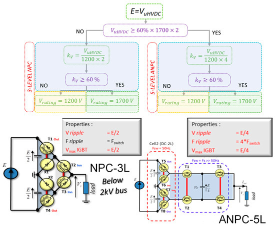
Figure 8.
Analytical model of power inverter structures.
Table 3.
Input/output variables for power electronic (inverter) model.
However, the huge integration of such a power module also brings severe thermal constraints. The study conducted in [46,47] highlights a very high-performance two-phase cooling subsystem (see Figure 9): the capillary-pumped cooling system optimization allows the power module to evacuate 4.5 kW/kg in thermal losses! A parametric linear regression is used as a surrogate model. It allows the “system designer” to simply size the total mass of the cooling system from the maximum value of the inverter losses to be evacuated (see Figure 10), given the level of technological performance (here, assessments are related to the “target 2035” detailed in [46]).
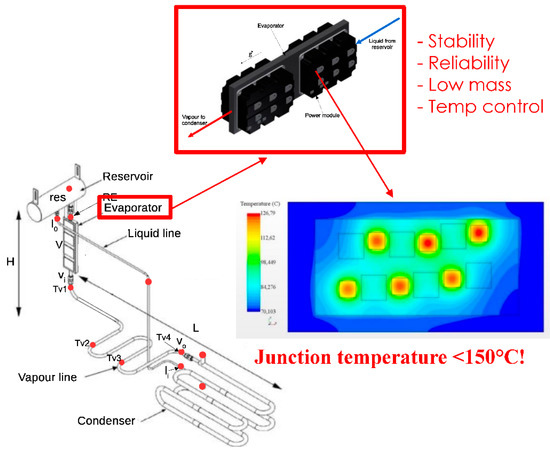
Figure 9.
Power module and its two-phase cooling system.
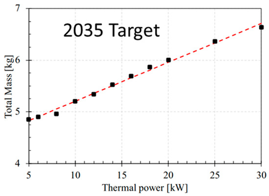
Figure 10.
Cooling system mass evaluation versus maximum thermal losses.
3.2.4. Modelling of Hybrid Power Sources
The modeling of the hybrid electric powertrain continues with the design of both power sources. The power sharing between thermal (gas turbines) and electric sources (fuel cells or batteries) is directly the consequence of the energy management strategy (EMS). A “simple hybridization scenario” is illustrated in Section 4.1: in that case, very simple management rules are set, by preferring full electric power during low-power operation (taxi and descent phase) for which the efficiency of gas turbines are quite low. Oppositely, thermal sources are preferred during high-power operation, in particular during climb and cruise.
A state of the art has been carried out about candidate electrochemical sources in the HASTECS context (requirements) and by considering that “simple hybridization scenario” of EMS [48]: lithium-ion batteries vs. low-temperature proton-exchange membrane fuel cell (PEMFC). This prospective study has identified the most suitable technologies for hybridizing the aircraft propulsion. For the “simple hybridization scenario”, a priori setting taxi and descent phases in full electric mode, the power-energy requirements are simply synthesized as illustrated in Figure 11 with a maximum electric power demand of 280 kW and 157 kWh of electric energy required to complete the mission.
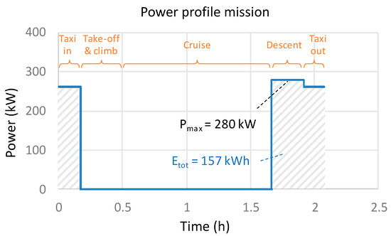
Figure 11.
Simple hybridization scenario, a priori setting the hybrid ratio.
In Figure 12, based on the particular power energy requirements illustrated above, the auxiliary electric system mass of batteries especially oriented for power (LTO) and energy (NMC and LiS) constraints are compared with the total mass given by PEMFC (stack and balance of plant) with high-pressure (700 bar) H2 or liquid cryogenic (20°K) H2 storage. Given the mission, the mass tradeoff is quite obvious: the PEMFC with its H2 liquid storage is the best candidate to hybridize the propulsion of “this” series hybrid regional aircraft. In the following work, fuel cells with cryogenic storage system at 20°K will be considered.
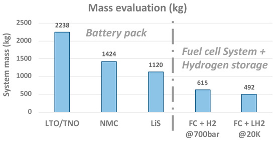
Figure 12.
Mass evaluation given the mission.
A hybridization ratio distributes the power between both the turboshaft and fuel cell, estimating energy consumption of each. Thus, to complete the powertrain model, a cartography (see Figure 13) is defined for the gas turbine [8] in order to easily integrate it into the MDO process. This model derives the specific fuel consumption (SFC) versus the maximum (takeoff) power with reference to a database extracted from civil and military turboshafts:
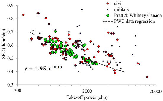
Figure 13.
Parametric regression of the turboshaft design model; SFC is the ratio between weight and the energy fed by the gas turbine.
4. Multidisciplinary Design Optimization of the HASTECS Hybrid Electric Powertrain
Once all the powertrain devices are modelled, an implicit loop typical of a “snowball effect” has to estimate the required thrust for the aircraft to take off according to the embedded weight variations. The snowball effect is due to the fact that: the higher the embedded weight, the larger the structure (wing surface) and, consequently, the higher the fuel burn, with more fuel weight also meaning more embedded weight. In most aircraft conceptual design studies [4,25,28], variable embedded weights are coupled with aerodynamic structure (wing surface with subsequent drag penalties) and engine needs in a global MDO processed at aircraft level. However, by means of the technological models previously described, computation means are actually not sufficient to be coupled with aerodynamic and propulsion aspects, and this coupling must be simplified. In that context, as illustrated in Figure 14, weight variations during MDO convergence in sized devices induce variations of the aircraft maximum takeoff weight (MTOW), which is derived from unit weights. These MTOW variations involve variable thrust needs. In our case, the problem has been simplified by linearizing the relationship between variations of global mass (MTOW) and the required thrusts:
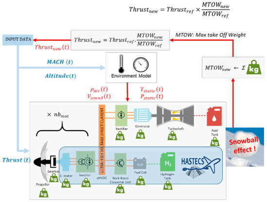
Figure 14.
Integrated design of the aircraft powertrain involving snowball effect.
This simplified approach is partly justified by a constant lift-to-drag ratio hypothesis at cruise and has been validated in [35] (for a limited mass range) by comparison between this linear model and complete aerodynamic models detailed in [8].
Finally, during the convergence of the powertrain optimization, propulsive demand (thrust) varies, and every device is sized consequently from downstream element (propeller, gearbox) to upstream power sources (fuel cells, storage, gas turbine, fuel tank). For each upstream element, losses in the downstream device induce additional power demand with consequences on its weight.
4.1. Integrated Design of A Hybrid Electric Aircraft with a “Simple Hybridization Scenario”
In order to complete the MDO process, a hybridization scenario for the energy management system (EMS) has to be implemented to set the hybridization ratio which shares both powers for thermal and auxiliary electric sources.
A “simple hybridization scenario” is firstly assessed, setting a priori the hybridization ratio between both sources as illustrated on the Figure 15. This simple EMS allows us to simply focus on the powertrain design: in that scenario, the taxi and descent phases are a priori electrically supplied fully by the PEMFC while gas turbines completely provide the other flight phases (takeoff, climb, cruise).
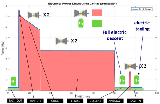
Figure 15.
Example of power sharing (simple EMS) between thermal engines and PEMFC.
Regarding the powertrain MDO, three mathematical formulations have been considered according to the process described in Figure 2b [35]:
- (1)
- A “local optimization” only minimizing the electric motor mass;
- (2)
- A “powertrain optimization” minimizing its whole mass;
- (3)
- A “fuel burn optimization”.
The “local optimization” only minimizes the mass of the electric machine including the cooling system: results of this local optimization are detailed in [36]. All the other powertrain components are sized according to the evolution of the system efficiency, and this optimization takes the snowball effect into account. At the end of the local optimization, an optimal electric motor mass is found checking the optimization constraints. The second formulation is quite the same but focuses on the total powertrain mass minimization. The ecological point of view is chosen on the third formulation, minimizing the aircraft fuel burn. Fourteen decision variables (1 for the snowball effect, 1 for the propeller, 1 for the gearbox, 10 for the electric motor, 1 for power electronics) are required to size the powertrain given the simple EMS (see Table 4). Note that particular attention has been paid to the electric motor design as it has been seen as the most sensitive device on system objectives [37].
Table 4.
Decision variables for MDO with variation ranges.
Furthermore, 15 feasibility constraints were integrated: these latter are detailed in [35]. These constraints are mainly related to the electric motor and its cooling, including the partial discharges (feasibility of stator windings) and the motor-power electronics association (frequency compatibility). A supplementary constraint has been added at the aircraft level to integrate the snowball effect. This MDO process is illustrated in Figure 16.
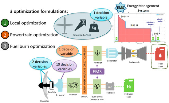
Figure 16.
Different formulations for the MDO of the powertrain.
The clearing procedure [49] was used for optimizing the propulsion system of the hybrid aircraft. The “clearing” is a genetic algorithm based on “niching elitist” which usually outperforms standard genetic algorithms on difficult problems with multiple non-linear constraints and multimodal features [53]. All constraints were normalized and integrated into the objective function by adding penalty coefficients. The population size and the number of generations were respectively set to 100 and 200. Classical values for crossover and mutation rates were used (i.e., pc = 1 and pm = 1%). Due to the stochastic nature of the clearing algorithm, multiple runs were repeated for each optimization case. It contributes to increase the reproducibility of results. The CPU time required for solving each optimization case on a standard computer was about seven days.
First, the optimal aircraft solution in terms of kerosene consumption has been logically found with the “fuel burn optimization” for which consumption is 3% lower than the one offered by the “local optimization” (see Figure 17a). However, it should be noted that the formulation for “fuel burn optimization” involves a powertrain mass slightly increased (see Figure 17b). In fact, as illustrated on the Figure 17e, the propeller diameter is oversized in order to maximize the propeller (consequently the powertrain) efficiency (see Figure 17d): indeed, the powertrain efficiency is increased by 1.5% to 6% depending on the flight sequence regarding the “fuel burn optimization” with respect to the “local optimization”. The efficiency improvement of the propeller (downstream in the powertrain) reduces the maximum values of the design powers for the other upstream components, consequently reducing the kerosene consumption. This systemic effect is clearly a typical result, which highlights the interest of such an MDO process involving main system couplings.
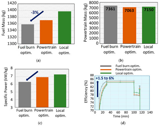
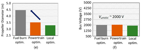
Figure 17.
Comparison of optimization results for three MDO formulations. (a) Fuel mass; (b) powertrain mass; (c) Emotor specific power; (d) powertrain efficiency; (e) propeller diameter; (f) UHVDC voltage.
On the opposite side, it is not surprising to notice that the formulation with a “local optimization” induces the highest specific power for the electric motor (see Figure 17c).
Let us note that all results presented in that section have been obtained with the assessments corresponding with the “target 2025”, especially without the direct stator cooling inside slots. As detailed in [36], adding internal cooling allows an increase in motor specific powers from 6 kW/kg to 11 kW/kg.
Finally, this MDO process couples a set of domains (power electronics, electric machine and cooling, partial discharges, mechanical transmission and propelling) leading to an optimal bus voltage range of around 2 kV, which constitutes the best trade-off in this case study (see Figure 17f).
4.2. Integrated Design of a Hybrid Electric Aircraft with an Optimal Hybridization Scenario
Going further with the overall integrated design of the aircraft powertrain, the EMS has been integrated into the optimization process. The previous results obtained with the “simple hybridization scenario” constitute a reference “a priori” setting the hybridization ratio (HR): . An HR equals to 1 means that the power is fully supplied by the electric source when a null HR is equivalent to provide full thermal power. These HRs are now integrated during the flight mission as supplementary decision variables in the overall MDO process. This results in adding 12 supplementary variables into the optimization formulation, increasing its complexity (i.e., a total of 26 decision variables instead of 14 in the three previous optimization cases) and requiring 14 days of computation on a standard computer. Figure 18 illustrates the comparison between both EMS operations. Comparing both EMS, the “optimized HR” hybridization scenario leads to a huge increase of the fuel cell nominal power (the PEMFC system mass is multiplied by ~4 with respect to the previous simple EMS) in order to use the fuel cell during the whole mission, even during climb and cruise. However, this power management reduces the fuel burn by 15%. Regarding the “ecological” point of view (burn of kerosene), the “optimized EMS” is the best solution, but it is clearly paid regarding the MTOW. Thus, Figure 19 compares different solutions and assessments (“Targets”) in the fuel burn vs. MTOW plan: it displays the relative variations with reference to a full thermal aircraft optimized with the same models but without electric hybridization. Two different levels of assessments (2025 vs. 2035 targets) are compared: the differences between those two targets are detailed in [35], but the main one is related to the performance of cooling devices for power electronics and electric motor; for the latter, a direct cooling inside stator slot is added.
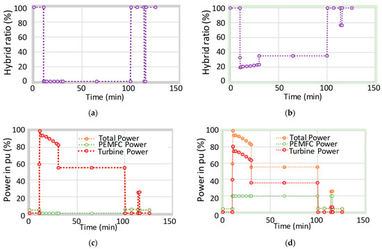
Figure 18.
Energy management system (EMS) optimization. (a) Hybrid ratio with the simple EMS; (b) Hybrid ratio with the optimized EMS; (c) Power sharing with the simple EMS; (d) Power sharing with the optimized EMS.
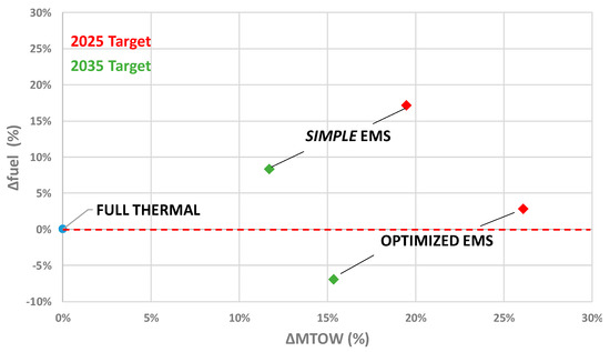
Figure 19.
Hybrid electric aircraft with a conventional aircraft as a reference point.
This display clearly shows a major issue: “despite the technological progress, electric hybrid solutions are heavier than thermal solutions”. Regarding the EMS influence, the increase of the fuel cell nominal power decreases the fuel burn but is not without consequences on the MTOW, which has been increased by 4–7% according to the assessment target.
Finally, with reference to a full thermal optimized aircraft, an “optimized EMS” allows the operation of a hybrid aircraft that may consume the same amount of kerosene for the 2025 target. By improving the technology (i.e., increasing specific powers), the “HASTECS 2035 hybrid electric aircraft” would consume 6% less fuel than its full-thermal equivalent.
Let us finally note that only the consequences of energy efficiency and powertrain weight have been assessed in this study as a unique influence on the fuel burn. Going towards aerodynamic optimization, especially by means of distributed electric propulsion architectures, may offer additional gains in terms of aerodynamics with several innovative concepts such as blown wing, boundary layer ingestion or wing tip propellers [8,9,10,11].
5. Conclusions and Prospects
In this paper, an MDO process applied for the series hybrid regional aircraft has been proposed focusing on the main devices of the hybrid powertrain. A complete set of adapted surrogate models have been integrated to face the complexity of that integration process also involving typical snowball effects in aircrafts. These technological design models allow the integration of main disciplinary aspects (electrical, mechanical, thermal, EMS) and environmental constraints (partial discharges, flight mission), which are coupled in the MDO. Several mathematical formulations have been proposed comparing local with systemic optimizations. Typical coupling effects have emerged by integrating all devices in this MDO process, showing that a heavier but more efficient powertrain may lead to fuel burn reduction.
Coupled with the powertrain optimization, integrating non-propulsive electric loads such as the air conditioning will be another advantage of more electric aircrafts and should be a prospect for future studies.
However, as shown in this paper, fuel burn gains remain limited as hybrid electric aircrafts are generally heavier than thermal ones. In that context, it seems that the “actual breakthrough” may be the zero-emission aircraft as recently announced by Airbus. The hydrogen solution (if it is burnt in thermal engines or converted in fuel cells with all-electric chains) seems to be a clear research direction in the air sector, from short-range (regional) flights to medium- to long-distance flights.
NASA [54] and Airbus [55] claim innovative prospects in that direction, for example, by coupling cryogenic liquid hydrogen with superconducting components.
A very simplified prospect analysis has been performed in HASTECS with the models described in that paper in order to evaluate the performance of a hydrogen–electric-powered aircraft. The same MDO process has been used and two assessment levels have been launched for 2025 and 2035 targets. In addition to the assumptions made for the motors and inverters, aggressive assessments have been set for the fuel cell system and its hydrogen storage (see Table 5). These targets are firstly related to a power density of the fuel cell system integrating its balance of plant with all auxiliaries except the primary heat exchanger. Secondly, assumptions on the hydrogen mass ratio in the storage tank are respectively assessed to 20 and 25%. The aircraft architecture is based on a four-engine propulsion, each nacelle being a stand-alone (POD) propeller propulsion system powered by hydrogen fuel cells. These prospective results highlight the main issue of hybrid electric or full electric aircrafts: the powertrain mass is significantly increased with reference to a full-thermal optimized aircraft. The “target 2025” MTOW rises by 150% and “target 2035” by 125% (see Figure 20). Without surprise, the heaviest element in the propulsion chain is the fuel cell system with its hydrogen storage.
Table 5.
Technological targets of H2 systems (see [48]).
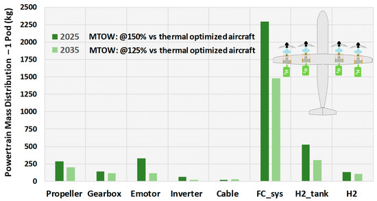
Figure 20.
Exploratory study of a four-engine hydrogen–electric powered aircraft.
The future the zero-emission aircraft has then to be more deeply studied, even if huge technological and safety (certification) challenges are in front of engineers, being a major track towards greener aircrafts!
Author Contributions
The main contribution was done during M.P.-D.’s PHD Thesis which was co-directed by X.R. and B.S., X.R. has coordinated the HASTECS EU project. All authors have read and agreed to the published version of the manuscript.
Funding
This research was funded by European Union’s Horizon 2020 (Clean Sky 2 JTI) research and innovation program (2014–2024), under grant agreement No. 715483.
Data Availability Statement
Main data may be found in HASTECS book (see [48]).
Acknowledgments
The HASTECS project has received funding from the European Union’s Horizon 2020 (Clean Sky 2 JTI) research and innovation program (2014–2024), under grant agreement No. 715483.
Conflicts of Interest
The authors declare no conflict of interest.
References
- IATA. “Technology Roadmap to 2050,” International Air Transport Association. 2013. Available online: https://www.iata.org/contentassets/8d19e716636a47c184e7221c77563c93/Technology-roadmap-2050.pdf (accessed on 1 September 2022).
- Sarlioglu, B.; Morris, C.T. More Electric Aircraft: Review, Challenges, and Opportunities for Commercial Transport Aircraft. IEEE Trans. Transp. Electrif. 2015, 1, 54–64. [Google Scholar] [CrossRef]
- Berger, R. Electric Propulsion Is Finally on the Map. Available online: https://www.rolandberger.com/en/Insights/Publications/Electric-propulsion-is-finally-on-the-map.html (accessed on 18 March 2020).
- Pornet, C.; Isikveren, A. Conceptual design of hybrid-electric transport aircraft. Prog. Aerosp. Sci. 2015, 79, 114–135. [Google Scholar] [CrossRef]
- Epstein, A.H.; O’Flarity, S.M. Considerations for Reducing Aviation’s CO2 with Aircraft Electric Propulsion. J. Propuls. Power 2019, 35, 572–582. [Google Scholar] [CrossRef]
- Ansell, P.J.; Haran, K.S. Electrified Airplanes: A Path to Zero-Emission Air Travel. IEEE Electrif. Mag. 2020, 8, 18–26. [Google Scholar] [CrossRef]
- Madonna, V.; Giangrande, P.; Galea, M. Electrical Power Generation in Aircraft: Review, Challenges, and Opportunities. IEEE Trans. Transp. Electrif. 2018, 4, 646–659. [Google Scholar] [CrossRef]
- Thauvin, J. Exploring the Design Space for a Hybrid-Electric Regional Aircraft with Multidisciplinary Design Optimisation Methods. Ph.D. Thesis, Institut National Polytechnique de Toulouse (Toulouse INP), Toulouse, France, 2018. Available online: https://oatao.univ-toulouse.fr/23607/1/Thauvin_jerome.pdf (accessed on 1 September 2022).
- Clarke, S.; Redifer, M.; Papathakis, K.; Samuel, A.; Foster, T. X-57 Power and Command System Design. In Proceedings of the 2017 IEEE Transportation Electrification Conference and Expo (ITEC), Chicago, IL, USA, 22–24 June 2017; pp. 393–400. [Google Scholar] [CrossRef]
- Hermetz, J.; Ridel, M.; Doll, C. Distributed electric propulsion for small business aircraft a concept-plane for key-technologies investigations. In Proceedings of the 30th Congress of the International Council of the Aeronautical Sciences, Deajeon, Korea, 25–30 September 2016; pp. 1–10. [Google Scholar]
- Dillinger, E.; Döll, C.; Liaboeuf, R.; Toussaint, C.; Hermetz, J.; Verbeke, C.; Ridel, M. Handling qualities of ONERA’s small business concept plane with distributed electric propulsion. In Proceedings of the 30th Congress of the International Council of the Aeronautical Sciences, Belo Horizonte, Brazil, 9–14 September 2018; pp. 1–10. [Google Scholar]
- Gao, Y.; Yang, T.; Bozhko, S.; Wheeler, P.; Dragicevic, T. Filter Design and Optimization of Electromechanical Actuation Systems Using Search and Surrogate Algorithms for More-Electric Aircraft Applications. IEEE Trans. Transp. Electrif. 2020, 6, 1434–1447. [Google Scholar] [CrossRef]
- Zhang, X.; Bowman, C.L.; O'Connell, T.C.; Haran, K.S. Large electric machines for aircraft electric propulsion. IET Electr. Power Appl. 2018, 12, 767–779. [Google Scholar] [CrossRef]
- Donateo, T.; De Pascalis, C.L.; Ficarella, A. Synergy Effects in Electric and Hybrid Electric Aircraft. Aerospace 2019, 6, 32. [Google Scholar] [CrossRef]
- Glassock, R.; Galea, M.; Williams, W.; Glesk, T. Hybrid Electric Aircraft Propulsion Case Study for Skydiving Mission. Aerospace 2017, 4, 45. [Google Scholar] [CrossRef]
- Brown, G.V. Weights and efficiencies of electric components of a turboelectric aircraft propulsion system. In Proceedings of the 49th AIAA Aerospace Sciences Meeting Including the New Horizons Forum and Aerospace Exposition, Orlando, FL, USA, 4–7 January 2011. [Google Scholar] [CrossRef]
- Antcliff, K.R.; Guynn, M.D.; Marien, T.; Wells, D.P.; Schneider, S.J.; Tong, M.J. Mission Analysis and Aircraft Sizing of a Hybrid-Electric Regional Aircraft. In Proceedings of the 54th AIAA Aerospace Sciences Meeting, San Diego, CA, USA, 4–6 January 2016; pp. 1–18. [Google Scholar] [CrossRef]
- Voskuijl, M.; Van Bogaert, J.; Rao, A.G. Analysis and design of hybrid electric regional turboprop aircraft. CEAS Aeronaut. J. 2018, 9, 15–25. [Google Scholar] [CrossRef]
- Ye, X.I.E.; Savvarisal, A.; Tsourdos, A.; Zhang, D.; Jason, G.U. Review of hybrid electric powered aircraft, its conceptual design and energy management methodologies. Chin. J. Aeronaut. 2021, 34, 432–450. [Google Scholar]
- Ribeiro, J.; Afonso, F.; Ribeiro, I.; Ferreira, B.; Policarpo, H.; Peças, P.; Lau, F. Environmental assessment of hybrid-electric propulsion in conceptual aircraft design. J. Clean. Prod. 2020, 247, 119477. [Google Scholar] [CrossRef]
- Rings, R.; Ludowicy, J.; Finger, D.F.; Braun, C. Sizing Studies of Light Aircraft with Parallel Hybrid Propulsion Systems; Deutsche Gesellschaft für Luft-und Raumfahrt-Lilienthal-Oberth eV,: Bonn, Germany, 2018. [Google Scholar] [CrossRef]
- Brelje, B.J.; Martins, J.R. Electric, hybrid, and turboelectric fixed-wing aircraft: A review of concepts, models, and design approaches. Prog. Aerosp. Sci. 2018, 104, 1–19. [Google Scholar] [CrossRef]
- Janovec, M.; Čerňan, J.; Škultéty, F.; Novák, A. Design of batteries for a hybrid propulsion system of a training aircraft. Energies 2021, 15, 49. [Google Scholar] [CrossRef]
- Saias, C.A.; Goulos, I.; Roumeliotis, I.; Pachidis, V.; Bacic, M. Preliminary Design of Hybrid-Electric Propulsion Systems for Emerging Urban Air Mobility Rotorcraft Architectures. J. Eng. Gas Turbines Power 2021, 143, 111015. [Google Scholar] [CrossRef]
- Hoelzen, J.; Liu, Y.; Bensmann, B.; Winnefeld, C.; Elham, A.; Friedrichs, J.; Hanke-Rauschenbach, R. Conceptual Design of Operation Strategies for Hybrid Electric Aircraft. Energies 2018, 11, 217. [Google Scholar] [CrossRef]
- Martins, J.; Lambe, A.B. Multidisciplinary Design Optimization: A Survey of Architectures. AIAA J. 2013, 51, 2049–2075. [Google Scholar] [CrossRef] [Green Version]
- Iwaniuk, A.; Wiśniowski, W.; Żółtak, J. Multi-disciplinary optimisation approach for a light turboprop aircraft-engine integration and improvement. Aircr. Eng. Aerosp. Technol. 2016, 88, 348–355. [Google Scholar] [CrossRef]
- Lefebvre, T.; Schmollgruber, P.; Blondeau, C.; Carrier, G. Aircraft conceptual design in a multilevel, multifidelity, multidisciplinary optimization process. In Proceedings of the 28th International Congress of The Aeronautical Sciences, Brisbane, Australia, 28th September 2012; pp. 23–28. [Google Scholar]
- Gazaix, A.; Gallard, F.; Gachelin, V.; Druot, T.; Grihon, S.; Ambert, V.; Guénot, D.; Lafage, R.; Vanaret, C.; Pauwels, B.; et al. Towards the Industrialization of New MDO Methodologies and Tools for Aircraft Design. In Proceedings of the AIAA/ISSMO (18th Multidisciplinary Analysis and Optimization Conference—The American Institute of Aeronautics and Astronautics), Denver, CO, USA, 5–9 June 2017; pp. 1–23. [Google Scholar]
- Delbecq, S.; Budinger, M.; Ochotorena, A.; Reysset, A.; Defay, F. Efficient sizing and optimization of multirotor drones based on scaling laws and similarity models. Aerosp. Sci. Technol. 2020, 102, 105873. [Google Scholar] [CrossRef]
- De Giorgi, F.; Budinger, M.; Hazyuk, I.; Reysset, A.; Sanchez, F. Reusable Surrogate Models for the Preliminary Design of Aircraft Application Systems. AIAA J. 2021, 59, 2490–2502. [Google Scholar] [CrossRef]
- Liu, Y.; Elham, A.; Horst, P.; Hepperle, M. Exploring Vehicle Level Benefits of Revolutionary Technology Progress via Aircraft Design and Optimization. Energies 2018, 11, 166. [Google Scholar] [CrossRef]
- Brelje, B. Multidisciplinary Design Optimization of Electric Aircraft Considering Systems Modeling and Packaging. Doctoral Dissertation, Aerospace Engineering and Scientific Computing, University of Michigan, Ann Arbor, MI, USA, 2021. [Google Scholar]
- Finger, D.F. Methodology for Multidisciplinary Aircraft Design under Consideration of Hybrid-Electric Propulsion Technology. Doctoral Dissertation, RMIT University, Melbourne, VIC, USA, 2020. [Google Scholar]
- Pettes-Duler, M. Integrated Optimal Design of a Hybrid-electric Aircraft Powertrain. Ph.D. Thesis, Institut National Polytechnique de Toulouse (Toulouse INP), Toulouse, France, 2021. Available online: https://oatao.univ-toulouse.fr/28350/1/Pettes_Duler_Matthieu_.pdf (accessed on 1 September 2022).
- Pettes-Duler, M.; Roboam, X.; Sareni, B.; Lefevre, Y.; Llibre, J.-F.; Fénot, M. Multidisciplinary Design Optimization of the Actuation System of a Hybrid Electric Aircraft Powertrain. Electronics 2021, 10, 1297. [Google Scholar] [CrossRef]
- Pettes-Duler, M.; Roboam, X.; Sareni, B. Integrated Design Process and Sensitivity Analysis of a Hybrid Electric Propulsion System for Future Aircraft. In Lecture Notes in Electrical Engineering; Springer: Berlin/Heidelberg, Germany, 2020; Volume 1, pp. 71–85. [Google Scholar]
- Zeaiter, A. Thermal Modeling and Cooling of Electric Motors Application to the Propulsion of Hybrid Aircraft. Ph.D. Thesis, Ecole Nationale Supérieure de Mécanique et d’Aérotechnique (ENSMA), Chasseneuil-du-Poitou, France, 2020. Available online: https://tel.archives-ouvertes.fr/tel-03158868/document (accessed on 1 September 2022).
- Zeaiter, A.; Fenot, M. Thermal Sensitivity Analysis of a High Power Density Electric Motor for Aeronautical Application. In Proceedings of the 2018 IEEE International Conference on Electrical Systems for Aircraft, Railway, Ship Propulsion and Road Vehicles International Transportation Electrification Conference (ESARS-ITEC), Nottingham, UK, 7–9 November 2018; pp. 1–6. [Google Scholar] [CrossRef]
- Touhami, S. Analytical Sizing Models to Assess the Performances of High Specific Power Electric Motors for Hybrid Aircraft. Ph.D. Thesis, Institut National Polytechnique de Toulouse (Toulouse INP), Toulouse, France, 2020. Available online: https://oatao.univ-toulouse.fr/28218/1/Touhami_Sarah.pdf (accessed on 1 September 2022).
- Touhami, S.; Zeaiter, A.; Fenot, M.; Lefèvre, Y.; Llibre, J.F.; Videcoq, E. Electrothermal models and design approach for high specific power electric motor for hybrid aircraft. In Proceedings of the Aerospace Europe Conference, Bordeaux, France, 25–28 February 2020. [Google Scholar]
- Collin, P. Design, Taking into Account the Partial Discharges Phenomena, of the Electrical Insulation System (EIS) of High Power Electrical Motors for Hybrid Electric Propulsion of Future Regional Aircrafts. Ph.D. Thesis, Université de Toulouse, Toulouse, France, 2020. Available online: http://thesesups.ups-tlse.fr/4730/1/2020TOU30116.pdf (accessed on 1 September 2022).
- Collin, P.; Malec, D.; Lefèvre, Y. Tool to predict and avoid Partial Discharges in stator slot of rotating motors fed by inverter. In Proceedings of the Aerospace Europe Conference, Bordeaux, France, 25–28 February 2020. [Google Scholar]
- Erroui, N. Chaine de Conversion Forte Puissance Pour la Propulsion Aéronautique Hybride. Ph.D. Thesis, Toulouse INP, Toulouse, France, 2019. Available online: https://oatao.univ-toulouse.fr/25529/1/Erroui_najoua.pdf (accessed on 1 September 2022).
- Erroui, N.; Gateau, G.; Roux, N. Continuous-caliber semiconductor components. In Proceedings of the 2018 IEEE International Conference on Industrial Technology (ICIT), Lyon, France, 20–22 February 2018. [Google Scholar]
- Accorinti, F. Two-Phase Power Electronics Cooling Solution Design in Air Context Answer to the Objectives of the Hybrid Aircraft 2035. Ph.D. Thesis, Ecole Nationale Supérieure de Mécanique et d’Aérotechnique (ENSMA), Chasseneuil-du-Poitou, France, 2020. Available online: https://tel.archives-ouvertes.fr/tel-02993195/document (accessed on 1 September 2022).
- Accorinti, F.; Erroui, N.; Ayel, V.; Gateau, G.; Bertin, Y.; Roux, N.; Dutour, S.; Miscevic, M. High-efficiency cooling system for highly integrated power electronics for hybrid propulsion aircraft. In Proceedings of the 2019 IEEE 28th International Symposium on Industrial Electronics (ISIE), Vancouver, BC, Canada, 12–14 June 2019; pp. 870–877. [Google Scholar]
- Roboam, X.; Al. The HASTECS Book (Hastecs: Hybrid Aircraft: Research on Thermal and Electric Components and Systems), 27 October 2021. Available online: https://hal-univ-tlse3.archives-ouvertes.fr/hal-03407214 (accessed on 1 September 2022).
- Petrowski, A. A clearing procedure as a niching method for genetic algorithms. In Proceedings of the IEEE International Conference on Evolutionary Computation, Nagoya, Japan, 20–22 May 1996; pp. 798–803. [Google Scholar] [CrossRef]
- Arora, R.; Mosch, W. High Voltage and Electrical Insulation Engineering; John Wiley & Sons: Hoboken, NJ, USA, 2011; Volume 69. [Google Scholar]
- Madonna, V.; Giangrande, P.; Zhao, W.; Zhang, H.; Gerada, C.; Galea, M. Electrical Machines for the More Electric Aircraft: Partial Discharges Investigation. IEEE Trans. Ind. Appl. 2020, 57, 1389–1398. [Google Scholar] [CrossRef]
- Rumi, A.; Lusuardi, L.; Cavallini, A.; Pastura, M.; Barater, D.; Nuzzo, S. Partial Discharges in Electrical Machines for the More Electrical Aircraft. Part III: Preventing Partial Discharges. IEEE Access 2021, 9, 30113–30123. [Google Scholar] [CrossRef]
- Nicolas, A.; Krahenbuhl, L.; Sareni, B. Efficient genetic algorithms for solving hard constrained optimization problems. IEEE Trans. Magn. 2000, 36, 1027–1030. [Google Scholar] [CrossRef]
- Schneider, S. Some NASA Perspectives on H2. H2@Airports Workshop, 4 November 2020. Available online: https://www.energy.gov/sites/prod/files/2020/12/f81/hfto-h2-airports-workshop-2020-schneider.pdf (accessed on 1 September 2022).
- Airbus to Boost ‘Cold’ Technology Testing as Part of Its Decarbonisation Roadmap—Commercial Aircraft—Airbus. Available online: https://www.airbus.com/newsroom/press-releases/en/2021/03/airbus-to-boost-cold-technology-testing-as-part-of-its-decarbonisation-roadmap.html (accessed on 2 June 2021).
Publisher’s Note: MDPI stays neutral with regard to jurisdictional claims in published maps and institutional affiliations. |
© 2022 by the authors. Licensee MDPI, Basel, Switzerland. This article is an open access article distributed under the terms and conditions of the Creative Commons Attribution (CC BY) license (https://creativecommons.org/licenses/by/4.0/).