Article

A Method for Evaluating the Rock Breaking Efficiency of Cutters and Optimizing the PDC Cutter Profile—A Study of Igneous Rock Formations in Shunbei Oilfield

1
College of Petroleum Engineering, China University of Petroleum, Beijing 100100, China
2
Oil & Gas Technology Research Institue of PetroChina Changqing Oilfield Company, Beijing 100085, China
3
PetroChina Xinjiang Oilfield Company, Karamay 834002, China
*
Author to whom correspondence should be addressed.
Energies 2022, 15(18), 6686; https://doi.org/10.3390/en15186686
Submission received: 30 June 2022 / Revised: 28 August 2022 / Accepted: 9 September 2022 / Published: 13 September 2022
(This article belongs to the Special Issue AI Technologies in Oil and Gas Geological Engineering)

Abstract

:
The Permian igneous rock in Shunbei Oilfield exhibits high rock strength, which results in a low rate of penetration (ROP) and shortens the cutter’s service life. It is necessary to analyze and evaluate the rock breaking effect of cutters. However, at this stage, the evaluation of the rock breaking effect has been limited to comparing the sizes of the mechanical specific energy (MSE), and the change in the rock breaking efficiency caused by the difference in the shape of the cutters’ surface has not been considered. Therefore, through the establishment of numerical simulation models of a circular cutter, bevel cutter, axe cutter, wedge cutter, and triangular cutter, the evaluation of the rock breaking efficiency of special-shaped cutters was completed. The results show that the triangular cutter and the wedge cutter are suitable for the front row cutter of the polycrystalline diamond compact bit (PDC); the triangular cutter is suitable for drilling into medium–hard formations, the wedge cutter is suitable for drilling into hard formations, and the bevel cutter is suitable for the back row cutter of the PDC, to assist other cutters in the process of rock breaking. The research results can provide the basis for the selection of PDC bit cutters and the design optimization of the bit.

1. Introduction

China’s Xinjiang Shunbei Oilfield is located on the northern edge of the Taklimakan Desert. The terrain is gentle, and the oil reservoir is deeply buried. During the development process, it was found that the Permian rock formation had high strength and was difficult to drill; the rate of penetration (ROP) was only 2 m/h, and the bit wear rate reached 80%. Of the Permian rocks, igneous rocks have the highest strength, with a layer thickness of 400 m. Therefore, carrying out research on the rock breaking efficiency of polycrystalline diamond compact bit (PDC) cutters in igneous rock formations can improve the overall ROP of the Permian rock formations in Shunbei Oilfield, and provide a basis for the selection of PDC cutters.
In 1965, Teale [1] proposed the concept of mechanical specific energy (MSE); i.e., the mechanical work performed to remove a unit volume of material. This is a method for evaluating the efficiency of the mechanical energy “input” and “output”. From 1992 to 2004 [2,3], MSE has been gradually applied in drilling engineering as a parameter for evaluating the drilling status. After 2004 [4,5,6,7,8,9,10,11,12,13,14], the ROP was associated with MSE, using MSE as a parameter for evaluating the drilling speed of the drill bit and adjusting the drilling parameters to keep them at a minimum. This method was gradually applied in every process of drilling. The MSE model is a characterization of the conversion of mechanical energy into rock breaking energy; that is, the smaller the MSE, the more mechanical energy is used for rock breaking. However, because of the change in the rock breaking area caused by the change in the cutter shape, the MSE cannot be used as the only parameter to reflect the rock breaking efficiency of the bit. For cutter types with small rock breaking areas, even with a low MSE, the ROP is reduced due to more PDC rotations being required to drill the same distance. Therefore, it is necessary to consider the influence of the rock breaking area on the rock breaking efficiency of the cutter according to the change in the cutter type.
The finite element method (FEM) is the most commonly used numerical tool for finding approximate solutions to partial differential equations. It has been successfully applied in many areas of engineering science. In recent years, the application of FEM has gradually increased in the field of drilling. The FEM can be used to complete simulation analyses of rocks broken by a cutter. Scholars [14,15,16] have begun to use finite element software to carry out numerical simulation research on rock breaking by the cutters, and explore the influence of cutter structure, cutter layout, process parameters, and other factors on the rock breaking effect. Because this method has produced excellent results, the FEM is adopted in this paper to carry out the numerical simulation analysis of the rock breaking process of the cutters.
In this paper, the MSE model was modified according to the rock breaking area of the cutter, and an evaluation model for the rock breaking efficiency of the cutter is proposed. Numerical simulation analysis was carried out for the circular cutter, bevel cutter, axe cutter, wedge cutter, and triangular cutter. It was found that the triangular cutter was suitable for drilling into medium–hard formations because of its high rock breaking efficiency and short wear life. The wedge cutter had low rock breaking efficiency, easier intrusion into the rock, and a long wear life, which was suitable for drilling into hard formations. The bevel cutter was excellent in all aspects; however, it could not resist the shock and impact of the drill bit in working time, so it was more suitable as the rear cutter to assist in rock breaking. According to the actual application of the triangular cutter and the wedge cutter, the accuracies of the research results are shown.

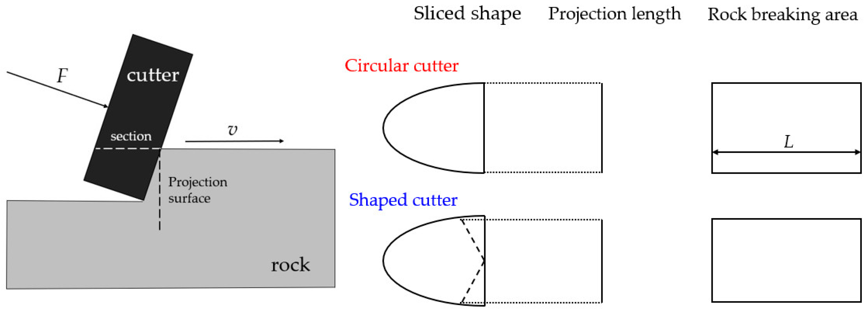
2. Evaluation Model of the Rock Breaking Efficiency of Special-Shaped Cutters Based on MSE

Mechanical specific energy (MSE) is an important factor in evaluating the drilling efficiency. The lower the mechanical specific energy (MSE), the higher the energy utilization rate of the cutter; thus, MSE is defined as the energy required to break a unit volume of rock:
M S E = W V
where W is the energy consumed by the cutter to break the rock, and V is the volume of the cutter required to break the rock.
The cutter–rock interaction model is established according to the cutter–rock interaction model of Detournay and Defourny [17], and the mechanical specific energy can be deduced by analyzing the force acting on the cutter. As shown in Figure 1, during the working process of the cutter, the weight on cutter (F) first exerts an oblique downward force on the cutter through the blade F. This force can be transformed into a cutting force in the same direction as the cutting process (Fh,) and a force perpendicular to the cutting direction (Fv). The cutter breaks the rock under the force of Fh; therefore, the work (W) of the cutting teeth on the rock and the rock breaking volume (V) are:
W = F h · L
V = A c · L
where L is the distance that the cutter moved, and AC is the rock breaking area, that is, the projection of the part of the cutter in contact with the rock on the vertical plane.
So, the expression of MSE can be written as:
M S E = F h A c
In the process of rock breaking with a special-shaped cutter, due to the change in the shape of the cutter surface, the rock breaking area will be different compared with the circular cutter, as shown in Figure 2. When the rock breaking distance (L) is the same, the larger the rock volume (V) broken by the special-shaped cutter with higher rock breaking area AC, the faster the rock breaking speed. The circular cutter breaking area (A0) is the reference value, creating a dimensionless quantity characterizing the shape change (α):
α = 2 A c A 0
The evaluation model of the rock breaking efficiency of the special-shaped cutter was obtained by modifying the MSE:
M S E * = α · M S E

3. Establishment of Cutting Gear Model and Calculation of Related Parameters

In order to accurately simulate the rock breaking process of the PDC cutters, modeling software was used to establish models of the commonly used special-shaped cutter structures (circular cutter, axe cutter, bevel cutter, wedge cutter, and triangular cutter), as shown in Figure 3, the diameter of the cutters was 16 mm. In the following, we report the main geometrical parameters we tested:
Axe cutter structure: ridge angle 120°;
Wedge cutter structure: tangent length 10 mm, slope 30°;
Triangular cutter structure: the angle between the ridges is 157°, the ridge length is 3 mm, slope 8°;
Bevel cutter structure: cone diameter 2 mm, cone angle 74°.
Due to the change in the cutter surface shape, the rock breaking area (Ac) of the special-shaped cutter at the same cutting depth (d) is different, thus the rock breaking area of various types of cutters at different cutting depths is also different. As shown in Figure 2, we took a cutter section and projected it onto the projection surface, the projection length was reduced due to the modification of the profiled cutter based on the circular cutter, because the rock breaking area of the profiled cutter section was smaller, resulting in a smaller rock breaking volume of the profiled cutter. Therefore, it was necessary to calculate the rock breaking area of the cutters according to the type and penetration depth (d) of the special-shaped cutter. Under the condition that the cutting angle was 15°, the rock breaking area of various PDC cutters is summarized in Table 1.

4. Numerical Simulation of Rock Breaking by Cutting

The Tarim Basin has experienced four periods of magmatic activity, including during the Sinian–Cambrian, Late Ordovician–Silurian, Permian, and Cretaceous; the Permian magmatic activity is the most intense and largest in scale. As a result, in the Permian strata, igneous rocks are widely distributed. In the study area of Shunbei Oilfield, the intensity of igneous rocks is the highest in the Permian, resulting in a significant decrease in the ROP in this section. In this study area, the igneous rock is located at a depth of 4000 m underground and has a thickness of about 400 m. In this article, igneous rock was used as the research object. The mechanical properties of the igneous rock formation were obtained by the logging data and are shown in Table 2.

4.1. Numerical Simulation of Cutter Rock Breaking

For the convenience of numerical calculation, the cutter was set as a rigid body, the damage of the cutter during drilling was ignored, and the rock element was deleted immediately after it failed. The cutter is shown on the left in Figure 4. The cutting angle of the cutter was 15°, and the side turning angle was 0°. The stratigraphic model was a semi-arc shape with an inner radius of 10 mm and an outer radius of 30 mm, and of 10 mm thickness (as shown in Figure 4).
The true stress–strain properties of rock materials are very complex, including nonlinear, elastic-plastic, viscoelastic, dilatancy, and anisotropy properties. For this reason, the linear Drucker–Prager plasticity model, which can better simulate rock materials, was selected for simulation calculation in this paper. We completed the construction of the rock model with the rock strength parameters listed in Table 2.
The rock and cutter used an eight-node reduced integration element (C3D8R) with hourglass control. The contact properties of the nodes and surfaces were used between the rock and the PDC cutter, and the friction factor of the contact surface was set to 0.25. In order to better achieve the simulation effect, the rock model was divided into 462,099 units. We constrained all degrees of freedom on the bottom face of the rock, leaving the remaining faces unconstrained. Rotate the cutter around the center point (RP-1). We used the ‘Explicit Dynamics Analysis Module’ to analyze the process of the cutter breaking rock.
Under the condition of deep well depth, it is not advisable to extract the rock from the ground and conduct cutting experiments to verify the model. Therefore, the accuracy of the model can be verified by calculating Fc of the cutter and comparing it with the numerical experimental results. To calculate the total cutting force of the PDC drill (Pc) [18], we used Equation (7).
P c = b d { cos ( α + φ ) cos ( β ) cos ( α + φ + γ + ψ ) ( cos ( γ ) 2 sin ( ψ ) c + ( cot ( ψ ) tan ( α ) ) sin ( γ ) P m ) + μ k sin ( α ) cos ( α ) C C S }
where b is the cutting width, d is the cutting depth, CCS is the compressive strength of the rock, μ is the coefficient of friction (0.25), φ is the friction angle between the cutter and the rock contact surface (10°), γ is the rock internal friction angle, Pm is hydrostatic pressure, c is the cohesion of the rock, ψ is the fracture angle of rock, and k is the rock correlation coefficient (which is 0.7 for hard rocks). The calculation method of the relevant parameters is presented in Equation (8).
{ P m = 0.00981 ρ D H ψ = 45 ° γ 2 α + φ 4 d = 50 R O P 3 R M P b = 2 r 2 ( r d ) 2
Subsequently, a well is selected for cutter cutting force analysis. In order to reduce the error of the bit vibration on the calculation results, the igneous rock in the stable section was selected as the research object, with a buried depth (DH) of 3800 m, mud density (ρ) of 1.1 g/cm3, back inclination angle (α) of 15°, side turning angle (β) of 5°, ROP of 5.2 m/h, rotary speed (RMP) of 42 r/min, cutter radius (r) of 8 mm, and the PDC bit drill with circular cutters. We then calculated the total cutting force of the PDC bit according to Equations (7) and (8) as 30,574.9 N.
As shown in Figure 5, the number of cutters (n) on the cutting surface of the drill bit is 24. According to Equation (9), the average cutting force (Fc*) of the cutter on the PDC bit was calculated as 1273.95 N. The numerical simulation model was used to conduct a simulation study under the same drilling parameters, and was compared with the calculation results (as shown in Figure 6). Taking the average of the numerical simulation results, Fc was 1225 N. Comparing numerical simulation results and calculation results, the error was only 4%, indicating that the numerical model is relatively accurate, and can be used for cutting simulation research.
F c * = P c n
Numerical simulation studies were carried out on the five cutter types, comprising the circular, wedge, triangular, axe, and bevel cutter, according to the experimental scheme in Table 3. Taking igneous rock as the research stratum, the rock breaking performance of the cutters at the cutting depths (d) of 2, 2.5, 3, and 4 mm under the conditions of a rotational speed of 80 r/min, a cutter diameter of 16 mm, and a back inclination angle of 15°, were calculated.

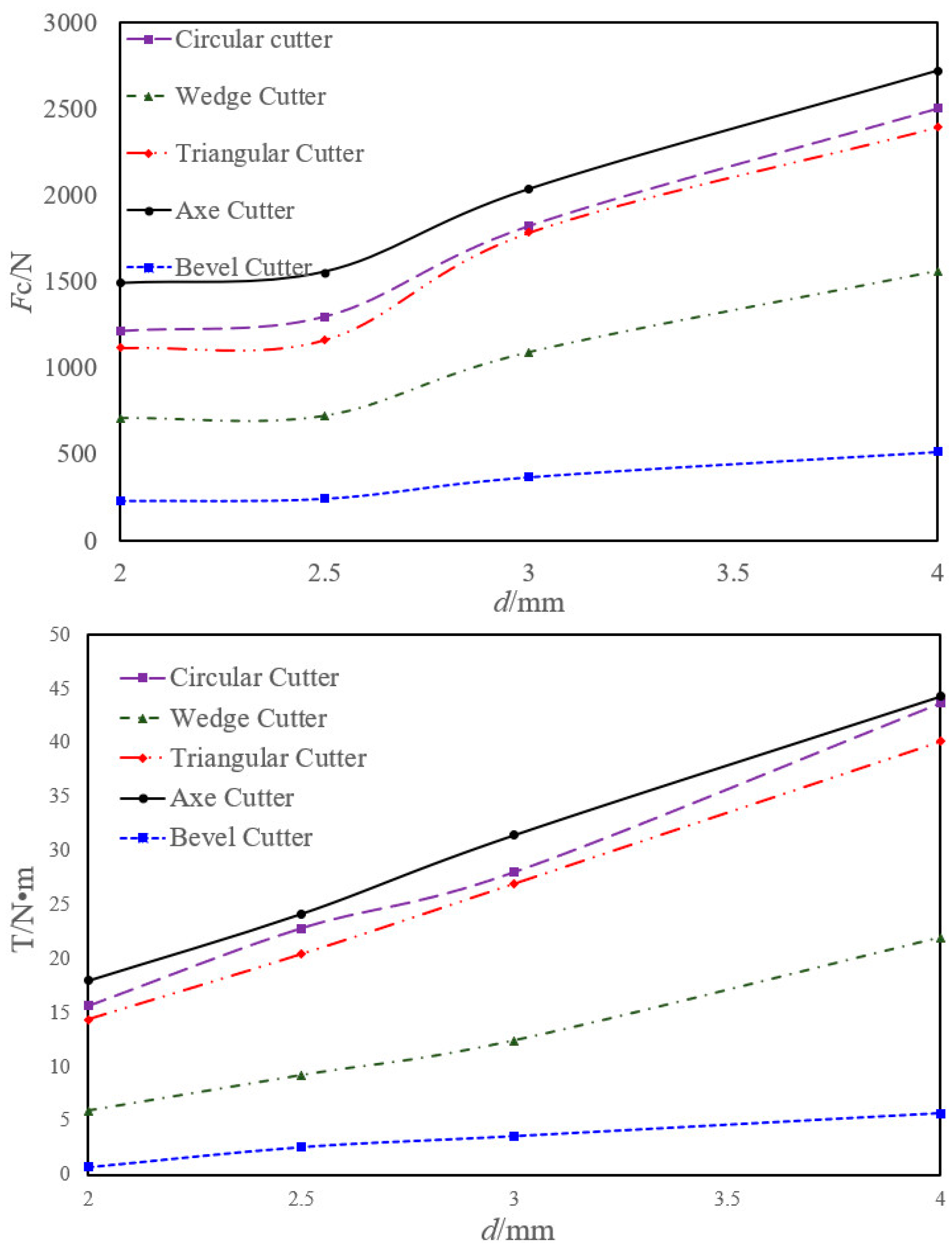
4.2. Numerical Simulation Results

Through numerical simulation analysis, the variation law of the cutting force (Fc) and torque (T) of the five kinds of cutting teeth with the penetration depth (d) was obtained (as shown in Figure 7). With the increase in the depth of penetration, the Fc and T required by the cutter both showed an upward trend. This is because with the increase in the cutting area (Ac), under the condition of a constant rotation rate, the rock breaking volume per unit time increased, and the cutting force required for breaking the rock increased, hence more energy was required. With the increase in d, the changes in Fc and T become more and more severe. This is because with the increase in weight on bit (WOB), the cutter gradually penetrated the formation; at the same time, with the increase in d, Ac increased faster and faster. More Fc and T were required to let the cutter to break the rock.
The experimental results show that the Fc and the T of the axe cutter, scallop cutter, and triangular cutter simulations were still relatively close, because the cutter surface shapes and Ac values of these three cutter types were similar. It is worth noting that compared with the circular cutter, the axe cutter had a smaller rock breaking area, but it required a larger Fc and T, because the obtuse angle on the surface of the axe cutter hindered rock breaking. It was designed to be arranged on the periphery of the drill bit to resist the shock impact in the drill bit working. The wedge cutter and the bevel cutter needed a small Fc and T to break the rock. This is because the tips of these two cutters were relatively sharp and could easily drill into the formation. At the same time, the Ac was smaller, and the formation resistance was lower. From the perspective of prolonging the service life of the cutters, the smaller the Fc that the cutters are subjected to in the process of breaking the formation, the better. Therefore, the tips of the cutters should be appropriately sharpened so that they can more effectively break the formation.
Through numerical simulation analysis, the variation law of the rock breaking specific energy (MSE) and rock breaking efficiency (MSE*) of five kinds of cutters with the penetration depth (d) was obtained (as shown in Figure 8). If d was too large or too small, the rock breaking specific work was larger, and there was a minimum rock breaking specific work value corresponding to the d in the middle. At the beginning, the MSE and MSE* were both large, which was caused by the shallow d and the small Ac. With the increase in d, values of Fc and Ac gradually increased. Since Fc increased slowly when d was shallow, the MSE and MSE* decreased first and then increased. This shows that the PDC cutter had an optimal WOB value, which corresponded to the optimal d of the cutter. Under this WOB, the cutter had a high rock breaking efficiency, low wear, and long service life. Therefore, an appropriate WOB should be selected during drilling to obtain a suitable penetration depth and a small rock breaking torque, to improve the service life of the cutter.
The analysis results of the rock breaking specific energy (MSE) of the five kinds of cutters correspond well with the Fc; the MSE of the wedge cutter and the bevel cutter were very similar. From the analysis results of the rock breaking efficiency (MSE*), the change in wedge cutter was the most obvious. This is mainly because the Ac of the wedge cutter was very small, and the volume of rock that could be broken was strongly limited when the PDC bit rotated. The MSE* of the bevel cutter was the best. On the one hand, the Fc required by the bevel cutter to break the rock was very small, and the MSE* was also very good, making it highly suitable for rock breaking. However, because the structure of the bevel cutter cannot resist the shock and impact of the drill bit, it should be used as a rear row on the cutter to assist in rock breaking. There were still no large differences between the axe cutter, circular cutter, and triangular cutter. In the front row of the cutter, the triangular cutter exhibited the best rock breaking efficiency, but it was easily worn due to the large forces; therefore, it should be used as the main cutter in medium–hard formations. In addition to the wedge cutter exhibiting high rock breaking efficiency, enabling it to easily drill into the rock, the cutter was not easily worn and had a long life. Consequently, the wedge cutter is recommended as the main rock-breaking cutter for hard formations.

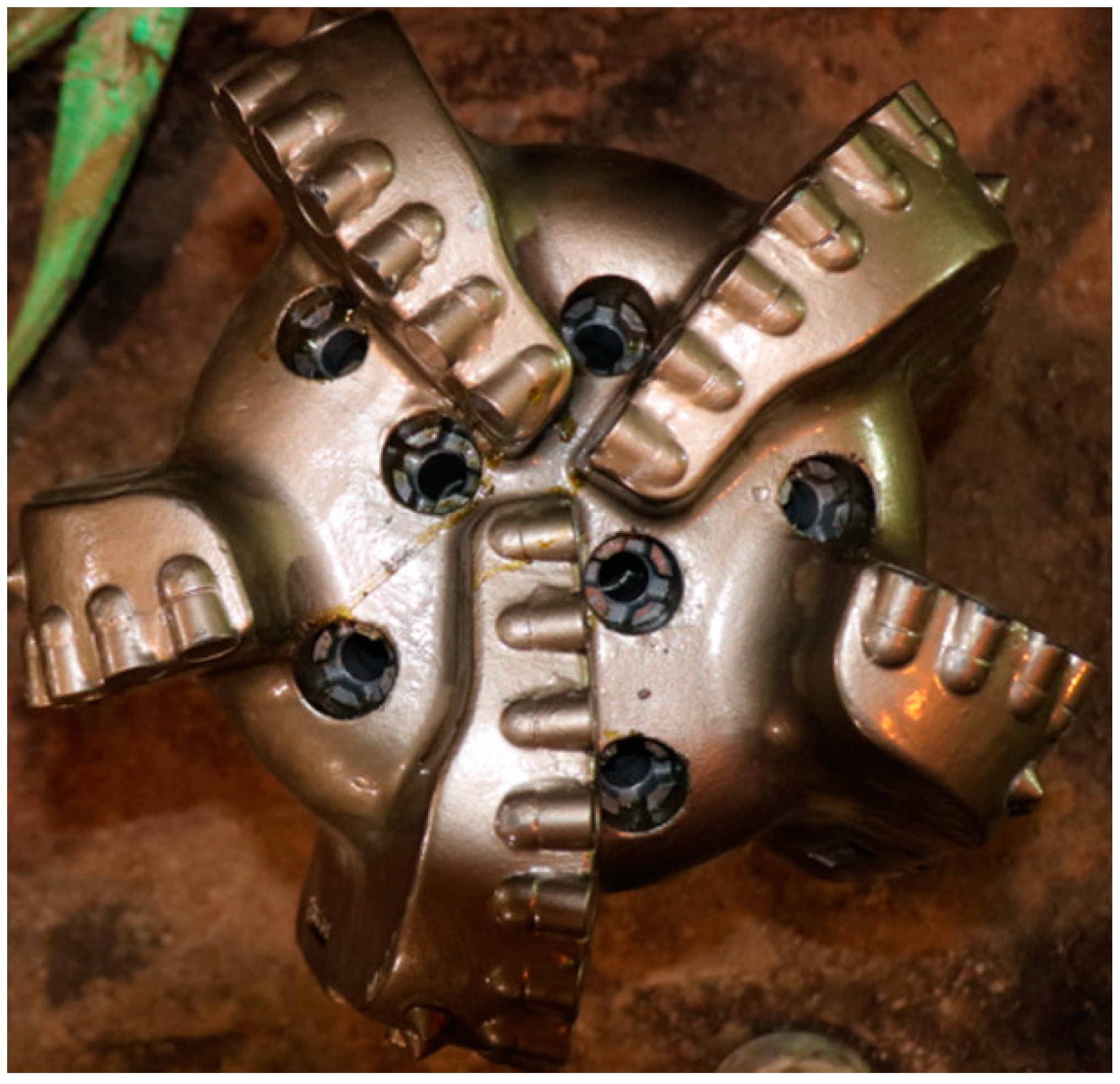
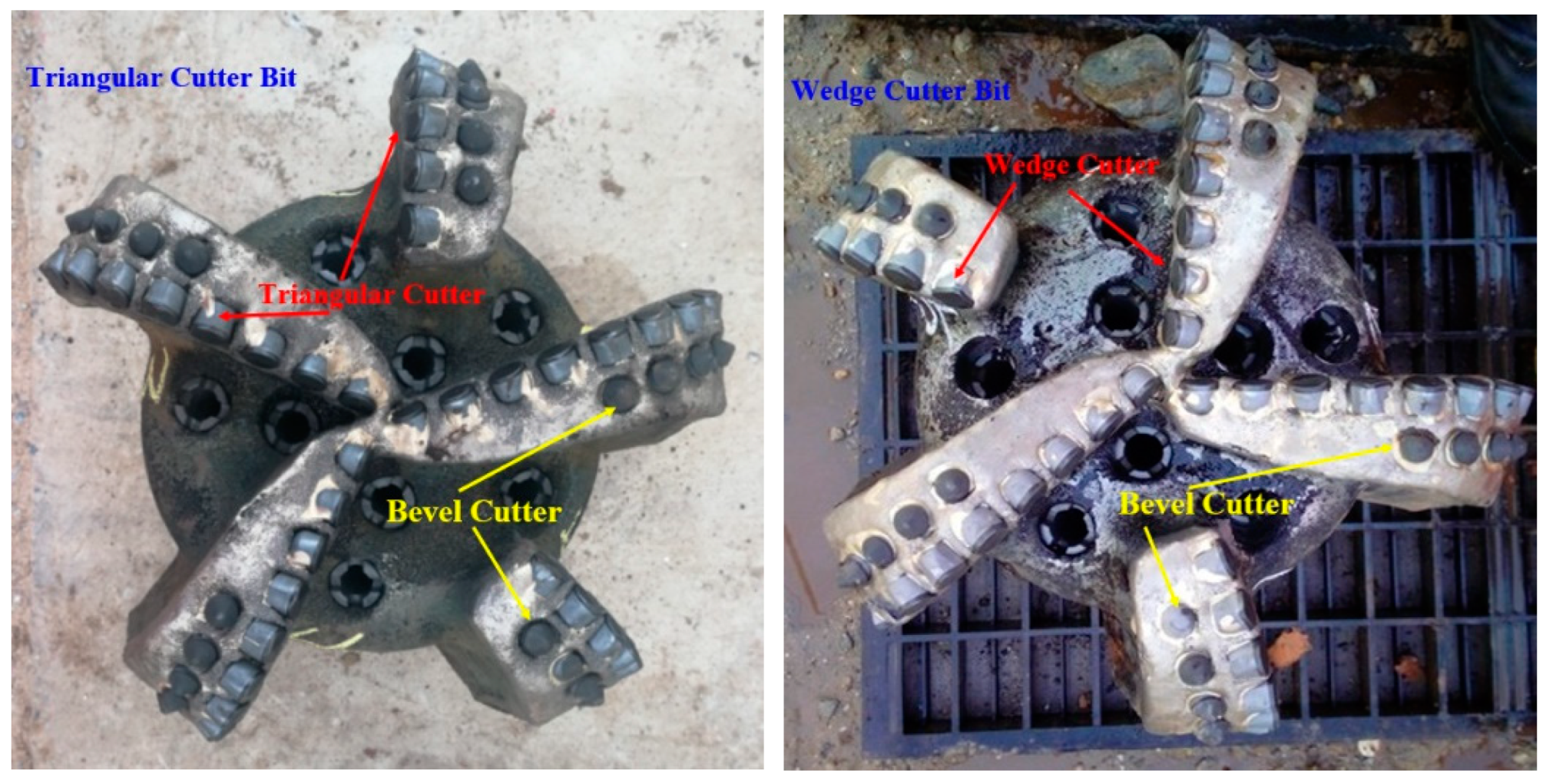
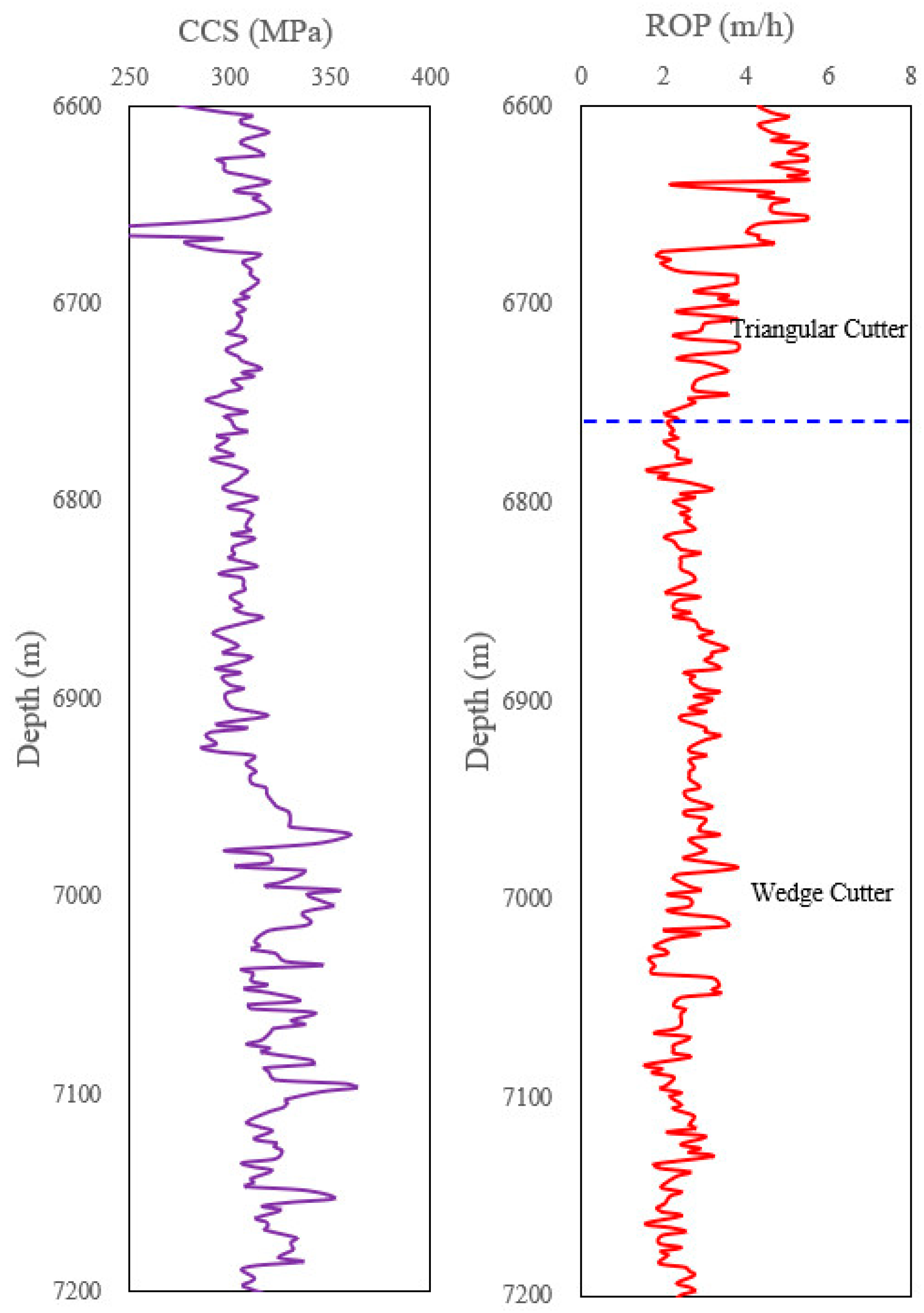
5. Experimental Study on Rock Breaking with Full-Size Drill Bits

In order to prove the accuracy of the research results, a field experiment was designed and carried out using the bevel cutter as the rear cutter, with either the triangular cutter or the wedge cutter as the front cutter. The experiment was conducted in the ultradeep layer of high temperature and high pressure, at a depth of 6600 m to 7200 m. The formation was interbedded with limestone and mudstone, but under the action of the high confining pressure, the compressive strength (CCS) of the rock formation was very high. Figure 9 shows the PDC bit used in the experiment.
The ROPs of the two drills were compared (as shown in Figure 10). The compressive strength (CCS) of the rock was relatively uniform during the experiment. At 6600–6780 m, the triangular cutter bit was used for rock breaking; below 6780 m, the wedge cutter bit was used for rock breaking. As can be seen from the ROP variation curve, while drilling, the rock breaking efficiency of the triangular cutter was obviously better than that of the wedge cutter. However, from the well exit of the drill bit, the wear of the triangular cutter was more serious, indicating that the Fc required for rock breaking was relatively large. It was easy to wear and tear, which verified the accuracy of the numerical simulation study.

6. Conclusions

In this paper, five kinds of commonly used cutters were selected to carry out a cutter-based rock breaking numerical simulation experiment, and the influence of the change in the special-shaped cutter surface on the rock breaking efficiency was considered. The MSE* method was designed and used to evaluate the rock breaking efficiency of the cutters. Compared with the traditional MSE method, this method can reflect the differences between cutters surface. Using the MSE* method and the experimental results of the numerical simulation, the cutter profile suitable for drilling into hard formation was optimized.
(1) With the increase in penetration depth, both the cutting force (Fc) and the torque (T) required by the cutter showed an upward trend. As expected, the changes in the Fc and T became more and more severe. Among the five kinds of cutters tested, the Fc and T required by the wedge cutter and the bevel cutter more easily broke the formation, and the service life of the cutters was longer.
(2) If the penetration depth was too long or too short, the breaking specific work of the rock was unsuitable, and the rock breaking efficiency reached its highest at the appropriate penetration depth. The PDC cutter had an optimal WOB value, which corresponded to the optimal penetration depth of the cutter. Under this WOB, the cutter had high rock breaking efficiency, low wear, and long service life. Therefore, an appropriate WOB should be selected during drilling to obtain a suitable penetration depth and a small rock breaking torque, to improve the service life of the cutter.
(3) Triangular cutters are suitable for drilling into medium–hard formations because of their high rock breaking efficiency and low wear life. The wedge cutter had a low rock breaking efficiency, easily intruding into the rock, with a long anti-wear life, which is suitable for drilling into hard formations. The bevel cutter was excellent in all aspects; however, because they cannot resist the shock and impact of the drill bit in work, they are more suitable as the rear cutter to assist in rock breaking.
(4) Through the rock breaking experiment of full-size drill bits at a depth of 6600–7200 m, the results show that the drilling speed of the triangular cutter was obviously better than that of the wedge cutter. However, the triangular cutter wear was more serious, which proves the reliability of the numerical simulation results.

Author Contributions

Conceptualization, Z.D. and H.Z.; methodology, Z.D.; validation, Z.D.; formal analysis, Z.D. and J.L.; investigation, Z.D., H.Z., K.Z., Y.O., Z.L. and J.S.; data curation, K.Z., Y.O., Z.L. and J.S.; supervision, H.Z.; project administration H.Z. and J.L.; funding acquisition, H.Z. and J.L.; writing—original draft, Z.D.; writing—review and editing, H.Z. All authors have read and agreed to the published version of the manuscript.

Funding

This research was supported by the Sinopec Joint Fund; U19B6003, Hui Zhang; Ladder Plasma Fund; 52174010, Hui Zhang; CNPC strategic cooperation project Mahu; ZLZX2020-01, Hui Zhang and Jun Li; Key Projects of University Scientific Research Program in Xinjiang Uygur Autonomous Region; XJEDU20211028, Jun Li.

Institutional Review Board Statement

Not applicable.

Informed Consent Statement

Not applicable.

Data Availability Statement

Not applicable.

Conflicts of Interest

The authors declare no conflict of interest.

References

  1. Teale, R. The concept of specific energy in rock drilling. Int. J. Rock Mech. Min. Sci. Geomech. Abstr. 1965, 2, 57–73. [Google Scholar] [CrossRef]
  2. Pessier, R.C.; Fear, M.J. Quantifying Common Drilling Problems With Mechanical Specific Energy and a Bit-Specific Coefficient of Sliding Friction. In Proceedings of the SPE Annual Technical Conference and Exhibition, Washington, DC, USA, 4–7 October 1992; OnePetro: Lawrence, KS, USA, 1992. [Google Scholar]
  3. Waughman, R.J.; Kenner, J.V.; Moore, R.A. Real-Time Specific Energy Monitoring Enhances the Understanding of When To Pull Worn PDC Bits. SPE Drill. Complet. 2003, 18, 59–67. [Google Scholar] [CrossRef]
  4. Hammoutene, C.; Bits, S. FEA Modelled MSE/UCS Values Optimise PDC Design for Entire Hole Section. In Proceedings of the North Africa Technical Conference and Exhibition, Cairo, Egypt, 20–22 February 2012; OnePetro: Lawrence, KS, USA, 2012. [Google Scholar]
  5. Rashidi, B.; Hareland, G.; Nygaard, R. Real-Time Drill Bit Wear Prediction by Combining Rock Energy and Drilling Strength Concepts. In Proceedings of the Abu Dhabi International Petroleum Exhibition and Conference, Abu Dhabi, United Arab Emirates, 3–6 November 2008; OnePetro: Lawrence, KS, USA, 2008. [Google Scholar]
  6. Mohan, K.; Adil, F.; Samuel, R. Tracking Drilling Efficiency Using Hydro-Mechanical Specific Energy. In Proceedings of the SPE/IADC Drilling Conference and Exhibition, Amsterdam, The Netherlands, 17–19 March 2009; OnePetro: Lawrence, KS, USA, 2009. [Google Scholar]
  7. Rashidi, B.; Hareland, G.; Fazaelizadeh, M.; Svigir, M. Comparative Study Using Rock Energy And Drilling Strength Models. In Proceedings of the 44th U.S. Rock Mechanics Symposium and 5th U.S.-Canada Rock Mechanics Symposium, Salt Lake City, UT, USA, 27–30 June 2010; OnePetro: Lawrence, KS, USA, 2010. [Google Scholar]
  8. Koederitz, W.L.; Johnson, W.E. Real-Time Optimization of Drilling Parameters by Autonomous Empirical Methods. In Proceedings of the SPE/IADC Drilling Conference and Exhibition, Amsterdam, The Netherlands, 1 March 2011; OnePetro: Lawrence, KS, USA, 2011. [Google Scholar]
  9. David, H.; Saeed, S.; Fatemeh, K.S. An Integrated Approach for Drilling Optimization Using Advanced Drilling Optimizer. J. Pet. Eng. 2015, 2015, 281276. [Google Scholar]
  10. Dupriest, F.E.; Koederitz, W.L. Maximizing Drill Rates with Real-Time Surveillance of Mechanical Specific Energy. In Proceedings of the SPE/IADC Drilling Conference, Amsterdam, The Netherlands, 23–25 February 2005; OnePetro: Lawrence, KS, USA, 2005. [Google Scholar]
  11. Amadi, K.; Iyalla, I. Application of Mechanical Specific Energy Techniques in Reducing Drilling Cost in Deepwater Development. In Proceedings of the SPE Deepwater Drilling and Completions Conference, Galveston, TX, USA, 20 June 2012; OnePetro: Lawrence, KS, USA, 2012. [Google Scholar]
  12. Armenta, M. Identifying Inefficient Drilling Conditions Using Drilling-Specific Energy. In Proceedings of the SPE Annual Technical Conference and Exhibition, Denver, CO, USA, 21–24 September 2008; OnePetro: Lawrence, KS, USA, 2008. [Google Scholar]
  13. Khalilidermani, M.; Knez, D. A Survey of Application of Mechanical Specific Energy in Petroleum and Space Drilling. Energies 2022, 15, 3162. [Google Scholar] [CrossRef]
  14. Pryhorovska, T.O.; Chaplinskiy, S.S.; Kudriavtsev, I.O. Finite element modelling of rock mass cutting by cutters for PDC drill bits. Pet. Explor. Dev. 2015, 42, 888–892. [Google Scholar] [CrossRef]
  15. Ju, P.; Wang, Z.; Zhai, Y.; Su, D.; Zhang, Y.; Cao, Z. Numerical simulation study on the optimization design of the crown shape of PDC drill bit. J. Pet. Explor. Prod. Technol. 2014, 4, 343–350. [Google Scholar] [CrossRef] [PubMed]
  16. Martinez, I.R.; Fontoura, S.; Inoue, N.; Carrapatoso, C.; Lourenco, A.; Curry, D. Simulation of Single Cutter Experiments in Evaporites Through Finite Element Method. In Proceedings of the SPE/IADC Drilling Conference, Amsterdam, The Netherlands, 5–7 March 2013; OnePetro: Lawrence, KS, USA, 2013. [Google Scholar]
  17. Detournay, E.; Defourny, P. A phenomenological model for the drilling action of drag bits. Int. J. Rock Mech. Min. Sci. Geomech. Abstr. 1992, 29, 13–23. [Google Scholar] [CrossRef]
  18. Zhou, Y. Study on the Mechanism and Application of Speed Increase in Torsional Impact Drilling; China University of Petroleum (East China): Qingdao, China, 2018. (In Chinese) [Google Scholar]
Figure 1. The cutter–rock interaction model.
Energies 15 06686 g001
Figure 2. Sectional shape and crushing area of circular cutter and special-shaped cutter.
Energies 15 06686 g002
Figure 3. Shaped cutter and its model establishment.
Energies 15 06686 g003
Figure 4. Numerical simulation model of a cutter breaking rock.
Energies 15 06686 g004
Figure 5. Front view of the PDC bit used for 3800 m depth.
Energies 15 06686 g005
Figure 6. Comparison of numerical simulation (Fc) and cutting force calculation (Fc*).
Energies 15 06686 g006
Figure 7. Numerical simulation results of Fc and T. The top subfigure is the curve of Fc with d; the bottom subfigure is the curve of T with d.
Energies 15 06686 g007
Figure 8. Numerical simulation results of the MSE and MSE*. The top subfigure is the curve of the MSE with d; the bottom subfigure is the curve of MSE* with d.
Energies 15 06686 g008
Figure 9. The photo of the field test PDC bit after use. On the left is the triangular cutter bit, on the right is the wedge cutter bit.
Energies 15 06686 g009
Figure 10. Variation curves of the CCS and ROP with well depth. On the left is the CCS curve with depth, on the right is the ROP curve with depth.
Energies 15 06686 g010
Table 1. Statistical table of the change in rock breaking area of the PDC cutters with the penetration depth.
d
(mm)
Circular Cutter
(mm2)
Wedge Cutter
(mm2)
Triangular Cutter
(mm2)
Axe Cutter
(mm2)
Bevel Cutter
(mm2)
214.746.8513.9713.496.70
2.520.3810.1119.4318.8612.81
326.4913.9325.3224.7321.58
439.8424.0438.4737.6829.59
Table 2. Mechanical properties of igneous rocks.
Elastic Modulus/10 GPaCompressive Strength/MPaPoisson’s RatioInternal Friction Angle/°
4.07104.860.3138.71
Table 3. Numerical simulation experiment scheme of cutter breaking rock.
Rockd (mm)Rotating Speed (r/min)Diameter (mm)Caster Angle (°)
Igneous rock2801615
2.5
3
4
Publisher’s Note: MDPI stays neutral with regard to jurisdictional claims in published maps and institutional affiliations.

