Article

The Effect of the Load Power Factor of the Inductive CT’s Secondary Winding on Its Distorted Current’s Harmonics Transformation Accuracy

Institute of Mechatronics and Information Systems, Lodz University of Technology, 90-537 Lodz, Poland
*
Author to whom correspondence should be addressed.
Energies 2022, 15(17), 6258; https://doi.org/10.3390/en15176258
Submission received: 2 August 2022 / Revised: 23 August 2022 / Accepted: 25 August 2022 / Published: 27 August 2022
(This article belongs to the Special Issue Development of Voltage and Current Transformers in Power System)

Abstract

:
In this paper, we present an investigation into the influence of the load power factor of secondary winding on the metrological performance of inductive CTs with frequencies from 50 Hz to 5 kHz of the harmonic of a transformed distorted current. The results clearly indicated that the inductive load caused a deterioration in the transformation accuracy of the inductive CT. To ensure the most advantageous conditions of their operation, a resistive load should be used. The inductive CTs for the frequencies of the transformed harmonic of a distorted primary current from 50 Hz to 5 kHz may ensure the accuracy class designated for the transformation of the sinusoidal current of a frequency of 50 Hz with the same limiting values of errors. Moreover, an analysis of the generated low-order harmonics by a 300 A/5 A CT determined for the power factor of 0.8 inductive and 1.0 of the secondary winding was investigated. These results for the transformed distorted currents of 3rd, 5th and 7th higher harmonics were evaluated for a rated load and 25% of this value.

1. Introduction

Inductive current transformers (CTs) are widely used in electrical grids to convert a high current into an acceptable level by measuring and by protection apparatus [1,2,3,4,5]. The distortion of currents causes CTs to be forced to transform non-sinusoidal currents with a significant content of higher harmonics. Therefore, it is important to obtain the most advantageous conditions of their operation in order to ensure the highest accuracy. There are no defined IEC standard requirements for the transformation of distorted currents by inductive CTs. The limits of the ratio error and phase displacement for measuring inductive CTs are defined in the IEC standards only for sinusoidal currents [6]. The burden used as load of the secondary winding during the accuracy test for all classes should have a power factor of 0.8 inductive if the burden is higher than or equal to 5 VA. In other cases, a power factor of 1.0 should be used, with a minimum value of 1 VA. In the case of the protective CTs of classes P and PR, the same burden requirements are defined. IEC standard 61869-6 defines the metrological requirements for the transformation of a distorted current only by low-power instrument transformers (devices designed to be loaded with negligible power) [7]. To characterise the wideband metrological properties of inductive CTs, an IEC technical report about the use of instrument transformers for power quality measurements has been published. This document contains information about the behaviour of inductive and electronic instrument transformers operating with a non-sinusoidal current and voltage. Moreover, a measuring setup with a two-channel synchronous analogue to digital converter to determine their wideband metrological properties has been proposed [8,9,10,11,12]. The continuation of these studies is the aim of many published scientific papers [13,14,15,16,17,18,19]. In [20], an alternative differential measuring setup characterised by a lower measurement uncertainty was developed. The results indicated that the wideband metrological performance of inductive CTs significantly depends on the phase angle of the transformed higher harmonics of the distorted primary current related to its main component. In the case of devices with a magnetic core, this is a result of the self-generation of low-order higher harmonics in the secondary current caused by a non-linear magnetisation curve. Moreover, the distortion of the primary current may increase the peak value of the magnetic flux density and change the values and phases of the self-generated low-order higher harmonics [21]. An accuracy test of the inductive CTs may be performed with the utilisation of the rated ampere turns method. This solution is only applicable to window-type inductive CTs. In other cases, its primary winding must be fed by a rated current, which may be generated by a step-up current transformer with a wideband power amplifier [22,23,24]. The results and analysis in [25] are helpful to understand the course of the wideband metrological characteristics of a corrected inductive CT [26]. The proposed vectorial diagrams define the components conditioning the values of the current error and phase displacement of the harmonic of the specified distorted current. Several works have been dedicated to developing a compensation technique for the self-distortion of inductive CTs [27,28,29,30]. However, due to the effect of the low-order harmonics presented in [21], such solutions are not effective.
In this paper, the power factor influence of the load connected to a secondary winding on the metrological performance of inductive CTs with frequencies from 50 Hz to 5 kHz of the harmonic of a transformed distorted current was analysed. We compared the values of the current error and phase displacement determined at the harmonics of the distorted primary current for the tested CT whilst operating with a secondary winding load power factor equal to 1.0 and 0.8 inductive. During the test, the apparent load power remained constant. The increase in the order of the transformed harmonic caused an increase in the secondary voltage of the CT and thereby increased the value of the magnetic flux density of the core. Therefore, a deterioration in the inductive CT transformation accuracy increased with the order of the distorted current harmonic. The results clearly indicated that the inductive load caused the deterioration of the inductive CT transformation accuracy. To ensure the most advantageous conditions of their operation, a resistive load should be used. Inductive CTs operating with a distorted primary current with a harmonic up to a 100th order may then ensure the accuracy class designated for the transformation of a sinusoidal current with a frequency of 50 Hz with the same limiting values of errors. A resistive load of the secondary winding of the CT may be achieved in real operating conditions when a shunt resistor is used as the input converter for an analogue to digital converter of a power measuring device or protection apparatus. Moreover, in this paper, we investigated an analysis of the generated harmonics by a 300 A/5 A CT determined for a power factor of 0.8 inductive and 1.0 of the secondary winding. These results for the transformed distorted currents of the 3rd, 5th and 7th higher harmonics were evaluated for a rated load and 25% of this value. We focused on these harmonics because with higher order harmonics, the self-generation is negligible. The novelty of the presented results and analysis were:
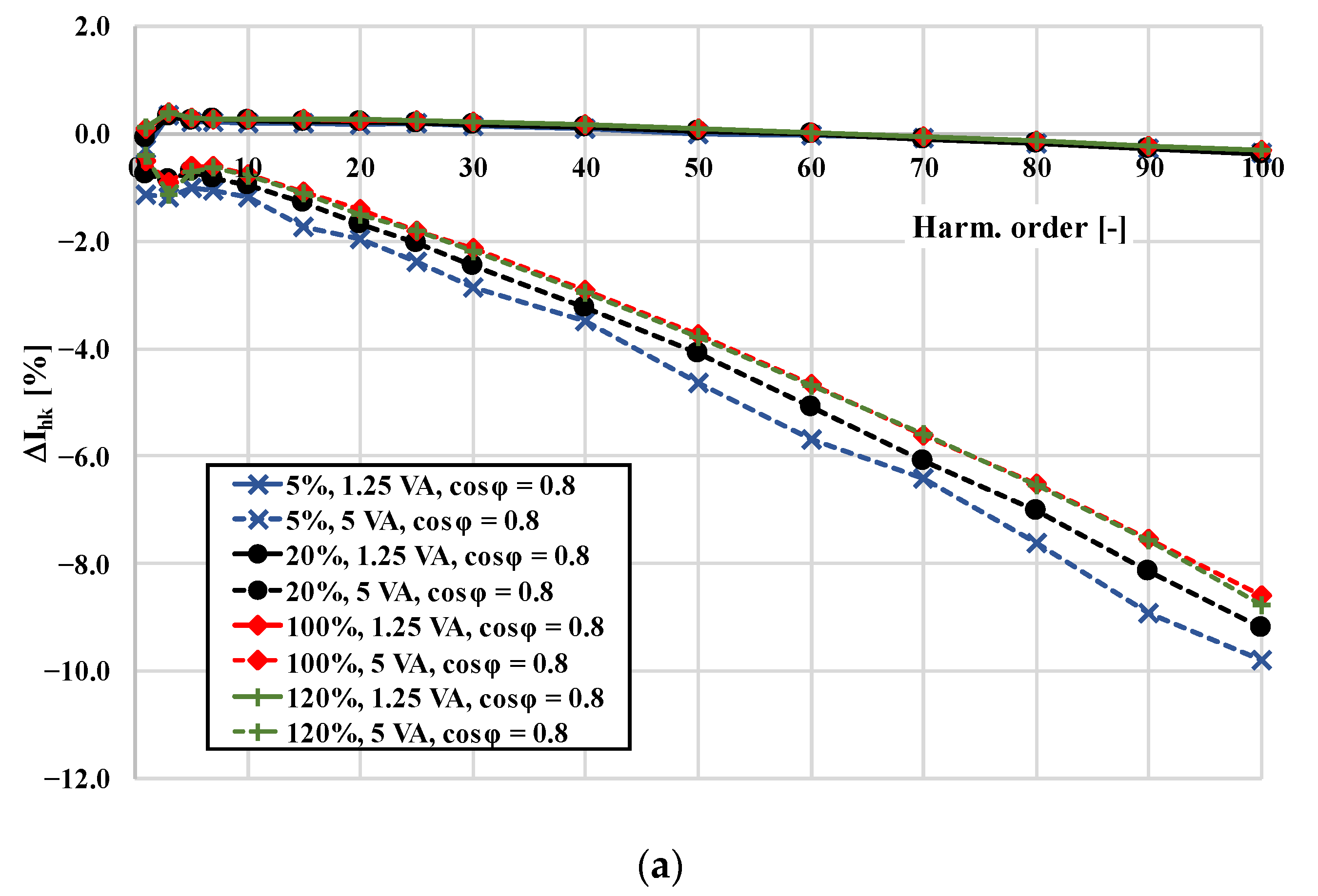
  • A comparison of the values of the current error and phase displacement determined for the same inductive CT when the load of its secondary winding was purely resistive and when its power factor was 0.8 inductive;
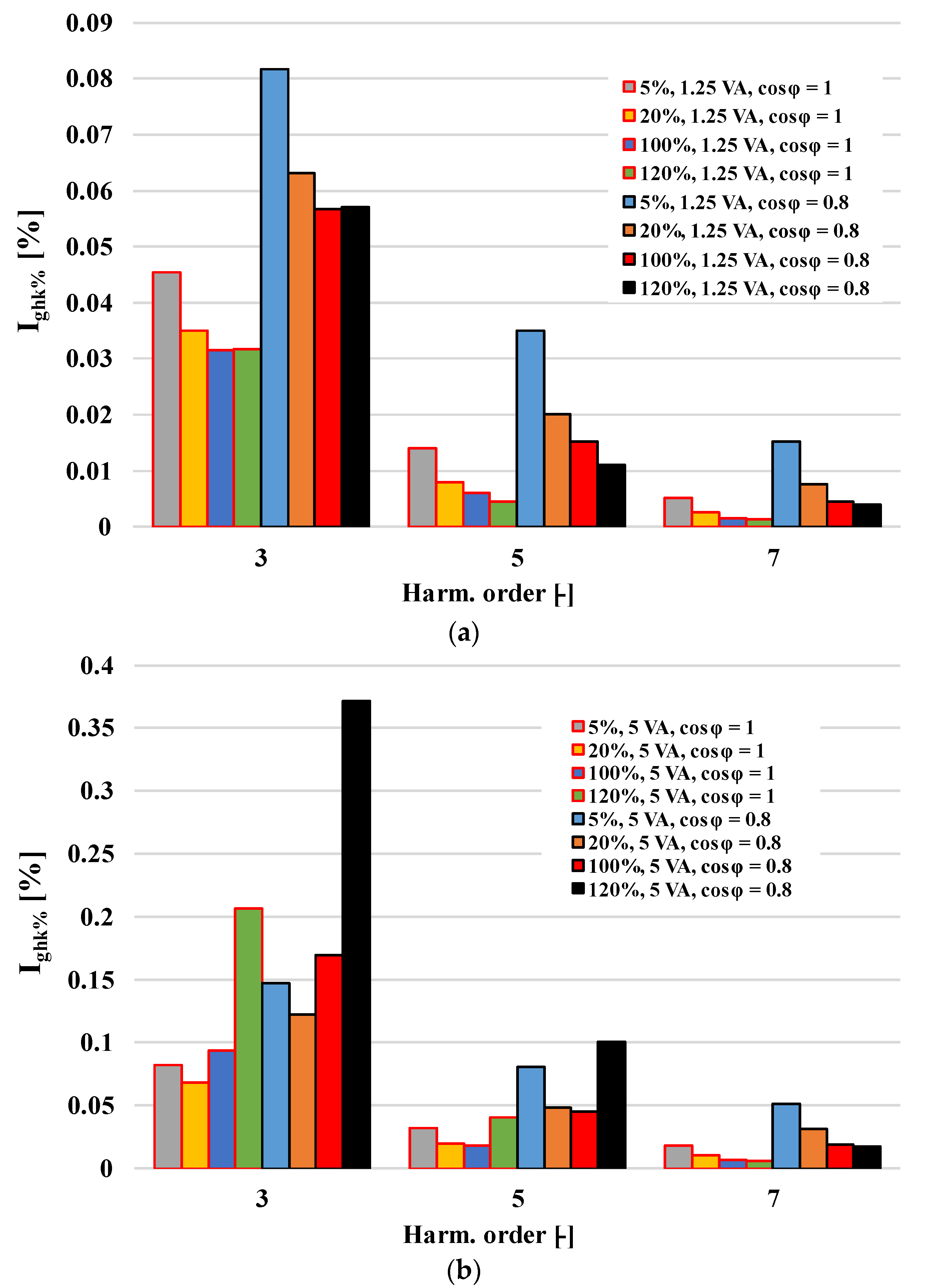
  • An evaluation of the generation level of the harmonics in conditions when the load of its secondary winding was purely resistive and when its power factor was 0.8 inductive;
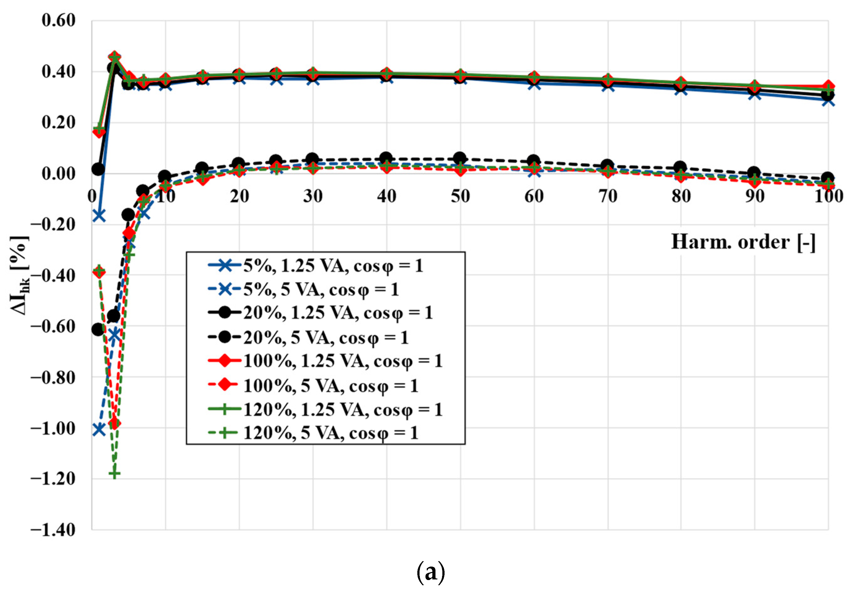
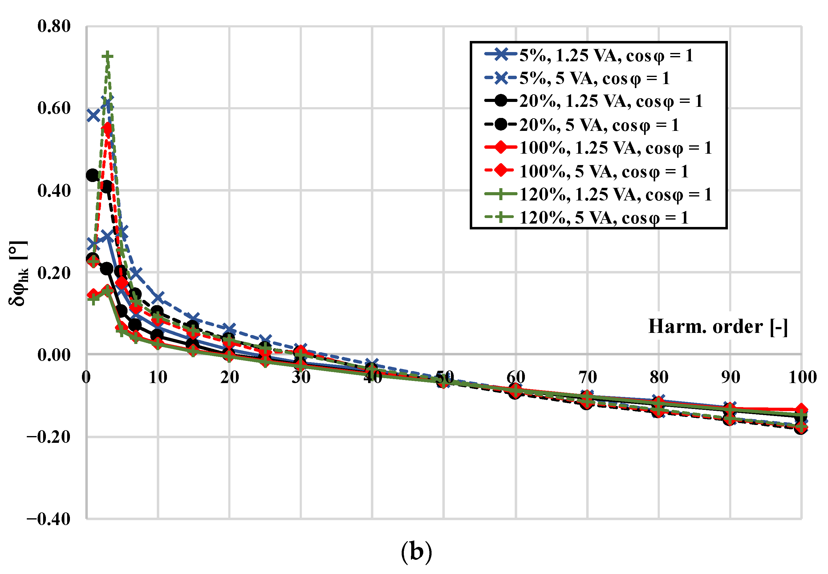
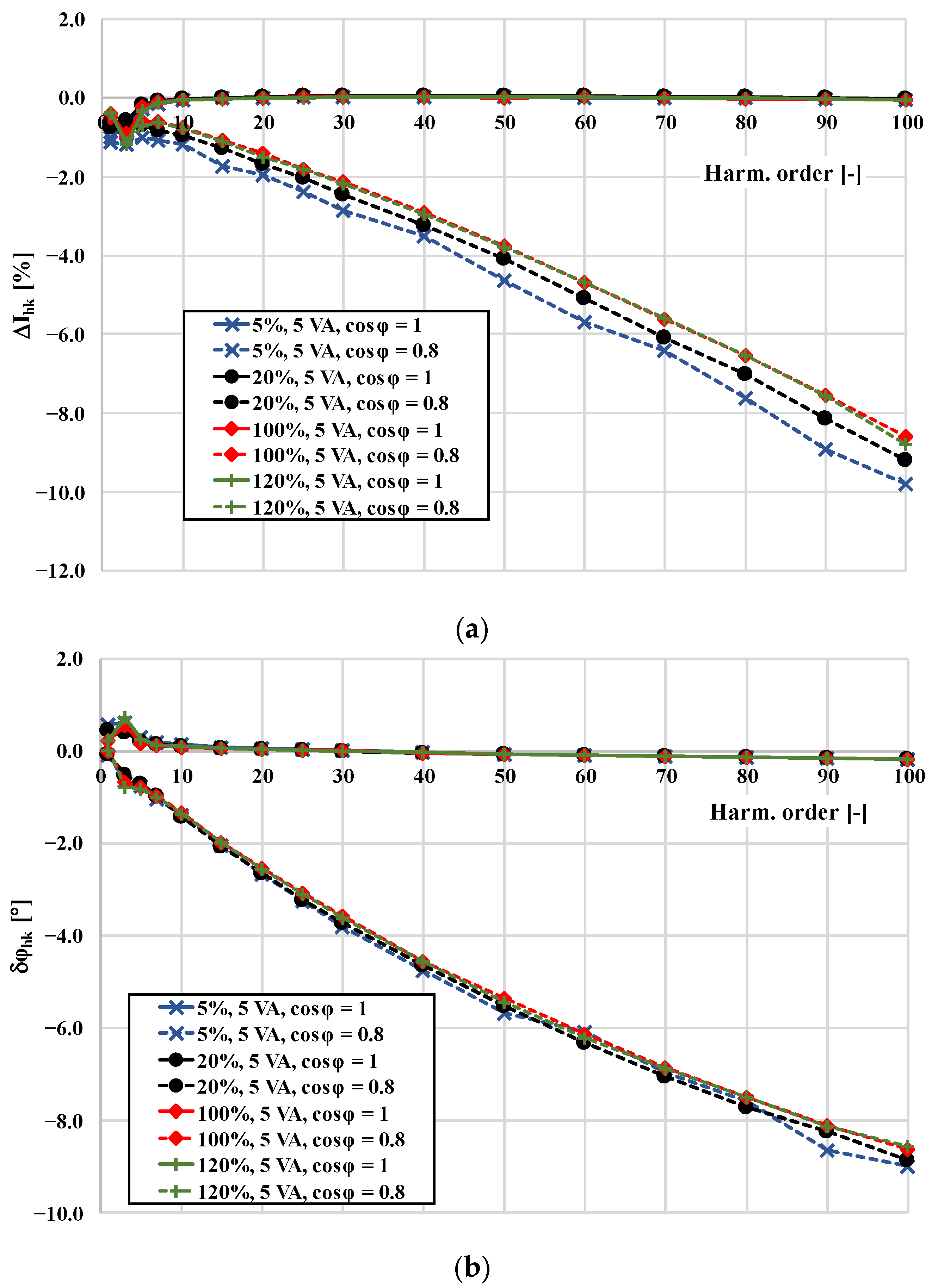
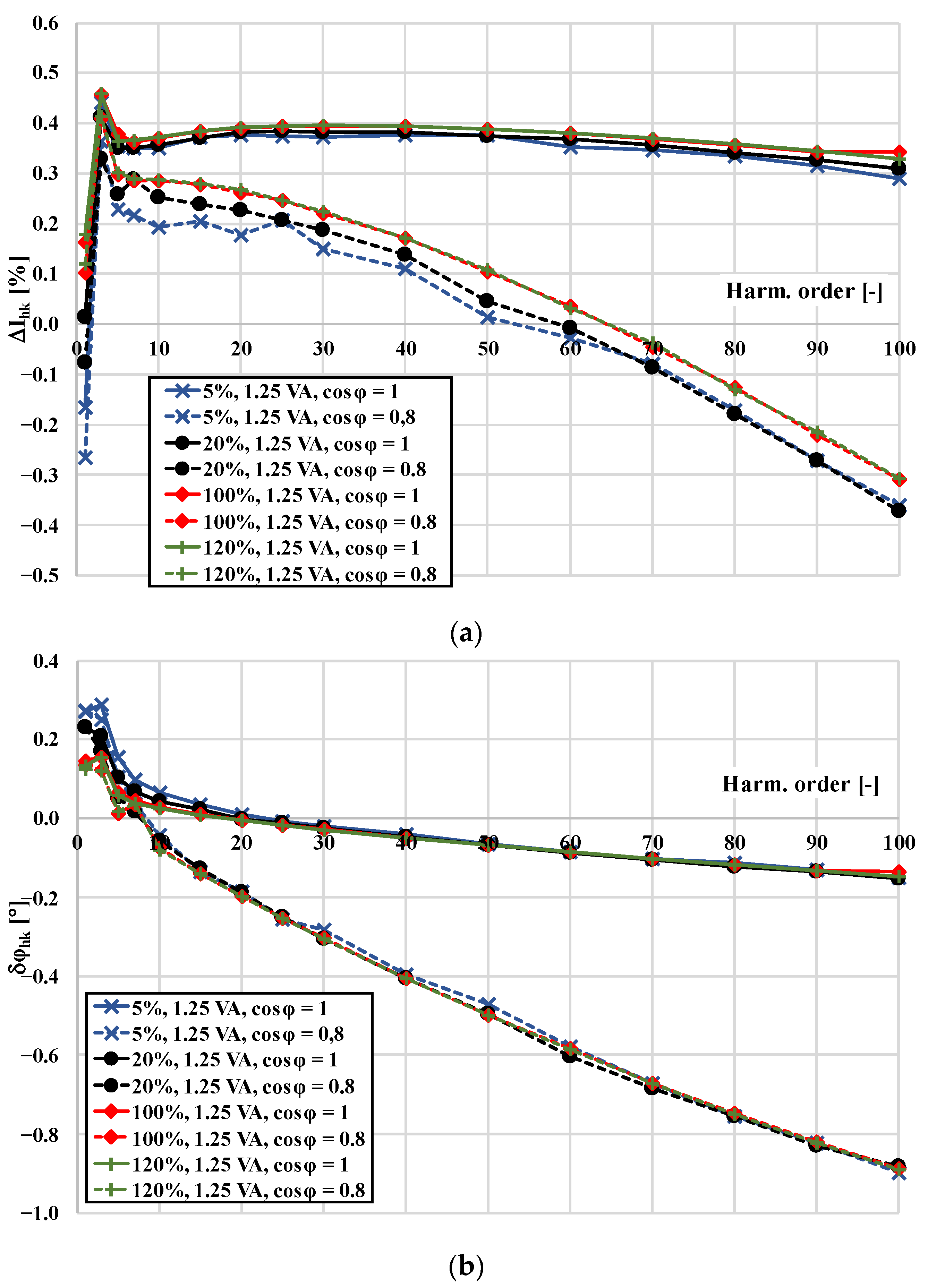
  • An analysis of the change with the frequency of the current error and phase displacement at harmonics for different power factors of the secondary winding load of the CT;
  • The designation of the conditions that ensured the highest accuracy of the inductive CTs during a distorted current transformation;
  • The justification of the applicability of a resistive load for an inductive CT when used for the evaluation of the power quality or a distorted power meeting.

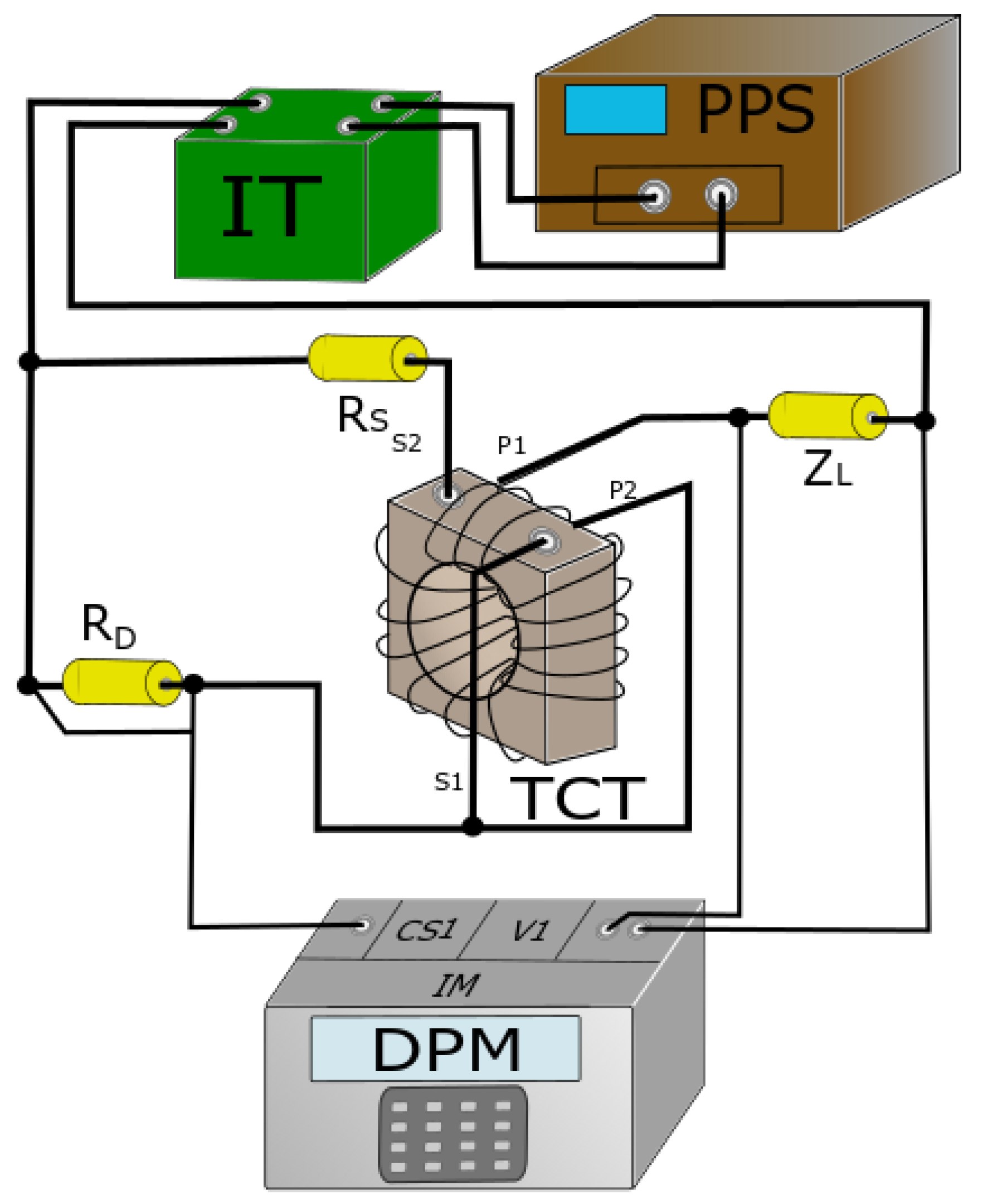
2. The Measuring Circuit and the Objects of the Research

The effect of the load power factor of the secondary winding on the harmonics of its distorted current transformation accuracy was analysed for a 300 A/5 A inductive CT. This unit was designed for a rated load of the secondary winding equal to 5 VA (power factor 0.8). The tests were performed utilising the rated ampere turns method. Therefore, a primary winding with 60 turns was additionally made.
In Figure 1, the measuring setup used for the evaluation of the values of the current error and phase displacement of the CTs is presented.
In Figure 1, the following abbreviations are used:
IT: isolating transformer;
PPS: programmable power source;
RS: current shunt used to measure the RMS value of a given primary current harmonic;
RD: current shunt used to measure the RMS value of a given differential current harmonic;
ZL: impedance of the load of the secondary winding: resistive (power factor 1) or resistive-inductive (power factor 0.8);
DPM: digital power meter;
TCT: tested inductive current transformer.
In the presented measuring system, the accuracy of the inductive CT was evaluated from three measured quantities. In the same channel of DPM for a specified hk harmonic, the RMS values of the current in the additional primary winding and the differential current (between the additional primary and secondary windings) as well as the phase angle between these currents were simultaneously measured. Therefore, this approach decreased the measurement uncertainty [21].
The value of the current error of a given harmonic could be calculated using the following equation [20,24]:
Δ I h k =   U S h k R S 2 + U D h k R D 2 2 ·   U S h k R S · U D h k R D · cos ϕ A h k   U S h k R S   U S h k R S · 100 %
where UDhk is the RMS value of a given voltage harmonic on current shunt RD, ϕAhk is the phase angle of a given harmonic between the voltages on current shunts RD and RS and UShk is the RMS value of a given voltage harmonic on current shunt RS.
The value of the phase displacement of a given harmonic was specified by the formula [20,24]:
δ φ h k = a r c s i n 1 100 % · U D h k R D   U S h k R S · 100 %   U S h k R S 2 + U D h k R D 2 2 ·   U S h k R S · U D h k R D · cos ϕ A h k   U S h k R S   U S h k R S · 100 %   1 2 .

3. Metrological Performance of the CTs in a Wide Frequency Range

To determine the values of the transformation errors, the equivalent ampere turns conditions of the CT under test were used with the utilisation of the differential current measurements in the measuring circuit, as presented in Figure 1. The results concerned the conditions when the distorted current contained one higher harmonic of frequency from 100 Hz to 5 kHz.
In Figure 2, the results of the measurements are presented for the rated resistive load (5 VA, cosφ = 1) of the secondary winding (solid lines) and for 25% of the rated load (1.25 VA, cosφ = 1; dashed lines) as well as for four percentage values equal to 5%, 20%, 100% and 120% of the rated primary current (I1N).
The high values of the obtained current errors and phase displacements up to the 10th order of harmonics were caused by the generation of harmonics in the secondary current by the tested CT. This resulted from the non-linearity of the magnetisation characteristics of the magnetic core. This phenomenon has been discussed in detail in many articles [20,21,24,31]. In these conditions, the highest current error values occurred for 120% I1N and 25% SN. Moreover, the applied correction of turns of the secondary winding caused a shift of the current error value in a positive direction [26]. As the load on the secondary winding increased, the current error values moved toward a negative value. The most significant phase displacement occurred for 5% I1N and SN.
In Figure 3, the results of the measurements are presented for the rated load (5 VA, cosφ = 0.8) of the secondary winding (solid lines) and for 25% of the rated load (1.25 VA, cosφ = 0.8; dashed lines) for four percentage values equal to 5%, 20%, 100% and 120% of I1N. The results of the tests and analyses were also performed for a distorted primary current with a main component with a frequency of 50 Hz and with one higher harmonic of frequency up to 5 kHz.
The value of the resistive-inductive load did not cause a parallel shift of the frequency characteristic of the current error in the range from the 10th harmonic (Figure 3a), as in the case of the pure resistive load (Figure 2a). This was due to the increase in the secondary voltage of the CT with the increasing frequency of the transformed current higher harmonic. Therefore, its working position on the magnetisation curve shifted toward the saturation region. A decrease in its slope resulted in obtaining a higher value of the core excitation current; thus, a negative value of the current error occurred. At the same time, a higher value of the magnetic flux density caused active power losses of the higher core. Therefore, for the SN with a power factor of 0.8 inductive there was a much greater deterioration in the transformation accuracy of the harmonics than for 25% of the rated load. This was due to the fact that the inductance of the load for 100% SN was higher, resulting in a stronger increase in its reactance and in the secondary voltage value of the CT. In this case, the value of its inductance was equal to:
Z S N 100 % = S N I 2 N 2 = 5 5 2 = 0.2   Ω R L   100 % = Z S N 100 % · c o s φ = 0.2 × 0.8 = 0.16   Ω   X L 50 H z   100 % = Z S N 100 % · s i n φ = 0.16 × 0.6 = 0.096   Ω   L L   100 % = X L 50 H z 2 · π · f = 0.096 2 · π · 50 0.3   mH .
In the case of a 25%-rated resistive-inductive load (power rating of 0.8), its inductance value was equal to:
Z S N   25 % = 0.25 · S N I 2 N 2 = 0.25 × 5 5 2 = 0.05   Ω R L   25 % = Z S N 25 % · c o s φ = 0.05 × 0.8 = 0.04   Ω   X L 50 Hz   25 % = Z S N 25 % · s i n φ = 0.05 × 0.6 = 0.03   Ω   L L   25 % = X L 50 H z 2 · π · f = 0.03 2 · π · 50 0.1   mH
where ZSN 100% is the impedance of the load associated with the rated apparent power of the CT, ZSN 25% is the impedance of the load associated with 25% of the rated apparent power of the CT, RL 100% is the resistance of the load associated with the rated apparent power of the CT, RL 25% is the resistance of the load associated with 25% of the rated apparent power of the CT, XL50Hz 100% is the reactance of the load associated with the rated apparent power of the CT determined for the 50 Hz main component, XL50Hz 25% is the reactance of the load associated with 25% of the rated apparent power of the CT determined for the 50 Hz main component, LL100% is the inductance of the load associated with the rated apparent power of the CT, LL25% is the inductance of the load associated with 25% of the rated apparent power of the CT, and φ is the phase angle between the sinusoidal voltage and the current of the secondary winding load of the CT.
It resulted from Equations (3) and (4) that, for the rated load of the secondary winding of the inductive CT, a higher value of inductance was connected. Therefore, in this case, a higher increase in the magnetic flux density with the order of the transformed higher harmonic was obtained (due to the increase in the secondary voltage). Thus, higher values of transformation errors of the higher harmonics of the distorted current were determined.
In Figure 4, the results of the measurements are presented for the rated resistive load (5 VA, cosφ = 1) of the secondary winding (solid lines) and for the rated resistive-inductive load (5 VA, cosφ = 0.8) of the secondary winding (dashed lines). The results are presented also for four percentage values equal to 5%, 20%, 100% and 120% of I1N.
A comparison of the characteristics from Figure 4 showed that, in the case of a load with a power factor of 0.8, there was a significant increase in the current error and phase displacement in relation to the values determined for the load of the secondary winding with a power factor of 1.
In Figure 5, the results of the measurements are presented for 25% of the rated load at power factors of 1 (1.25 VA, cosφ = 1; solid lines) and 0.8 (1.25 VA, cosφ = 0.8; dashed lines) and for four percentage values equal to 5%, 20%, 100% and 120% of I1N.
A comparison of the characteristics from Figure 5 showed that, in the case of a load with a power factor of 0.8, there was a much larger decrease in the accuracy of the higher harmonic transformation with an increasing frequency than in the case of the same value of the load but with a power factor of 1. In the case of a resistive load, the shift of its working position on the magnetisation curve toward saturation was only due to the increase in the voltage on the leakage reactance of the secondary winding. The presented analyses showed that the use of a resistive load resulted in significantly smaller values in the current error and phase displacement of the higher harmonic transformation in the investigated frequency range. The resistive loading of the secondary winding provided a wider frequency range of operation with a given accuracy class determined for the 50 Hz (60 Hz) sinusoidal current transformation than when using a resistive-inductive load.
Figure 6 presents the obtained percentages of the self-generated higher harmonics of the secondary current by the tested 300 A/5 A CT. The tests were performed for resistive-inductive and resistive loads equal to 100% and 25% SN, respectively.
The percentages of generated higher harmonics in the secondary current by the tested inductive CT increased as the load increased. This was due to the shift of the working position of the inductive CT on the magnetisation curve closer to the saturation region. In the conditions when the primary current was high with SN, the highest values of the 3rd, 5th and 7th order occurred. In the conditions when the load of the secondary winding was equal to 25% of the rated value, the changes in the primary current slightly affected the small level of self-generation of these harmonics. The highest values of the 3rd, 5th and 7th order harmonics occurred for 5% of the IN. This was due to the non-linear behaviour of the inductive CT as well as for the low values of the magnetic field strength. The use of a resistive-inductive load in the inductive CT caused a significant increase in the higher harmonics generated in the secondary current. This resulted from the increased value of the secondary voltage and, associated with it, an increase in the magnetic flux density of the CT core.

4. Conclusions

To summarise, the most important scientific findings of this paper were that an inductive load caused the deterioration of the transformation accuracy of an inductive CT of distorted current harmonics and that a resistive load may ensure the operation of an inductive CT with an accuracy class designated for the transformation of a sinusoidal current with a frequency of 50 Hz with the same limiting values of current errors and phase displacement. The increase in the frequency of the transformed harmonic when the load power factor of the secondary winding was 0.8 inductive caused an increase in the secondary voltage of the CT and an increase in the magnetic flux density in the magnetic core. Therefore, it could result in a more significant deterioration of the transformation accuracy of the inductive CT. A resistive load of the secondary winding of the CT could be achieved in real operating conditions when the voltage of the shunt resistor was used as the input signal for the analogue to digital converter of the power measuring device or protection apparatus. Moreover, an analysis of the level of the generated harmonics in the secondary current by the 300 A/5 A inductive CT for the power factor 0.8 inductive and 1.0 showed a significant increase in the 3rd, 5th and 7th order higher harmonics when a resistive-inductive load was used.

Author Contributions

Conceptualisation, M.K. and E.S.; methodology, M.K. and E.S.; validation, M.K. and E.S.; formal analysis, M.K., P.K. and E.S.; investigation, M.K., P.K. and E.S.; resources, M.K. and E.S.; data curation, M.K., P.K. and E.S.; writing—original draft preparation, M.K. and E.S.; writing—review and editing, M.K. and E.S.; visualisation, E.S.; supervision, M.K. All authors have read and agreed to the published version of the manuscript.

Funding

This research received no external funding.

Institutional Review Board Statement

Not applicable.

Informed Consent Statement

Not applicable.

Data Availability Statement

Not applicable.

Conflicts of Interest

The authors declare no conflict of interest.

References

  1. Murray, R.; De Kock, J. Instrument transformers influence on harmonic measurements for grid code compliance. In Proceedings of the 2018 IEEE 4th Global Electromagnetic Compatibility Conference, GEMCCon 2018, Stellenbosch, South Africa, 7–9 November 2018. [Google Scholar]
  2. Yang, T.; Pen, H.; Wang, D.; Wang, Z. Harmonic analysis in integrated energy system based on compressed sensing. Appl. Energy 2016, 165, 583–591. [Google Scholar] [CrossRef]
  3. Dirik, H.; Duran, I.U.; Gezegin, C. A Computation and Metering Method for Harmonic Emissions of Individual Consumers. IEEE Trans. Instrum. Meas. 2019, 68, 412–420. [Google Scholar] [CrossRef]
  4. Mazin, H.E.; Xu, W.; Huang, B. Determining the harmonic impacts of multiple harmonic-producing loads. IEEE Trans. Power Deliv. 2011, 26, 1187–1195. [Google Scholar] [CrossRef]
  5. Zobaa, A.F.; Abdel Aleem, S.H.E. A new approach for harmonic distortion minimization in power systems supplying nonlinear loads. IEEE Trans. Ind. Inform. 2014, 10, 1401–1412. [Google Scholar] [CrossRef]
  6. IEC 61869-2; Instrument Transformers—Additional Requirements for Current Transformers. IEC: Geneva, Switzerland, 2012.
  7. IEC 61869-6; Instrument Transformers—Additional General Requirements for Low-Power Instrument Transformers. IEC: Geneva, Switzerland, 2016.
  8. Brandolini, A.; Faifer, M.; Ottoboni, R. A simple method for the calibration of traditional and electronic measurement current and voltage transformers. IEEE Trans. Instrum. Meas. 2009, 58, 1345–1353. [Google Scholar] [CrossRef]
  9. Cristaldi, L.; Faifer, M.; Laurano, C.; Ottoboni, R.; Toscani, S.; Zanoni, M. A Low-Cost Generator for Testing and Calibrating Current Transformers. IEEE Trans. Instrum. Meas. 2019, 68, 2792–2799. [Google Scholar] [CrossRef]
  10. Laurano, C.; Toscani, S.; Zanoni, M. A simple method for compensating harmonic distortion in current transformers: Experimental validation. Sensors 2021, 21, 2907. [Google Scholar] [CrossRef]
  11. Frigo, G.; Agustoni, M. Calibration of a Digital Current Transformer Measuring Bridge: Metrological Challenges and Uncertainty Contributions. Metrology 2021, 1, 93–106. [Google Scholar] [CrossRef]
  12. Siegenthaler, S.; Mester, C. A computer-controlled calibrator for instrument transformer test sets. IEEE Trans. Instrum. Meas. 2017, 66, 1184–1190. [Google Scholar] [CrossRef]
  13. Mingotti, A.; Peretto, L.; Bartolomei, L.; Cavaliere, D.; Tinarelli, R. Are inductive current transformers performance really affected by actual distorted network conditions? An experimental case study. Sensors 2020, 20, 927. [Google Scholar] [CrossRef] [Green Version]
  14. Kaczmarek, M. The source of the inductive current transformers metrological properties deterioration for transformation of distorted currents. Electr. Power Syst. Res. 2014, 107, 45–50. [Google Scholar] [CrossRef]
  15. Locci, N.; Muscas, C. Comparative analysis between active and passive current transducers in sinusoidal and distorted conditions. IEEE Trans. Instrum. Meas. 2001, 50, 123–128. [Google Scholar] [CrossRef]
  16. Kaczmarek, M. Wide frequency operation of the inductive current transformer with Ni80Fe20 toroidal core. Electr. Power Compon. Syst. 2014, 42, 1087–1094. [Google Scholar] [CrossRef]
  17. Cataliotti, A.; Di Cara, D.; Emanuel, A.E.; Nuccio, S. Current transformers effects on the measurement of harmonic active power in LV and MV networks. IEEE Trans. Power Deliv. 2011, 26, 360–368. [Google Scholar] [CrossRef]
  18. Kaczmarek, M.; Szczęsny, A.; Stano, E. Operation of the Electronic Current Transformer for Transformation of Distorted Current Higher Harmonics. Energies 2022, 15, 4368. [Google Scholar] [CrossRef]
  19. Mingotti, A.; Bartolomei, L.; Peretto, L.; Tinarelli, R. On the long-period accuracy behavior of inductive and low-power instrument transformers. Sensors 2020, 20, 5810. [Google Scholar] [CrossRef]
  20. Kaczmarek, M.; Stano, E. Nonlinearity of Magnetic Core in Evaluation of Current and Phase Errors of Transformation of Higher Harmonics of Distorted Current by Inductive Current Transformers. IEEE Access 2020, 8, 118885–118898. [Google Scholar] [CrossRef]
  21. Kaczmarek, M.; Stano, E. The Influence of the 3rd Harmonic of the Distorted Primary Current on the Self-Generation of the Inductive Current Transformers. IEEE Access 2022, 10, 55876–55887. [Google Scholar] [CrossRef]
  22. Kaczmarek, M.; Kaczmarek, P. Comparison of the wideband power sources used to supply step-up current transformers for generation of distorted currents. Energies 2020, 13, 1849. [Google Scholar] [CrossRef]
  23. Kaczmarek, M.L.; Stano, E. Application of the inductive high current testing transformer for supplying of the measuring circuit with distorted current. IET Electr. Power Appl. 2019, 13, 1310–1317. [Google Scholar] [CrossRef]
  24. Stano, E.; Kaczmarek, M. Wideband self-calibration method of inductive cts and verification of determined values of current and phase errors at harmonics for transformation of distorted current. Sensors 2020, 20, 2167. [Google Scholar] [CrossRef] [PubMed]
  25. Stano, E.; Kaczmarek, P.; Kaczmarek, M. Understanding the Frequency Characteristics of Current Error and Phase Displacement of the Corrected Inductive Current Transformer. Energies 2022, 15, 5436. [Google Scholar] [CrossRef]
  26. Stano, E. The Method to Determine the Turns Ratio Correction of the Inductive Current Transformer. Energies 2021, 14, 8602. [Google Scholar] [CrossRef]
  27. Ballal, M.S.; Wath, M.G.; Suryawanshi, H.M. A novel approach for the error correction of ct in the presence of harmonic distortion. IEEE Trans. Instrum. Meas. 2019, 68, 4015–4027. [Google Scholar] [CrossRef]
  28. Collin, A.J.; Femine, A.D.; Gallo, D.; Langella, R.; Luiso, M. Compensation of current transformers’ nonlinearities by tensor linearization. IEEE Trans. Instrum. Meas. 2019, 68, 3841–3849. [Google Scholar] [CrossRef]
  29. Haghjoo, F.; Pak, M.H. Compensation of CT distorted secondary current waveform in online conditions. IEEE Trans. Power Deliv. 2016, 31, 711–720. [Google Scholar] [CrossRef]
  30. Gallo, D.; Landi, C.; Luiso, M. Real-time digital compensation of current transformers over a wide frequency range. IEEE Trans. Instrum. Meas. 2010, 59, 1119–1126. [Google Scholar] [CrossRef]
  31. Crotti, G.; Delle Femine, A.; Gallo, D.; Giordano, D.; Landi, C.; Letizia, P.S.; Luiso, M. Calibration of Current Transformers in distorted conditions. J. Phys. Conf. Ser. 2018, 1065, 052033. [Google Scholar] [CrossRef]
Figure 1. Measuring setup used for evaluation of values of current error and phase displacement of the CTs.
Energies 15 06258 g001
Figure 2. Influence of the secondary winding resistive load of a 300 A/5 A CT on its transformation accuracy: (a) current error; (b) phase displacement.
Energies 15 06258 g002aEnergies 15 06258 g002b
Figure 3. Influence of the secondary winding load with power factor 0.8 inductive of a 300 A/5 A CT on its transformation accuracy: (a) current error; (b) phase displacement.
Energies 15 06258 g003aEnergies 15 06258 g003b
Figure 4. Comparison of the influence of the secondary winding rated load with power factor 0.8 inductive and 1.0 of a 300 A/5 A CT on: (a) current error; (b) phase displacement.
Energies 15 06258 g004
Figure 5. Comparison of the influence of the secondary winding of 25% of the rated load with power factor 0.8 inductive and 1.0 of a 300 A/5 A CT on: (a) current error; (b) phase displacement.
Energies 15 06258 g005
Figure 6. The levels of the generated harmonics in the secondary current by the inductive CT determined for 25% of the rated load (a) and for a rated load (b) with the power factors 0.8 inductive and 1.0.
Energies 15 06258 g006
Publisher’s Note: MDPI stays neutral with regard to jurisdictional claims in published maps and institutional affiliations.

