Article

Research on the Novel Flexible On-Load Voltage Regulator Transformer and Voltage Stability Analysis

1
Institute of Electrical Engineering, Chinese Academy of Sciences, Beijing 100190, China
2
School of Electronic, Electrical and Communication Engineering, University of Chinese Academy of Sciences, Beijing 100049, China
3
Institute of Electrical Engineering and Advanced Electromagnetic Drive Technology, Qilu Zhongke, Jinan 250013, China
*
Author to whom correspondence should be addressed.
Energies 2022, 15(17), 6189; https://doi.org/10.3390/en15176189
Submission received: 30 July 2022 / Revised: 9 August 2022 / Accepted: 19 August 2022 / Published: 25 August 2022

Abstract

:
Voltage stability has always been a hot topic in power system research. Traditional On-Load Tap-Charger (OLTC) transformer is considered to play a very important role in the system voltage stability. However, in the heavy load of distribution network, the tap adjustment of OLTC transformer will lead to the shift of critical stable operating point, which bring the “negative voltage regulating effect” of voltage adjustment, and even cause the instability of system voltage. This paper presents a Flexible On-Load Voltage Regulation (OLVR) transformer based on power electronic technology. The Flexible On-Load Voltage Regulation (OLVR) transformer is a combination of Power Electronic Converter (PEC) and OLTC transformer, which can realize voltage step-less regulation and reactive power regulation. Meanwhile, the paper presents the equivalent models of distribution network with Flexible OLVR transformer and analyzes the critical operating point. Through the step-less voltage regulation control of the Flexible OLVR transformer, the negative voltage regulation effect of the transformer in on-load voltage regulation is avoided, and the voltage stability of the distribution network is improved.

1. Introduction

In the past 20 years, many voltage collapse accidents happened around the world, which have caused huge losses [1]. The problem of voltage stability is a hot topic in power system research at present. Many methods have been used to explore the mechanism of voltage instability and dynamic modeling, and many achievements have been made. The OLTC dynamics, generator reactive power constraints and load characteristics are the three main factors that cause system voltage instability [2]. Among them, OLTC is particularly concerned.
As an important equipment to regulate voltage and maintain voltage stability in power grid, the traditional On-Load Tap-Charger (OLTC) transformer has put forward higher and higher requirements for its voltage regulation ability [3,4,5]. In the operation of the system, OLTC transformer maintains the voltage level in the load areas by self-adjusting its transformation ratio. The existing OLTC transformer can only regulate voltage according to a certain step but cannot achieve step-less voltage regulation [6,7]. Solid state transformer (SST), also known as power electronic transformer, can achieve full range control of output voltage and current and ensure flexible power regulation, also improve the voltage stability of the power system. However, due to the significant increase in cost and low conversion efficiency, it is limited to be widely used in the grid [8,9,10]. Hybrid Transformer (HT) combines the advantages of stability and high efficiency of power transformers with the functions of SST to improve power quality, reactive power compensation and power flow control. However, with the increase of its adjustable voltage range, the capacity and cost of power electronic converters of hybrid transformer in the references will also increase significantly. Meanwhile, the problems of operation efficiency, power density and manufacturing cost of hybrid transformer will also gradually become prominent [11,12]. Therefore, it is still necessary to find a low-cost transformer structure, which can achieve precise voltage regulation and maintain voltage stability of power system.
Some scholars believe that reactive power deficiency is the essential cause of voltage instability. The problem of voltage stability mainly depends on the power regulation ability of the system transmission power and the load itself [13,14,15]. Regarding the theoretical research of static voltage stability, the P-V curve describing the relationship between the transmission power of the system and the load voltage can be used as an effective analysis method. Some scholars have used the P-V curve to explain the mechanism of voltage instability [16]. In voltage stability analysis, the action characteristics of OLTC are considered to be one of the important reasons for voltage instability. According to the literature research, the dynamic regulation characteristics of OLTC transformer will lead to negative voltage regulating effect, which will further lead to voltage instability of power system [17]. According to the calculation of saddle junction bifurcation curves in reference [18], different forms of saddle junction bifurcation are important reasons for voltage instability.
Some studies have shown that the voltage regulating effect of OLTC transformer is not only related to its own action characteristics, but also closely related to the mathematical model of load [19]. Some literature discussed in detail the influence of OLTC action on critical power and load power, and determines the system stability according to the limit power of system transmission and the increasing speed of load power [20,21,22]. The above literatures are limited to the analysis of the influence of tap charger adjustment on load power and critical power, and qualitative analysis whether the step adjustment of OLTC may lead to voltage instability. However, when traditional OLTC transformers are combined with power electronic converters, which form a new type of Flexible OLVR transformer. The effect of step-less voltage regulation function of Flexible OLVR transformer on system voltage stability does not apply to the above method, and it needs to be further studied.
In this paper, a new type of Flexible On-Load Voltage Regulating (Flexible OLVR) transformer is proposed, which has the advantages of both the SST and the OLTC transformer. It integrates the PEC with the traditional OLTC transformer winding points, could realize step-less voltage regulation by a small capacity power electronic converter. The Flexible OLVR transformer is a kind of low-cost equipment in distribution grid, can significantly improve the given ability of power grid in renewable energy, and has broad application prospects.
In Table 1, the proposed topology is compared with the existing schemes in the literature in terms of voltage regulation characteristics, cost, control strategy, loss and reactive power compensation capability. As can be seen from Table 1, Flexible On-Load Voltage Regulating (Flexible OLVR) device combines the advantages of both the SST and the OLTC transformer. It integrates a small capacity PEC with the traditional OLTC transformer winding points, which could realize step-less voltage regulation and reactive power compensation, at the same time still having the advantages of low cost, small loss and good dynamic response.
The paper presents the equivalent model of distribution network with Flexible OLVR transformer and analyzes the critical operating point of the model. Through the step-less voltage regulation control of the Flexible OLVR transformer, the negative voltage regulation effect of the transformer in on-load voltage regulation is avoided, and the voltage stability of the distribution network is improved.
The main contributions of this paper include a new Flexible OLVR combining power electronic converter and transformer is advanced, which combines the reliability of OLTC transformer with the flexibility and controllability of power electronics; The voltage stability analysis methods considering Flexible OLVR transformer are presented, and the step-less voltage regulation function of Flexible OLVR transformer could effectively increase the system stability zone.
Section 2 presents topology scheme of Flexible OLVR. Section 3 shows the principle of voltage step-less regulation of Flexible OLVR. The voltage stability model considering Flexible OLVR transformer is presented in Section 4, which could be used to analyze the influence of the tap adjustment of OLTC transformer on the critical stability point of the system. The step-less voltage regulation function of Flexible OLVR transformer could effectively increase the system stability zone is introduced in Section 5. The rationality and validity of the proposed topology is tested by simulations and experimental tests in Section 6 and Section 7. The conclusions are drawn in Section 8.

2. Structure of Flexible On-Load Voltage Regulator Transformer

Figure 1 shows the Single-phase topology structure of Flexible OLVR transformer. The basic topology structure mainly includes the main transformer TR1, the OLTC tap switches SW and the power electronic converter PEC.
The primary side winding can be divided into main winding, tap winding and power winding. The power winding could be defined as a section of tap winding of traditional OLTC transformer or a separate isolating winding.
The tap switches SW are set at the primary side of the main transformer, and the switches SW is connected to the tap windings Lx of the main transformer. By controlling the switches SW, the winding regulation of the primary side can be realized, so as to control the ratio of the main transformer.
One side of the PEC is connected with the power winding Lpo, and the other side of the PEC device is connected in series with the primary side winding of the main transformer. By controlling the output voltage of the PEC, the amplitude and phase of primary voltage of the main transformer can be adjusted, so as to dynamically realize the stable control of load side voltage. Through the back-to-back H-bridge topology, the PEC can acquire the power by the power winding by parallel grid-connected converter, also known as the voltage source converter (VSC) of the rectifier side. The series grid-connected converter of PEC which called voltage source converter (VSC) of the inverter side connected to the main circuit at the primary side in series through the isolation transformer. Generally speaking, the operating voltage of the PEC only is equal to the part of rated voltage of Flexible OLVR transformer, which should set at one step voltage of tap winding. For example, in a 10 kV OLTC transformer the one step voltage of tap windings is setting 2.5% of the rated voltage, which means the step voltage of the tap winding is 250 V.
Therefore, the PEC of the device is essentially a low-voltage topology that means the cost of the Flexible OLVR will not increase much. It can be seen from Figure 1, because the above PEC is a single-phase structure and the reference ground of the PEC is at the primary side, the isolation voltage class of power winding and the output isolation transformer need not be designed as 10 kV. It could simplify the design difficulty of the transformer and reduce the volume of the power electronic converter. Therefore, compared with the traditional OLTC transformer, the volume of the Flexible OLVR increases a little.
In Figure 1, the primary side winding is divided into three parts: main winding, tap winding and power winding. The winding L0 is its main winding. The Lpo is the power winding at the primary side. The Lx are the voltage regulating tap windings of the main transformer, those windings are, respectively, connected with the OLTC switch. The Kx are 9 tap switches, and the initial step voltage regulation of the secondary load voltage of the Flexible OLVR device can be realized by the changing of multiple states in OLTC switch.
The PEC adopts single-phase voltage source converter (VSC) and back-to-back topology. The semiconductor switches in the converter are insulated gate bipolar transistors (IGBTs). However, the rectifier side converter acquires power through the filter inductor L1 to provide energy for the DC bus capacitor CDC. The capacitor can provide power support for VSC of inverter side and reduce DC side harmonics. Then, the required compensation voltage is generated through the single-phase full bridge inverter. After L2 and C0 filtering, it is connected in series with the primary side of the main transformer through the isolation transformer T0.
The PEC could carry out closed-loop control on the output voltage vector of the inverter side converter, and cooperate with the OLTC switches to adjust the main transformer ratio, so as to realize the accurate load voltage compensation function of the Flexible OLVR. Since the PEC only needs to compensate the voltage deviation after OLTC switches action, the operation voltage and capacity of the PEC can be greatly reduced, and the cost and volume of the PEC can be further reduced.

3. Principle of Step-Less Voltage Regulation

The most important function of the Flexible OLVR transformer is to regulate load voltage. The voltage step-less regulation function in this device can be realized by two parts of the structure, respectively. One is to control the injection or removal of part of the primary winding by the OLTC switches to realize the transformer ratio regulation; the other is by controlling of the PEC, the isolation transformer T0 can provide voltage with controllable amplitude and phase, so that the PEC has the ability to achieve voltage compensation and reactive power regulation within a certain range.
Figure 2 shows the voltage vector relationship of Flexible OLVR transformer, us is the voltage of the power grid, uwi is the voltage connected to the winding at the primary side of the transformer, which can be equivalent to the value of load voltage converted into the primary side. k is the transformation ratio. uc is the compensation output voltage by the PEC, uc-max is the maximum voltage compensation value of the converter, and the dotted circle is the compensation range of the PEC.
It can be seen that in Figure 2a,b, when the compensation voltage uc is in phase with the grid voltage us, the grid voltage can be directly compensated, the winding voltage uwi at the primary side can be controlled within the controllable range, and then the transformer ratio k can be controlled through the OLTC switch, so that the load voltage is stable and controllable, and the step-less adjustment function is realized. Figure 2c shows that when the compensation voltage uc sends out vectors of different phases, certain reactive power regulation can also be carried out within the dotted circle [10]. Compared with the traditional transformer, it has the voltage regulation function of higher precision and wide range. At the same time, it also has a more intelligent processing method for complex situations.
The Flexible OLVR transformer can achieve fast and continuous load regulation by PEC. It is divided into step regulation and step-less pressure regulation. The Flexible OLVR transformer control strategy needs to be completed in two steps with the adjustment of different taps:
  • Before the step-adjusted tap switches SW action, the PEC outputs continuously varying voltage, and when the voltage amplitude of the PEC reaches the maximum limit, the step-adjusted tap switches SW will start to operate;
  • When the step voltage regulation is carried out, the voltage amplitude of the PEC becomes zero. Adjust the tap winding to ensure that the load voltage is consistent before and after the tap switches SW action, so as to realize the cooperation of step and step-less voltage regulation.

4. The Voltage Stability Model Considering Flexible OLVR Transformer

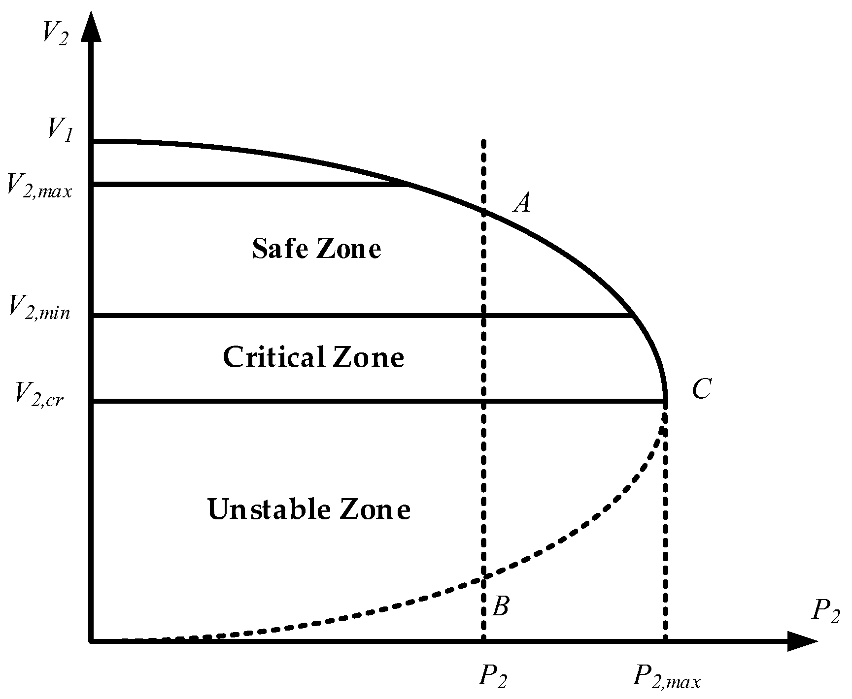
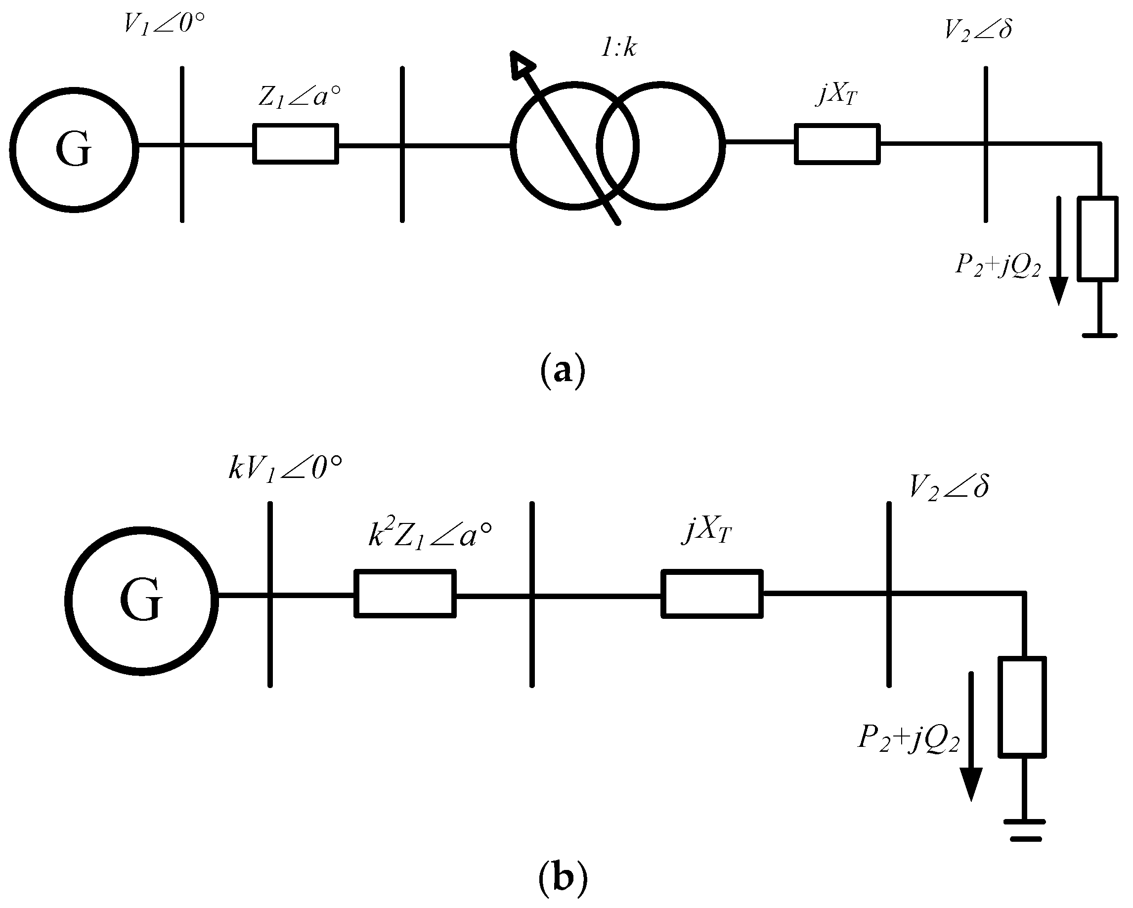
4.1. Modeling and Analysis of Voltage Stability in Power System

For a simple linear radial network of a power system, consisting of sources, transmission lines and loads, the equivalent circuit diagram and phasor diagram are shown in Figure 3. In the Figure 3, the equivalent impedance of the transmission line is Z = R + jX. The impedance angle is α. E is the grid voltage vector. V 1 = V 1 0 = E is grid voltage vector of Thevenin equivalent. V 2 = V 2 δ is the load voltage vector. P2 is the load active power, and Q2 is the load reactive power.
Consider the relationship between the two terminals of a transmission line, the relationship between V 1 and V 2 is as follows:
V 1 = V 2 + R P 2 + X Q 2 V 2 + j R P 2 X Q 2 V 2
where, R = Z cos α and X = Z sin α are the equivalent resistance and reactance of the line, respectively. V 1 is the voltage amplitude of the grid. V 2 is the load voltage amplitude. The apparent power of the load is expressed as:
S 2 = P 2 + j Q 2 = S 2 ( cos θ + j sin θ ) = V 2 I *
Considering the phasor diagram in Figure 3b, the real and imaginary parts of Equation (1) are separated, and the following results are obtained:
V 1 V 2 cos δ = V 2 2 + R P 2 + X Q 2
V 1 V 2 sin δ = X P 2 R Q 2
By square summation of Equation (3) and (4), the angle δ of Equation (3) and (4) can be eliminated, and the following can be obtained:
V 1 2 V 2 2 ( sin 2 δ + cos 2 δ ) = V 2 4 + 2 V 2 2 ( R P 2 + X Q 2 ) + ( R P 2 + X Q 2 ) 2 + ( X P 2 R Q 2 ) 2
As known,
f ( V 2 , P 2 , Q 2 ) = V 2 4 + V 2 2 2 ( R P 2 + X Q 2 ) V 1 2 + Z 2 S 2 2
where,
( R P 2 + X Q 2 ) 2 + ( X P 2 R Q 2 ) 2 = Z 2 ( P 2 2 + Q 2 2 ) = Z 2 S 2 2
Equation (6) reflects the functional relationship among V 2 , P 2 and Q 2 . Considering Q 2 = P 2 tan θ , θ is the load power factor angle, Equation (4) can be further rewritten as:
V 2 4 + V 2 2 2 ( R P 2 + X P 2 tan θ ) V 1 2 + Z 2 ( P 2 2 + P 2 2 tan 2 θ ) = 0
Make the formula true:
y = V 2 2 ;   α = V 1 2 2 ( R P 2 + X P 2 tan θ )
Δ = 2 ( R P 2 + X P 2 tan θ ) V 1 2 2 4 Z 2 ( P 2 2 + P 2 2 tan 2 θ )
The function can be obtained from Equation (8):
y 2 α y + Z 2 ( P 2 2 + P 2 2 tan 2 θ ) = 0
When the equivalent impedance Z, power factor angle θ and grid voltage V 1 are constant, the relation curve between load active power and voltage can be obtained, as shown in Figure 5.
When the load active power value is given, there may be two corresponding voltage operation points A and B:
V 2 A = α + Δ 2 ;   V 2 B = α Δ 2
The rightmost endpoint in Figure 4 is the critical point of system voltage stability C, which represents the maximum power point that can be transmitted under determined system parameter, and the active power is P2_max at this point. Below the critical point is the unstable zone of the system. Above the critical point is the stable zone of the system. When the system runs stably, the maximum and minimum allowable voltage are V2_max and V2_min. The region within this voltage range is defined as the safe zone, and the stable region below the load voltage V2_min is defined as the critical region.
It can be seen that point A in Equation (12) operates in the stable zone, and point B is the unstable point. The critical point C can also be called the static bifurcation point of the system, and its characteristic is that the Equation (12) is zero, which can be obtained as follows:
2 ( R P 2 + X P 2 tan θ ) V 1 2 2 = 4 Z 2 ( P 2 2 + P 2 2 tan 2 θ )
The critical voltage value obtained through the critical point C in Equation (11) is:
V 2 A = V 2 B = α 2 = V 1 2 2 ( R P 2 max + X P 2 max tan θ ) 2
According to Equations (13) and (14), the voltage V2_cr at the critical stability point C of the system is related to the voltage value of the power grid, the equivalent impedance of the line and the power factor of the load, and so is the maximum output active power P2_max corresponding to that point. By changing the above system parameters, the P-V curve of the load can be adjusted, and the critical stability point of the system can also be changed.

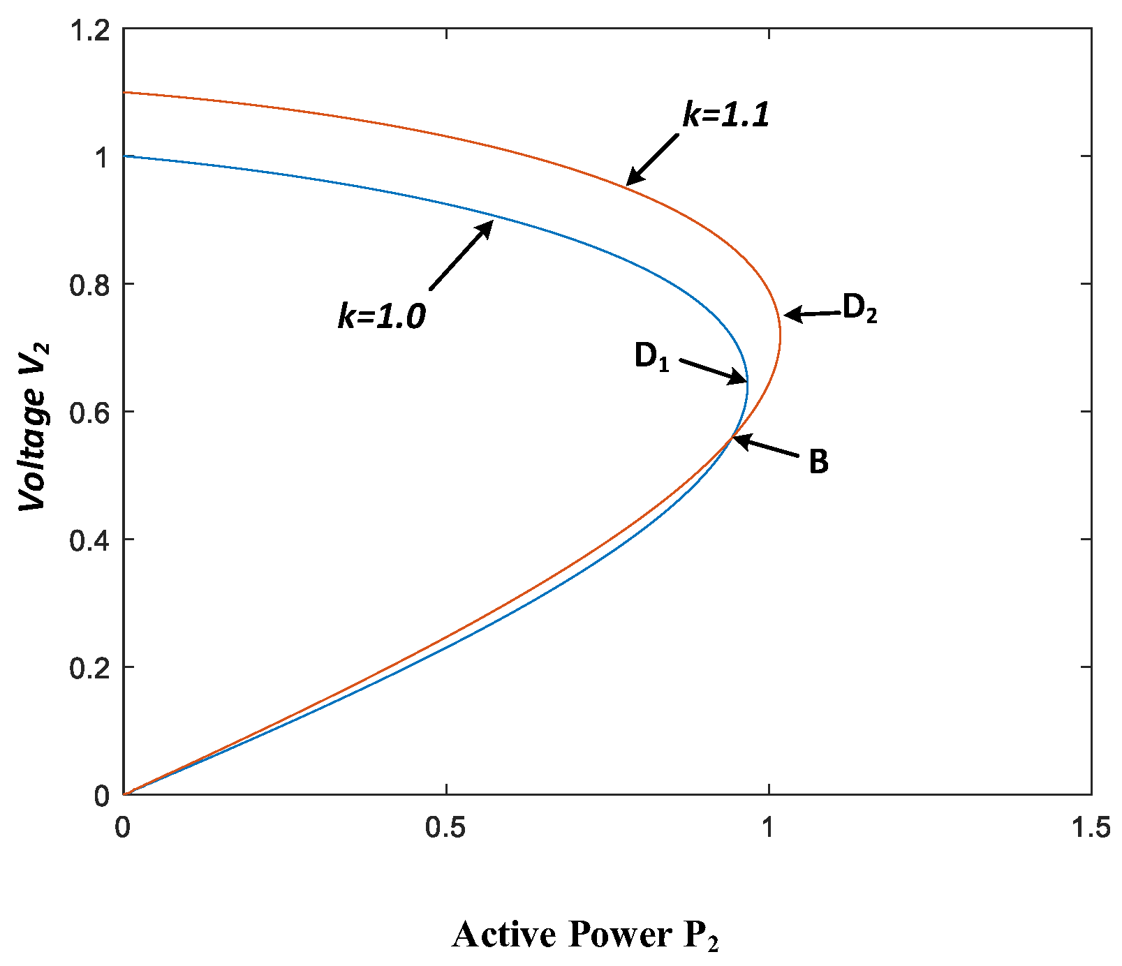
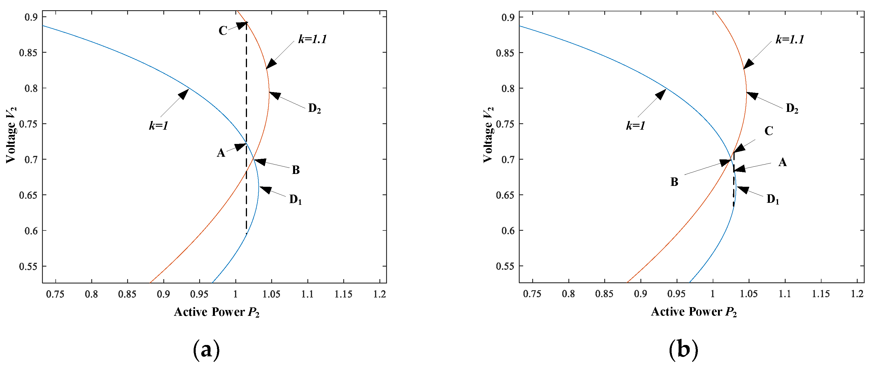
4.2. Influence of Deviation from Critical Stability Point of OLTC Transformer

The traditional OLTC transformer is step voltage regulation, and the transformer ratio can only be adjusted by a fixed tap. The simple system model with the OLTC transformer added to the distribution network is shown in Figure 5a, and the equivalent model from the load side is shown in Figure 5b.
Despite the addition of OLTC transformer, the line impedance can still be equivalent to Rs + jXs, which is translated to the load side as Z = k2Rs + jk2Xs, and the grid voltage is translated to the load side as k V 1 0 , k is the ratio of OLTC transformer. The relationship between load voltage and active power can still be expressed through Equation (8). Under the condition that the load active power and power factor remain unchanged, Equation (8) could be modified as follows:
V 2 4 + V 2 2 2 ( k 2 R P 2 + k 2 X s P 2 tan θ ) ( k V 1 ) 2 + Z 2 ( P 2 2 + P 2 2 tan 2 θ ) = 0
where Z = k 2 R + j k 2 X s , R s = R , and X s = X + X T / k 2
Assuming that load power factor, equivalent impedance of the line are cos θ = 1.0 , R = 0.04, Xs = 0.012. At the same time, the OLTC transformer before tap switches action, the ratio k1 = 1.0, and after adjustment, the ratio k2 = 1.1. The corresponding P-V curves of the system before and after adjustment of the tap switches can be calculated, as shown in Figure 6.
It can be seen from Figure 7 that the two groups of curves intersect at point B. If the transformer ratio k1 = 1.0 in the initial state of the system, the steady-state operation point A is above point B, as shown in Figure 7a. At this time, the transformer ratio needs to be increased due to the decrease of load voltage, and the ratio is changed to k2 = 1.1. Under the condition of constant load power, the new steady-state operation point intersects the new P-V curve at point C. The Figure 7a shows that point C can be known to be in the upper half of the new P-V curve, and the system can work stably, so as to realize the load voltage rise regulation.
If the initial steady-state operation point t A is below the intersection point B, as shown in Figure 7b. Similarly, when the tap switches is operated, the new intersection point C is located in the lower half of the new P-V curve under the condition of constant load power. It means the power system operates in the unstable zone, and even voltage instability is caused.
It can be seen that the critical stability point may be shifted when the tap switches of the OLTC transformer is changed, and the intersection point B of the two P-V curves becomes the new critical stability point.
If the intersection point B is below the critical point D1 of the original P-V curve, as shown in Figure 6. In this case, the stability zone of the whole system increases when the transformer spline acts to regulate the voltage, and there is a “positive voltage regulating effect”. On the contrary, the intersection point B of the two P-V curves is above the critical point D1 of the original P-V curve, the static stability region of the system will be reduced, as shown in Figure 7. In this case, the OLTC transformer will have “negative adjustment effect”.
The intersection of the OLTC transformer before and after adjusting the ratio can be solved by the analytical formula. By substituting k1 and k2 into Equation (13), and considering simplified calculation, assuming that the resistance of line R = 0 and the power factor cos θ = 1.0 , the intersection expression of the OLTC transformer can be obtained as follows:
V 2 B = V 1 ( k 1 k 2 X ) 2 X T 2 [ ( k 1 2 + k 2 2 ) X + 2 X T ] X
P 2 B = V 2 B k 1 V 1 2 V 2 B 2 k 1 2 X + X T
where V2B and P2B are the voltage and active power value corresponding to the intersection point, which can also be called the deviation critical point. According to Equation (16), when k 1 k 2 X > X T is satisfied, the deviation critical point exists. From the above equations, the influence of parameters such as voltage regulation ratio and line impedance on the deviation critical point has been concluded [23,24,25], which can be summarized as follows:
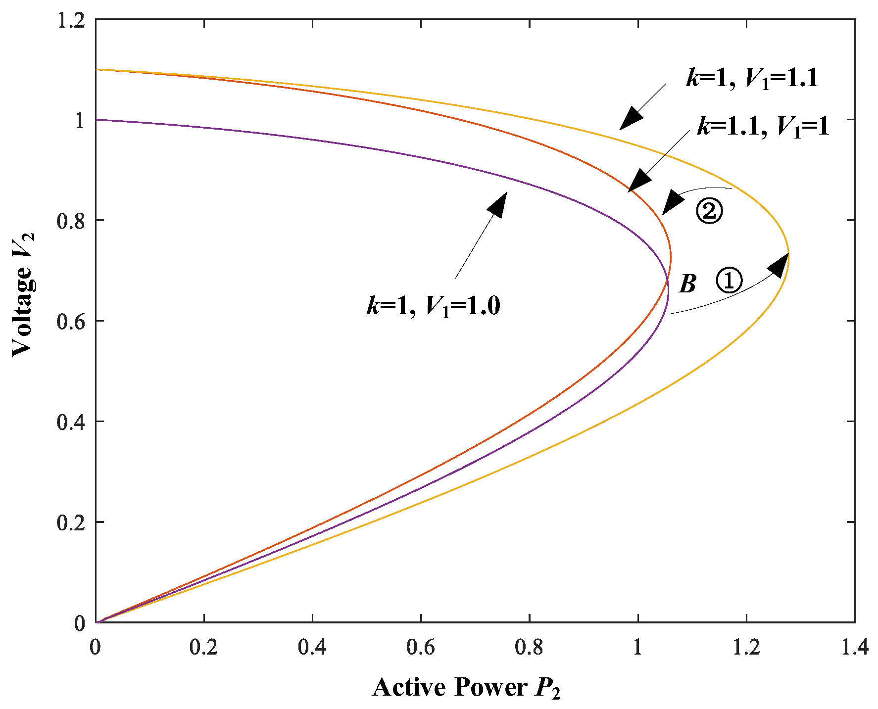
  • The larger the value between voltage regulating tap, in other words, the larger the difference between k1 and k2, the bigger the deviation of negative adjustment effect above the critical voltage stability point. It means the voltage stability zone of the power system become smaller, and the system is to generate voltage instability easily in the process of voltage regulating.
  • The greater the capacity, the greater the influence of the switch adjustment on the voltage stability. Thus the “negative adjustment effect” is less likely to occur in the small capacity on-load voltage regulation.
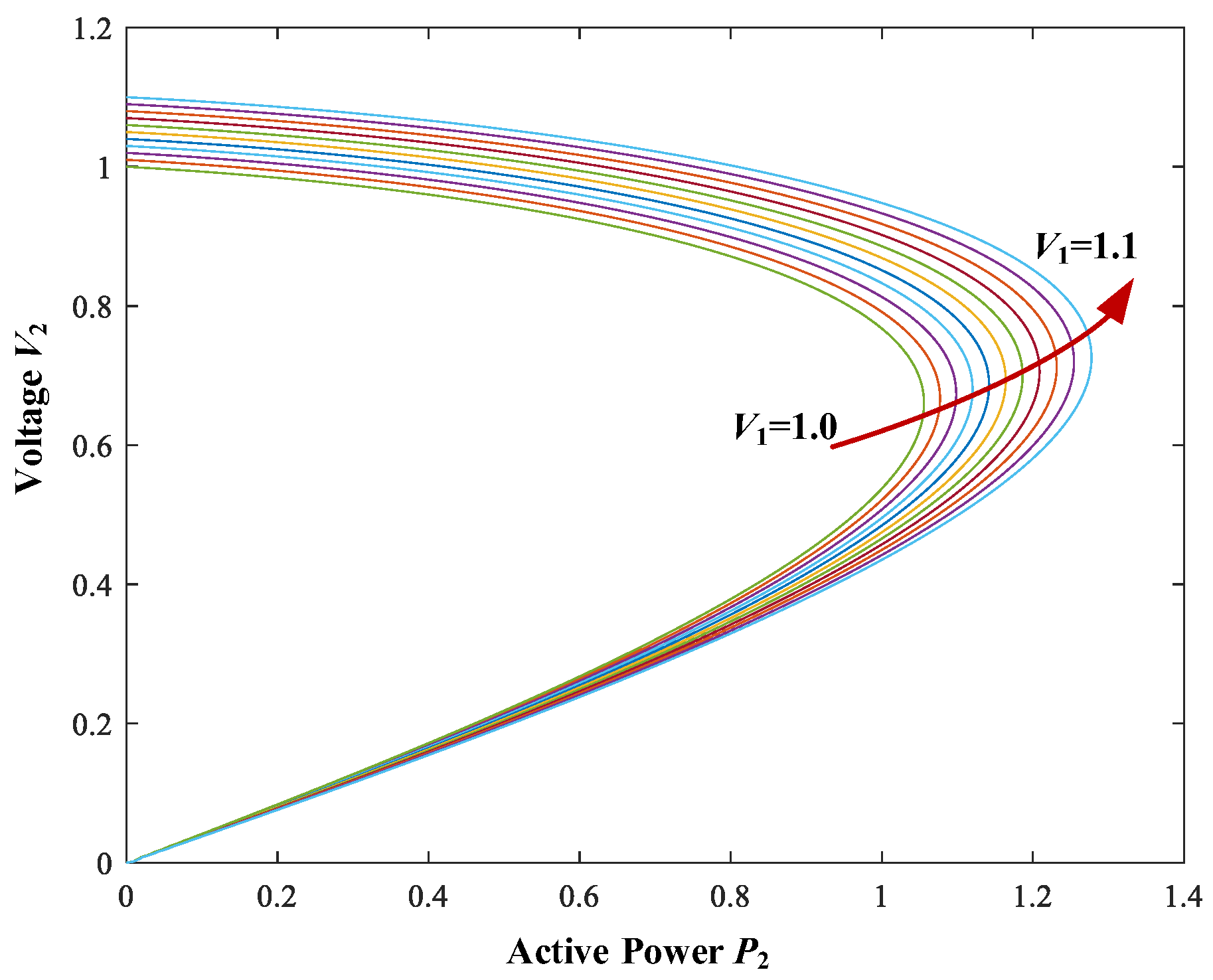
  • Under the condition of short-distance transmission, the process of voltage regulating can make the intersection point of P-V curve under the static critical point, and increase the static stable zone. Even if the operating point falls below the critical voltage stable point, it can still be restored to the stable state if the variable ratio can be adjusted quickly.
According to Equations (15) and (16), the stable critical point of “negative voltage regulation effect” offset is related to the grid voltage V1 and the load power factor angle θ. Meanwhile the stable operating zone of the system can be changed by adjusting the power factor or the grid voltage V1 under the condition that the line impedance parameter is unchanged.

5. Study on the Voltage Stability of Flexible OLVR Transformer

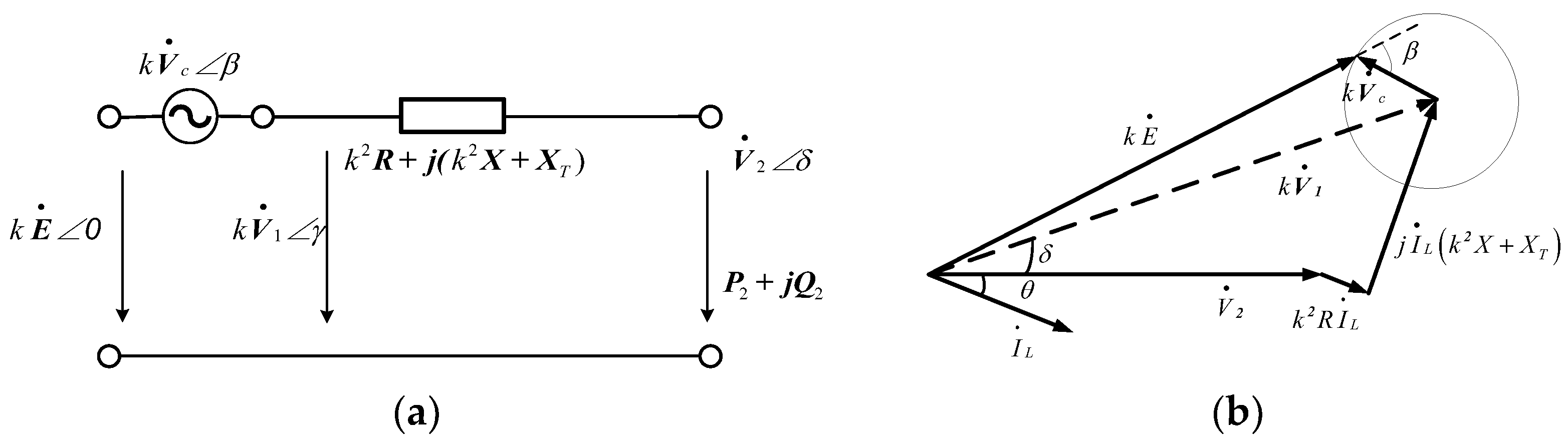
5.1. Voltage Stability Model of Flexible OLVR Transformer Based on Controllable Voltage Source Equivalent

From the above description, it can be seen that the Flexible OLVR transformer can realize the continuous adjustment of load voltage through step and step-less voltage regulating.
Step voltage regulation is equivalent to adjusting the transformer ratio k, and step-less voltage regulation is equivalent to adjusting the amplitude and phase angle of the equivalent voltage vector at primary side of transformer. The Equivalent circuit and phasor diagram is shown in Figure 8.
In the Figure 8b, E is the grid voltage vector. V c is the compensation voltage vector. V 1 is the grid voltage vector of Thevenin equivalent circuit. V 2 is the load voltage vector. I L is the load current vector. R and X are the equivalent resistance and reactance of the line, respectively, and X T is the equivalent impedance of the Flexible OLVR transformer. Angle θ is the load impedance angle, and angle δ is the angle between the vector V 1 and the load voltage vector V 2 .
By adjusting the output voltage of the PEC, the vector V 1 amplitude and phase angle can be changed optionally. For example, assuming that the variation of the each tap in a step voltage regulation is 10%, and per-unit value of load voltage is expected to be adjusted form the 1.0 p.u. to 1.1 p.u. In this process of voltage regulation, the control instruction of compensation voltage V c is raised in a ramp firstly. Considering that the phase angle of V c is in phase with the grid voltage vector E , the amplitude of V c is increased gradually from 0 p.u. to 0.1 p.u. Secondly, when the V 1 voltage amplitude reaches 1.1 p.u., the output voltage of the PEC is changed to zero. Then, by adjusting the transformer ratio k from 1 to 1.1, the load voltage can be continuously variable in the voltage regulation process.
Figure 9 shows P-V curves of the step-less voltage regulation process with Flexible OLVR transformer, the different color lines represent P-V curves with V 1 voltage amplitudes increasing at 0.1 p.u. It can be seen that with the gradual increase of V 1 value, the amplitude of load voltage also gradually rises under the condition of constant load power. At the same time, the stable critical point of the system is gradually shifted to the right, which means the safe zone increases, and the active power that the system can transmit increases. As can be seen from the Figure 9, when other parameters remain unchanged, the P-V curves under different values of V 1 have no intersection point, that is, there is no stable critical point shift problem, so the continuous voltage regulation process of power electronic devices will not produce “negative adjustment effect”.
According to Equation (15), it can be seen that changing the angle δ between the Thevenin equivalent voltage vector V 1 and the load voltage vector V 2 does not affect the P-V curve, while changing the amplitude of V 1 can change the P-V curve. Therefore, the Flexible OLVR transformer can continuously adjust the amplitude of V 1 in a certain range, so as to realize the continuous and reliable step-less voltage regulating of the load voltage amplitude, which is also an important significance of the application of the Flexible OLVR transformer.
Figure 9 shows the characteristics of the safe zone under the step-less voltage regulation in the first step of voltage regulation process. The step voltage regulation requires the tap switches action of the Flexible OLVR transformer, and the output voltage of the PEC is zero to ensure that the kV1 amplitude remains unchanged. The P-V curve corresponding to the above two processes can be shown in Figure 10. It can be seen that the safe zone is reduced due to the decrease of V1 amplitude. Although the transformer ratio k is increased, the overall safe working zone of the system is reduced.
In Figure 10, the first move in the voltage regulating process of Flexible OLVR transformer is step-less voltage regulation, namely, k = 1, V1 = 1.0 is gradually adjusted to k = 1, V1 = 1.1, as shown in ① process. Thus, the second move rapidly drops from k = 1, V1 = 1.1 to k = 1.1, V1 = 1.0, as shown in ② process.
In the traditional OLTC transformer, voltage regulation is performed by adjusting tap switches, that means the voltage is regulated from the difference value of k = 1, V1 = 1.0 to k = 1.1, V1 = 1.0. Thus, the intersection point B of the two P-V curves still exists, and the deviation critical point will still be less than the stable critical point of the curve k = 1, V1 = 1.0, thus “negative adjustment effect” may occur.
However, in the voltage regulating process ② of Flexible OLVR transformer, it make the stability critical point of P-V curve contraction by tap switches action, however there is no curve intersection. Meanwhile, under the condition of load active power unchanged, compared with the traditional voltage regulation of OLTC transformer, even if the voltage stability zone is reduced in the process ② of step regulation, there still is no “negative adjustment effect”. On the contrary, the voltage stable zone of the system can be greatly increased by changing the amplitude of V1 by step-less voltage regulation.
Flexible OLVR transformer not only can realize the flexible control of load voltage by series converter of PEC, also can use parallel converter to provide reactive power compensation. The reactive power compensation also can improve system voltage stability operation zone, which could reduce another reactive power compensation device capacity in the power system, even does not need additional reactive power compensation device.
Figure 11 shows the P-V curves under different power factors. Increasing the capacitive reactive power can also effectively increase the safe operation zone of the system and further reflect the advantages of the Flexible OLVR transformer in voltage stability.

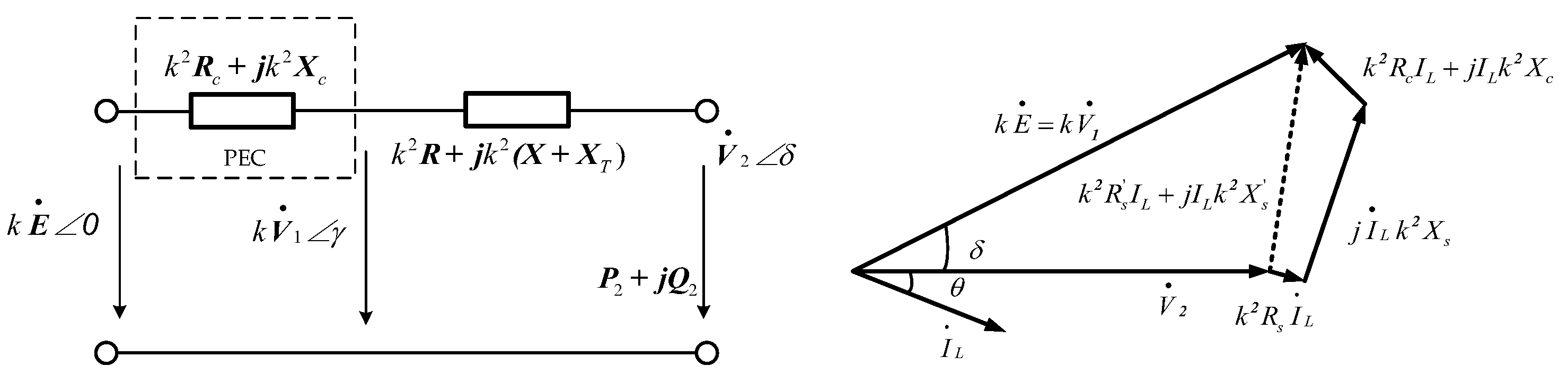
5.2. Voltage Stability Model of Flexible OLVR Transformer Based on Controllable Impedance Equivalent

In the above paper, the PEC of the Flexible OLVR transformer is regarded as a controllable voltage source to be brought into the power system for an equivalent circuit. Then the voltage stability is analyzed based on this model.
The voltage stability model above is derived based on the Thevenin equivalent voltage V1. In other words, the grid voltage vector E is in phase with the Thevenin equivalent voltage vector V 1 . However, when PEC of Flexible OLVR transformer only operates as a phase shift voltage source. If the voltage stability problem of the system is still analyzed according to the above model, Equation (13) does not reflect the above phase angle relationship, so that the above model is not quite suitable to explain the situation.
Therefore, the PEC is treated as a controlled impedance for analysis in the following. The controllable impedance is equivalently obtained by orienting the output voltage vector V c of the PEC based on the direction of the load current vector I 2 . Figure 12 shows the equivalent circuit and phasor diagram of Flexible OLVR transformer based on controllable impedance equivalent.
It can be known that the quotient value of the compensation voltage vector V c and the load current vector I 2 in the same direction is the resistance value Rc of the controllable impedance, and the quantity orthogonal to the direction of the load current vector is the inductance value Xc of the controllable impedance, The equation is as follows:
Z c = R c + j X c = k V c d I 2 + j k V c q I 2
According to Equation (15), the above model can be summarized as,
V 2 4 + V 2 2 2 ( k 2 R P 2 + k 2 X P 2 tan θ ) ( k E ) 2 + Z 2 ( P 2 2 + P 2 2 tan 2 θ ) = 0
where Z = R + j X = k 2 ( R s + R c ) + j k 2 ( X s + X c ) .
As can be seen from the Equation (18), when the phase angle of the output voltage vector V c of the PEC changes, the impedance angle of the equivalent impedance can be considered to change. According to Equation (19), the load P-V curve of the system is related to the value of equivalent impedance Zc.
The characteristic equation in Equation (19) is,
Δ = 2 ( R s P 2 + X s P 2 tan θ ) + 2 ( R c P 2 + X c P 2 tan θ ) E 2 2               4 [ Z 2 + R c ( R c + 2 R s ) + X c ( X c + 2 X s ) ] ( P 2 2 + P 2 2 tan 2 θ )
If the description of the above two voltage stability models can be equivalent, that means the equivalent impedance Zc should have a real solution, which make the PEC before and after compensated and the P-V curve of power system be the same.
It can be obtained by comparing Equations (10) and (20):
R c P 2 + X c P 2 tan θ = 0 R c ( 2 R s + R c ) + X c ( 2 X s + X c ) = 0
The above formulaic simplification can be obtained:
R c = X c tan θ X c [ X c ( 1 + tan 2 θ ) + 2 ( X s R s tan θ ) ] = 0
According to Equation (22), it can be seen that there are two real solutions. Therefore, it can be known that there is at least one set of controllable impedance values, which can make the P-V curve of the load in the system unchanged after compensation. It is also proved that the two voltage stability models with Flexible OLVR transformers are equivalent.

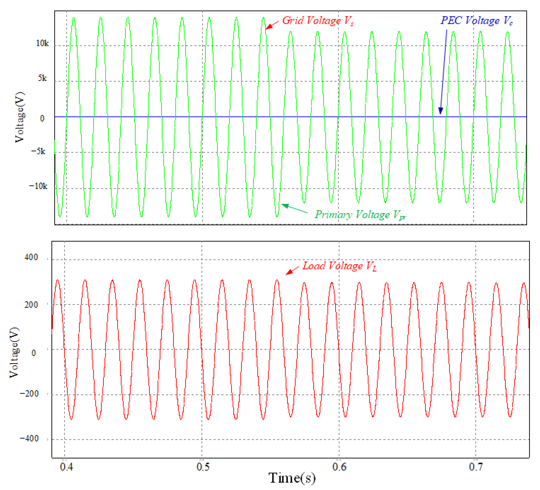
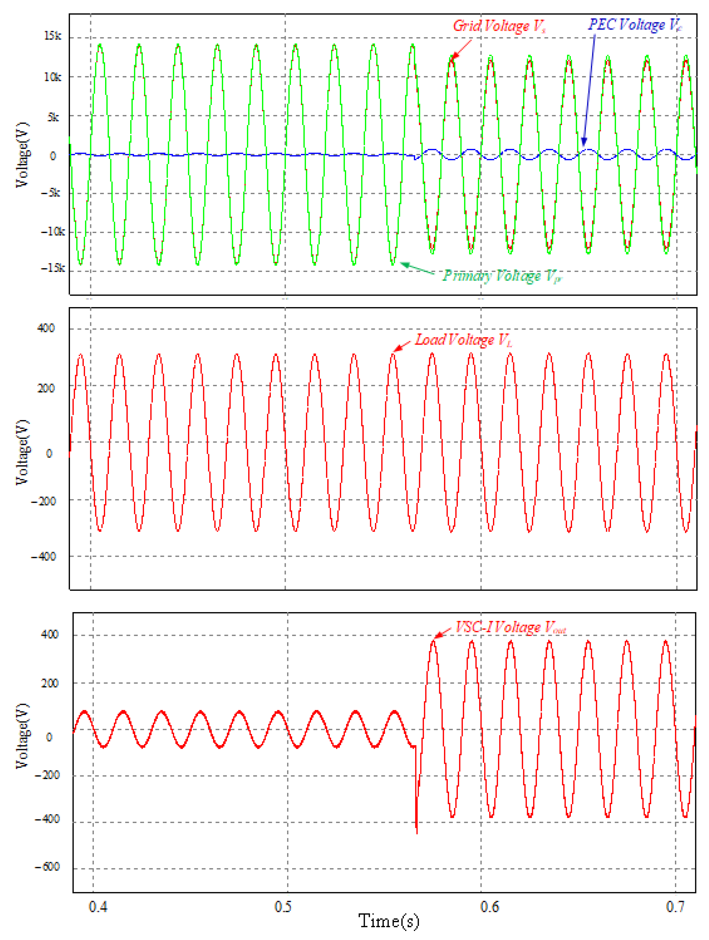
6. Simulation Results

In this paper, the Flexible OLVR simulation is built in Psim software. The Flexible OLVR is a 10 kV/0.4 kV three-phase step-down transformer. The tap windings have 8 windings with 5% voltage regulation step. The voltage-regulating range is achieved ±20% by series connection with the main winding. The PEC is connected to the primary side of the transformer in series through an isolation transformer, and the simulation time is set to 1 s. The OLTC Switch consisting of thyristor triggers [26] at the current zero-crossing point, and the PEC also joins up at the same time.
When the grid voltage sags begin, that is, 0.99 p.u falls to 0.9 p.u, if only the tap winding of Flexible OLVR is changed. Meanwhile the tap switches are changed at 0.56 s, that make the primary winding is changed from 100% to 95%, and the process of the change of the primary voltage and the secondary side load voltage is shown in Figure 13.
On the other way, when the voltage of the grid sags at 0.56 s, the Flexible OLVR Trans former changes tap switches, and at the same time the PEC begin operating, and makes the output voltage of PEC in phase with the primary voltage. Figure 14 shows the variation of primary voltage, the secondary side load voltage and compensation voltage of PEC in Flexible OLVR transformer.
The simulation verifies the feasibility of combining the traditional OLTC transformer with the PEC. Connecting the output of the PEC to the primary side circuit can carry out a certain range of voltage compensation after the traditional step voltage regulation, and also make the voltage regulation process more flexible and accurate.

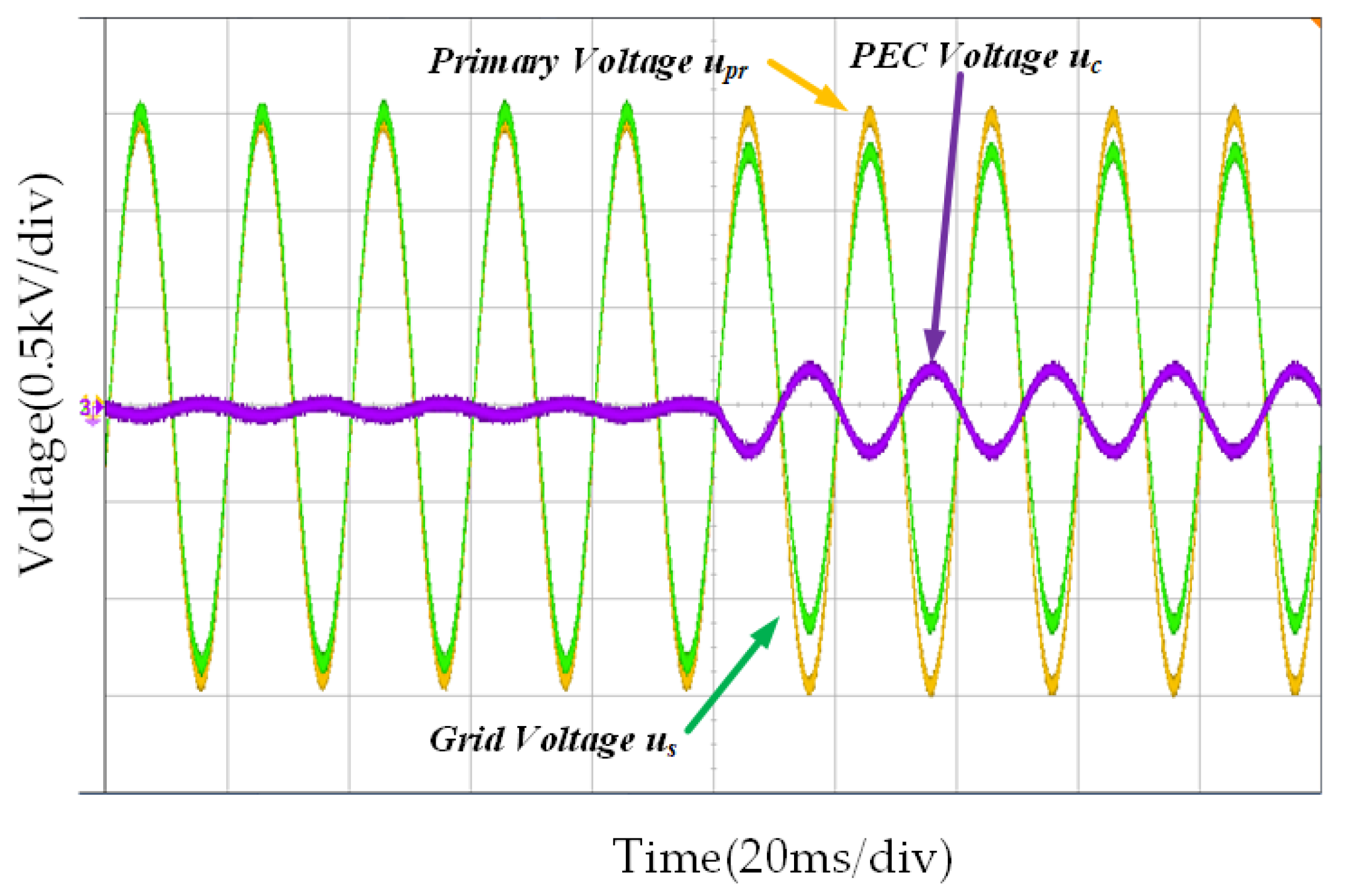
7. Experiment Results

The proposed Flexible OLVR was established in our laboratory according to the topology shown in Figure 1, and a scaled-down test system was constructed to verify the effectiveness of the proposed Flexible OLVR. The parameters of the test circuit are listed in Table 2.
Figure 15 shows the waveform diagram of transient step-less voltage regulation with flexible OLVR. When the grid voltage falls from 1 p.u. to 0.85 p.u., the PEC of the Flexible OLVR transformer outputs the in-phase compensation voltage, which compensates the voltage at the primary side of the transformer to the rated voltage value, thus realizing step-less voltage regulation.

8. Conclusions

This paper presents a Flexible OLVR transformer topology based on PEC. Due to the application of power electronic converter, the new OLVR transformer has the function of flexible regulation of output load voltage.
Through coordination with tap switches, the converter could only modulate small part of the rating voltage to realize step-less voltage regulation. Compared with traditional OLTC transformer, it is more accurate in voltage regulation, and it is lower in cost and higher in efficiency than power electronic converter. The simulation and experiment results show that the Flexible OLVR transformer model proposed in this paper can achieve accurate step-less voltage regulation.
The paper presents two voltage stability equivalent model of distribution network with Flexible OLVR transformer and analyzes the critical operating point. It is also proved that the two models with Flexible OLVR transformers are equivalent by calculation. Through the step-less voltage regulation control of the Flexible OLVR transformer, the negative voltage regulation effect of the transformer in on-load voltage regulation is avoided, and the voltage stability of the distribution network is improved.

Author Contributions

L.H. conceived and designed the study. J.Y., T.W. and L.W. given suggestions, L.S. revised the manuscript. All authors have read and agreed to the published version of the manuscript.

Funding

This research work was funded by Foundation of the Institute of Electrical Engineering, CAS (E155610201) and Youth Innovation Promotion Association, CAS (2020144).

Conflicts of Interest

The authors declare no conflict of interest.

Nomenclature

Symbol and Constant
L0Main Winding of the OLVR Transformers
LpoPower winding at the primary side of the OLVR transformer
LxRegulating tap windings of the OLVR transformer
KxOn-load tap-chargers of Flexible OLVR
L1Filter inductor of parallel converter of PEC
L2Filter inductor of series converter of PEC
C0Filter capacitor of series converter of PEC
CDCDC bus capacitor of PEC
T0Isolation transformer of PEC
Variable and Function
usVoltage of the power grid
uwiVoltage at the primary side of the OLVR transformer
ucCompensation voltage of the PEC
uLLoad voltage at the secondary side of the OLVR transformer
KOLVR transformation ratio
E Grid voltage vector
V 1 Grid voltage vector of Thevenin equivalent
V 2 Load voltage vector
I 2 Load current vector
V c Compensation voltage vector
S2Apparent power of the load
P2Load active power
Q2Load reactive power
ZsEquivalent impedance of the transmission line
RsEquivalent resistance of the transmission line
XsEquivalent reactance of the transmission line
XTEquivalent reactance of the transformer
V 1 Grid voltage amplitude
V 2 Load voltage amplitude
δ Angle between the vector V 1 and the load voltage vector V 2
ΘPower factor angle of the resistive-inductive load
ZcComplex equivalent controllable impedance of PEC
RcActive equivalent controllable impedance of PEC
XcReactive equivalent controllable impedance of PEC
OLTCOn-Load Tap-Charger
OLVROn-Load Voltage Regulation
PECPower Electronic Converter
VSCVoltage Source Converter
IGBTInsulated Gate Bipolar Transistors

References

  1. Sun, H.; Guo, Q.; Qi, J.; Ajjarapu, V.; Bravo, R.; Chow, J.; Li, Z.; Moghe, R.; Nasr-Azadani, E.; Tamrakar, U.; et al. Review of Challenges and Research Opportunities for Voltage Control in Smart Grids. IEEE Trans. Power Syst. 2019, 34, 2790–2801. [Google Scholar] [CrossRef]
  2. Wang, G.L. A survey on effect of on-load tap changer on the voltage stability. Relay 2008, 36, 79–84. (In Chinese) [Google Scholar]
  3. Singh, P.; Bishnoi, S.K.; Meena, N.K. Moth Search Optimization for Optimal DERs Integration in Conjunction to OLTC Tap Operations in Distribution Systems. IEEE Syst. J. 2019, 14, 880–888. [Google Scholar] [CrossRef]
  4. Nouri, A.; Soroudi, A.; Keane, A. Strategic Scheduling of Discrete Control Devices in Active Distribution Systems. IEEE Trans. Power Deliv. 2020, 35, 2285–2299. [Google Scholar] [CrossRef]
  5. Pouladi, A.; Zadeh, A.K.; Nouri, A. Control of Parallel ULTC Transformers in Active Distribution Systems. IEEE Syst. J. 2019, 14, 960–970. [Google Scholar] [CrossRef]
  6. Ahmadinia, M.; Ghazi, R. Coordinated Control of STATCOM and ULTC to Reduce Capacity of STATCOM. In Proceedings of the Electrical Engineering (ICEE), Iranian Conference, Mashhad, Iran, 8–10 May 2018; pp. 1062–1066. [Google Scholar] [CrossRef]
  7. Cai, X.; Huang, Q.; Zhou, X.; Zhu, Y.; Sun, S.; Zhu, J. Multi-objective Dynamic Reactive Power Optimization Based on OLTC and Reactive Power Compensation. In Proceedings of the 2022 4th Asia Energy and Electrical Engineering Symposium (AEEES), Chengdu, China, 25–28 March 2022; pp. 825–831. [Google Scholar] [CrossRef]
  8. Huber, J.E.; Kolar, J.W. Applicability of Solid-State Transformers in Today’s and Future Distribution Grids. IEEE Trans. Smart Grid 2017, 10, 317–326. [Google Scholar] [CrossRef]
  9. Bhatt, P.K.; Kaushik, R. Intelligent Transformer Tap Controller for Harmonic Elimination in Hybrid Distribution Network. In Proceedings of the 2021 5th International Conference on Electronics, Communication and Aerospace Technology, Coimbatore, India, 2–4 December 2021; pp. 219–225. [Google Scholar] [CrossRef]
  10. Power, R.; Mithani, A.; Madawala, U.; Baguley, C. A Hybrid Transformer Topology for Distribution Network Voltage Regulation. In Proceedings of the 2021 IEEE Southern Power Electronics Conference (SPEC), Kigali, Rwanda, 6–9 December 2021; pp. 1–6. [Google Scholar] [CrossRef]
  11. Khokhlov, Y.I.; Safonov, V.I.; Lonzinger, P.V. Electromagnetic processes in power transformers with vector control. Russ. Electr. Eng. 2016, 87, 145–149. [Google Scholar] [CrossRef]
  12. Burkard, J.; Biela, J. Protection of hybrid transformers in the distribution grid. In Proceedings of the 2016 18th European Conference on Power Electronics and Applications (EPE’16 ECCE Europe), Karlsruhe, Germany, 5–9 September 2016; pp. 1–10. [Google Scholar]
  13. Kawabe, K.; Tanaka, K. Analytical Method for Short-Term Voltage Stability Using the Stability Boundary in the P-V Plane. IEEE Trans. Power Syst. 2014, 29, 3041–3047. [Google Scholar] [CrossRef]
  14. Dong, Y.; Xie, X.; Zhou, B.; Shi, W.; Jiang, Q. An Integrated High Side Var-Voltage Control Strategy to Improve Short-Term Voltage Stability of Receiving-End Power Systems. IEEE Trans. Power Syst. 2015, 31, 2105–2115. [Google Scholar] [CrossRef]
  15. Luo, J.; Teng, F.; Bu, S. Stability-Constrained Power System Scheduling: A Review. IEEE Access 2020, 8, 219331–219343. [Google Scholar] [CrossRef]
  16. Liang, X.; Shabbir, N.S.K.; Khan, N.; Yan, X. Measurement-Based Characteristic Curves for Voltage Stability and Control at the Point of Interconnection of Wind Power Plants. Can. J. Electr. Comput. Eng. 2019, 42, 163–172. [Google Scholar] [CrossRef]
  17. Hala, T.; Drapela, J. On Stabilization of Voltage in LV Distribution System Employing MV/LV OL TC Transformer with Control Based on Smart Metering. In Proceedings of the 2019 20th International Scientific Conference on Electric Power Engineering (EPE), Kouty nad Desnou, Czech Republic, 15–17 May 2019; pp. 1–6. [Google Scholar] [CrossRef]
  18. Zhu, Y.; Liu, G. Fast Calculation Method for Saddle Node Bifurcation Point of Voltage Stability of Power System. Proc. CSU-EPSA 2017, 29, 86–92. (In Chinese) [Google Scholar]
  19. Liu, X.; Niu, X.; Zhu, Y.; Zhu, C. Influence of regulation of OLTC transformation ratio on voltage stability. In Proceedings of the 2013 Fourth International Conference on Digital Manufacturing & Automation, Shinan, China, 29–30 June 2013; pp. 696–700. [Google Scholar]
  20. Dallmer-Zerbe, K.; Berardo, D.; Salman, A.; Wille-Haussmann, B. Small-disturbance voltage stability of OLTC & decentralized reactive power droop control. In Proceedings of the 2016 IEEE International Energy Conference (ENERGYCON), Leuven, Belgium, 4–8 April 2016. [Google Scholar] [CrossRef]
  21. Mahendar, G.; Yesuratnam, G. An approach to identify critical on load tap changing (OLTC) transformers under network contingencies. In Proceedings of the 2016 IEEE 7th Power India International Conference (PIICON), Bikaner, India, 25–27 November 2016; pp. 1–6. [Google Scholar] [CrossRef]
  22. Li, G.; Liu, G.; Hou, L. Quantitative evaluation method of voltage stability affected by multi-OLTC coordination. Electr. Power Autom. Equip. 2019, 39, 154–160. (In Chinese) [Google Scholar]
  23. Wang, H.; Luan, J. Summary of power electronic evolution of transformer and its influence on voltage stability. Power Syst. Prot. Control. 2020, 48, 171–192. (In Chinese) [Google Scholar]
  24. Zou, Z.; Zhao, J.; Chang, H.; Wang, C.; Liu, F.; Li, W.; Fang, B. Short-Term Voltage Stability Constrained Two-Stage Dynamic Optimal Reactive Power Flow. In Proceedings of the 4th Conference on Energy Internet and Energy System Integration, Wuhan, China, 15 February 2021; pp. 2219–2223. [Google Scholar] [CrossRef]
  25. Nassaj, A.; Shahrtash, S.M. Prevention of voltage instability by adaptive determination of tap position in OLTCs. In Proceedings of the 2017 Iranian Conference on Electrical Engineering, Tehran, Iran, 2–4 May 2017; pp. 980–985. [Google Scholar] [CrossRef]
  26. Cai, H.; Guo, Y.; Chen, W. Design of a Soft-Switching System Based on Single-Phase Grid-Connected Inverter. Trans. China Electrotech. Soc. 2016, 31, 63–69. (In Chinese) [Google Scholar]
Figure 1. Single-phase topology structure of Flexible OLVR Transformer.
Energies 15 06189 g001
Figure 2. Voltage vector relationship of Flexible OLVR (a) The same direction compensation scheme (b) The reverse direction compensation scheme (c) Arbitrary direction compensation scheme.
Energies 15 06189 g002
Figure 3. Equivalent circuit and phasor diagram of simple linear network in power system. (a) The Equivalent Circuit of simple linear network (b) The Phasor Diagram of simple linear network in power system.
Energies 15 06189 g003
Figure 4. The load P-V curve of simple power system. Point A in is the stable operation point, and point B is the unstable point, Point C is the critical point of system.
Energies 15 06189 g004
Figure 5. Simple system model and equivalent model with OLTC transformer. (a) The Simple Circuit of a power system with OLTC transformer (b) The Equivalent model with OLTC transformer.
Energies 15 06189 g005
Figure 6. Positive voltage regulating effect of OLTC transformer. Point B is the intersection of the two P-V curves.
Energies 15 06189 g006
Figure 7. Deviation effect of critical operating point of OLTC transformer. (a) Positive adjustment; (b) Negative adjustment. Point A is initial operating point. Point B is the intersection of two P-V curves. Point C is operating point after OLTC action.
Energies 15 06189 g007
Figure 8. Equivalent circuit and phasor diagram of power system with Flexible OLVR transformer. (a) The equivalent circuit of power system with Flexible OLVR transformer; (b) The phasor diagram of power system with Flexible OLVR transformer.
Energies 15 06189 g008
Figure 9. P-V curve of step-less voltage regulation process with Flexible OLVR transformer.
Energies 15 06189 g009
Figure 10. P-V curve of step and step-less voltage regulation with Flexible OLVR transformer. Point B is the intersection of two P-V curves.
Energies 15 06189 g010
Figure 11. The P-V curves under different power factors.
Energies 15 06189 g011
Figure 12. Equivalent circuit and phasor diagram of Flexible OLVR transformer based on controllable impedance equivalent.
Energies 15 06189 g012
Figure 13. Voltage waveforms during voltage regulation with OLTC Switch.
Energies 15 06189 g013
Figure 14. Voltage Waveforms during voltage regulation with Flexible OLVR.
Energies 15 06189 g014
Figure 15. Waveform diagram of step-less voltage regulation with Flexible OLVR.
Energies 15 06189 g015
Table 1. Performance comparison table of the proposed structure and existing schemes.
TopologyVoltage RegulationCostControl StrategyResponse TimeLossReactive Compensation
OLTC TransformerStepLowSimpleSlowLowIncapacity
Solid State TransformerStep-lessHighestComplexFastHighestFull Capacity
Hybrid TransformerStep-lessHigherComplexMediumHigherPart of Capacity
Flexible OLVRStep-lessMediumMediumMediumMediumPart of Capacity
Table 2. Major parameters of experiment circuit.
ParametersParametersValue
Primary Voltageus1 kV
Secondary VoltageuL0.4 kV
Rated transformer ratiok00.4
Step Voltage Regulation tapLx5%
Deviation Scale Factorμ80–120%
Maximum output voltage of PECuc100 V
Switching Frequencyfpwm10 kHz
Load parameterZload10 Ω + 10 mH
Publisher’s Note: MDPI stays neutral with regard to jurisdictional claims in published maps and institutional affiliations.

