Article

Miscibility of Aviation Turbine Engine Fuels Containing Various Synthetic Components

by
Urszula Kaźmierczak
,
Wojciech Dzięgielewski
and
Andrzej Kulczycki
*
Air Force Institute of Technology, ul. Księcia Bolesława 6, 01-494 Warsaw, Poland
*
Author to whom correspondence should be addressed.
Energies 2022, 15(17), 6187; https://doi.org/10.3390/en15176187
Submission received: 12 July 2022 / Revised: 22 August 2022 / Accepted: 22 August 2022 / Published: 25 August 2022

Abstract

:
This article reviews a study of the impact of synthetic biocomponents on the operational properties of aviation turbine engine fuels. The objective of the research was to simulate the functioning of aircraft fuel supply systems during the popularization of synthetic components and to provide a preliminary study of the impact of particles of various synthetic components on processes within aviation turbine engine fuel systems—particularly the aviation turbine engine combustion system. The authors produced Jet A-1 fuel blends with two selected synthetic components A and B, accepted as per the ASTM D4054 procedure. The concentrations of each of the components were selected to simulate fuel compositions in an aircraft tank that could result from supplying fuel with different synthetic components. Such blends were studied using selected laboratory tests, lubricity using the BOCLE rig and an engine test using the MiniJetRig stand. The parameters of the following power functions were adopted as criteria for a comparison of the combustion process involving fuels of various chemical structure: CO = amfn and (T3max − T2)/(T3min − T2) = a11mfn1, where CO—carbon monoxide content in exhaust gas; T3max—maximum combustion chamber temperature; T3min—minimum combustion chamber temperature; T2—temperature upstream the combustion chamber; mf—fuel mass flow rate. The test results for blends containing both synthetic components A and B were compared with change trends of similar parameters in fuels containing single synthetic components. Hard-to-predict and hard-to-define trend line deviations for the blends of both components A and B were observed. The obtained research results indicated a need to study the miscibility of fuels containing various synthetic components and to improve miscibility research methodologies.

1. Introduction

The development of aviation leads to increased atmospheric emissions of CO2 and other exhaust gas components. Therefore, including aviation in the GHG emission reduction program was deemed necessary in recent years [1,2,3]. Following the example of land, especially road transport, it was decided that an effective method would be to introduce biofuels, with adopted “zero” CO2 emissions at the stage of combustion in an aviation turbine engine.
The particular requirements of aviation determined by safety reasons that engines and engine fuels must face lead to attempting a number of studies on new technologies relative to biofuels intended for supplying aviation turbine engines. These are the “drop-in” fuels, which are, similarly to the mineral Jet A-1 fuel, a blend of hydrocarbons, and they do not require changing the design of engines and fuel-distribution systems. The outcome of that research includes seven technologies, the products of which were approved for use as aviation fuel components [1,2,3,4].
For safety reasons, introducing a new engine fuel components requires approval by both engine and aircraft manufacturers. A new system for the approval of new aviation turbine engine fuel components has been developed, which constitutes the ASTM D4054 standard [5]. This standard reviews the certification procedure for synthetic components of aviation turbine engine fuels; however, it does not provide details on the methodologies of tests conducted at individual certification stages. Certification is aimed at significantly mitigating the risk arising from a hydrocarbon composition of a synthetic component different to that of petroleum fuel.
The certification procedure set out in the ASTM D4054 standard follows the principle that each fuel containing a synthetic component is tested separately. Certification tests are then conducted using a synthetic component manufactured in a single manufacturing plant, following a specific technology, e.g., Hydroprocessed Esters and Fatty Acids (HEFA), using a biomass raw material specific to this plant.
The current approval system for new types of aviation turbine engine fuels as per the ASTM D4054 standard shown in Figure 1 is time consuming and expensive. In the light of the above, the procedures set out in the ASTM D4054 standard have been supplemented with a fast-track assessment of new fuels for aviation turbine engines. This accelerated procedure can only be applied in the case of new aviation turbine engine fuel components, manufactured using technologies that were followed when creating already approved synthetic fuels. When using such a procedure, each production and operational path is treated separately and does not take into account the possibility of a subsequent mixing of fuels in aircraft tanks.
Source literature assumes that the impact of synthetic components on fuel quality changes proportionally to biocomponent concentrations. Therefore, certification tests focused on determining the maximum permissible synthetic-component concentration.
Such an approach shall be treated as a great simplification. Fuels for aviation turbine engines, even when they contain synthetic biocomponents, are a blend of many and often more than 1000 chemical compounds. The fact that fuel components interact in processes taking place in power systems and aviation engines is well known. This interaction sometimes leads to even a small amount of one of the fuel components changing the course of the process, which is important to the operation of the fuel system and the engine.
An example is the influence of Fatty Acid Methyl Esters (FAME) on the low-temperature properties of these biofuel blends with mineral diesel oil [6]. Dzięgielewski et al. [6] found significant deviations from the linear nature of FAME concentration-dependent crystallization temperature changes for low FAME concentrations (e.g., 5%).
The data found in source literature do not include information on the impact of low-concentration synthetic components on the operational properties of aviation fuels. Furthermore, the authorities of certain countries, such as Norway, introduced an obligation of adding synthetic components in the amount of 0.5% (v/v). This indicates the initiated use of synthetic biocomponents, thus leading to a new situation in aviation fuel logistics and use.
Synthetic biocomponents manufactured using several different technologies are currently approved for use in aviation. Some have appeared on the aviation fuel market. This means contemporary aircraft use Jet A-1 mineral fuels, using two technologies, namely, hydrotreatment and Merox, and many years of experience point to their inter-miscibility. Such experiences have not yet been gained in relation to fuels containing synthetic components.
In light of the above, the following was adopted as the objective of the research reviewed in this article:
  • Simulating aircraft fuel supply systems during popularized synthetic components processes and their impact on the component composition of real fuel blends onboard aircraft;
  • Deriving a preliminary study focusing on the impact of various synthetic component blends on processes within aviation turbine engine fuel systems—particularly the aviation turbine engine combustion system.

2. Logistic System Simulation

Aviation fuel synthetic component commercialization processes may introduce to the following issues:
  • Mixing of diverse synthetic fuels manufactured by different plants, in accordance with various technologies—each aerodrome will be supplied with different fuels;
  • Mixing of diverse fuels manufactured by various plants, in accordance with the same or different technologies—a given aerodrome will be supplied with fuels from different manufacturing plants.
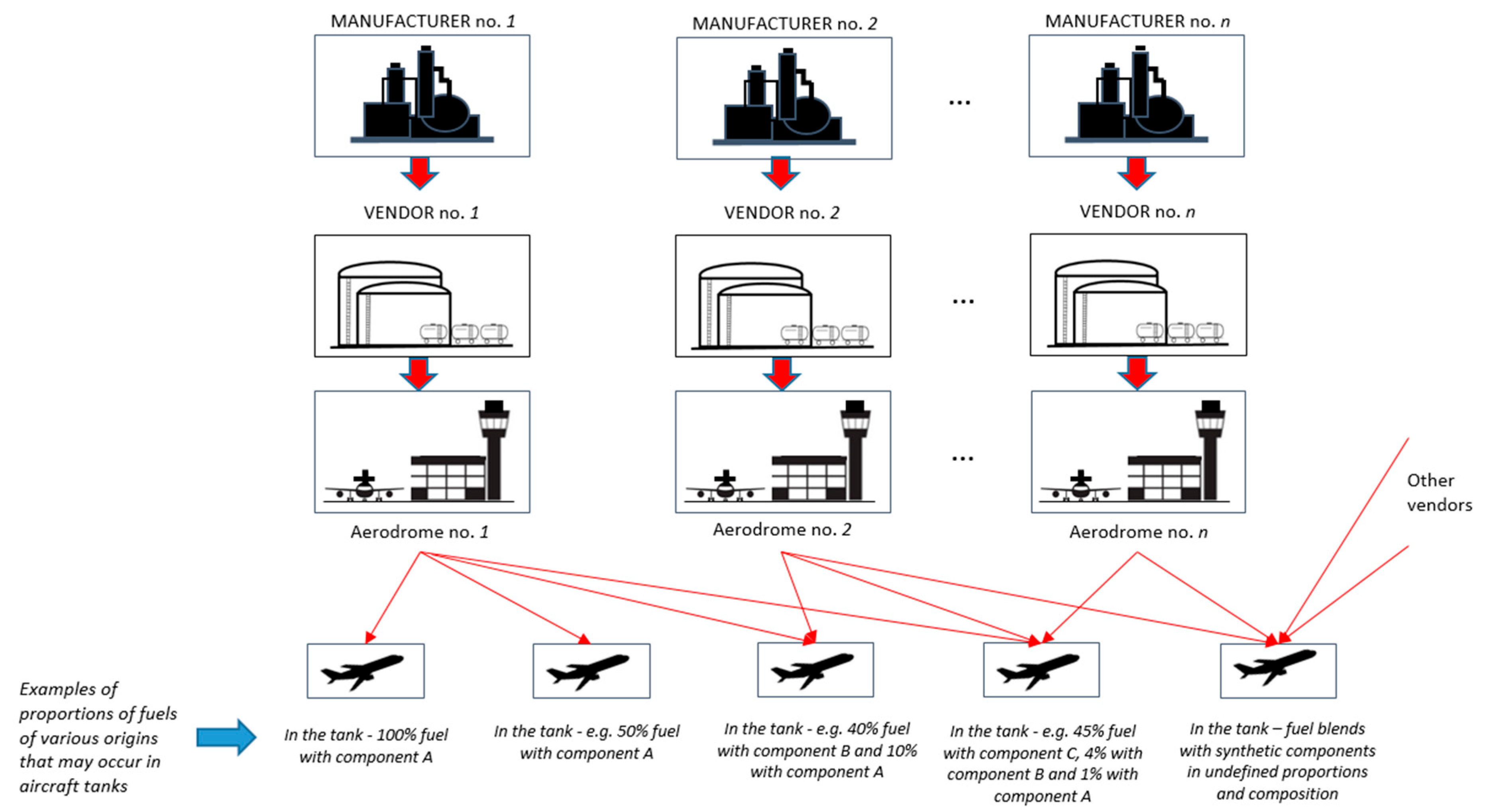
As shown schematically in Figure 2, a given aircraft will be filled at individual aerodromes with fuel containing different synthetic components. Therefore, the fuel tanks of this aircraft will contain a mixture with different synthetic components. Please note that it will also exhibit a relatively low concentration of components introduced at previous aerodromes and a relatively large concentration of the component supplied during the last refueling stage. The situations shown in Figure 2 above were not taken into account in the certification procedure for a fuel with synthetic components. Many years of experience in using petroleum products (engine fuels and lubricating oils) have provided plenty of data indicating the risk of an unexpected change in the properties of mixed products, with a potentially negative impact on the course of processes that the product is involved in during device operation. A number of procedures and tests confirming their inter-miscibility have been developed for these products. At the same time, there are not enough data to indicate that the application of blends of different synthetic fuels in aviation turbine engines does not negatively impact the operation of fuel systems, engines and storage/distribution equipment [7].
The functional simulation of aviation fuel market logistics systems, in a situation of popularized synthetic components, enabled the identification of main risks resulting from the following:
  • Lack of miscibility tests for fuels containing synthetic components;
  • No possibility to determine the chemical composition of fuels pumped through product pipelines and at further distribution stages;
  • Possible noticeable impact of synthetic components at low concentrations on the properties of blends that determine turbine engine operation and the functioning of aviation fuel logistics systems.
The term drop-in fuel used in relation to synthetic components means that a given synthetic component can be mixed with aviation turbine engine petroleum-based fuel. At the same time, this concept does not apply to the miscibility of fuels simultaneously containing various synthetic components. The authors of [8] studied only one blend of 30% HEFA and 8% ATJ, as well as 17% HEFA, 3% ATJ and 5% SIP. The results were related only to Jet A-1 and not to the results obtained for Jet + HEFA and Jet + ATJ. Flow reactor combustion tests show significant differences in quantitative exhaust gas compositions, but it is hard to infer anything based on this, since there are no data on Jet + HEFA and Jet + ATJ. Moreover, there is virtually no information on the operating parameters of the engine that is important for assessing the similarity of the combustion process under different conditions (only particulate matter (PM)).
The authors of [9], in turn, did not provide blend compositions but mixing fuels containing different synthetic components in a storage tank implies that the blend composed in the storage tanks obtained similar concentrations of each synthetic component. At the same time, it should be emphasized that the authors of [9] focused on evaluating emissions, mainly particulate matter, and on economic issues. They did not analyse the impact of composed blends on the operation of engines supplied with this fuel.
Therefore, there is a need to continue research on the methodology of evaluating the miscibility of fuels containing different synthetic components and to conduct a preliminary assessment of the risk of an unexpected disturbance in the course of processes in fuel systems and the fuel combustion process in turbine engines due to unforeseen multi-component properties of Jet A-1 and synthetic component blends.

3. Methodology Concept for Testing the Miscibility of Fuels Containing Various Synthetic Components

The methodology for testing the miscibility of fuels containing various synthetic components takes into account three research stages:
  • Testing selected physical and chemical properties of fuels and their blends at different quantitative proportions;
  • Testing the lubricity of fuels and their blends at different quantitative proportions;
  • Testing the turbine engine combustion process of the fuels and their blends at different quantitative proportions.

3.1. Methods of Physical and Chemical Tests

Physical and chemical properties were selected based on analysing the ASTM D7566 [10] and ASTM D1655 [11] standards, assuming they are of particular importance from the perspective of the combustion process in the engine and turbine engine operation. In relation to an engine equipped with evaporators, the ability to evaporate the fuel, expressed with fractional composition, is an important property.
The following fuel properties were selected:
  • Calorific value (MJ/kg), according to ASTM D3338 [12];
  • Density at 15 °C, (kg/m3), according to ASTM D4052 [13];
  • Viscosity at −20 °C (mm2/s), according to ASTM D445 [14];
  • Fractional composition, according to ASTM D86 [15].

3.2. Methodology of Studying Lubricating Properties Using the Ball-on-Cylinder Lubricity Evaluator (BOCLE) Test Rig

The principle of the method, described in ASTM D5001 [16], is that the following.
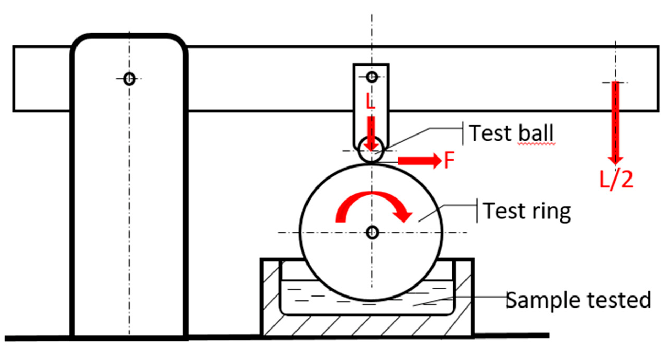
The fluid under test is placed in a test reservoir wherein atmospheric air is maintained at 10% relative humidity. A non-rotating steel ball is held in a vertically mounted chuck and forced against the outside diameter of an axially mounted cylindrical steel ring with an applied load. The test ring is rotated at a fixed speed while being partially immersed in the fluid reservoir. This maintains the ring in a wet condition and continuously transports the test fluid to the ball/ring interface. The wear scar generated on the test ball is a measure of the lubricating property of the fluid [16].
Standard operating conditions are shown in Table 1:
The diagram of the BOCLE frictional connection is shown in Figure 3.

3.3. Methodology of Studying the Engine Fuel Combustion Process Using the MiniJetRig Engine Rig

The combustion process of fuels intended for aviation turbine engines was studied using the MiniJetRig engine stand [17]. The stand consists of the following components:
  • A miniature GTM 120 turbojet engine with a maximum thrust of 120 N, containing a single-stage axial compressor, powered by a single-stage axial turbine and an annular combustion chamber with a set of evaporators;
  • An exhaust gas analyser that enables measuring CO content in exhaust gases;
  • A control system with measurement data recording, based on a measuring card block, which records current, voltage and digital signals.
An exhaust system with a straight collector was selected for the tests. This translates to obtaining a maximum thrust of 70 N.
The tests were conducted for the following rotational speeds: 70,000, 88,000 and 111,000 (rpm). The rotational speed was adjusted by controlling fuel consumptions.
The MiniJETRig is also equipped with portable exhaust analyser, which is used to take samples of exhaust gases from the engine and deliver it through a heated hose to the analysing unit. Electrochemical sensors for measuring O2, CO3 NO2, SO2 and two NDIR sensors for measuring infrared CO2 and CxHy are installed in the analyser block. Individual exhaust gas components were measured over a defined range and a resolution of 1 or 0.1 ppm. Exhaust gas concentrations may be shown on the display of the analyser as volumetric concentration (% or ppm), mass concentration (mg/m3) and mass concentration in relation to oxygen (mg/m3). The exhaust analyser also allows measuring exhaust gas temperature.
The subject matter of the research reviewed in this article is the impact of synthetic components added to a Jet A-1 mineral fuel on the course of the combustion process in the GTM 120 turbine engine. The adopted research methodology (see [2,13,18,19]) may be reduced to comparing the course of the combustion process supplied with Jet A-1 mineral fuel and fuels containing synthetic components. The adopted methodology requires such parameters from the ones measured during the test that would satisfy the role of similarity criteria.
After obtaining the results of exhaust gas chemical composition analysis at hand, as a similarity criterion in evaluating the impact of fuel chemical composition on their combustion process in a GTM 120 engine, CO content in exhaust gases (CO (ppm)) was adopted.
Another adopted similarity criterion in evaluating the impact of fuel chemical composition on the combustion process was the combustion chamber’s temperature gradient (T3) and the temperature upstream of the combustion chamber (T2). It is known that a temperature field of a specific distribution at the combustion chamber outlet impacts the thermal condition of nozzle and rims and rotor turbines and is directly associated with their durability. The authors of [20] postulate introducing methodologies for monitoring temperature field distributions to the procedures of monitored turbine engine operations.
The studies conducted on a MiniJetRig stand enable taking this postulate into account. Six thermocouples were placed in the combustion chamber. The values of T3,1, T3,2, T3,3, T3,4, T3,5 and T3,6 (where T3,1 is temperature T3 in location 1, T3,2 is temperature T3 in location 2, etc.) were recorded in the course of the tests. Based on engine experiments conducted using different turbine engines, it is known that temperature values vary at different locations within the combustion chamber. The presence of a combustion chamber temperature gradient was also observed in the course of numerous tests conducted at AFIT and using the GTM 120 engine.
The GTM 120 engine found at AFIT is employed primarily to study the combustion process of fuels with different chemical compositions. It was observed that if the only variable in the test program is the fuel chemical composition, the combustion chamber temperature gradient magnitude varies for different fuels when maximum and minimum temperatures are always assigned to the same thermocouples (found accordingly in the same sections of the combustion chamber).
It was deemed advisable to add combustion chamber temperature differences to the criteria for evaluating the impact of synthetic components and their blends on the course of the fuel combustion process.
Based on previous experiments, in [21], it was observed that an analysis of functional dependencies between engine operating parameters was much more useful in terms of analysing the chemistry of the combustion process and forecasting the outcomes of using new fuels than the traditional analysis of these parameters and the quantitative comparison of their values. An example is shown later in this article—when analyzing the results (Figure 11).
Functional dependencies can be formulated using the two following methods:
  • Direct comparison of individual parameter values (obtained by conducting experimental tests) and formulating dependencies using a statistical apparatus;
  • Using a theoretical mathematical model of a fuel combustion process as a basis for formulating functional dependencies, which are then experimentally verified.
We believe that path (b) is more useful in terms of generalizing experimental test results. By selecting this track, one should choose a theoretical model that constitutes the basis for formulating the required functional dependencies. A number of mathematical models describing chemical reactions, including fuel combustion, have been developed (see [18,19,22]). However, these models are characterized by lower usability when the test subject matter is the impact of fuel chemical composition on the engine combustion process. The main reason behind this is the difficulty in describing the process, which includes thousands of chemical reactions (Jet A-1 mineral fuels consists of more than a thousand components).
The model that was developed to quantitatively describe energy (thermal, mechanical) effects of chemical reactions that complex reactive blends are subject to is reactivity model αi. The foundations of this model have been developed by the authors of this article [23,24]. Reactivity model αi written as a general equation combines macroscopic external forces f(y) that cause a process, the measurable effect of which is a change in the y parameter with the ϕ(y) function describing the course of the chemical reaction impacting the course of the process. “y” is a measurable parameter that determines the outcomes of the studied process (for example load in lubricity tests or fuel consumption mf in combustion tests); according to the Cauchy and Lagrange theorem used to derive the fundamental model’s dependence, y is the only variable.
Therefore, dependence (1) combines a macroscopically described external force causing the said process with a macroscopically described response of the system relative to external forces. The system’s response is stimulated with chemical reactions caused by external forces. The external force and system response to this force share reactivity coefficient αi: a relative measure of the ability of a given compound/group of compounds to undergo a specific reaction (e.g., decomposition, oxidation, etc.); the reactivity coefficient is assigned to a specific reactive blend participating in a given process. If a series of blends is studied, where each of the blends differs from the others by a certain feature assigned to its selected component, e.g., concentration or chemical structure, comparing reactivity coefficients enables determining the ability of a given reagent to stimulate the course of a specific process, e.g., the creation of the lubrication layer or fuel combustion in an engine. Functions f(y) and ϕ(y) were related to the reference value f0 and ϕ0. These are minimum values f(y) at which the studied reaction appears; it is a state in which the dependence (1) begins to make mathematical and physical sense.
αi = {[f(y) − f0]/[ϕ(y) − ϕ]} ϕ′(y)/f′(y)
The dependence (1) contains a derivative ratio ϕ′(y)/f′(y) = Wwpr, defined as the indicator of process sensitivity relative to chemical reactions, and it is a feature of a given process in a specific system.
Two evaluation criteria were selected in light of the adopted research objective, i.e., preliminary determination of the impact of different synthetic component blends on the combustion process in an aviation turbine engine:
  • Magnitude of combustion-chamber temperature gradient;
  • CO content in exhaust gases.
Based on the results of previous studies [15], both criteria were related to fuel mass flow rate mf, formulating the following dependencies (2) and (3).
(T3max − T2)/(T3min − T2) = f1(mf)
CO = f2(mf)
Reference choices depend on the research objective. The research objective in most publications is to evaluate the impact of engine structure on the emissions of individual exhaust gas components at different aircraft flight stages. For example, CO concentrations were related in [25] to the thrust of GTM 140 and DEGN engines, whereas the authors of [9], dealing with ecological issues of the aviation fuel combustion process, analysed, among others, the impact of fuel consumption on the VOC emission index. Similarly, the creators of [8] assessed the particle mass emission index as a function of fuel flow rate. Therefore, it can be assumed that if the research objective is to evaluate the impact of fuel chemical composition on the turbine engine combustion process, the chemical composition of combustion products (e.g., CO in exhaust gases) and/or the thermal combustion effect (e.g., expressed through a temperature increase in the combustion chamber T3 − T2) should be related to the quantity of a combustion reactant, such as the fuel mass’s flow rate. This enables measurable engine operating parameters to be used for the kinetic and thermodynamic interpretation of the combustion test results for fuels of different chemical composition.
Therefore, it was assumed that the parameters describing the f1 and f2 functions would be used in a comparative assessment of the impact of individual synthetic components, as well as their blends, on the combustion process in the GTM 120 engine.

3.3.1. Description of the Studied Blend Combustion Process Using Functions: (T3max − T2)/(T3min − T2) = f1(mf)

The fundamental dependency (1) for the reactivity model αi can be written as a function of the amount of heat released during the fuel combustion process under actual operating conditions of the GTM 120 test engine (4).
αi = {[(Lsty − L0)/(Esty − ϕ0)]} Wwpr
Based on the aforementioned general characteristics of the reactivity model αi, the following assumptions were adopted to describe the impact of the fuel chemical composition on the combustion process in a miniature turbine engine.
y = mf (g/s)
f(y) = Lsty, where Lst is a quantity with a constant value and dimension (J s/g);
ϕ(y) = Esty where Est is a quantity with a constant value and dimension (J s/g);
Q—heat generated in the combustion chamber due to fuel combustion (J);
f0 = L0 constant value reference function;
ϕ0—constant value reference function.
It was assumed, according to the idea of reactivity model αi where L0 is the minimum external force value inducing a chemical response of the system, that L0 and ϕ0 take the values of L0 > 0, ϕ0 ≈ 0 (simultaneously ϕ0 ≠ 0). Therefore, the dependence (4) can be written as follows:
αi = (Lst mf − L0) Wwpr/Q
where
Q = mf Cw (T3 − T2)
T3—combustion chamber temperature;
T2—temperature upstream of combustion chamber;
Cw—fuel specific heat.
The y value selected as the fundamental variable for describing the combustion process is mf. Therefore, dependences (5) and (6) can be written in the following form (7).
αi = (Lst mf − L0) Wwpr/[Cw (T3 − T2)mf]
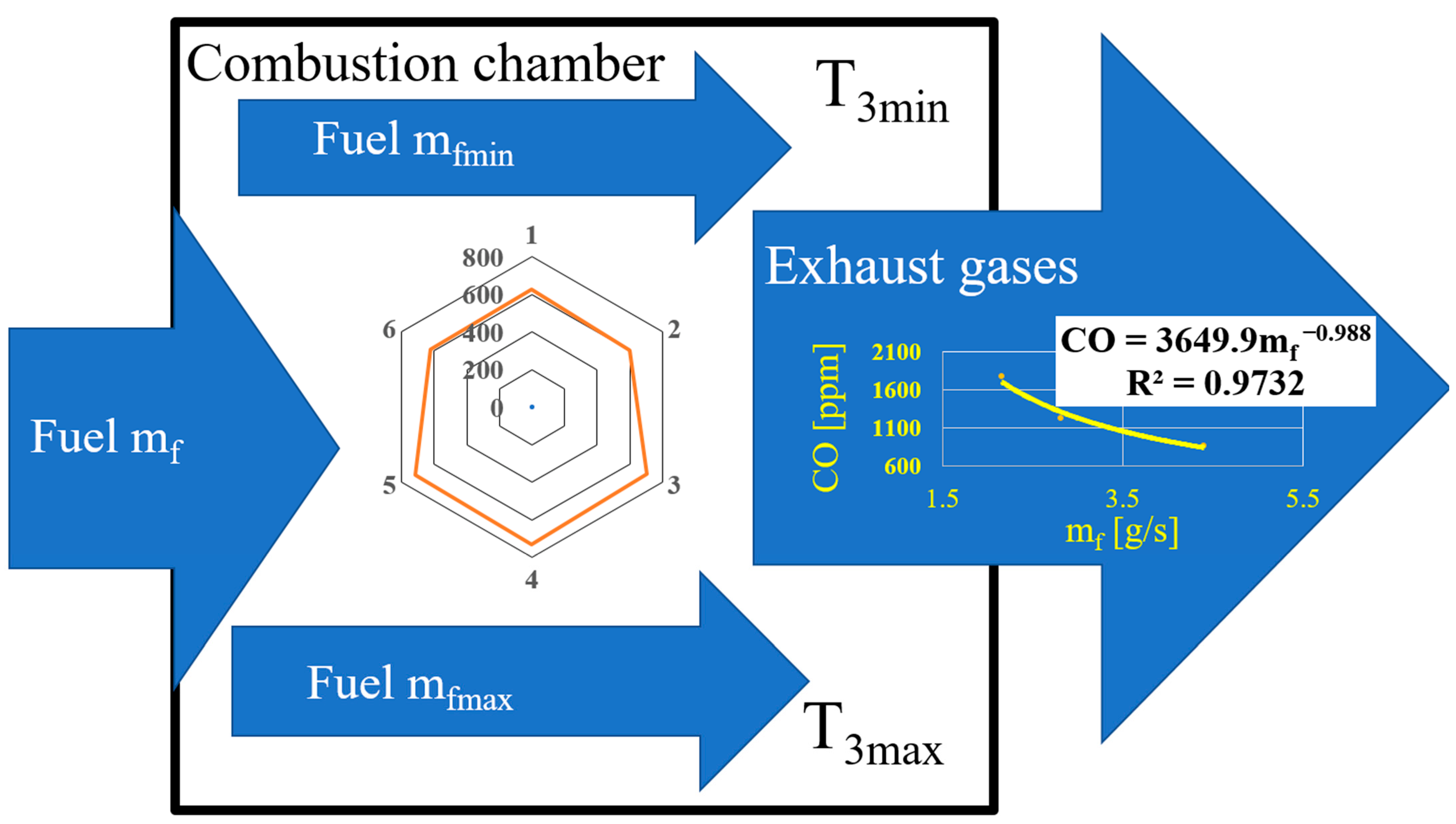
According to the suggestions of [20,26], the main reason for the presence of the combustion chamber temperature gradients is the uneven distribution of the amount of fuel supplied to the combustion process. Therefore, fuel in the combustion chamber flows at different rates in its different sections (Figure 4). In light of the above, dependences (8) and (9) are used to describe the combustion process in the section of the combustion chamber, which experiences maximum fuel mass flow (values in the dependence were marked with the “max” index), as well as to describe the combustion process in the section of the combustion chamber, which experiences the minimum fuel mass flow rate (values in the dependence marked with the “min” index).
αi = (Lst mfmax − L0) Wwpr/[Cw (T3max − T2) mfmax]
αi = (Lst mfmin − L0) Wwpr/[Cw (T3min − T2)mfmin]
It was assumed that if factors causing the combustion chamber temperature gradient change fuel combustion chemistry quantities, but not its quality, then reactivity coefficient αi has the same value in both cases, which enables obtaining the following dependences (10) and (11).
(Lst mfmax − L0)/[(T3max − T2)mfmax] = (Lst mfmin − L0)/[(T3min − T2)mfmin]
(Lst mfmax − L0)/(Lst mfmin − L0) = [(T3max − T2)/[(T3min − T2)] [mfmax/mfmin]
The following were assumed:
  • mfmax = amax mf;
  • mfmin = aminmf;
And then dependence (11) took the following form (12):
[(T3max − T2)/[(T3min − T2)] = mf (Lst amax − L0/mf)/(Lst amin − L0/mf)] (1/mf)[amax/amin]
It was found that the following fragment of the dependence (13) is a constant function.
mf (Lst amax − L0/mf)/(Lst amin − L0/mf)] = 1
Therefore, dependence (12) takes the following form (14):
[(T3max − T2)/[(T3min − T2)] = (1/mf)[amin/amax]
and assuming that the following is the case (15):
amin/amax = g(mf)
the final dependence was obtained.
[(T3max − T2)/[(T3min − T2)] = (1/mf) g(mf)
The adopted hypothesis states that dependence (16) can be written in the form of a power function (17).
(T3max − T2)/(T3min − T2) = a11mfn1

3.3.2. Description of the Studied Blend Combustion Process Using Functions: CO = f2(mf)

The combustion process may be presented as a set of parallel and successive chemical reactions from (18)–(22).
C x H y + x + y 4 O 2 xCO 2 + y 2 H 2 O
C x H y + x 2 + y 4 O 2 xCO + y 2 H 2 O
C x H y + 1 4 yO 2 xC + 1 2 yH 2 O
CO 2 + H 2 CO + H 2 O
CO + 1 2 O 2 CO 2  
The combustion process can be treated as comprising the following:
  • Parallel reactions (18) and (19);
  • Follow-up reactions (19) and (22).
As described in [15], the following kinetic equations can be formulated.
(a)
(23) If parallel reactions (18) and (19):
[CO] = c2kCO t mf−np+1
(b)
(24) If follow-up reactions (19) and (22):
[CO] = {c2kCO [1 + et]/et c5kCO2}mfnp
The CO content in exhaust gases can be written as a power function of fuel mass flow rate mf.

3.4. Adopted Definition of Miscibility and Fuel Miscibility Test Methodology

Recently, we have seen a few publications on the miscibility of fuels for aviation turbine engines containing various synthetic components [9]. However, their authors focused on assessing the impact of blends with different synthetic components on exhaust gas component emissions, notably particular matter. These are undoubtedly important issues; however, given the minor experience in the use of synthetic fuels, it was decided that the research aimed at the failure-free operation of engines supplied with these fuels and, hence, their operational safety, should be a priority. A methodology for testing the miscibility of fuels containing various synthetic components was suggested. It is based on studying selected physical and chemical properties, lubricity and the GTM 120 engine combustion of fuels containing synthetic components and the blends of these fuels in varying quantitative proportions.
The risk of unexpected deviations from regularities observed for fuels containing single synthetic components was adopted as the miscibility evaluation criterion. This risk can be observed when physical and chemical properties, lubricity and criteria for evaluating the combustion process are presented as dependent on the synthetic component content in the fuel. In the case of the combustion process, these dependencies can be formulated based on the adopted fuel combustion process mathematical models. This study used the reactivity model αi.
Therefore, the miscibility of fuels containing different synthetic components was defined as a risk of deviation from the following functional dependencies:
X = ff(c)
where in (25)
X—physico-chemical parameter value;
c—synthetic component content in fuel;
WSD = fw(c)
where in (26)
WSD—BOCLE test consumption;
c—synthetic component content in fuel;
a = fa(c)
n = fn(c)
where in (27) and (28)
a = c2kCO t in Equation (14) or a = {c2kCO [1 + et]/et c5kCO2} in Equation (18);
n = −np + 1 in Equation (14) or np in Equation (18), c—synthetic component content in the fuel;
a11 = faT(c)
n1 = fnT(c)
where in (29) and (30)
a11 and n1 are the parameters of the function (17);
c—synthetic component content in the fuel.

4. Materials—Studied Test Blends

Synthetic components A and B, and Jet A-1 mineral fuel obtained using the hydrotreatment technology were selected for the study. The Jet A-1 fuel used to make up various blends originated from different supplies. The fuel from each supply was characterized by other physical and chemical properties (within the requirements of the ASTM D1655 standard); hence, each batch was identified and marked with an additional symbol:
  • Jet A-1 (A)—Jet A-1 used to compose blends with synthetic component A;
  • Jet A-1 (A1)—Jet A-1 fuel used to compose a blend with 50% (v/v) of synthetic component A;
  • Jet A-1 (B)—Jet A-1 fuel used to compose blends with synthetic component B;
  • Jet A-1 (A)—Jet A-1 used to compose blends with synthetic components B1, B2, B5 and B6.
Synthetic components A and B were added to Jet A-1 fuel. Each of these components was manufactured using a different technology, and each was entered into the list of components approved for use in aviation fuels—ASTM D7566. Components A and B are available on the synthetic fuel market; hence, their names are not given to avoid conflicts of interest. The following blends of these components with the Jet A-1 fuel were composed:
  • 5A—Jet A-1 (A) fuel containing 5% (m/m) of synthetic component A;
  • 20A—Jet A-1 (A) fuel containing 20% (m/m) of synthetic component A;
  • 30A—Jet A-1 (A) fuel containing 30% (m/m) of synthetic component A;
  • 50A—Jet A-1 (A1) fuel containing 50% (m/m) of synthetic component A;
  • 100A—synthetic component A;
  • 50B—Jet A-1 (B) fuel containing 50% (m/m) of synthetic component B;
  • 100B—synthetic component B;
  • B1—Jet A-1 (B/A) fuel containing 50% (v/v) of synthetic component A;
  • B2—Jet A-1 (B/A) fuel containing 25% (v/v) of synthetic component B;
  • B5—Jet A-1 (B/A) fuel containing 20% (v/v) of synthetic component A;
  • B6—Jet A-1 (B/A) fuel containing 10.5% (v/v) of synthetic component B.
Using the aforementioned test fuels, the authors composed the blends described below, reflecting the possible component composition of the fuels in aircraft tanks:
  • B1/B2—synthetic component blend with the following composition: 5% B1 + 95% B2; blend with Jet A-1 contains 2.5% of comp. A and 23.8% of comp. B (total share of synthetic components in the blend with Jet A-1 = 26.3%);
  • B2/B1—synthetic component blend with the following composition: 5% B2 + 95% B1; blend with Jet A-1 contains 47.5% of comp. A and 1.25% of comp. B (total share of synthetic components in the blend with Jet A-1 = 48.75%);
  • 5% B5 + 95% B6; (B5/B6), contains 1% of comp. A and 10.0% of comp. B (total share of synthetic components in the blend with Jet A-1 = 11.0%);
  • 5% B6 + 95%B5; (B6/B5), contains 19.0% of comp. A and 0.5% of comp. B (total share of synthetic components in the blend with Jet A-1 = 19.5%).
This selection of concentrations enabled simulating a situation in which aircraft fuel tanks are filled at aerodrome I with, e.g., fuel B1, followed by fuel B2 at aerodrome II (5% of fuel B1 left in the tanks after landing).
Furthermore, to conduct supplementary tests, the authors prepared blends of Jet A-1(A) and selected synthetic hydrocarbons: C11, C12, C15, C16, C17 and C18. Each of these hydrocarbons was added to Jet A-1(A) in concentrations of: 3, 4, 5, 6 and 7% (v/v), and additionally, hydrocarbons C11 and C16 in concentrations of 10, 25 and 50% (v/v).

5. Test Results

5.1. Physical and Chemical Properties

The test results involving selected physical and chemical properties of blends containing synthetic components A and B are shown in Table 2 and Figure 5 and Figure 6.
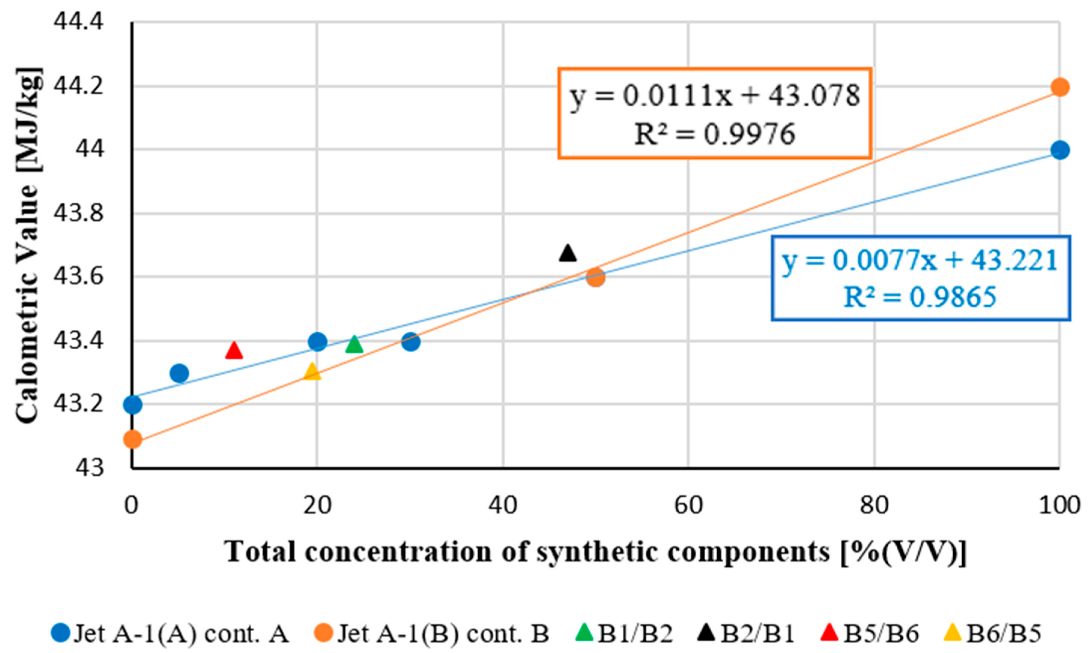
The calorific value is the total effect of enthalpy of all reactions that make up the combustion process. The addition of the synthetic component A or B changes the chemical structure of the fuel; mineral Jet A-1 fuel consists of about 1000 hydrocarbons, whereas synthetic components consist of the few hydrocarbons. The above Figure 5 shows that addition of the component A and component B increases the Calorific Value—in general, higher concentrations of synthetic components result in a higher Calorific Value. Synthetic component A was added to mineral Jet A-1 fuel in various concentrations, including relatively small ones: 5, 20 and 30% (v/v). In this range of concentration, the increase in Calorific Value is not proportional to the increase in the A component’s concentration. The same trend was found for mixtures consisting of two synthetic components A and B (B1/B2, B2/B1, B5/B6 and B6/B5). Moreover, the values of Calorific Value for these mixtures lie on or near the line obtained for mixtures containing only component A (dashed blue line). This analysis indicates the interactions between components A and B, which influence the energy effect of combustion processes.
In summary, it can be said that the data in Table 2 and above charts show that physicochemical properties, including the calorific value of fuels containing mixtures of synthetic components A and B (mixtures B1/B2, B2 B1, B5/B6 and B6/B5), deviate from the trend line of changes in physicochemical properties depending on the concentration of single synthetic components A and B

5.2. Lubricating Properties

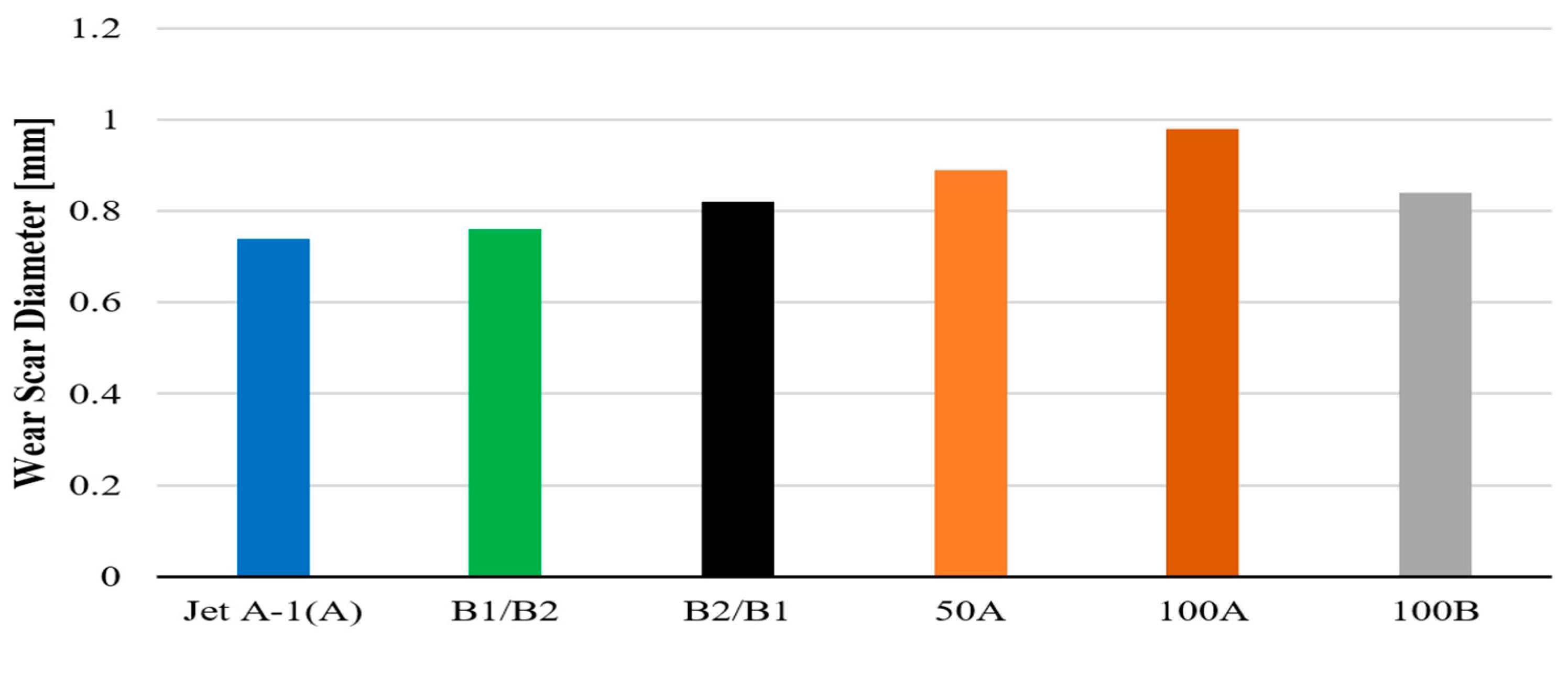
Lubricating properties were tested for blends containing synthetic components A and B, added to Jet A-1 (A) mineral fuel at various concentrations. The results are shown in Figure 7.
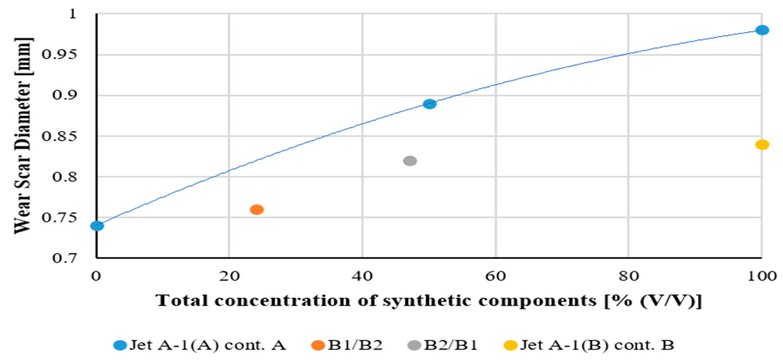
The above charts show that the lubricity of fuels containing mixtures of synthetic components A and B (mixtures B1/B2, B2 B1) deviates from the trend line of changes in physicochemical properties depending on the concentration of single synthetic component A and B. It can be seen that results obtained for B1/B2 and B2/B1 mixtures are situated near the trend line obtained for blends containing the B component (orange line). It can suggest the strong influence of the B component on the Wear Scar Diameter (WSD), but WSD is not proportional to the concentration of B component in the tested mixtures. B1/B2 contains 23.8% (v/v) of component B and B2/B1 1.25% (v/v) of B; thus, the wear should be the result of interactions between all components of tested mixtures.

5.3. MiniJetRig Engine Test Stand Results

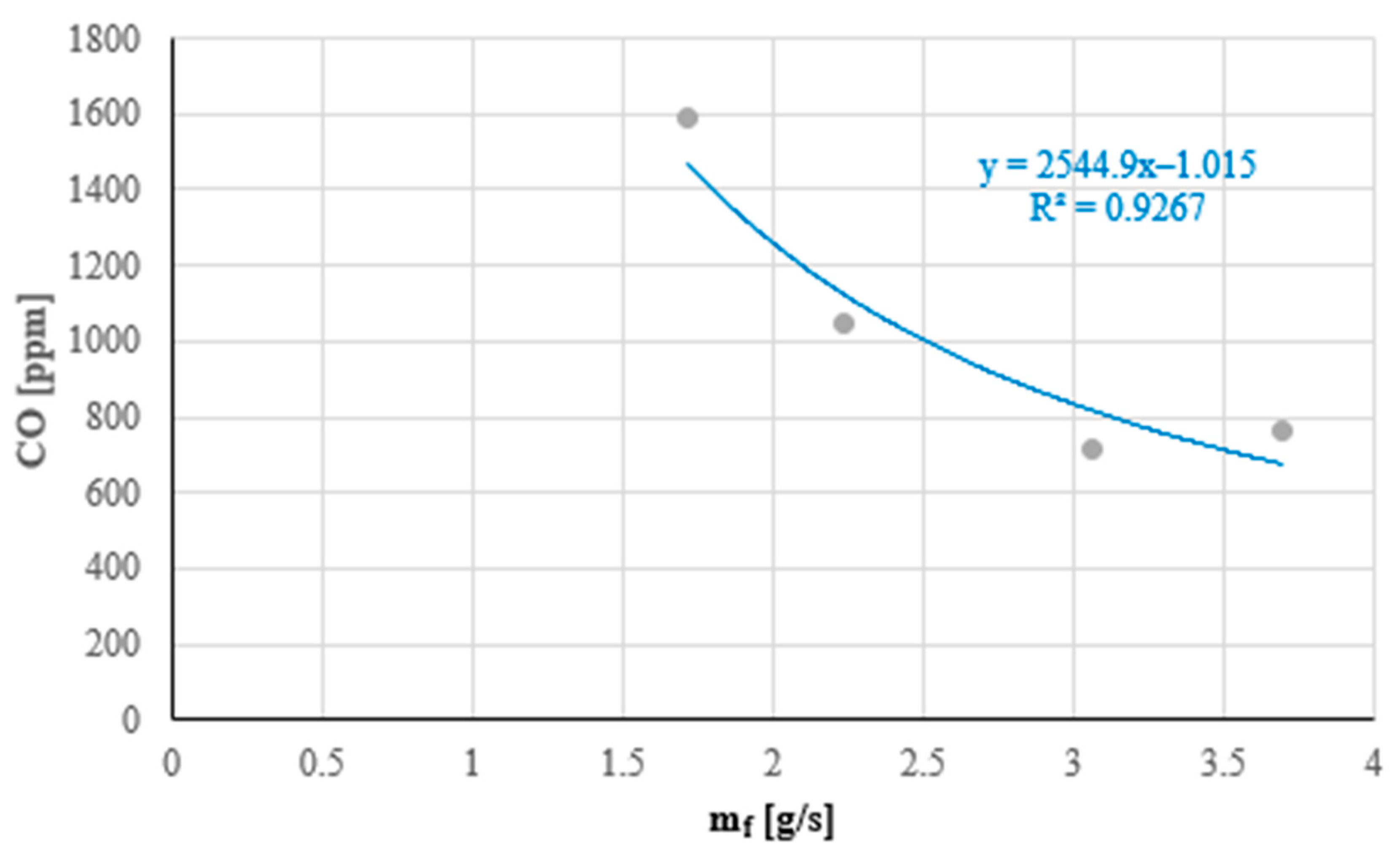
Blends of varying synthetic component A and B content were tested using the MiniJetRig engine test stand and following the methodology above. The measured CO content in exhaust gases was presented as a function of fuel mass flow rate mf. Using the relationship CO = amfn, the parameters of the function were determined for all tested fuels. Examples of measurement results (for fuel Jet A-1 (B)) are provided in Figure 8. For the remaining fuels, the parameters of the function are presented in Table 3.
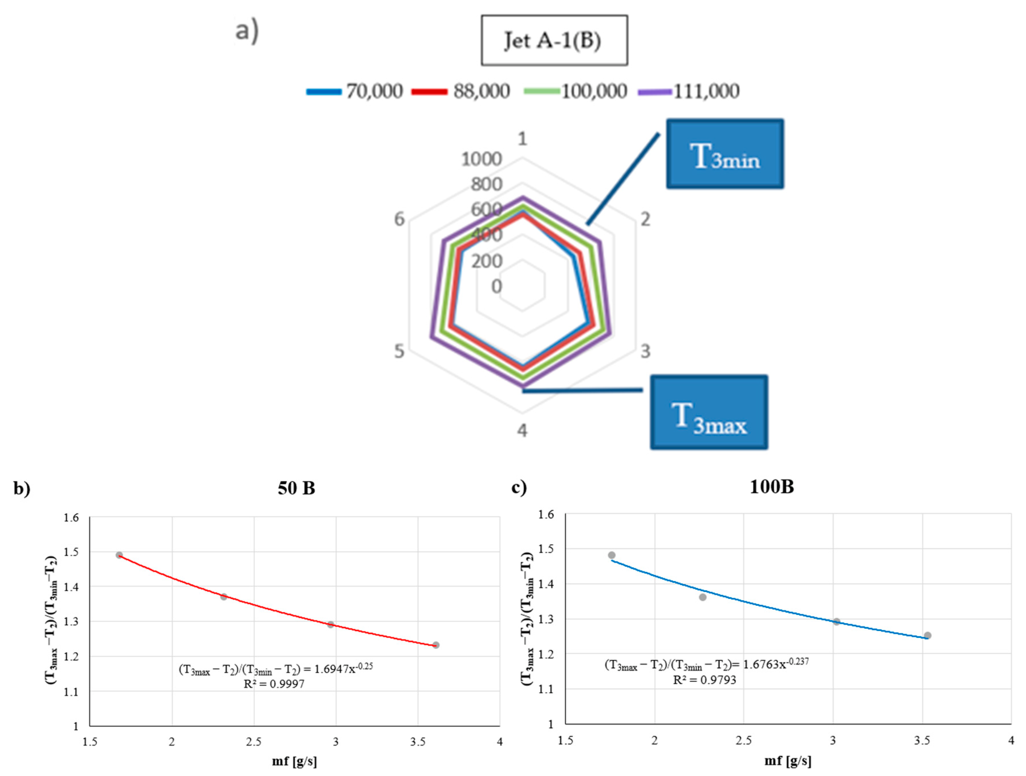
Figure 9 and Table 3 show collective results of combustion chamber temperature measurements during fuel tests. These results constitute the basis for determining the parameters of the (T3max − T2)/(T3min − T2) = a11mfn1 function.
Figure 9 shows that the gradient of temperature in the combustion chamber of the GTM 120 engine depends on fuel mass flow mf and can be explained as power function of the fuel mass flow mf. It was found that in the range of rotational speeds between 70,000 and 120,000 rpm, (T3max − T2)/(T3min − T2) decreases with an increase in mf and consequently with the increase in the rotational speed of GTM 120 engine. Figure 9a shows the temperature in various points of the combustion chamber (see Figure 4) obtained for mineral Jet A-1 fuel. Figure 9b shows the power functions obtained for 50B and 100B mixtures. Figure 9b indicates that the parameters of power functions depend on the concentration of synthetic components, which in this case is B. Similar dependences were obtained for all tested fuels—mixtures containing synthetic components A and B. The parameters of power functions, experimentally found for all tested mixtures, were related to such parameters obtained for mineral Jet A-1 fuels. This made it possible to compare the course of power functions obtained for mixtures containing synthetic components with the power function obtained for mineral Jet A-1 fuel. Ratios a11/a11jet and n1/n1jet were determined (see Table 4) as the combustion process’ similarity criteria.

6. Discussion of the Results

6.1. Impact of Synthetic Component Content on Selected Physical and Chemical Properties of the Fuels

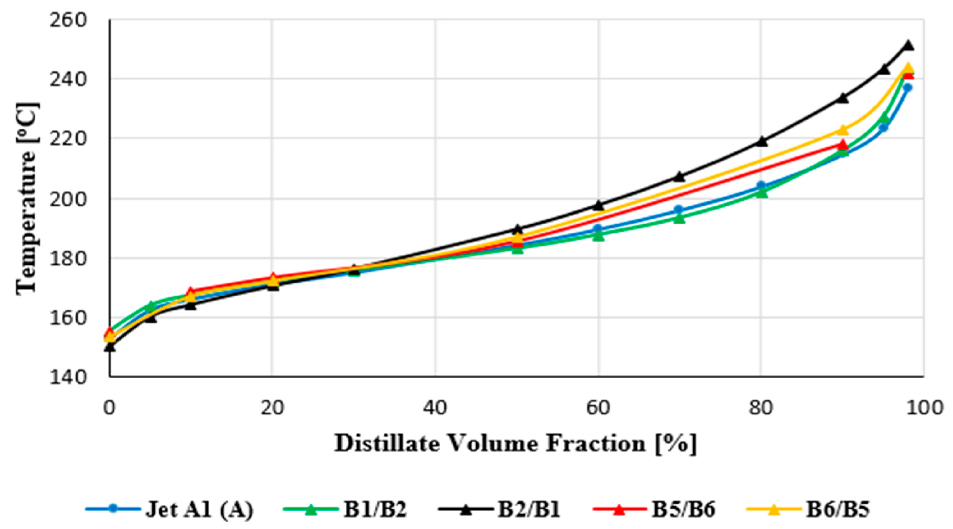
The dependences of calorific value Wo on the content of synthetic components A and B shown in Figure 5 do not indicate noticeable deviations in measurements (according to Table 2a–c—column “repeatability of the method in laboratory” results for the B1/B2 and B2/B1 blends from the change line of that parameter value, compared to single components A and B). Similarly, the observation of distillation curve waveforms (Figure 6) does not indicate significant deviations in the case of any of the tested blends.
Therefore, based on testing selected physical and chemical properties, no risks of the lack of miscibility of fuels containing synthetic components A and B were observed.

6.2. Impact of Synthetic Component Content on Fuel Lubricity

Moreover, the BOCLE method lubricity tests of the B1/B2 and B2/B1 blends do not indicate the presence of unexpected, significant deviations from the waveform of the WSD = fw(c) dependence, compared to the Jet A-1 fuel. Nonetheless, the WSD values for the B2/B1 blend containing 47.5% of comp. A and 1.25% of comp. B are lower than it would appear from the trend line for blends of the Jet A-1 fuel and synthetic component A. This deviation does not indicate a risk of the fuel losing the required lubricating properties; however, it confirms the validity of the researching the miscibility of fuels containing various synthetic components, described herein.

6.3. Impact of Synthetic Component Content on the GTM 120 Engine Fuel Combustion Process

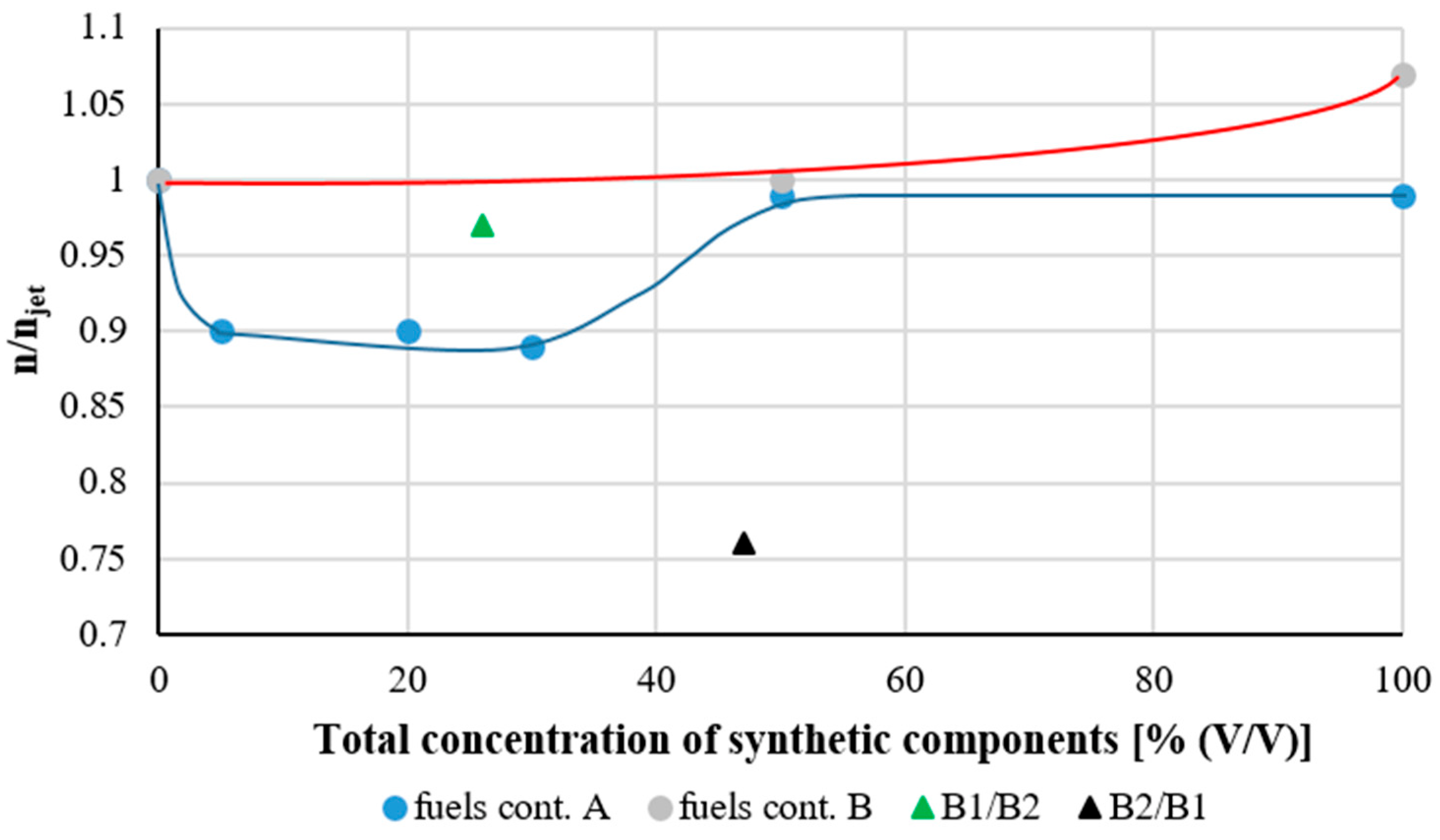
The conducted tests of the combustion process for fuels containing synthetic components A and B and their blends (B1/B2 and B2/B1) using the MiniJetRig engine stand (GTM 120 engine) enabled a conclusion that, according to the evaluation criterion parameter a of the CO = a mfn function, the result significantly deviates from the trend lines (red and blue) observed for blends containing both component A and B (see Figure 10).
On the other hand, a similar situation was observed for the B2/B1 blend, evaluated as per the criterion: n parameter of the CO = a mfn function.
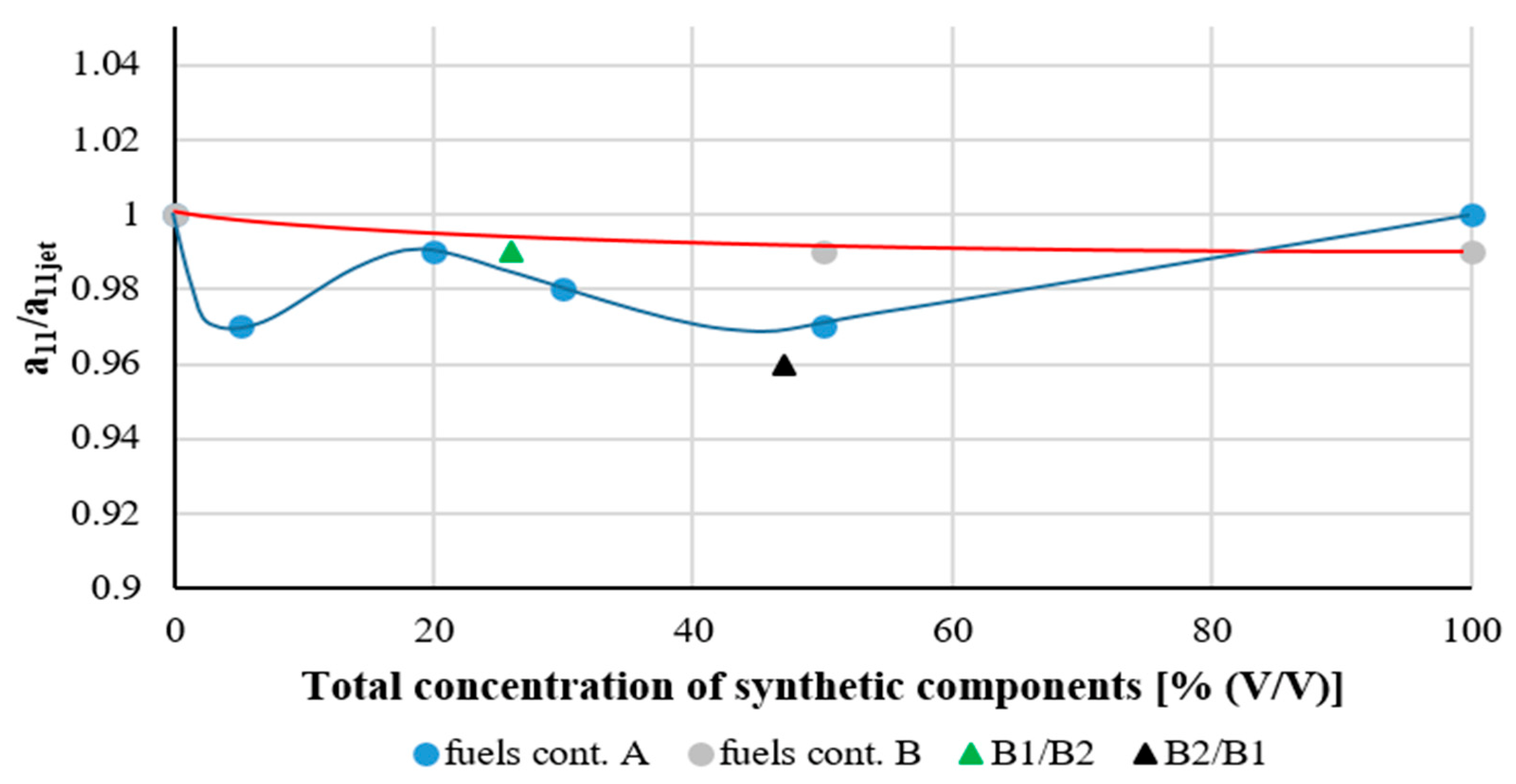
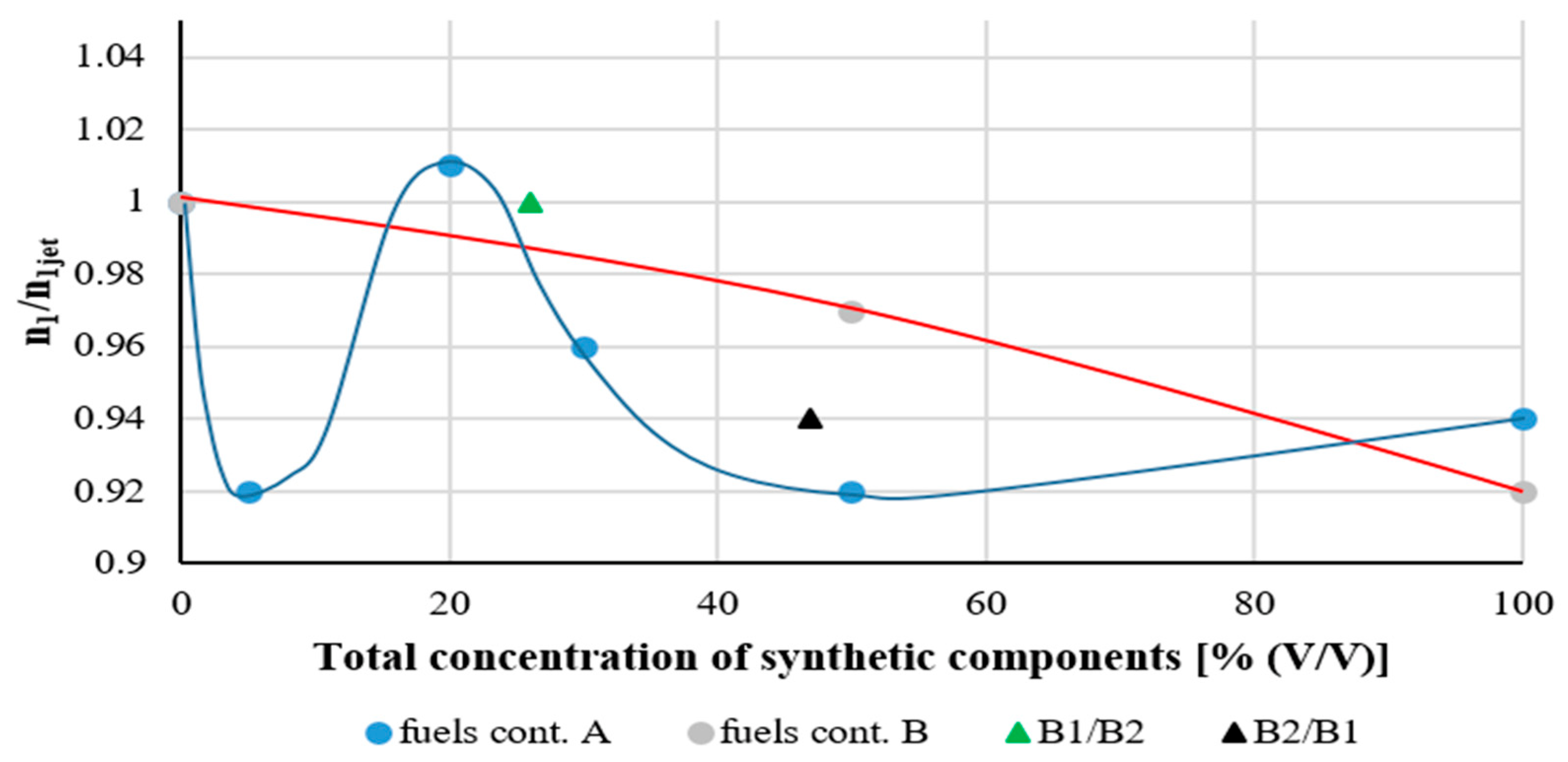
In the case of miscibility evaluation criteria a11 and n1—parameters of the (T3max − T2)/(T3min − T2) = a11mfn1 function—significant deviations from the trend lines (red and blue) obtained for blends of component A and component B were observed. These deviations were the case in relation to both parameter a11 and n1 (see Figure 11).
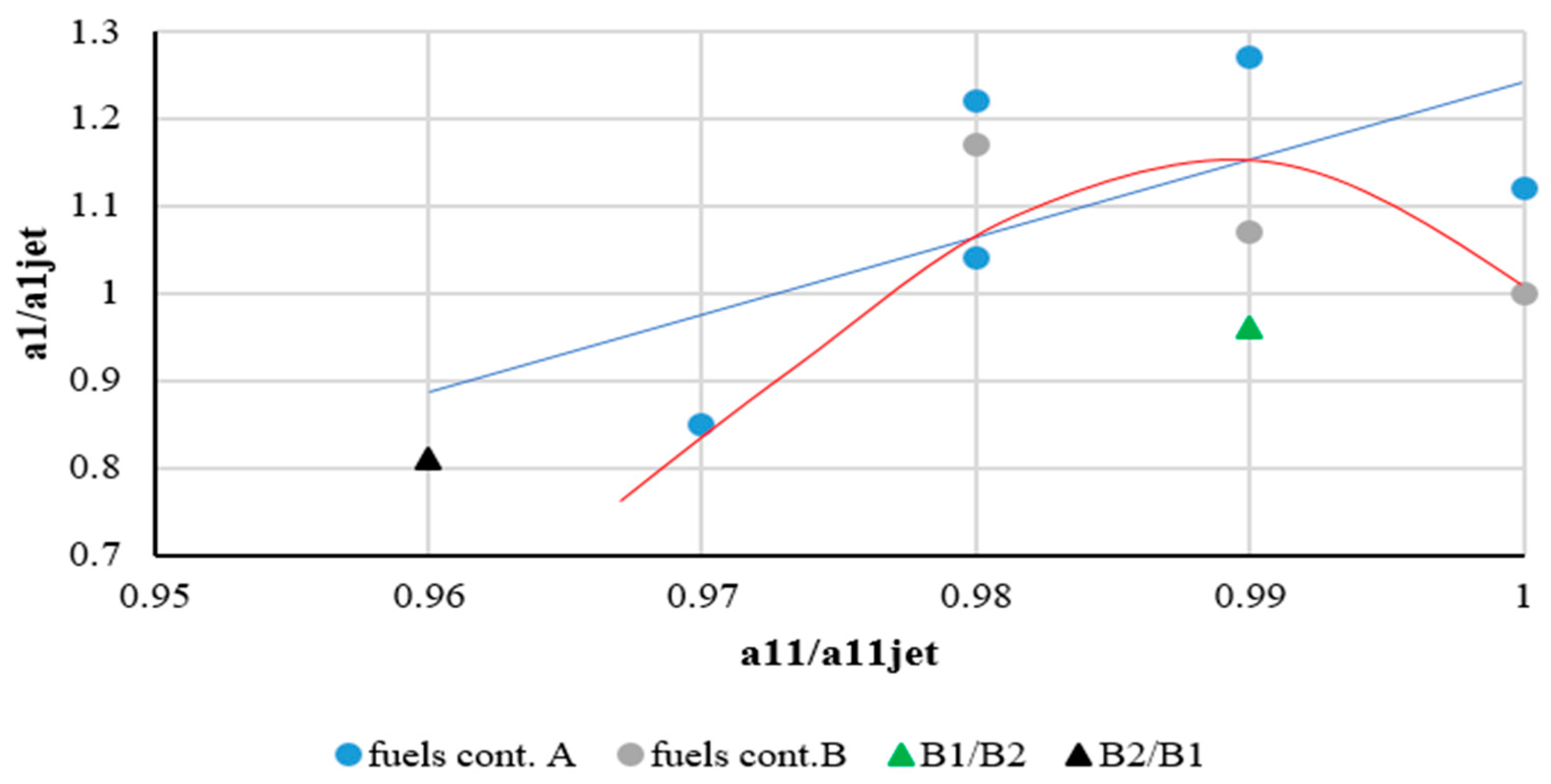
Figure 12 and Figure 13 show a comparison of both criteria, i.e., based on measuring CO content in exhaust gases (a1/a1jet and n/njet) and the one based on measuring (T3max − T2)/(T3min − T2). The following were observed:
  • There is a clear relationship between the values of both criteria.
  • It is different for synthetic component A and synthetic component B.
  • B1/B2 and B2/B1 blends clearly deviate from both these relationships (see red and blue lines on the Figure 12 and Figure 13).
The conducted functional analysis of the aircraft fuel supply logistics systems leads to the following conclusions:
  • The availability of a greater number of synthetic components, approved after satisfying criteria set out by ASTM, leads to them being mixed in the fuel tanks of aircraft.
  • The blends formed in aircraft tanks will contain a relatively high concentration of one of the components and a relatively low concentration of the other component.
  • There is a real possibility that many different components appear simultaneously within a blend, which may significantly complicate the scenarios described in this article.
The experience gained in the course of conducting various tests involving fuels and other operating liquids indicates that blends of different synthetic components and the Jet A-1 mineral fuel may exhibit deviations from expected property values and impact the course of processes such as fuel pump lubrication or fuel combustion in a turbine engine in an unforeseen manner.
It was assumed that the risk of unexpected deviations from regularities observed for fuels containing single synthetic components should be the miscibility evaluation criterion. This risk can be observed when physical and chemical properties, lubricity and criteria for evaluating the combustion process are presented as dependent on the synthetic component content in the fuel. In the case of the combustion process, these dependencies can be formulated based on the adopted fuel combustion process mathematical models. This study applied reactivity model αi, which may be used for the physical interpretation of the parameters of the analysed functions and attempts to explain appearing deviations in further research.
In order to verify the thesis that the parameters of functional dependences describing the GTM 120 engine fuel combustion process can be a criterion for evaluating the miscibility of fuels containing different synthetic components, the authors studied blends of Jet A-1 fuel and synthetic components A and B. Both components were tested following the ASTM procedure and approved (entered in the ASTM D1655 standard [11]).
The conducted tests of physical and chemical properties—selected parameters shown in Figure 5 and Figure 6—do not point to the presence of unexpected deviations from regularities that may result from a change in the synthetic component concentration in the fuel.
Lubricity tests of B1/B2 and B2/B1 fuels do not indicate unexpected significant effects; however, the WSD result obtained for the B2/B1 blend and blends of in the Jet A-1 fuel indicates a completely different behaviour within the tribological process for low concentrations of these hydrocarbons—below 10% (v/v), compared to higher concentrations—up to 50% (v/v). These observations incline to pay more attention to certain properties of fuels containing relatively low quantities of synthetic components.
The GTM 120 engine combustion process involving blends of the Jet A-1 fuel and synthetic components A and B was tested in accordance with the methodology described above. The following were measured in the course of the tests:
  • T2 temperature upstream of the combustion chamber (°C);
  • T3 combustion chamber temperature (six measurements) (°C);
  • CO content in exhaust gases (ppm).
The above-mentioned measured values were related to mf fuel mass flow rate (g/s).
Using a pre-developed reactivity model αi, the authors formulated the following dependences (31) and (32), linking criteria parameters with fuel mass flow rate.
(T3max − T2)/(T3min − T2) = f1(mf)
CO = f2(mf)
Experimental data enabled determining power functions (33) and (34).
(T3max − T2)/(T3min − T2) = a11(mf)n1
CO = a(mf)n
The values of the a11, n1, a and n parameters were used to evaluate the fuel blend’s composition impact on the combustion process. Please note that if the study used the methodology of analysing obtained results that are previously described in the literature (i.e., the results of individual measurements were presented, e.g., CO, for different rotational speeds), it would be hard to apply them to assess the miscibility of individual synthetic components. The suggested methodology (i.e., formulating functional dependences for different engine operating conditions, followed by a comparison of the parameters of obtained functions for fuels with varying contents of synthetic components and their blends, relative to similar parameters for a batch of the Jet A-1 mineral fuel used to compose blends with components A and B) offers significantly greater analytical possibilities.

7. Conclusions

Such an evaluation of fuels with different content of components A and B and their blends enabled concluding the following:
  • The development of fuels containing synthetic components will cause them to mix in aircraft tanks. Therefore, there is a need to develop research on the methodology of evaluating the miscibility of fuels containing different synthetic components.
  • The methodology of testing the miscibility of fuels containing various synthetic components proposed in this article includes the following: standard laboratory tests (mainly normal distillation and calorific value measurement), BOCLE lubricity test and engine tests providing experimental data for relationships (33) and (34).
  • The proposed methodology was initially verified in laboratory, lubricity and engine tests using blends of mineral Jet A-1 fuel and synthetic components A and B, both tested following the ASTM procedure and approved (entered in the ASTM D1655 standard [11]). As a result of the research, the following was observed.
    In the case of high concentrations of synthetic components added individually, the values of the a11/a11jet, n1/n1jet, a/ajet and n/njet parameters undergo a change proportional to the concentration of the synthetic component in the fuel.
    However, in the case of lower concentrations (up to 30% (v/v)), the changes in the a11/a11jet, n1/n1jet, a/ajet and n/njet parameters are different than for high concentrations.
    The impact of each of the tested components on the course of the aforementioned relationships differs.
    The values of the a11/a11jet, n1/n1jet, a/ajet and n/njet parameters obtained for the B1/B2 and B2/B1 blends deviate from the trend line for changes acquired for blends containing individual synthetic components A and B. This indicates that the presence of even a very small quantity of one of the components impacts the course of the combustion process in an aviation turbine engine.
The aforementioned conclusions do not permit us to make decisions regarding the possible application of synthetic components—there are no grounds to assess how much the test results obtained for B1/B2 and B2/B1 blends impact the operation of turbine engine under normal aircraft operating conditions. This issue should be taken into account in synthetic fuel test procedures. Furthermore, please bear in mind that the demonstrated changes do not pose a significant threat when appearing as individual cases. However, when the application of synthetic components becomes more common or even inevitable, this may lead to adverse phenomena and even reduced engine operational safety in extreme cases.

Author Contributions

Conceptualization, W.D., U.K. and A.K.; methodology, W.D and U.K.; validation, U.K.; formal analysis, A.K.; investigation, W.D., U.K. and A.K.; resources, W.D. and U.K.; data curation, U.K.; writing—original draft preparation, W.D. and A.K.; writing—review and editing, A.K.; visualization, W.D. and U.K.; supervision, A.K. All authors have read and agreed to the published version of the manuscript.

Funding

This research received no external funding.

Institutional Review Board Statement

Not applicable.

Informed Consent Statement

Not applicable.

Data Availability Statement

Not applicable.

Conflicts of Interest

The authors declare no conflict of interest.

References

  1. Directive (EU). 2018/2001 of the European parliament and of the council of 11 December 2018 on the promotion of the use of energy from renewable sources. Off. J. Eur. Union 2018, 5, 82–209. [Google Scholar]
  2. Gawron, G.; Białecki, T. Impact of a jet A-1/HEFA blend on the performance and emission characteristics of a miniature turbojet engine. Int. J. Environ. Sci. Technol. 2018, 15, 1501–1508. [Google Scholar] [CrossRef]
  3. Yang, J.; Xin, Z.; Corscadden, K.; Niu, H. An overview on performance characteristics of bio-jet fuels. Fuel 2019, 237, 916–936. [Google Scholar] [CrossRef]
  4. Kumal, R.R.; Liu, J.; Gharpure, A.; Wal, R.L.V.; Kinsey, J.S.; Giannelli, B.; Stevens, J.; Leggett, C.; Howard, R.; Forde, M.; et al. Impact of biofuel blends on black carbon emissions from a gas turbine engine. Energy Fuels 2020, 34, 4958–4966. [Google Scholar] [CrossRef] [PubMed]
  5. ASTM D4054; Standard Practice for Evaluation of New Aviation Turbine Fuels and Fuel. ASTM International: West Conshohocken, PA, USA, 2022.
  6. Dzięgielewski, W.; Gawron, B.; Kulczycki, A. Low temperature properties of fuel mixtures of kerosene and fame type used to supply turbine engines in marine and other non-aeronautical applications. Pol. Marit. Res. 2015, 22, 101–105. [Google Scholar] [CrossRef]
  7. AFIT Technical Documentation—Internal documentation, not to be published in full.
  8. Schripp, T.; Grein, T.; Zinsmeister, J.; Oßwald, P.; Koehler, M.; Mueller-Langer, F.; Posselt, D.; Hauschild, S.; Marquardt, C.; Scheuermann, S.; et al. Technical application of a ternary alternative jet fuel blend—Chemical characterization and impact on jet engine particle emission. Fuel 2021, 288, 119606. [Google Scholar] [CrossRef]
  9. Müller-Langer, F.; Dögnitz, N.; Marquardt, C.; Zschocke, A.; Schripp, T.; Oehmichen, K.; Majer, S.; Bullerdiek, N.; Halling, A.; Posselt, D.; et al. Multiblend JET A-1 in practice: Results of an R&D project on synthetic paraffinic kerosenes. Chem. Eng. Technol. 2020, 43, 1514–1521. [Google Scholar] [CrossRef]
  10. ASTM D7566; Standard Specification for Aviation Turbine Fuel Containing Synthesized Hydrocarbons. 2022. Available online: https://www.astm.org/d7566-22.html (accessed on 21 August 2022).
  11. ASTM D1655; Standard Specification for Aviation Turbine Fuels. 2022. Available online: https://www.astm.org/d1655-22.html (accessed on 21 August 2022).
  12. ASTM D3338; Standard Test Method for Estimation of Net Heat of Combustion of Aviation Fuels. 2020. Available online: https://www.astm.org/d3338-20.html (accessed on 21 August 2022).
  13. ASTM D4052; Standard Test Method for Density and Relative Density of Liquids by Digital Density Meter. 2022. Available online: https://www.astm.org/d4052-22.html (accessed on 21 August 2022).
  14. ASTM D445; Standard Test Method for Kinematic Viscosity of Transparent and Opaque Liquids (the Calculation of Dynamic Viscosity). 2021. Available online: https://www.astm.org/d445-21.html (accessed on 21 August 2022).
  15. ASTM D86; Standard Test Method for Distillation of Petroleum Products at Atmospheric Pressure. 2020. Available online: https://www.astm.org/d86-20.html (accessed on 21 August 2022).
  16. ASTM D5001; Standard Test Method for Measurement of Lubricity of Aviation Turbine Fuels by the Ball-on-Cylinder Lubricity Evaluator (BOCLE). 2019. Available online: https://www.astm.org/d5001-19.html (accessed on 21 August 2022).
  17. Gawron, B.; Białecki, T. The laboratory test rig with miniature jet engine to research aviation fuels combustion process. J. KONBiN 2017, 4, 79–89. [Google Scholar] [CrossRef]
  18. Tanaka, S.; Ayala, F.; Keck, J.C.; Heywood, J.B. Two-stage ignition in HCCI combustion and HCCI control by fuels and additives. Combust. Flame 2003, 132, 219–239. [Google Scholar] [CrossRef]
  19. ARP 1533C; Procedure for the Analysis and Evaluation of Gaseous Emission from Aircraft Engines. SAE International: Warrendale, PA, USA, 2016.
  20. Pawlak, W.I.; Balicki, W. Influence of an inequality of gas thermal field at the jet engine turbine inlet on to the speed of transient processes—The results of experiments with real engine. J. Kones Intern. Combust. Engines 2003, 10, 3–4. [Google Scholar]
  21. Białecki, T.; Dzięgielewski, W.; Kowalski, M.; Kulczycki, A. Reactivity model as a tool to compare the combustion process in aviation turbine engines powered by synthetic fuels. Energies 2021, 14, 6302. [Google Scholar] [CrossRef]
  22. Govindan, R.; Jakhar, O.; Mathur, Y. Computational analysis of Thumba biodiesel-diesel blends combustion in CI engine using Ansys-fluent. IJCMS 2014, 3, 29–39. [Google Scholar]
  23. Kulczycki, A. Theoretical approach to modelling the combustion process in turbine engines fuelled by alternative aviation fuels containing various components/bio components. Combust. Engines 2017, 71, 245–249. [Google Scholar] [CrossRef]
  24. Białecki, T.; Dzięgielewski, W.; Gawron, B.; Kaźmierczak, U.; Kulczycki, A. The role of molecularly ordered structures in energy transport enhancement during combustion process—A new conception of a reaction mechanism of fuel components oxidation. J. KONES Powertrain Transp. 2018, 25, 17–24. [Google Scholar]
  25. Przysowa, R.; Gawron, B.; Białecki, T.; Łęgowik, A.; Merkisz, J.; Jasiński, R. Performance and emissions of a micro-turbine and turbofan powered by alternative fuels. Aerospace 2021, 8, 25. [Google Scholar] [CrossRef]
  26. Józef, B.; Artur, K.; Jerzy, P. The impact of unevenness and instability of flue gas temperature on the technical condition of gas turbine blades. J. KONES Power Train Transp. 2018, 25, 45–51. [Google Scholar]
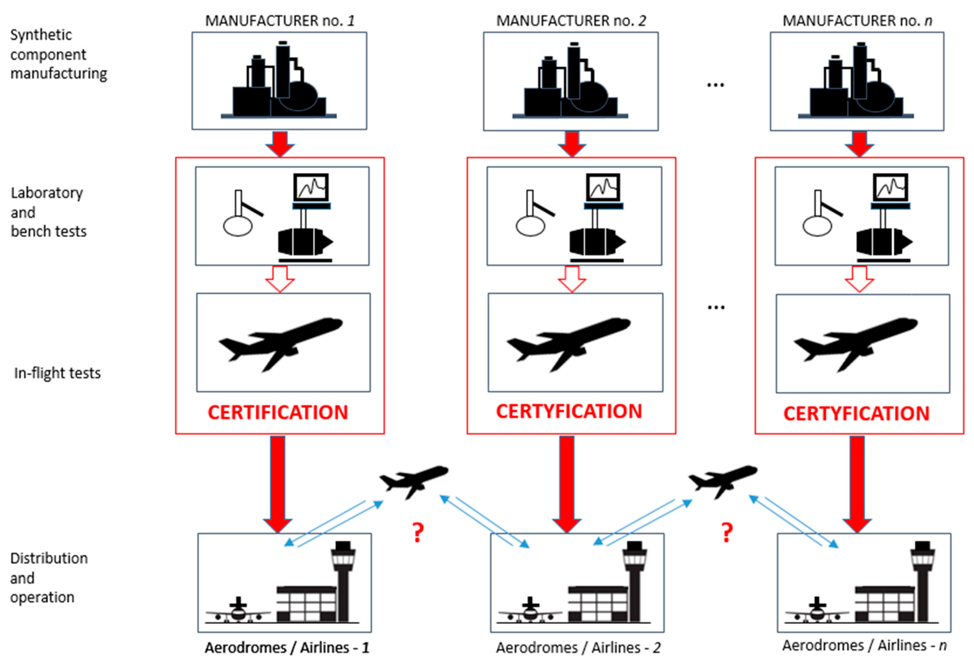
Figure 1. Diagram of certification tests for fuels containing synthetic components.
Energies 15 06187 g001
Figure 2. Technical and logistics issue: supply of aircraft with various fuels at different aerodromes.
Energies 15 06187 g002
Figure 3. Schematic diagram of BOCLE, where L is the loading force, and F is the friction force.
Energies 15 06187 g003
Figure 4. Adopted criteria for evaluating the properties of synthetic components in the Jet A-1 mineral fuel on the combustion process in a miniature turbine engine: (i) distribution of combustion process temperature (T3) and (ii) CO content in exhaust gases (CO).
Energies 15 06187 g004
Figure 5. Dependence of calorific value on the total content of synthetic components A and B.
Energies 15 06187 g005
Figure 6. Fractional composition of blends composed using Jet A-1(A).
Energies 15 06187 g006
Figure 7. BOCLE method lubricity of the tested blends.
Energies 15 06187 g007aEnergies 15 06187 g007b
Figure 8. Examples of CO measurements as the mf function—Jet A-1(B) fuel.
Energies 15 06187 g008
Figure 9. Dependence examples: (a) T3 temperature distribution in the combustion chamber; (b) and (c) are examples of the (T3max − T2)/(T3min − T2) dependence on mf.
Energies 15 06187 g009
Figure 10. Dependences a/aJet and n/nJet on the total concentration of synthetic components A and B.
Energies 15 06187 g010aEnergies 15 06187 g010b
Figure 11. Dependences a11/a11Jet and n1/n1Jet on the total concentration of synthetic components A and B.
Energies 15 06187 g011aEnergies 15 06187 g011b
Figure 12. Relationship between a1/a1jet and a11/a11jet values (relationship between the criteria of similarity for the combustion process sequence, based on measuring CO content in exhaust gases and combustion chamber temperature gradient (T3max − T2)/(T3min − T2)).
Energies 15 06187 g012
Figure 13. Relationship between n/n1jet and n1/n11jet values (relationship between the criteria of similarity for the combustion process sequence, based on measuring CO content in exhaust gases and combustion chamber temperature gradient (T3max − T2)/(T3min − T2)).
Energies 15 06187 g013
Table 1. Standard test conditions on the BOCLE apparatus.
ParameterRequirement
Fluid Volume50 ± 1.0 mL
Fluid Temperature25 ± 1 °C
Conditioner Air10 ± 0.2% relative humidity at 25 ± 1 °C
Fluid pre-treatment0.50 L/min flowing through and 3.3 L/min over the fluid form 15 min
Fluid test conditions3.8 L/min flowing over the fluid
Applied Load1000 g (500 g weight) (±1 g)
Cylinder Rotational Speed240 ± 1 rpm
Test Duration30 ± 0.1 min
Test Ring of SAE 8720 steel, possessing a Rockwell hardness “C” scale (HRC) number of 58 to 62 and a surface finish of 0.56 to 0.71 µm root mean square
Test Ball chrome alloy steel, made from AISI standard steel No. E-52100, with a diameter of 12.7 mm, Grade 5 to 10; the HRC shall be 64 to 66; the ball is described in ISO 3290-1
Table 2. Properties of tested fuels. (a) Synthetic component A; (b) synthetic component B; (c) blends containing synthetic components A and B.
(a)
Fuel PropertiesJet A1 (A)5% A20% A30% A50% A100%ARepeatability of the Method in Laboratory
Density at 15 °C, kg/m3793.1790.5787.0782.7770.7-0.11
Viscosity at −20 °C, mm2/s3.0693.2883.4033.4703.481-0.008
Calorific value, MJ/kg43.31243.33543.48443.57043.74044.2000.021
Aromatics, % (v/v)15.114.312.110.67.6-1.0
Distillation: --
10% Recovery, °C166.1170.6169.9169.02.3
50% Recovery, °C183.4186.8188.3189.31.8
90% Recovery, °C208.1214.1220.2224.72.6
end point, °C231.2239.4246.7249.53.9
(b)
Fuel PropertiesJet A-1 B50% B100% BRepeatability of the Method in Laboratory
Density at 15 °C, kg/m3793.0776.1758.60.11
Viscosity at −20 °C, mm2/s3.0623.6544.7400.008
Calorific value, MJ/kg43.23143.59944.0270.021
Aromatics, % (v/v)17.38.80.01.0
Distillation:
10% Recovery, °C166.1175.5170.52.3
50% Recovery, °C183.4181.2182.11.8
90% Recovery, °C208.1210.3209.02.6
end point, °C231.2262.7246.23.9
(c)
Fuel PropertiesJet A-1 (B/A)B1/B2B2/B1B5/B6B6/B5Repeatability of the Method in Laboratory
Density at 15 °C, kg/m3800.5789.5777.0--0.11
Viscosity at −20 °C, mm2/s3.1763.4283.564--0.008
Calorific value, MJ/kg43.09443.38843.67643.37143.3070.021
Distillation:
10% Recovery, °C166.1167.3164.3168.8167.22.3
50% Recovery, °C184.3183.0189.6185.5187.01.8
90% Recovery, °C214.7215.8233.8218.2223.02.6
end point, °C236.9243.4251.7241.7244.13.9
Table 3. Empirically determined values of the a and n parameters of the CO = a mfn dependence; the “jet” index refers to a and n value obtained for the Jet A-1 fuel appropriate for a given sample batch, marked in the table with colours.
FuelrpmCOmfa/ajetn/njet
Jet A-1 (B)70,00015881.7211
88,00010472.24
104,0007143.06
111,0007653.7
50B70,00016601.681.071.03
88,00010762.32
104,0007702.97
111,0007823.61
100B70,00017151.761.171.05
88,00011702.27
104,0008423.02
111,0008413.53
Jet A-1 (A)70,00011502.1111
88,0007142.80
104,0003824.36
111,0004055.15
5A70,00012032.111.040.97
88,0007942.77
104,0004164.36
111,0004455.41
20A70,00015252.11.270.95
88,0009922.75
104,0005494.45
111,0005355.24
30A70,00014882.081.220.93
88,00010072.73
104,0005324.42
111,0005285.33
50A70,00013292.140.850.99
88,0008532.68
111,0005443.37
100A70,00013502.011.120.99
88,0008102.76
111,0005504.14
B2/B170,00015772.230.810.76
88,00014132.86
111,0009704.33
B1/B270,00016802.250.960.97
88,00011912.87
111,0008564.46
Table 4. Parameters of empirical dependence (T3max − T2)/(T3min − T2) = a11mfn1; the “jet” index refers to a11 and n1 value obtained for the Jet A-1 fuel appropriate for a given sample batch, marked in the table with colours.
FuelrpmT3maxT3minT2mfa11/a11jetn1/n1jet
Jet A-1 (B)70,000638455771.7211
88,0006625051062.24
104,0007306011433.06
111,0007936751633.7
50B70,000636451741.680.990.98
88,0006615111062.32
104,0007295941402.97
111,0007836671613.61
100B70,000637456761.760.980.93
88,0006615141072.27
104,0007255941403.02
111,0007986691613.53
Jet A-1 (A)70,000618441702.1111
88,0006364961002.80
111,0007626581544.36
117,0008337401695.15
5A70,000609438692.110.980.97
88,000623489992.77
111,0007526541544.36
117,0008447491725.41
20A70,000616438702.10.991.03
88,000623492992.75
111,0007516611554.45
117,0008257431705.24
30A70,000618441692.080.980.95
88,000636497982.73
111,0007506581544.42
117,0008327431705.33
50A70,000620441722.140.970.92
88,0006444981002.68
111,0007846631563.37
100A70,000617438702.011.000.94
88,0006524981002.76
111,0007936701574.14
Jet A-1 (A1)70,000613437772.1611
88,0006434981032.75
111,0007856701573.39
B2/B170,000650461732.230.960.94
88,0006665291032.86
111,0007706861564.33
B1/B270,000652460732.250.991
88,0006685271042.87
111,0007766951564.46
Jet A-1 (B/A)70,000653457732.1611
88,0006685231032.82
111,0007776911574.40
Publisher’s Note: MDPI stays neutral with regard to jurisdictional claims in published maps and institutional affiliations.