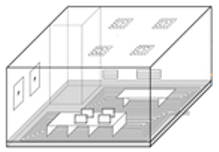
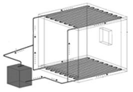
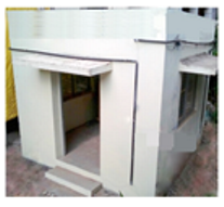
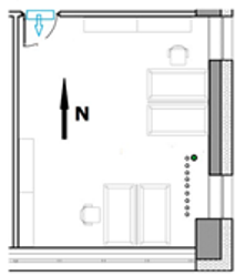
Review

A Review of Thermally Activated Building Systems (TABS) as an Alternative for Improving the Indoor Environment of Buildings

by
María M. Villar-Ramos
1,
Iván Hernández-Pérez
2,*,
Karla M. Aguilar-Castro
2,
Ivett Zavala-Guillén
3,
Edgar V. Macias-Melo
2,
Irving Hernández-López
4 and
Juan Serrano-Arellano
5
1
Doctorado en Ciencias en Ingeniería, División Académica de Ingeniería y Arquitectura, Universidad Juárez Autónoma de Tabasco (DAIA-UJAT), Carretera Cunduacán-Jalpa de Méndez km. 1, Cunduacán 86690, Tabasco, Mexico
2
División Académica de Ingeniería y Arquitectura, Universidad Juárez Autónoma de Tabasco (DAIA-UJAT), Carretera Cunduacán-Jalpa de Méndez km. 1, Cunduacán 86690, Tabasco, Mexico
3
Centro de Investigación Científica y de Educación Superior de Ensenada CICESE, Carretera Ensenada-Tijuana No. 3918, Zona Playitas, Ensenada 22860, Baja California, Mexico
4
Departamento de Ingeniería Química y Metalurgia, Universidad de Sonora (UNISON), Blvd. Luis Encinas y Rosales S/N, Col. Centro, Hermosillo 83000, Sonora, Mexico
5
División de Estudios de Posgrado e Investigación, Tecnológico Nacional de México/IT de Pachuca, Carretera Mexico-Pachuca km. 87.5, Colonia Venta Prieta, Pachuca de Soto 42080, Hidalgo, Mexico
*
Author to whom correspondence should be addressed.
Energies 2022, 15(17), 6179; https://doi.org/10.3390/en15176179
Submission received: 31 July 2022 / Revised: 19 August 2022 / Accepted: 21 August 2022 / Published: 25 August 2022
(This article belongs to the Topic Building Energy and Environment)

Abstract

:
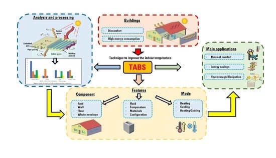
Among the alternatives for improving the thermal comfort conditions inside buildings are the thermally activated building systems (TABS). They are embedded in different building components to improve the indoor air temperature. In this work, a review and analysis of the state of the art of TABS was carried out to identify their potential to improve thermal comfort conditions and provide energy savings. Furthermore, this study presents the gaps identified in the literature so that researchers can develop future studies on TABS. The articles found were classified and analyzed in four sections, considering their implementation in roofs, walls, floors, and the whole envelope. In addition, aspects related to the configuration of the TABS and the fluid (speed, temperature, and mass flow rate) were analyzed. It was found that when TABS are implemented in roofs, walls, and floors, a reduction in the indoor temperature of a building of up to 14.4 °C can be obtained. Within the limitations of the TABS, the complexity and costs of their implementation compared to the use of air conditioning systems are reported. However, the TABS can provide energy savings of up to 50%.

Graphical Abstract

1. Introduction

According to experts from the Intergovernmental Panel on Climate Change (IPCC), climate change has impacted all countries [1]. The level of electricity consumption for thermal comfort has increased dramatically due to population growth. Moreover, in the last decade, significant changes in many meteorological phenomena and weather conditions have occurred in the world. It is estimated that the amount of energy consumed by the residential and construction sector in 2018 was 36%, of which 39% of the energy was related to CO 2 emissions worldwide [2].
A building is a construction or an enclosure made of different materials destined to be inhabited or destined to be used for conducting other activities. It is well known that most of the heat gains of the building envelope occur due to the received solar irradiance, the heat exchange with the outdoor environment, and its geometry and orientation. These heat gains or losses of the building envelope usually cause the inhabitants to use an air conditioning system to achieve thermal comfort. The scientific community has begun to search for and analyze construction alternatives that can reduce or increase thermal loads in buildings and reduce global electricity consumption through renewable energy [3,4]. Several construction alternatives to improve the indoor environment of a building are available, such as earth-to-air heat exchangers [5,6,7], ventilated roofs [8,9,10], reflective materials [11,12,13], passive design strategies [14,15,16], and thermally activated building systems (TABS) [17,18,19], among others. These design strategies also contribute to the proposal of intervention alternatives for the rehabilitation of spaces, considering the occupants, thermal adaptation, and energy use [14].
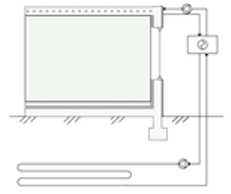
TABS can reduce heat gains or losses because of the heat exchange from embedded pipes installed in different building components. These pipes exchange heat directly with the thermal mass of the building and improve the temperature of the indoor environment [20]. Inside the pipes, water or air is generally circulated; these pipes are embedded in roofs, floors, or walls, depending on factors such as the climatic zone, orientation, and construction materials, among others. TABS are used to decrease or increase the temperature in the indoor space of an enclosure. The integration of the system with the construction structure allows the use of solar energy to be included, since the working fluid can be reused for other applications, helping to reduce pollution from greenhouse gases. According to the literature, the cost of implementing TABS is higher than traditional HVAC systems. However, the energy saving provided by TABS is 25% higher compared to the lifetime of a traditional air conditioning system. Using water as the working fluid in TABS increases energy savings because water can transport energy 3500 times more effectively than air. Among the advantages of using TABS over HVAC systems are: high indoor air quality, greater energy efficiency and smaller size, and low maintenance costs [21]. Although thermally activated systems have been studied, analysis of the envelope is required to obtain a better performance [22].
Various authors have analyzed the application of TABS, which have been referred to with different names depending on the application and the location in the building envelope. The literature is not consistent in labeling TABS. Table 1 summarizes the different names used for TABS.
TABS have been used for both heating and cooling and are located in different sections of a building envelope depending on their application. Previous review articles on TABS are available and discuss several aspects related to the thermal behavior of this technology. For instance, Rhee and Kim [23] analyzed the basic and applied literature on radiant heating and cooling systems embedded in the building envelope. The authors analyzed the main uses of radiant systems and thermal comfort, their cooling/heating capacity, obtained from different approaches such as computational fluid dynamics (CFD) analysis, energy simulation, system configuration, and control strategies for use at other times of the day. In the literature, TABS have also been analyzed according to their application, design, topology, and control strategies. Romaní et al. [24] analyzed TABS based on their application’s simulation and control strategies. The authors studied the system’s generalities and design and classified the TABS by mode of operation, position, and working fluid. Romaní et al. classified the TABS as radiant floor, radiant ceiling, hollow core slab, concrete core, and pipe-embedded envelope. Ma et al. [25] conducted a review of the state of the art of energy storage and dissipation in TABS. The authors focused on the extraction of energy from the indoor environment of buildings and how it can be reused in other systems. The authors concluded that by applying TABS correctly, an improvement in energy efficiency can be obtained. The possibilities and limitations of using TABS on walls were analyzed, such as in a work published by Krajčík and Šikula [26]. The authors examined the use of TABS and compared four types of wall cooling system. Krajčík et al. [27] carried out a review on TABS embedded in walls and their use as thermal barriers, with a focus on the reduction in thermal loads. The authors selected only systems with pipes embedded in the wall for heating and cooling. Krajčík et al. classified the wall system and the thermal barriers by their function, the configuration of material layers, and the location of the pipes. On the other hand, the analysis of TABS has also been considered in works incorporating insulation materials, such as phase change materials, as studied by Cai et al. [28], which contribute to improving the indoor environment and storing energy.
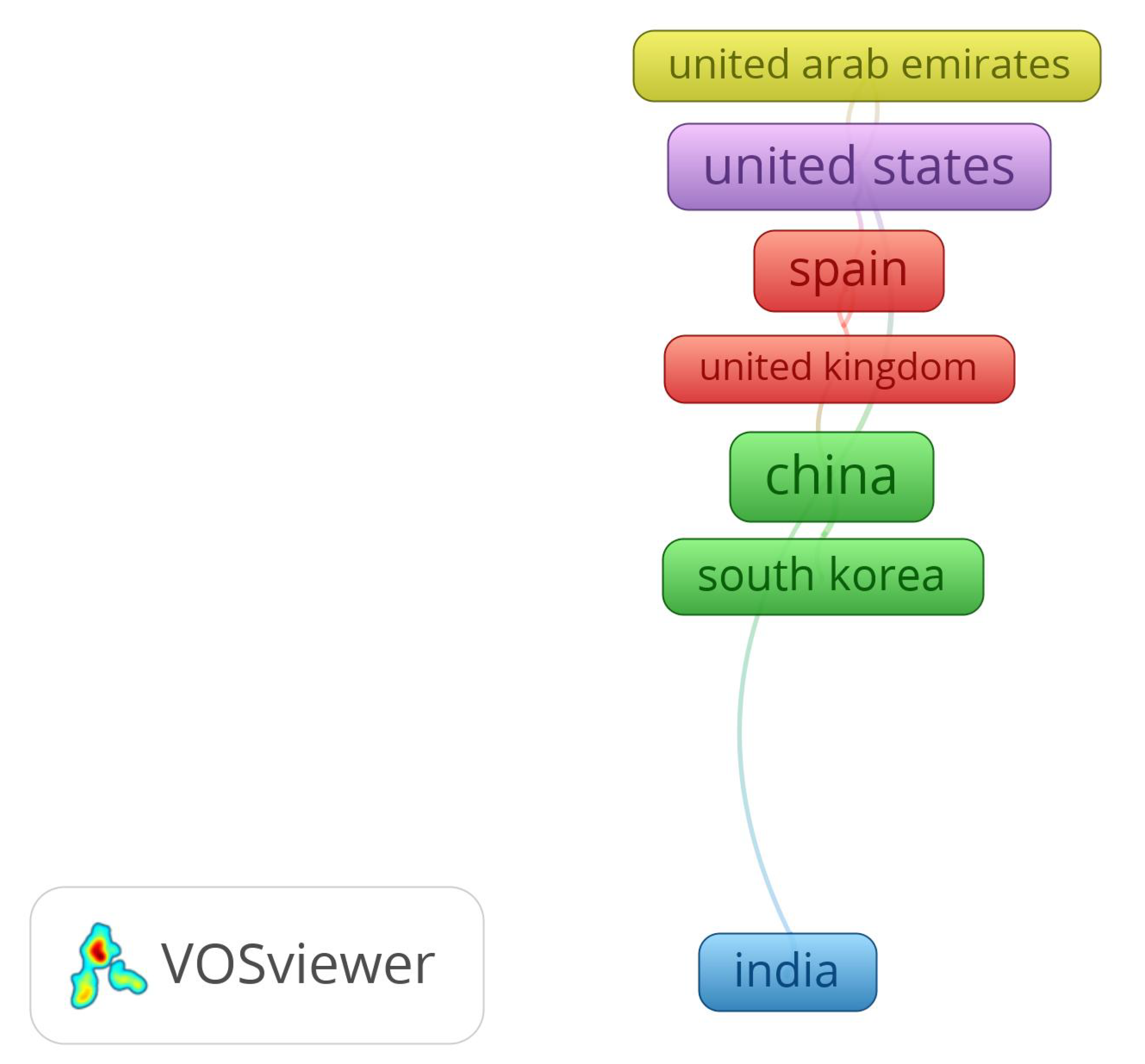
A bibliometric analysis was performed in order to explore the existing status of the literature on TABS. Figure 1 shows a visual map where some aspects of the selected articles were analyzed. To search for the term “Thermally Activated Building System”, the Scopus database was used by prioritizing the publication period from 2015 to 2022. To input the collected results, the open-source software VOSviewer, was used. It was found that the most cited topics in the literature related to the term were: (1) thermally activated, (2) cooling systems, (3) energy efficiency, (4) heat storage, and (5) thermal comfort. Figure 2 shows the countries of origin where the most articles about TABS have been published for the last seven years. TABS are being researched extensively in China, the United States, Germany, Spain, Belgium, and India, among others.
The present study aims to explore the state of the art of TABS in buildings and to present information that would help researchers to develop new practices, technologies, and research directions. The reviewed and analyzed articles were obtained mainly from databases such as Scopus, Web of Science, and Google Scholar by prioritizing the publication period from 2015 to 2022. Within the criteria for selecting the articles, only articles in which the heat exchanger tubes were embedded in a building envelope component (either roof, wall, or floor), or even in the whole building envelope, were considered. This work is divided into four sections, with the main findings highlighted when TABS are installed on roofs, walls, floors, and the whole building envelope. In each section, a summary table describes the applications of TABS in the building envelope, the type of climate studied, the mode of operation, the TABS features, and the simulation methods.

2. TABS Embedded in Building Roofs

Building roofs are usually the building components with the most significant temperature fluctuations, and they receive solar energy for more hours than any other component. Thus, in zones with a warm climate, building roofs are sources of unwanted heat that affect indoor thermal comfort conditions. This section focuses on the research works related to TABS integrated into building roofs. The improvements in thermal comfort, combinations with other technologies, and the energy savings provided by this technology are given in this section.

2.1. Potential of TABS to Improve Thermal Comfort When Installed in Roofs

The thermal comfort conditions inside buildings depend on variables such as air relative humidity, air temperature, and air speed, among others [29,30]. Several studies were conducted to determine the influence of roofs with TABS on the indoor air temperature of buildings, which can be considered as a method of assessing the thermal comfort improvements provided by TABS.
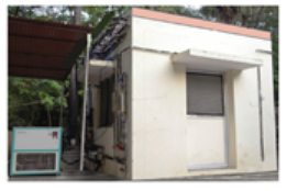
One of the first studies was that presented by Gwerder et al. [31], who proposed a control algorithm for TABS to comply with comfort requirements. The proposed method incorporates the change between the heating and cooling modes of the TABS to satisfy thermal comfort. The algorithm was tested in a simulation example. The hourly temperature analysis demonstrated that the TABS maintained the indoor air temperature between 21 and 27 °C for the whole year. Another control strategy for TABS in which the operating mode (heating or cooling) is determined by the average indoor air temperature was reported by Wit and Wisse [32]. They analyzed the thermal behavior of TABS with different hydronic typologies integrated into the roof of two office buildings. After several experimental tests, the results demonstrated that TABS could maintain the comfort conditions of the two buildings because most of the measured indoor air temperatures fell within the 80–90% satisfaction zones during the testing period. In another study of a roof integrated with TABS, Rey Martínez et al. [33] analyzed the indoor air quality and thermal comfort of a building. The building had four floors, TABS powered by a water chiller, and a cooling tower. The authors found that the operating temperature remained between 23 and 25 °C and the CO 2 levels at 850 ppm during occupancy. A simulation study of a building incorporated with TABS in the roof is described in Chung et al. [34]. EnergyPlus simulation software was used to apply different control strategies in each area of the case study building. The authors varied the water supply temperature from 19 to 25 °C in the interior zone and the perimeter for heating and cooling, grouping the tests into three case studies. Chung et al. concluded that by separating the proposed building into zones with different control strategies according to each floor’s needs, the thermal comfort improved by 5%. The experimental study presented by Dharmasastha et al. [35] analyzed the thermal behavior of a hybrid system integrated with a TABS coupled to a gypsum roof reinforced with fiberglass (TAGFRG). They built a test chamber with copper tubes of 0.01 m internal diameter embedded in the roof under hot and humid conditions in Chennai, India. The authors found that the TABS decreased up to 5.1 °C in the roof interior surface temperature and 6.7 °C in the indoor air of the test chamber. Saw et al. [36] studied the thermal behavior of a roof cooling system with a closed-loop pulsating heat pipe (CLPHP) and compared it with a bare metal roof system design. The authors proposed a rooftop CLPHP as an active cooling system for a tropical climate. This system consisted of a closed circuit of copper pipe, placed between two aluminum plates under a sheet roof and insulated on the lower surface. Methanol was used as a working fluid in the copper pipe circuit. They simulated solar radiation using two halogen lamps. Saw et al. found that a cool roof system with CLPHP reduced the indoor air temperature of the test cabin from 34 °C to 29.6 °C compared to the bare metal roof system.
Table 2 summarizes the studies presented in this section. The authors determined the influence of TABS installed in building roofs on thermal comfort by analyzing the indoor air temperature, satisfaction zone compliance, and comfort improvement percentage. The influence of TABS installed in roofs appears to be beneficial for increasing the thermal comfort in buildings.

2.2. Combination of TABS with Other Technologies for Roofs

Several research works analyzed the combination of TABS with other technologies to improve the indoor temperature of buildings. In the reported studies, TABS was combined with solar collectors, ground heat exchangers, and materials that favor energy storage. Wu et al. [37] developed a numerical model to analyze the behavior of a combined heating system formed by solar air collectors connected to a TABS with intermittent operation. The authors observed that the solar air collector inlet temperature ranged from 17 to 24 °C, while the air collector outlet temperature ranged from 35 to 62 °C, with an average efficiency of 47.1%. They concluded that with the proposed system an acceptable thermal comfort temperature could be maintained inside the building ranging from 17 to 24 °C. In a recent study, Chung et al. [38] simulated the behavior of a coupled system (TABS + ground heat exchanger) considering 28 climatic conditions and varying the burial depth of the ground heat exchanger. The authors found that the coupled system removed the peak thermal loads by up to 75%, while a chiller cooling system removed it by 32%. They also found that in this coupled system, the climatic conditions caused variations in the load-handled ratio, obtaining better results in warm humid climates when the depth of the ground heat exchanger was buried at 2 m.
Other authors studied the combination of TABS with phase change material (PCM). A study of roofs with PCM and TABS is also available. Yu et al. [39] studied a roof with embedded tubes through which air circulated. They validated and compared through a CFD numerical simulation the thermal properties of the system with a PCM as insulation. The authors proposed a concrete roof with a thickness of 0.19 m and a layer of 0.03 m of paraffin as the PCM. The results show that the optimum phase transition temperature increases linearly by approximately 2 °C when the average temperature of the outdoor air rises. Compared to a roof without PCM, they found that the interior surface temperature decreases by between 3.7 and 4.0 °C in different regions of China. In a more recent study, the same authors [40] proposed a ventilated roof model with embedded pipes and a stabilized layer of PCM (VRSP). The authors developed a steady-state three-dimensional heat transfer model of the VRSP system in ANSYS FLUENT. The convective heat transfer coefficient on the interior surface of the roof was 8.72 W m 2 K 1 and 23.26 W m 2 K 1 on the exterior surface, and the indoor air temperature was set at 26 °C. The effect of the phase transition temperature, the thickness of the PCM layer, and the airflow rate in the tubes was studied. The researchers found that the optimal design of the roof had a phase transition temperature of 29–31 °C, a thickness of the PCM layer of 0.02–0.35 m, and an airflow rate of 1.4–2.5 m s 1 . It was shown that the optimum design reduced the average temperatures of the interior surface by a factor ranging between 0.4 and 3.2 °C compared to the non-ventilated roof. Moreover, the daily heat gain of the roof was reduced by a factor ranging between 9 and 82%. In a recent study, Heidenthaler et al. [41] performed a comparative analysis of TABS embedded in concrete and wooden roof slabs. The authors used the finite element analysis (FEA) simulation software HTflux. They analyzed four basic variants of fir and beech wood, of which they obtained five additional combinations. They also varied the depth at which the tubes were embedded (0.03 and 0.06 m). The authors concluded that by using wood in TABS, adequate heat flux densities can be achieved for heating in low-energy buildings, supplying the fluid at higher temperatures compared to concrete structures. The authors found that the basic combination of beech (radial/tangential) with 6 cm embedded pipes has a potential energy storage capacity 53% greater than a concrete structure. Other authors that analyzed the behavior of a roof TABS coupled with a ground source heat pump (GSHP) were Hu et al. [42]. The authors carried out an energetic and exergetic analysis of a building for summer and winter. The authors found that adding a cooling tower improves system performance with an efficiency of up to 16%, maintaining the indoor ambient temperature within the range of 18–26 °C.
Table 3 summarizes the studies presented in this section. The coupling of TABS with other technologies such as solar collectors or ground heat exchangers is expected to increase the cooling or heating effect that TABS provides. Such a combination of technologies demonstrates that TABS can be integrated into renewable energy sources and will help to reduce the emission of greenhouse gases. Moreover, as mentioned above, the combination of TABS with other technologies such as PCM increases the thermal mass of the building roofs, which enhances the peak indoor air temperature reduction.

2.3. Potential of TABS to Reduce the Energy Consumption When Installed in Roofs

The reduction in the energy consumption of air-conditioned buildings due to the incorporation of TABS in building roofs was analyzed in two research works. In the first work, Lehmann et al. [43] investigated the functionality and application range of a TABS by simulating a typical office in TRNSYS. The authors analyzed thermal comfort aspects, maximum allowable heat gains in the room, and the re-cooling of the building mass. They studied a building that was 6 m long, 5 m wide, and 3 m high facing west. This room had pipes of 0.020 m internal diameter embedded in a 0.3 m-thick concrete roof slab and a 0.25 m separation between pipes. It was found that the maximum allowable total heat gains were 39 W m 2 with carpet in the room and 32 W m 2 with a false floor, with a room temperature between 21 and 24 °C. Furthermore, the authors found that the TABS reduced the energy consumption for cooling by 50% compared to the base case. The second study is a simulation study mentioned in Section 2.1. Chung et al. [34] also estimated the influence of the TABS installed on the roof on the thermal loads of the building prototype. They found that compared to the reference case, the heating load was reduced by 10%, the cooling load was reduced by 36%, and the total energy consumption decreased by 13% due to the TABS. Table 4 summarizes the studies presented in this section, where the authors demonstrated the potential of TABS for reducing energy consumption and reducing heating and cooling loads.

3. TABS Embedded in Building Walls

The walls of a building are another type of building envelope component that exchange energy with the outdoor environment because of their significant surface area. Several studies about TABS on building walls have been carried out. TABS embedded in walls is a potential solution to improve their thermal behavior by increasing or decreasing heat losses and saving energy. The aim of this section is to introduce the simulation methods to predict the behavior of TABS, the most suitable configuration, and other techniques to improve the design and construction of TABS.

3.1. Influence of the Flow Characteristics on the Thermal Behavior of TABS Embedded in Walls

Some authors have carried out experimental studies with TABS in walls, where they have varied the fluid parameters such as inlet temperature and fill ratio to analyze the thermal behavior of building walls with TABS. Zhu et al. [44] proposed a two-phase thermosyphon loop (TPTL) incorporated into a thermally activated wall and tested it under winter conditions. The authors carried out experimental tests using a test wall 1 m wide, 0.9 m, high, and 0.2 m thick with embedded tubes of 0.009 m internal diameter, using ethanol as a working fluid. The authors varied the fluid temperature from 25 to 65 °C and the fluid fill ratio from 60 to 144%. The authors found that the fill ratio between the volume of the working fluid and the evaporator volume has a critical impact on the thermal resistance and the starting behavior of the TPTL. They found that the optimal fill ratio is around 116%. A theoretical–experimental study of pipes embedded in a wall for analyzing the influence of pipe depth and spacing on the indoor temperature gradient was carried out by Romaní et al. [45]. They installed an experimental prototype in Spain, which measured 2.85 × 1.85 × 1.95 m. The prototype walls were made of alveolar brick, with 0.016 m-diameter polyethylene tubes embedded 0.036 m from the interior surface and a 0.15 m separation between each pipe. The experimental results obtained by the authors show that the indoor temperature near the east, west, and south walls remains between 25 and 31 °C.
Table 5 summarizes the articles about wall-embedded TABS and the influence that the working fluid has on thermal behavior. As can be seen, TABS does not only use water as the working fluid.

3.2. Prediction of the Behavior of TABS Embedded in Walls

Some works have analyzed the thermal behavior of building walls with TABS by modeling the system. The authors have analyzed the system using different methods such as resistance–capacitance (RC), the number of transfer units (NTU), and finite difference (FD). Fluid parameters such as inlet temperature, inlet velocity, and mass flow rate were analyzed. Some of these studies have been validated with experimental data, such as that of Todorović et al. [46]. The authors used the analytical expression of Faxen-Rydberg-Huber to determine the thermal characteristics of walls heated by embedded tubes. This expression was experimentally and theoretically verified using three heated wall panels with different structures and geometric characteristics. The panels operated in heating mode, the temperature of the water from feeding the pump was set at 40 °C, and the volumetric flow circulated at 2 L min 1 . The authors compared measurements of the average surface temperature of the panels, using a test contact, thermistors, and a thermal imaging camera. The differences between the average temperatures of the panel surfaces were 1.8 to 4.5% when measured using a non-contact and contact method. The authors concluded that the difference between the analytically calculated average temperature and the experimental measurements is 13.7 and 8.6% by contact and non-contact methods, respectively. A model of the frequency-domain finite difference (FDFD) of the thermal behavior of a building wall construction was developed by Xie et al. [47]. The researchers built a test room to validate the model, being 5.6 m long, 3.3 m wide, and 2.8 m high, divided into two test chambers by a 0.31 m-wide wall. The experimental test had embedded polypropylene tubes of 0.02 m diameter placed with a separation of 0.2 m. The authors varied the water inlet temperature to 17.5, 19, and 20 °C, while the water inlet velocity was set at 0.5 m s 1 . They found that by supplying the water in the tubes at 17.5 °C, a heat exchange with the wall internal surface of 25.5 W m 2 could be obtained. The results show that the finite difference model could predict the behavior of construction with embedded pipes. The relative errors were 6.5% and 4.4% between the measurement and the prediction by the FDFD model for the external surface heat flux and the pipe-embedded building envelope internal pipe surface heat flux, respectively. In other research by the same group, Zhu et al. [48] developed a semi-dynamic thermal model of an active pipe-embedded building. The model consists of construction with embedded pipes in a 3 m-high and 2 m-wide wall. This model was coupled with a resistance and capacitance model (RC) that predicts heat transfer along the width of the structure and a number of transfer units model (NTU) to evaluate heat transfer in the pipes. To assess the behavior of the semi-dynamic model, they developed a CFD model in FORTRAN that functioned as an experimental virtual test for comparison. They tested and verified three case studies where the water inlet temperature was set at 20 °C, varying the water inlet velocity from 0.5 to 0.7 m s 1 and the thermophysical properties of the wall; the pipe spacing was 0.02 m. The authors observed that the changes in the heat fluxes taken away by the water are not obvious with different velocities in the water. Meanwhile, an average difference of about 0.5 °C in the outlet temperature of the fluid was found throughout the day. The results demonstrate that the semi-dynamic model predicts the thermal behavior of a TABS with a relative error of 5%. Later, Zhu et al. [49] validated a simplified semi-dynamic model of a chamber with tubes embedded in the envelope. They built two chambers with a controlled environment to perform the validation, one with pipes embedded in the envelope and the other without embedded pipes as a reference. The walls of the chambers were made of alveolar brick, with a layer of cement mortar covering both surfaces of the walls, with polybutylene tubes of 0.020 m in diameter embedded in the layer of cement mortar. The water velocity was varied from 0.8 to 0.5 m s 1 , and the water temperature from 18 to 19 °C. The authors concluded that the difference between the model and the experimental validation was minimal. The average relative error to predict the outlet water temperature was less than 0.10 °C, while the heat transferred to the water had a difference of 11%. Other authors that varied the flow rate with a numerical model were Ibrahim et al. [50], who analyzed the behavior of the surface temperatures and the fluid of a chamber with TABS in the walls through which water circulated. To compare the experimental results with the numerical model, they used two chambers: a reference sample, and the other as a test. The experimental chambers measured 2.25 × 1.6 × 1.2 m (length, width, and height), composed of concrete walls with a thickness of 0.12 m with a layer of 0.04 m aerogel plaster. The copper pipes were embedded in the aerogel plaster and placed in a serpentine shape, with a separation between pipes of 0.10 m. The authors used a mixture of 60% water and 40% antifreeze as the working fluid, with a variable volumetric flow rate of 5.53–11.6 L h 1 controlled by a pump in a closed circuit. The authors found that the performance of the wall with TABS is affected by the weather, the indoor temperature, the solar absorptivity of the envelope, and the mass flow rate. Qu et al. [51] investigated the relationship between the design and the operating parameters of a thermally activated wall system (TAW) using a mathematical model developed in COMSOL and validated with experimental data from a test chamber. The variables analyzed were the separation between each tube, the area of the thermally activated wall, the flow rate, and the inlet temperature of the water. The authors proposed optimal design graphics for a thermally activated wall system for China’s climatic zones. The test chamber measured 2 m × 2 m × 2 m, and was thermally activated on the south wall with embedded tubes, where three separations between tubes (0.01, 0.02, and 0.03 m) were tested. The water flow circulating through the TAW had a velocity of 0.2 m s 1 , and a heat pump supplied three different temperatures (15, 17, and 19 °C). The results indicate that the water inlet temperature and the indoor air temperature affected the heat transfer of the TAW. They found that the maximum inner wall surface temperature occurred for a separation between tubes of 0.02 m and a water velocity of 0.2 m s 1 , and the maximum and minimum values reached 1.78 °C and 1.80 °C during the cooling and heating mode.
Other studies have analyzed the effect that the arrangement, the separation and the distance between the pipes have on the indoor temperature. Jiang et al. [52] investigated the influence of the velocity and the type of arrangement on the performance considering the changes in the water temperature. They compared two TABS arrangements in a numerical study: a serial pipe-embedded wall (SPW) and a wall with embedded tubes connected in parallel (PPW). The authors found that the inlet water temperature had a more significant effect on the interior temperature than the sol-air temperature. The authors observed that reducing the water temperature below 26 °C in summer and increasing the temperature above 18 °C in winter reduced the cooling and heating thermal loads. Romaní et al. [45] made a numerical model of a radiant wall in 2D, validated with an experimental prototype. The radiant wall was simulated using the finite volume method (FVM). The parametric study showed that the separation and the depth at which the pipes are placed significantly influenced the walls’ thermal behavior. The authors obtained better performance when placing the pipes at a depth of 0.045 and 0.065 m and with a separation of 0.0125 and 0.0150 m because the heat fluxes and the temperature inside are minimized.
Table 6 summarizes the articles about models developed for TABS embedded in walls. Among the variables analyzed are the fluid supply velocity, the fluid inlet temperature, and the configuration of the pipes that supply the fluid. As can be seen, TABS are mostly used for heating and use water as the working fluid. Furthermore, TABS have different arrangements and configurations depending on the building construction methods.

3.3. Heat Losses and Heat Dissipation of Walls Integrated with TABS

A building wall integrated with TABS can reduce the heat losses of buildings in winter. Ibrahim et al. [50] found that heat losses were reduced by between 9% and 35% in the Mediterranean climates when a wall with embedded pipes was used. On the other hand, a building wall integrated with TABS can dissipate heat more effectively than a conventional wall. Li and Zhang [53], analyzed the behavior of a wall implanted with heat pipes (WIHP). The authors compared the WIHP with a conventional wall in the summer months in Tianjin, China. The WIPH wall dimensions were 1.72 m long, 1.72 m wide, and 0.34 m thick, with 24 capillary tubes of 0.002 m in diameter and a length of 0.60 m. The authors concluded that the WIPH system had a greater heat dissipation effect in the summer. Its heat transfer capacity was 50.7 kW m 2 , and the average temperature of the WIPH was 2 °C lower than the conventional wall. Other authors, such as Iffa et al. [54], included the use of an insulating material for energy storage and saving. The authors coupled an active insulation system with a TABS embedded in a wall. They analyzed the behavior of the system through simulation and experimental tests. It was found that if both systems are coupled, a flux of up to 81.92 W m 2 can be transferred from the wall to the air. Thermal barriers were proposed by Krzaczek et al. [55] to maintain the changes in the internal energy of the walls at a level close to zero. They proposed a thermal barrier model in residential construction, which consisted of a system of tubes embedded in the walls to heat or cool a building, controlled by a fuzzy logic program. The pipes were supplied by water without antifreeze at 25.3 °C for summer and 20.5 °C for winter. The experimental test period was 17 months. They found that the control method through the thermal barrier system was efficient for maintaining a comfortable temperature inside, finding that the temperature variations in the exterior and interior wall of construction were less than 1 °C.
Table 7 summarizes the studies presented in this section. These research works indicate that walls integrated with TABS allow heat gains to the indoor of buildings to be reduced. However, it is important to analyze the most suitable configurations to increase heat dissipation, because a reduction of 2 °C in the case of the study reported by Li and Zhang [53] could be considered low if the complexity of the installation of the TABS on the walls is considered.

3.4. TABS Walls and Other Techniques for Energy Saving

The TABS is studied for its capacity to improve buildings’ indoor thermal comfort; some authors have proposed integrating new insulating materials and techniques to control the system. Comparing two TABS arrangements in a numerical study, Jiang et al. [52] found that the energy load reduction rate of a serial pipe-embedded wall (SPW) system is higher (25.2%) than that of a wall with embedded tubes connected in parallel (PPW) (8.7%). The influence of the TABS on heating energy consumption in a typical Serbian home was determined by Stojanović et al. [56]. The authors simulated a TABS in EnergyPlus. The TABS was fed with groundwater, where three supply temperatures were used: 10, 14, and 18 °C. The authors concluded that when the TABS is used for heating, energy savings of up to 75% can be obtained with a supply temperature of 18 °C. Furthermore, they emphasized that all renewable sources can be used as an energy source for the TABS when it is used for heating. Guerrero et al. [57] proposed a new prefabricated panel for residential building facades. The authors proposed the integration of phase change materials (PCM) and concrete as structural elements. In this structure, water circulates through heat exchange pipes embedded in mortar cement, made of plastic material with an outer diameter of 0.01 m and a separation of 0.10 m between the pipes. The inlet water temperature and the distance between pipes were varied, from 30 to 45 °C and from 0.08 to 0.12 m, respectively. The authors concluded that the system design depends on the meteorological conditions; if it is designed for winter, a phase change temperature around 24 °C is required. If it is used for summer, the required phase change temperature is around 20 °C. The efficiency was reduced to 6% when the distance increased from 0.08 m to 0.12 m. On the other hand, the efficiency reached approximately 7% with the increasing inlet water temperature of 45 ºC. Chen et al. [58] also proposed a thermo-activated PCM composite wall (TAPCW). The TAPCW consisted of placing an intermediate layer with tubes embedded in a macro-encapsulated PCM on the outer side. The authors used a validated numerical model to study the thermal and energy-saving performance of TAPCW under winter weather conditions in northern China. The authors analyzed different values for the spacing between each tube, the thickness of the PCM, and the orientation. The parametric study showed that the separation between pipes has a more significant influence on the system than the thickness of the PCM. They found that a separation between pipes of 0.01 m could be used for the thermal barrier function and a separation between tubes of 0.075 m for the heating function. The researchers also found that the TAPCW oriented to the north was more effective because it had an interior temperature increase of up to 1.8 °C and reduced energy consumption by 65%. Guerrero Delgado et al. [59] characterized and evaluated a panel designed for facades with an integrated TABS. As a first stage, the authors studied the behavior of the TABS through modeling in ANSYS FLUENT operated under different climatic zones. In the second stage, the authors integrated the TABS into a building using a simplified model to evaluate the energy demand and the system energy-saving potential. Guerrero Delgado et al. concluded that the proposed TABS is fully compatible with renewable energies, showing that energy savings of up to 40% for heating can be obtained. Kisilewicz et al. [60] present preliminary results of the thermal behavior of a thermally activated wall coupled with a ground heat exchanger. The authors compared an actively insulated wall against a reference wall under Hungarian climatic conditions. The thermally activated insulated wall construction consisted of a concrete layer on the outside, a layer of extruded polystyrene, tubes embedded in reinforced concrete, and an interior layer of extruded polystyrene. As working fluid in the embedded tubes, in summer, they used refrigerant at a lower temperature than that of the indoor air and a temperature higher than that of outdoor air in winter. The authors concluded that thermally activated insulation significantly improves the exterior wall’s insulation parameters because, in the periods analyzed, they obtained a reduction in total energy loss through the external walls from 53 to 81%. To control the water supply temperature in the system, Qu et al. [61] proposed a model for the heat transfer of a TABS in walls under the climatic conditions of Beijing, China. The authors built a test chamber to validate the energy consumption and simulated indoor temperature in EnergyPlus. The test cabin had the following dimensions: 0.8 m long, 0.8 m wide, and 0.8 m high. It had embedded tubes of 0.02 m in diameter and separation between pipes of 0.05 m. The results indicate that pre-cooling a room overnight and reducing the water supply temperature can improve thermal comfort and reduce the unit capacity by over 35%. Kalús et al. [62] proposed the design of a thermally activated precast panel. The authors presented the development of a facade system, through calculations and a parametric study of the system for heating and cooling mode. They discovered that a number of variables, including pipe diameter, distance between the pipes, pipe dimensions, mean heat transfer medium temperature, and the heat storage capacity of building structures, affect the thermal and cooling performance of thermal insulation panels.
Table 8 shows the main works on thermally activated walls. These studies analyzed the behavior of TABS by changing parameters such as fluid velocity, temperature, and the location of the pipes, among others. These changes resulted in energy savings from 40 to 75%. Furthermore, by adding a layer of PCM to the TABS wall system, it is possible to obtain up to 65% energy savings.

4. TABS Embedded in Floor

This section focuses on TABS installed in the floor, their configurations, and materials used to improve the thermal comfort of the buildings.

4.1. Strategies for Improving the Behavior of TABS Embedded in Floors

Some authors have chosen to analyze floor TABS by simulating their behavior to improve thermal comfort [63]. Joe and Karava [64] developed a model predictive control (MPC) to optimize its behavior, reduce energy consumption and costs, and increase thermal comfort. The authors compared simulated and experimental data from three buildings in heating and cooling mode: (1) with a hydronic radiant floor system, (2) with a wall diffuser, and (3) with a roof diffuser. The authors found that significant energy and cost reductions were achieved compared to a traditional HVAC system. The cost savings were close to 34%, and the energy savings were 16%. Meanwhile, the building with the radiant floor system obtained energy savings of 50% and 29% compared to buildings 2 and 3. In the case of Feng et al. [65], they analyzed the impact of solar radiation on floor cooling in order to find the cooling load of the proposed system. The authors modeled the system in Energy Plus with a total of 864 simulations. The authors found the floor cooling capacity to be 35.6–44.0 W m 2 at an operating temperature of 24 °C. Yang et al. [66] analyzed the behavior of a radiant floor heating system embedded in concrete. The authors analyzed the behavior of the system by simulating different scenarios in Modelica. The separation between tubes (100–500 mm), the thickness of the concrete (50–190 mm) and the temperature of the water supply (35–60 °C) were varied. The authors found that by supplying a water temperature of 35 °C, the indoor temperature was kept below the comfort temperature. However, increasing the separation between tubes and supplying a higher temperature increased the thermal comfort. With respect to the thickness of the concrete, the authors found that by increasing the thickness, fewer disturbances were obtained in the indoor air temperatures, but the energy consumption of electricity increased.
Some authors have analyzed the behavior of TABS using different construction materials on the floor. To analyze its thermal behavior and the ability to store heat, Ma et al. [67] proposed a radiant floor with embedded pipes. The authors analyzed the thermal behavior of the radiant concrete panel experimentally and with a simplified model. They compared two concrete blocks with aluminum-plastic (XPAP) embedded pipes, where one block had aluminum fins attached to the bottom surface of the pipe and another block had embedded tubes without fins. Inside the pipes, water was circulated at three different temperatures, 25.0 °C, 29.8 °C and 34.6 °C. The authors found that the radiant floor with aluminum fins reduced the temperature through the concrete block and improved energy storage, increasing exponentially with increasing fin height. The authors concluded that the height and material of the fins integrated into the tubes have a significant effect on the energy storage rate. Other authors that analyzed the effect of varying construction materials on the behavior of TABS were Pardo et al. [68]. The authors developed an RC model of a TABS embedded in the floor and compared two types of materials as a cover, granite and wood. The authors analyzed 216 dwellings, where they varied the location, glazing, insulation, heat capacity and orientation. The authors found that wooden floors can offer a good performance when compared to materials with high thermal conductivity. With wood as floor covering, a 6.4% reduction in energy demand and a 1.4% reduction in comfort hours were obtained.
Table 9 summarizes the studies that analyzed the behavior of TABS in flats. The various authors have not only analyzed the behavior of TABS, but have also varied the construction materials. It can be seen that most of the works were carried out for heating, varying the configuration.

4.2. Combination of TABS with Other Technologies for Floors

Floor TABS have also been coupled with other systems in order to improve system efficiency and thermal performance. Park et al. [69] conducted a study to estimate the thermal comfort and energy consumption of a TABS combined with a radiant floor heating system (RFHS) and an air conditioning system package (PAC). The authors performed the analysis using simulations from EnergyPlus of a conventional residence construction and a low-thermal-load residential construction, in which they proposed 17 different combinations. The authors found that combining TABS with other systems showed better thermal comfort. However, the configurations TABS-PAC and TABS in cooling mode maintained the indoor comfort conditions. The authors suggested that the TABS should be operated under pre-cooling conditions considering the occupancy and cooling load of the building. Cen et al. [70] experimentally compared the behavior of a radiant floor system with a fain coil. The authors analyzed the influence of the size of the space on thermal comfort, using a variable space height of 3, 5, 7 and 9 m. The authors found that the indoor air temperature is similar using either of the two systems when the height of the room is 5, 7 and 9 m, with a temperature of 20.8 to 25.4 °C. However, they found that the air velocity is lower at all heights when using a radiant floor system (0.03 to 0.04 m s 1 ) than when using a fan coil (0.09 a 0.12 m s 1 ). The authors concluded that the thermal comfort is better with a radiant floor system when the size of the space is lower. Zhang et al. [71] combined radiant floor cooling with an underfloor ventilation system (RFCUV). The manuscript focused on developing a dynamic model for radiant floor energy savings compared to the proportional integral derivative model. The water supplied to the radiant floor was 22 °C to 24 °C. The authors found that the system had an energy saving of 17.5%, 8.2% for the air-cooled chiller and 20.5% for the air handling unit. The behavior of a composite hybrid radiant floor was evaluated by Gu et al. [72] in a hot and humid climate. The authors proposed four case studies where they combined the floor coil, fan coil and outdoor air unit in an office divided by zones. The water was supplied to the tubes by means of an air source heat pump in a temperature range of 7 °C to 45 °C. The best case was the one with the combination of the four elements, with a surface temperature of the floor that dropped to 22.8 °C, a relative humidity from 52.1 to 59%, and an average floor heat flux of 60 W m 2 . A study of radiant floor heating was conducted by Hwang et al. [73]. The authors performed a simulation of a radiant heating floor assisted by air source heating systems in residential buildings, increasing the floor temperature by 1 °C (20–25 °C). The authors found that there are greater energy savings (59.2%) when only the air heat pump works and the floor temperature is lower (20 °C), whereas when only the radiant floor works, the temperature increases (25°C), thermal comfort decreases, and there is no energy saving. When the radiant floor is assisted by the heat pump, energy savings of 19.6% to 37.6% are obtained. In the case of Sharifi et al. [74], an algorithm was developed to determine the optimal load split of a hybrid TABS. The floor TABS was coupled with a ground source heat pump. They used a design methodology that guaranteed thermal comfort and a reduction in energy use. The authors analyzed the behavior of the system and found that the proposed algorithm reduced the cooling demand by 45% and the heating energy demand by 38%. Authors such as Zhu et al. [75] experimentally analyzed the coupling of a radiant floor and a fan coil cooling (RFCAFC) system in a place with a humid climate. The tubes were made of PE-RT and embedded in a concrete floor with polystyrene insulation and mortar. The system had the ability to automatically change the temperature of the fluid depending on weather conditions. The authors analyzed three different climatic conditions: (1) low temperature and high humidity; (2) high temperature and low humidity; and (3) average temperature and humidity. Zhu et al. found that the fan coil can reach 73.8% of the proportion of the cooling load. The case study with medium temperature and humidity consumed 11.36 kWh 1 , 15.4% less energy than the case with low temperature and high humidity. With this coupling the authors were able to maintain the soil surface temperature at 23 °C. Ren et al. [76] carried out an experimental analysis of radiant floor cooling (RFC) with a floor cooling source and displaced ventilation. The authors implemented control strategies with intermittent operation of the system and varying the speed and supply of water flow in the tubes, according to climatic conditions. The authors suggested that there should be a pre-cooling time to reduce the temperature inside the construction. With the proposed control strategies, the surface temperature of the floor decreased to 23.6 °C, with a difference of 4 °C between the radiant temperature and indoor air.
The floor studies presented in this section are summarized in Table 10. The table indicates that floor TABS have also been coupled with other systems in order to save energy and reduce the indoor temperature of buildings.

5. TABS Installed in Several Building Components

In this section are presented the TABS studied to decrease or increase the indoor temperature of buildings when they are installed in more than one building component, and in some cases, TABS was coupled with other technologies. Authors around the world have analyzed different parameters and scenarios with TABS and some have evaluated the utilization of TABS in the whole building envelope.

Indoor Temperature Behavior of Buildings with TABS Installed in Several Building Components

TABS has been analyzed to decrease or increase the temperature of indoor buildings. These systems can be embedded in one or several building envelope components and can be coupled with other technologies. Khan et al. [77] used a TABS embedded in the roof and floor working in cooling mode. The authors performed simulations using MATLAB and EnergyPlus to evaluate the thermal behavior and the energy-saving potential of TABS. The models were calibrated and validated with experimental data. The authors proposed two cases: one with a conventional air-cooling system and one with the proposed TABS. The authors found that the TABS provided up to 30% of energy savings compared to the traditional system. Leo Samuel et al. [78] studied a hybrid passive cooling system, which consisted of a cooling tower connected to a TABS. The system was proposed for five different climatic regions in twelve cities in India. The authors used COMSOL Multiphysics software to perform simulations of the hybrid cooling system. They compared different scenarios, such as floor and roof cooled TABS (RF) and all-surface cooled TABS (AS), in terms of cooling performance for various climatic zones. They concluded that TABS (RF) configuration in arid climates reduced the indoor air temperature up to 9.5 °C and the TABS (AS) configuration up to 14.4 °C. In contrast, in humid tropical climates, the reductions reached up to 4.4 °C and 6.6 °C, respectively. Later, Leo Samuel et al. [79] carried out a study using CFD and analyzed a TABS with embedded pipes in the roof and floor. In these pipes, they circulated water with outlet and return from a cooling tower. To validate the model, they built a prototype of dimensions 3.46 × 3.46 × 3.15 m, with a roof and floor thickness of 0.15 m. The authors found that the TABS maintained an indoor air temperature between 23.5 and 28 °C.
Some parameters were varied by Leo Samuel et al. [80] to analyze the thermal behavior of TABS. The authors numerically and experimentally analyzed the influence of three parameters: spacing, vertical position, and the arrangement of pipes embedded in the roof and floor. They found that by reducing the separation between pipes from 0.3 to 0.1 m and moving the pipes to the direction of the interior surface from 0.135 to 0.015 m reduced the indoor air temperature by between 1.6 and 2.7 °C, respectively. Meanwhile, changing the arrangement of the pipes from coil to parallel reduced the indoor air to 32.1 °C. The authors reached such reductions with a separation of 0.1 m, and a vertical position of 0.015 m, and a parallel arrangement of the pipes reduced the indoor air temperature by up to 6.8 °C, reaching a comfort temperature of 29°C in semi-arid weather. In the same year, Leo Samuel et al. [81] simulated the performance of TABS under a warm weather scenario. The authors used COMSOL Multiphysics to analyze the influence of the temperature and inlet velocity of water and the number of components with TABS for cooling. The CFD model was validated using experimental data from a previous study of the authors. The researchers found that the parameter that had the most significant effect on thermal comfort was the number of cooling surfaces. They showed that if all the room surfaces are cooled, with a flow of 19 L h 1 of water, it reduced the average indoor temperature by up to 5.7 °C. The same authors, Leo Samuel et al. [82], performed experimental tests of a scale room with a thermally activated construction system, using water pipes embedded in concrete in the roof, floor, and walls, with separate water flow controls. The experimental prototype measured 3.5 × 3.5 × 3.15 m with a 15 cm-thick reinforced concrete slab, surrounded by trees and structures that provided partial shade. They used ½” schedule 40 PVC pipes, with a 10 cm separation between pipes. They studied temperature, relative humidity, air speed, and water flow through the pipes. The authors found that if only the cooling is activated on the roof, the indoor temperature remained around 33.1 °C. However, when the cooling is activated on the walls, floor, and roof, the temperature decreases to 29.2 °C. The authors concluded that this system, coupled with a passive ventilation system, increases its feasibility in climates with unfavorable conditions and works with a fluid at relatively high temperatures. To study the internal diameter of the heat exchanger pipes, the thermal conductivity of the pipes, and the thickness of the roof slab and floor, Leo Samuel et al. [83] analyzed the influence of those parameters of TABS on thermal comfort. They used a model built into COMSOL Multiphysics that was validated using experimental data obtained in the authors’ previous work. They concluded that increasing the thermal conductivity of the pipes from 0.14 to 1.4 W m 1 K 1 considerably improves the cooling performance of the system. They found that the best combination of features studied was an internal diameter of the pipe of 0.0017 m, a thermal conductivity of the pipe of 0.14 W m 1 K 1 and a thickness in the roof and floor of 0.2 m. This combination reduced the indoor operating temperature by 4.7 °C. Michalak [18] carried out measurements and analyzed a TABS implemented in a building used as the primary heating and cooling source. The TABS was coupled with additional heating and cooling units such as fan coils, floor heating and air handling units (AHUs). The measurements were carried out during four months in an office with periods of occupation. The measurements were focused on variables such as indoor air temperature and the temperature of the floor. The authors also calculated predicted percentage of dissatisfied (PPD) and predicted mean vote (PMV). The average soil surface temperature was between 20.6 and 26.2 °C, while the average vertical air temperature was from 22.5 to 23.1 °C, the PMV ranged from 0.52 to 1.50, and less than 30% of the people expressed thermal dissatisfaction. The system analyzed by Michalak had 1275 kWh of exchange energy for cooling and 2500 kWh for heating. The author concluded that implementing a TABS with mechanical ventilation systems improves the thermal comfort conditions of an office. Other authors that conducted an experimental study of a hybrid TABS were Dharmasastha et al. [84]. They carried out an analysis of a TABS coupled with a gypsum roof reinforced with fiberglass (TAGFRG), where they varied the supply temperature of the water that passed through the pipes embedded in the roof, walls, and floors. The authors found that by decreasing the supply water temperature from 26 °C to 18 °C, the interior surface temperature of the roof can decrease by as much as 5.8 °C. However, the authors found that cooling just the roof of the building only lessened the effects that the outside ambient temperature had on indoor air temperature fluctuations. On the other hand, they found that if water was recirculated throughout the whole envelope of the test chamber, the thermal comfort increased, with a satisfaction percentage of 90%. Montenegro and Hongn [85] carried out a parametric study of TABS using a numerical model. The authors used experimental data from previous works to validate the model and subsequently compared the thermal behavior of two horizontal TABS configurations: floor and roof. The authors varied the separation between pipes (from 0.1 to 0.3 m), the volumetric flow, and the supply water temperature, as well as the distance between the pipes and the surface in contact with the interior environment of an enclosure. The authors concluded that the variables with the greatest influence on the thermal behavior of the TABS design are the separation between pipes and the water supply temperature, considered as the key parameters for increasing heat transfer between the construction element and the indoor environment. They proposed to reduce the separation between the tubes and the depth where they are installed, since this maximizes the removal of heat from the room to be cooled. The authors concluded that the potential for heat removal from a roof with TABS is 20–30% greater than the TABS on the floor. Oravec et al. [86] compared six radiant heating systems to make a guide that allows choosing a system according to its application. The authors compared six heating systems with PE-Xa pipes with different diameters, embedded in the floor, in the floor with metal fins, and in the wall (TABS or air gap). The authors analyzed the thermal performance, necessary heating area, thermal storage, and construction costs and the application of TABS in retrofitted buildings. They demonstrated that the behavior of TABS depends on the location of the tubes. The best performance was obtained by the Wall system (TABS) with a heating flux of 96 W m 2 . The authors suggest that floor heating shows an acceptable thermal performance, controllability, and storage capacity.
Table 11 summarizes the works that analyzed the installation of TABS in different building envelope components at the same time. In addition, TABS with an insulation system in the roof and the influence on the thermal comfort of the occupants were studied.

6. Results and Discussion

The objective of this study was to review the state of the art of TABS. In this study, the thermal behavior of TABS in roofs, walls, and floors was analyzed. TABS can be implemented both in a building component and in the entire envelope, helping to maximize its efficiency. In the review of the literature, it was found that the TABS can be named differently on some occasions depending on their location in the envelope and on their mode of operation: thermally activated building constructions, radiant cooling/heating systems, and active building storage systems, among others. The development of this study helped us to determine the main variables that were studied by the authors and conceptualize it as a summary in tables. Most of the reported works analyzed the behavior of the indoor ambient temperature in order to reach thermal comfort. Other aspects analyzed by the authors were the effect of changing the characteristics of the fluid on the indoor ambient temperature, the energy-saving capacity and the capacity of the cooling/heating load. The results of the manuscripts analyzed in this work are presented below.
Regarding the improvements in thermal comfort provided by TABS when installed in building roofs, the results are reported in terms of the reductions in indoor air temperature (6.7 °C) [35], the range in which the indoor air temperature remains (21–28 °C) [31,33] and the percentage of time in which the indoor temperature is the satisfaction zone (within 80–90%) [32]. On the other hand, the energy savings provided by TABS when embedded in building roofs were reported in a few works [34,43]. It was shown that TABS can provide energy savings between 13 and 50%.
The research on TABS embedded in building walls has shown that this technology can provide energy savings for heating by a factor ranging between 40 and 75% [56,58,59]. Several studies developed theoretical models validated with experimental results. These models were used to find the adequate values for pipe separation and pipe depth within the walls [45,48,50,51], water inlet temperature for cooling or heating [45,47], and water velocity and volumetric flow rate [47,48,50]. Modeling studies are relevant for the design of TABS because they allow researchers to find suitable values for the parameters mentioned above. Studies on TABS embedded in floors reveal that they are mostly made with tubes with diameters smaller than 0.012 m. The values reported in floor TABS in terms of indoor ambient temperature range from 21 °C to 27 °C [66,69,74,75]. The energy saving in floor TABS can reach 17.5%.
Other studies show that when TABS are installed in more than one building envelope component, they provide an essential contribution to the improvement in thermal comfort. The results are reported in terms of the indoor air temperature reductions or in terms of the interval in which the indoor air temperature remains. When the roof and floor had embedded TABS, and were used for cooling, it was shown that the indoor air temperature was reduced between 4.4 and 9.5 °C. When all the building envelope components (roofs, walls, and floor) have embedded TABS and are used for cooling, the indoor air temperature reductions range between 6.6 and 14.4 °C depending on the type of weather of the zone [78]. Other research shows that when TABS was activated in the whole envelope, it maintained the indoor air temperature at around 29 °C. When only the roof was activated, the indoor air temperature remained about 33 °C [82]. Some researchers showed that when TABS are installed in the building roof and the floor, the indoor air temperature is maintained between 23.5 and 28 °C [79].
Figure 3 classifies the research works considered in the current review according to the results presented by each work. Four main groups were formed: (1) research works that studied the influence of TABS on the thermal comfort conditions; (2) research works that studied TABS for heating; (3) research works that studied TABS for cooling; and (4) research works that studied TABS for heating and cooling. Regarding the first group, most of the existing studies were developed for buildings with TABS embedded in floor. Few studies on thermal comfort were developed for TABS embedded in the whole envelope. Regarding the second group, most of the existing studies for heating were developed for TABS embedded in walls; only few studies were developed for roofs. Regarding the third group, most of the studies on TABS were developed for roofs and the roof–floor, and a few studies for TABS embedded in walls. Finally, most studies were developed for TABS embedded in walls in the fourth group, and few were developed on the roof–floor.
The studies analyzed indicated that most TABS were developed for TABS embedded in roofs and walls. Embedded TABS have been combined with phase change materials (PCM) [40,57,58], with a reduction in the indoor temperature from 0.4 to 4.7 °C. TABS are mostly applied to cooling and are embedded in roofs, with an indoor temperature from 21 to 29.6 °C. Meanwhile, TABS embedded in walls are developed for heating and cooling/heating depending on the outdoor environment.
From the analysis of the available literature, it is possible to identify alternatives that can contribute to thermal comfort in buildings. TABS is one of these alternatives that offers many benefits, but it has some limitations. Among the benefits that the authors report is the integration of TABS with systems that use renewable energy in the heating mode, and the recirculation of the working fluid of TABS for the needs of the users of the same building. Its energy storage capacity has been reported as a benefit, which can be increased by integrating a layer of PCM [20,26,57]. As part of the limitations of the TABS are the control strategies, because when there are several sections, it is necessary to activate them independently. According to some authors, it was found that appropriate control and operation strategies are required to reduce energy waste when changing the mode from cooling to heating (or vice versa) [32]. Furthermore, it has been reported that TABS cannot remove latent heat loads, which occur when the temperature of the building’s interior environment drops below the dew point. This causes condensation to occur inside the building, which affects its hygrothermal behavior. To contribute to this, some authors propose the integration of systems with the ability to dehumidify the interior environment of the building and prevent the accumulation of condensate, especially in places with a humid climate [35]. On the other hand, another reported limitation of TABS is the complexity and costs of its implementation compared with the use of [20] air conditioning systems.

7. Conclusions

This study presents a review of the state of the art of TABS, where its different configurations and its implementation in the different building components (roof, wall, and floor) or the whole envelope were analyzed. Furthermore, their coupling with other systems was analyzed. Relevant results from the literature related to the thermal behavior and the critical parameters of these systems were discussed. TABS are becoming an attractive branch of research for those that analyze measures for improving the indoor environment of buildings. Several gaps were identified in the literature, and the following can be concluded:
  • TABS have not been analyzed from a structural mechanics point of view. From the knowledge of the authors, there are not yet studies that have considered the effect of the embedded pipes on the mechanical behavior of building components such as roofs and walls. This fact is crucial in roofs because of its role in a building; researchers should find the maximum diameter of the pipes and the optimal separation between them that does not affect the structural behavior of the roof.
  • The thermal behavior of building components with TABS depends on many parameters; some of these parameters are: (a) type of building component, (b) orientation of the building wall; (b) type of arrangement of the pipes; (c) separation between the pipes or pipe spacing; (d) diameter of the pipes; (e) material of the pipes; (f) thermophysical properties of the fluid that circulates within the pipes; and (g) volumetric or mass flow rate of the fluid. Thus, optimization methods such as genetic algorithms or other artificial intelligence techniques should be used to find the optimum value for the parameters involved in a good design of TABS embedded in building components.
  • Regarding the type of arrangement of the pipes, TABS in series or in a serpentine-type arrangement have been extensively studied. However, other types of pipe arrangement, such as parallel, mixed or even tree-shaped, should be explored to find the best arrangement that benefits the thermal performance of TABS for each application.
  • The effect of fins on the thermal performance of TABS embedded in building components needs further development. Few studies have analyzed this measure when TABS are installed on building floors; the results show that the system with fins improves the thermal storage capacity compared with the traditional system.
  • A building component with embedded TABS designed for heating is expected to have a material in the exterior layer with a high solar absorptance. On the contrary, a component with embedded TABS designed for cooling is expected to have a material in the exterior layer with a low solar absorptance. However, when the building component performs both heating and cooling, a layer with a suitable value of solar absorptance should be selected. Future studies on finding the optimal value of solar absorptance should be performed to improve the efficiency of TABS.
  • The coupling of TABS with other systems that contribute to improve the thermal behavior of a building, such as green roofs and walls, and ventilated roofs and walls, has not been explored. These passive techniques could help to improve the thermal behavior of TABS.
In accordance with that mentioned above, it can be said that TABS are systems with limitations and opportunities. Within the main limitations are the costs of installation and implementation. However, any new development that changes the paradigm of how it is built in the traditional way has implications that are reflected in the cost of installation, operation, and maintenance. However, the opportunities offered by TABS, according to the studies analyzed, can be said to far outweigh the limitations. This is due to the fact that TABS present the versatility to adapt to different constructions, climates, and types of materials, among others. Therefore, based on what was analyzed in this study, it can be said that TABS contribute to lowering the temperature inside a building, which is reflected in the reduction of up to 50% in energy consumption due to the use of of air conditioning systems. Therefore, the trend of the use of TABS is expected to increase as a strategy to contribute to the reduction in thermal loads in buildings. However, experimental studies are required under real conditions of use and structural criteria must be taken into account in order to implement TABS as a strategy that not only offers benefits from a thermal point of view, but also offers safety for building occupants.

Author Contributions

Conceptualization, I.H.-P. and M.M.V.-R.; writing—original draft preparation, M.M.V.-R., I.H.-P., K.M.A.-C., I.Z.-G., E.V.M.-M., I.H.-L. and J.S.-A.; writing—review and editing, I.H.-P. and M.M.V.-R.; supervision, I.H.-P. and K.M.A.-C. All authors have read and agreed to the published version of the manuscript.

Funding

This research received no external funding.

Institutional Review Board Statement

Not applicable.

Informed Consent Statement

Not applicable.

Data Availability Statement

Not applicable.

Acknowledgments

The first author acknowledges the grant provided by the National Council of Science and Technology (CONACYT-México).

Conflicts of Interest

The authors declare no conflict of interest.

Nomenclature

CCooling
CO 2 Carbon dioxide
DPBDistance between pipes (m)
FFluid
HHeating
m ˙ Mass flow rate (kg s 1 )
V ˙ Volumetric flow rate ( L   h 1 )
vFluid velocity (m s 1 )
Abbreviations
AHUsAir handling units
ASAll-surface cooled TABS
Bio-PCMBio-based phase change material
CFDComputational fluid dynamics
CLPHPClosed-loop pulsating heat pipe
FDFinite difference
FDFDFrequency-domain finite difference
FEAFinite element analysis
FVMFinite volume method
GSHPGround source heat pump
HVACHeating, ventilation and air conditioning
IPCCIntergovernmental Panel on Climate Change
MPCModel predictive control
NTUNumbers of transfer units method
PACAir conditioning system package
PCMPhase change material
PE-RTPolyethylene of raised temperature
PE-XaCross-linked polyethylene
PMVPredicted mean vote
PPDPredicted percentage of dissatisfied
ppmParts per million
PPWParallel pipe-embedded wall
RCResistance–capacitance method
RFFloor and roof cooled TABS
RFCRadiant floor cooling
RFCAFCRadiant floor and fan coil cooling
RFCUVRadiant floor cooling with underfloor ventilation system
RFHSRadiant floor heating system
SPWSerial pipe-embedded wall
TABSThermally activated building system
TAGFRGGypsum roof reinforced with fiberglass
TAPCWThermo-activated PCM composite wall
TAWThermally activated wall system
TPTLTwo-phase thermosyphon loop
VRSPVentilated roof model with embedded pipes and a stabilized
layer of PCM
WIPHWall implanted with heat pipes
XPAPAluminum–plastic pipe
Greek Symbols
ϕ Diameter of the pipes (m)

References

  1. IPCC. Climate Change 2014: Synthesis Report. Contribution of Working Groups I, II and III to the Fifth Assessment Report of the Intergovernmental Panel on Climate Change; IPCC: Geneva, Switzerland, 2014; 151p, Available online: https://www.ipcc.ch/report/ar5/syr/ (accessed on 30 July 2022).
  2. IEA. Global Status Report for Buildings and Construction: Towards a Zero-Emissions, Efficient and Resilient Buildings and Construction Sector; IEA: Paris, France, 2019; Available online: https://www.iea.org/reports/global-status-report-for-buildings-and-construction-2019 (accessed on 30 July 2022).
  3. Tong, S.; Li, H. An efficient model development and experimental study for the heat transfer in naturally ventilated inclined roofs. Build. Environ. 2014, 81, 296–308. [Google Scholar] [CrossRef]
  4. Ozarisoy, B. Energy effectiveness of passive cooling design strategies to reduce the impact of long-term heatwaves on occupants’ thermal comfort in Europe: Climate change and mitigation. J. Clean. Prod. 2022, 330, 129675. [Google Scholar] [CrossRef]
  5. Haghighi, A.; Maerefat, M. Design guideline for application of earth-to-air heat exchanger coupled with solar chimney as a natural heating system. Int. J. Low-Carbon Technol. 2015, 10, 294–304. [Google Scholar] [CrossRef]
  6. Peñaloza Peña, S.A.; Jaramillo Ibarra, J.E. Potential Applicability of Earth to Air Heat Exchanger for Cooling in a Colombian Tropical Weather. Buildings 2021, 11, 219. [Google Scholar] [CrossRef]
  7. Michalak, P. Impact of Air Density Variation on a Simulated Earth-to-Air Heat Exchanger’s Performance. Energies 2022, 15, 3215. [Google Scholar] [CrossRef]
  8. Kharrufa, S.N.; Adil, Y. Upgrading the building envelope to reduce cooling loads. Energy Build. 2012, 55, 389–396. [Google Scholar] [CrossRef]
  9. Bunkholt, N.S.; Säwén, T.; Stockhaus, M.; Kvande, T.; Gullbrekken, L.; Wahlgren, P.; Lohne, J. Experimental Study of Thermal Buoyancy in the Cavity of Ventilated Roofs. Buildings 2020, 10, 8. [Google Scholar] [CrossRef]
  10. Lee, H.; Ozaki, A.; Choi, Y.; Iqbal, M. Performance Improvement Plan of Air Circulation-Type Solar Heat-Storage System Using Ventilated Cavity of Roof. Energies 2021, 14, 1606. [Google Scholar] [CrossRef]
  11. Silva, C.M.; Gomes, M.G.; Silva, M. Green roofs energy performance in Mediterranean climate. Energy Build. 2016, 116, 318–325. [Google Scholar] [CrossRef]
  12. Zingre, K.T.; Kumar Devs, K.; Wan, M.P. Analysing the Effect of Substrate Properties on Building Envelope Thermal Performance in Various Climates. Energies 2020, 13, 5119. [Google Scholar] [CrossRef]
  13. Barozzi, B.; Pollastro, M.C. Assessment of the Impact of Cool Roofs in Temperate Climates through a Comparative Experimental Campaign in Outdoor Test Cells. Buildings 2016, 6, 52. [Google Scholar] [CrossRef]
  14. Ozarisoy, B.; Altan, H. A novel methodological framework for the optimisation of post-war social housing developments in the South-eastern Mediterranean climate: Policy design and life-cycle cost impact analysis of retrofitting strategies. Sol. Energy 2021, 225, 517–560. [Google Scholar] [CrossRef]
  15. Suárez, R.; Escandón, R.; López-Pérez, R.; León-Rodríguez, L.; Klein, T.; Silvester, S. Impact of Climate Change: Environmental Assessment of Passive Solutions in a Single-Family Home in Southern Spain. Sustainability 2018, 10, 2914. [Google Scholar] [CrossRef]
  16. Bugenings, L.A.; Kamari, A. Bioclimatic Architecture Strategies in Denmark: A Review of Current and Future Directions. Buildings 2022, 12, 224. [Google Scholar] [CrossRef]
  17. Romaní Picas, J.; Pérez Luque, G.; Gracia Cuesta, A.D. Experimental evaluation of a heating radiant wall coupled to a ground source heat pump. Renew. Energy 2017, 105, 520–529. [Google Scholar] [CrossRef]
  18. Michalak, P. Selected Aspects of Indoor Climate in a Passive Office Building with a Thermally Activated Building System: A Case Study from Poland. Energies 2021, 14, 860. [Google Scholar] [CrossRef]
  19. Almeida, R.M.S.F.; Vicente, R.d.S.; Ventura-Gouveia, A.; Figueiredo, A.; Rebelo, F.; Roque, E.; Ferreira, V.M. Experimental and Numerical Simulation of a Radiant Floor System: The Impact of Different Screed Mortars and Floor Finishings. Materials 2022, 15, 1015. [Google Scholar] [CrossRef]
  20. Romaní Picas, J.; Cabeza, L.F.; Pérez Luque, G.; Pisello, A.L.; Gracia Cuesta, A.D. Experimental testing of cooling internal loads with a radiant wall. Renew. Energy 2018, 116, 1–8. [Google Scholar] [CrossRef]
  21. Resources, E.D. Radiant Cooling, Energy Design Resources: Building Envelope Design; Financial Times Energy, Inc.: Boulder, CO, USA, 2003. [Google Scholar]
  22. Ma, P.; Wang, L.S.; Guo, N. Modeling of TABS-based thermally manageable buildings in Simulink. Appl. Energy 2013, 104, 791–800. [Google Scholar] [CrossRef]
  23. Rhee, K.N.; Kim, K.W. A 50 year review of basic and applied research in radiant heating and cooling systems for the built environment. Build. Environ. 2015, 91, 166–190. [Google Scholar] [CrossRef]
  24. Romaní Picas, J.; Gracia Cuesta, A.D.; Cabeza, L.F. Simulation and control of thermally activated building systems (TABS). Energy Build. 2016, 127, 22–42. [Google Scholar] [CrossRef]
  25. Ma, P.; Wang, L.S.; Guo, N. Energy storage and heat extraction—From thermally activated building systems (TABS) to thermally homeostatic buildings. Renew. Sustain. Energy Rev. 2015, 45, 677–685. [Google Scholar] [CrossRef]
  26. Krajčík, M.; Šikula, O. The possibilities and limitations of using radiant wall cooling in new and retrofitted existing buildings. Appl. Therm. Eng. 2020, 164, 114490. [Google Scholar] [CrossRef]
  27. Krajčík, M.; Arıcı, M.; Šikula, O.; Šimko, M. Review of water-based wall systems: Heating, cooling, and thermal barriers. Energy Build. 2021, 253, 111476. [Google Scholar] [CrossRef]
  28. Cai, R.; Sun, Z.; Yu, H.; Meng, E.; Wang, J.; Dai, M. Review on optimization of phase change parameters in phase change material building envelopes. J. Build. Eng. 2021, 35, 101979. [Google Scholar] [CrossRef]
  29. Dong, W.; Chen, Y.; Bao, Y.; Fang, A. A validation of dynamic hygrothermal model with coupled heat and moisture transfer in porous building materials and envelopes. J. Build. Eng. 2020, 32, 101484. [Google Scholar] [CrossRef]
  30. Wei, M.; Wang, B.; Liu, S. Numerical Simulation of Heat and Moisture Transfer of Wall with Insulation. J. Phys. Conf. Ser. 2019, 1300, 012029. [Google Scholar] [CrossRef]
  31. Gwerder, M.; Lehmann, B.; Tödtli, J.; Dorer, V.; Renggli, F. Control of thermally-activated building systems (TABS). Appl. Energy 2008, 85, 565–581. [Google Scholar] [CrossRef]
  32. De Wit, A.; Wisse, C. Hydronic circuit topologies for thermally activated building systems-design questions and case study. Energy Build. 2012, 52, 56–67. [Google Scholar] [CrossRef]
  33. Rey Martínez, F.J.; Chicote, M.A.; Peñalver, A.V.; Gónzalez, A.T.; Gómez, E.V. Indoor air quality and thermal comfort evaluation in a Spanish modern low-energy office with thermally activated building systems. Sci. Technol. Built Environ. 2015, 21, 1091–1099. [Google Scholar] [CrossRef]
  34. Chung, W.J.; Park, S.H.; Yeo, M.S.; Kim, K.W. Control of thermally activated building system considering zone load characteristics. Sustainability 2017, 9, 586. [Google Scholar] [CrossRef]
  35. Dharmasastha, K.; Samuel, D.L.; Nagendra, S.S.; Maiya, M. Experimental investigation of thermally activated glass fibre reinforced gypsum roof. Energy Build. 2020, 228, 110424. [Google Scholar] [CrossRef]
  36. Saw, L.; Yew, M.; Yew, M.; Chong, W.; Poon, H.; Liew, W.; Yeo, W. Development of the closed loop pulsating heat pipe cool roof system for residential buildings. Case Stud. Therm. Eng. 2021, 28, 101487. [Google Scholar] [CrossRef]
  37. Wu, M.; Liu, X.; Tang, H. Simulation Analysis on the Solar Heating System Combined with Tabs in Lhasa, China of Annex 59. Energy Proc. 2015, 78, 2439–2444. [Google Scholar] [CrossRef]
  38. Chung, W.J.; Park, S.H. Utilization of Thermally Activated Building System with Horizontal Ground Heat Exchanger Considering the Weather Conditions. Energies 2021, 14, 7927. [Google Scholar] [CrossRef]
  39. Yu, J.; Yang, Q.; Ye, H.; Huang, J.; Liu, Y.; Tao, J. The optimum phase transition temperature for building roof with outer layer PCM in different climate regions of China. Energy Procedia 2019, 158, 3045–3051. [Google Scholar] [CrossRef]
  40. Yu, J.; Leng, K.; Ye, H.; Xu, X.; Luo, Y.; Wang, J.; Yang, X.; Yang, Q.; Gang, W. Study on thermal insulation characteristics and optimized design of pipe-embedded ventilation roof with outer-layer shape-stabilized PCM in different climate zones. Renew. Energy 2020, 147, 1609–1622. [Google Scholar] [CrossRef]
  41. Heidenthaler, D.; Leeb, M.; Schnabel, T.; Huber, H. Comparative analysis of thermally activated building systems in wooden and concrete structures regarding functionality and energy storage on a simulation-based approach. Energy 2021, 233, 121138. [Google Scholar] [CrossRef]
  42. Hu, R.; Li, X.; Liang, J.; Wang, H.; Liu, G. Field study on cooling performance of a heat recovery ground source heat pump system coupled with thermally activated building systems (TABS). Energy Convers. Manag. 2022, 262, 115678. [Google Scholar] [CrossRef]
  43. Lehmann, B.; Dorer, V.; Koschenz, M. Application range of thermally activated building systems tabs. Energy Build. 2007, 39, 593–598. [Google Scholar] [CrossRef]
  44. Zhu, L.; Yang, Y.; Chen, S.; Sun, Y. Thermal performances study on a façade-built-in two-phase thermosyphon loop for passive thermo-activated building system. Energy Convers. Manag. 2019, 199, 112059. [Google Scholar] [CrossRef]
  45. Romaní, J.; Cabeza, L.F.; de Gracía, A. Development and experimental validation of a transient 2D numeric model for radiant walls. Renew. Energy 2018, 115, 859–870. [Google Scholar] [CrossRef]
  46. Todorović, R.I.; Banjac, M.J.; Vasiljević, B.M. Analytical and experimental determination of the temperature field on the surface of wall heating panels. Therm. Sci. 2015, 19, 497–507. [Google Scholar] [CrossRef]
  47. Xie, J.; Xu, X.; Li, A.; Zhu, Q. Experimental validation of frequency-domain finite-difference model of active pipe-embedded building envelope in time domain by using Fourier series analysis. Energy Build. 2015, 99, 177–188. [Google Scholar] [CrossRef]
  48. Zhu, Q.; Xu, X.; Gao, J.; Xiao, F. A semi-Dynamic simplified therm model of active pipe embedded building envelope based on frequency finite difference method. Int. J. Therm. Sci. 2015, 88, 170–179. [Google Scholar] [CrossRef]
  49. Zhu, Q.; Li, A.; Xie, J.; Li, W.; Xu, X. Experimental validation of a semi-dynamic simplified model of active pipe-embedded building envelope. Int. J. Therm. Sci. 2016, 108, 70–80. [Google Scholar] [CrossRef]
  50. Ibrahim, M.; Wurtz, E.; Anger, J.; Ibrahim, O. Experimental and numerical study on a novel low temperature façade solar thermal collector to decrease the heating demands: A south–north pipe-embedded closed-water-loop system. Sol. Energy 2017, 147, 22–36. [Google Scholar] [CrossRef]
  51. Qu, S.; Hu, W.; Yuan, S.; Yin, R.; Ji, R. Optimal design and operation of thermally activated wall in the ultra-low energy buildings in China. Buil. Simul. 2020, 13, 961–975. [Google Scholar] [CrossRef]
  52. Jiang, S.; Li, X.; Lyu, W.; Wang, B.; Shi, W. Numerical investigation of the energy efficiency of a serial pipe-embedded external wall system considering water temperature changes in the pipeline. J. Build. Eng. 2020, 31, 101435. [Google Scholar] [CrossRef]
  53. Li, Z.; Zhang, Z. Dynamic heat transfer characteristics of wall implanted with heat pipes in summer. Energy Build. 2018, 170, 40–46. [Google Scholar] [CrossRef]
  54. Iffa, E.; Hun, D.; Salonvaara, M.; Shrestha, S.; Lapsa, M. Performance evaluation of a dynamic wall integrated with active insulation and thermal energy storage systems. J. Energy Storage 2022, 46, 103815. [Google Scholar] [CrossRef]
  55. Krzaczek, M.; Florczuk, J.; Tejchman, J. Improved energy management technique in pipe-embedded wall heating/cooling system in residential buildings. Appl. Energy 2019, 254, 113711. [Google Scholar] [CrossRef]
  56. Stojanović, B.V.; Janevski, J.N.; Mitković, P.B.; Stojanović, M.B.; Ignjatović, M.G. Thermally activated building systems in context of increasing building energy efficiency. Therm. Sci. 2014, 18, 1011–1018. [Google Scholar] [CrossRef]
  57. Guerrero Delgado, M.C.; Sánchez, J.; Álvarez, S.; Tenorio Ríos, J.A.; Cabeza, L.F.; Bartolomé, C.; Pavón Moreno, M.C. Evaluation of the behavior of an innovative thermally activated building system (TABS) with PCM for an efficient design. E3S Web Conf. 2019, 111, 8. [Google Scholar]
  58. Chen, S.; Yang, Y.; Olomi, C.; Zhu, L. Numerical study on the winter thermal performance and energy saving potential of thermo-activated PCM composite wall in existing buildings. Buil. Simul. 2020, 13, 237–256. [Google Scholar] [CrossRef]
  59. Delgado, M.G.; Ramos, J.S.; Domínguez, S.; Ríos, J.A.T.; Cabeza, L.F. Building thermal storage technology: Compensating renewable energy fluctuations. J. Energy Storage 2020, 27, 101147. [Google Scholar] [CrossRef]
  60. Kisilewicz, T.; Fedorczak-Cisak, M.; Barkanyi, T. Active thermal insulation as an element limiting heat loss through external walls. Energy Build. 2019, 205, 109541. [Google Scholar] [CrossRef]
  61. Qu, S.; Su, S.; Li, H.; Hu, W. Optimized control of the supply water temperature in the thermally activated building system for cold climate in China. Sustain. Cities Soc. 2019, 51, 101742. [Google Scholar] [CrossRef]
  62. Kalús, D.; Gašparík, J.; Janík, P.; Kubica, M.; Št’astnỳ, P. Innovative Building Technology Implemented into Facades with Active Thermal Protection. Sustainability 2021, 13, 4438. [Google Scholar] [CrossRef]
  63. Arroyo, J.; Spiessens, F.; Helsen, L. Comparison of Model Complexities in Optimal Control Tested in a Real Thermally Activated Building System. Buildings 2022, 12, 539. [Google Scholar] [CrossRef]
  64. Joe, J.; Karava, P. A model predictive control strategy to optimize the performance of radiant floor heating and cooling systems in office buildings. Appl. Energy 2019, 245, 65–77. [Google Scholar] [CrossRef]
  65. Feng, J.D.; Schiavon, S.; Bauman, F. New method for the design of radiant floor cooling systems with solar radiation. Energy Build. 2016, 125, 9–18. [Google Scholar] [CrossRef]
  66. Yang, X.; Pan, L.; Guan, W.; Tian, Z.; Wang, J.; Zhang, C. Optimization of the configuration and flexible operation of the pipe-embedded floor heating with low-temperature district heating. Energy Build. 2022, 269, 112245. [Google Scholar] [CrossRef]
  67. Ma, J.; Yang, Y.; Zheng, X.; Dai, B.; Zhu, D.; Liu, Q. Impact on heat storage performance of concrete radiant floor with finned water supply pipes. J. Build. Eng. 2021, 44, 103351. [Google Scholar] [CrossRef]
  68. Ruiz-Pardo, Á.; Rodríguez Jara, E.Á.; Conde García, M.; Ríos, J.A.T. Influence of Wood Properties and Building Construction on Energy Demand, Thermal Comfort and Start-Up Lag Time of Radiant Floor Heating Systems. Appl. Sci. 2022, 12, 2335. [Google Scholar] [CrossRef]
  69. Park, S.H.; Chung, W.J.; Yeo, M.S.; Kim, K.W. Evaluation of the thermal performance of a Thermally Activated Building System (TABS) according to the thermal load in a residential building. Energy Build. 2014, 73, 69–82. [Google Scholar] [CrossRef]
  70. Cen, C.; Jia, Y.; Liu, K.; Geng, R. Experimental comparison of thermal comfort during cooling with a fan coil system and radiant floor system at varying space heights. Build. Environ. 2018, 141, 71–79. [Google Scholar] [CrossRef]
  71. Zhang, D.; Cai, N.; Cui, X.; Xia, X.; Shi, J.; Huang, X. Experimental investigation on model predictive control of radiant floor cooling combined with underfloor ventilation system. Energy 2019, 176, 23–33. [Google Scholar] [CrossRef]
  72. Gu, X.; Cheng, M.; Zhang, X.; Qi, Z.; Liu, J.; Li, Z. Performance analysis of a hybrid non-centralized radiant floor cooling system in hot and humid regions. Case Stud. Therm. Eng. 2021, 28, 101645. [Google Scholar] [CrossRef]
  73. Hwang, Y.J.; Jeong, J.W. Energy Saving Potential of Radiant Floor Heating Assisted by an Air Source Heat Pump in Residential Buildings. Energies 2021, 14, 1321. [Google Scholar] [CrossRef]
  74. Sharifi, M.; Mahmoud, R.; Himpe, E.; Laverge, J. A heuristic algorithm for optimal load splitting in hybrid thermally activated building systems. J. Build. Eng. 2022, 50, 104160. [Google Scholar] [CrossRef]
  75. Zhu, X.; Liu, J.; Zhu, X.; Wang, X.; Du, Y.; Miao, J. Experimental Study on Operating Characteristic of a Combined Radiant Floor and Fan Coil Cooling System in a High Humidity Environment. Buildings 2022, 12, 499. [Google Scholar] [CrossRef]
  76. Ren, J.; Liu, J.; Zhou, S.; Kim, M.K.; Song, S. Experimental study on control strategies of radiant floor cooling system with direct-ground cooling source and displacement ventilation system: A case study in an office building. Energy 2022, 239, 122410. [Google Scholar] [CrossRef]
  77. Khan, Y.; Khare, V.R.; Mathur, J.; Bhandari, M. Performance evaluation of radiant cooling system integrated with air system under different operational strategies. Energy Build. 2015, 97, 118–128. [Google Scholar] [CrossRef]
  78. DG, L.S.; Nagendra, S.S.; Maiya, M. Feasibility analysis of passive thermally activated building system for various climatic regions in India. Energy Build. 2017, 155, 352–363. [Google Scholar]
  79. Leo Samuel, D.; Nagendra, S.S.; Maiya, M. Simulation of indoor comfort level in a building cooled by a cooling tower–concrete core cooling system under hot–semiarid climatic conditions. Indoor Built Environ. 2017, 26, 680–693. [Google Scholar] [CrossRef]
  80. Samuel, D.L.; Nagendra, S.S.; Maiya, M.P. Parametric analysis on the thermal comfort of a cooling tower based thermally activated building system in tropical climate–An experimental study. Appl. Therm. Eng. 2018, 138, 325–335. [Google Scholar] [CrossRef]
  81. Leo Samuel, D.; Shiva Nagendra, S.; Maiya, M. An analysis of operating parameters in the cooling tower-based thermally activated building system. Indoor Built Environ. 2018, 27, 1175–1186. [Google Scholar] [CrossRef]
  82. Leo Samuel, D.; Shiva Nagendra, S.; Maiya, M. A study of pipe parameters on the performance of cooling tower-based thermally activated building system. Indoor Built Environ. 2018, 27, 219–232. [Google Scholar] [CrossRef]
  83. Samuel, D.L.; Nagendra, S.S.; Maiya, M. A sensitivity analysis of the design parameters for thermal comfort of thermally activated building system. Sādhanā 2019, 44, 48. [Google Scholar] [CrossRef]
  84. Dharmasastha, K.; Leo Samuel, D.; Shiva Nagendra, S.; Maiya, M. Thermal comfort of a radiant cooling system in glass fiber reinforced gypsum roof-an experimental study. Appl. Therm. Eng. 2022, 214, 118842. [Google Scholar] [CrossRef]
  85. Montenegro López, F.J.; Hongn, M.E. Estudio computacional de un sistema de acumulación estructural orientado a refrescamiento bioclimático: Primeros resultados. Av. Energías Renov. Medio Ambiente 2020, 24, 51–61. [Google Scholar]
  86. Oravec, J.; Šikula, O.; Krajčík, M.; Arıcı, M.; Mohapl, M. A comparative study on the applicability of six radiant floor, wall, and ceiling heating systems based on thermal performance analysis. J. Build. Eng. 2021, 36, 102133. [Google Scholar] [CrossRef]
Figure 1. Network of keywords relating to thermally activated building systems.
Energies 15 06179 g001
Figure 2. Network of the origins of papers about thermally activated building systems.
Energies 15 06179 g002
Figure 3. Studies developed for TABS in different building components.
Energies 15 06179 g003
Table 1. Other names used for TABS and their applications.
NameLocationMode
  • Hollow core slab
  • Embedded tubes with hot/cold fluids
  • Slab cooling/heating system
  • Floor heating system
  • In slab heating floor
  • Radiant floor
  • Concrete core
  • Pipe-embedded envelope
  • Radiant slab cooling
  • Concrete core cooling slab
  • Thermally activated building constructions
  • Active building storage systems
  • Embedded hydronic pipe systems
  • Floor
  • Roof
  • Wall
  • Whole envelope
  • Heating
  • Cooling
Table 2. Improvements in thermal comfort of buildings with TABS embedded in roofs.
ReferenceWeatherMode *TABS
Features *
ModelFindings
[31]-H, CF = Water, DBP = 0.2 m, ϕ = 0.015 m Energies 15 06179 i001The thermal comfort can be maintained between 21 and 27 °C if TABS are used with intermittent operation.
[32]TemperateH, CF = Water-TABS maintained the indoor air temperature within 80–90% of comfort satisfaction zone.
[33]-CF = Water-TABS maintained the indoor air temperature in a range between 23 and 25 °C.
[34]-H, CF = Water Energies 15 06179 i002A control strategy by zones improves the thermal comfort by 5% with the TABS installed in the roof.
[35]Warm and humidCF = Water, DBP = 0.054 m, ϕ = 0.01 m Energies 15 06179 i003TABS decreased the indoor air temperature of the test chamber by up to 6.7 °C.
[36]TropicalCF = Methanol, ϕ = 0.00635 m Energies 15 06179 i004A CLPHP coupled to a metal roof reduced the indoor air temperature by up to 13% compared with the bare metal roof system.
* H = heating, C = cooling, F = fluid, DBP = distance between the pipes, and ϕ = diameter of the pipes.
Table 3. Studies that analyzed the combination of TABS with other roof technologies.
ReferenceWeatherMode *TABS
Features *
ModelCombination
[37]Cold regionHF = Air, DBP = 0.12 m, ϕ = 0.04 m, v = 2 m s 1 Energies 15 06179 i005Solar air collector and TABS
[38]Equatorial, arid, warm temperature, snow, polarH, C- Energies 15 06179 i006Horizontal ground heat exchanger and TABS
[39]Cool, winter, hot summer, mild regions-F = Air, DBP = 0.024 m, ϕ = 0.08 m Energies 15 06179 i007PCM and TABS
[40]--F = Air, DBP = 0.024 m, ϕ = 0.08 m Energies 15 06179 i008PCM and TABS
[41]-HF = Water, DBP= 0.15 m, ϕ = 0.016 m Energies 15 06179 i009Wood and TABS
[42]Cold winterH, CF = Water Energies 15 06179 i010GSHP with TABS.
* H = heating, C = cooling, F = fluid, DBP = distance between the pipes, ϕ = diameter of the pipes, and v = fluid velocity.
Table 4. Reductions in energy consumption provided by TABS embedded in building roofs.
ReferenceMode *TABS
Features *
ModelFindings
[34]H, CF = Water Energies 15 06179 i011The heating load was reduced by 10%, the cooling load was reduced 36%, and total energy consumption decreased by 13% with the TABS.
[43]CF = Water, DBP = 0.25 m, ϕ = 0.020 m, m ˙ = 13 kg h 1 -The TABS reduced the energy consumption by 50% in cooling mode.
* H = heating, C = cooling, F = fluid, DBP = distance between the pipes, ϕ = diameter of the pipes, and m ˙ = mass flow rate.
Table 5. Influence of the flow on TABS embedded in walls.
ReferenceMode *TABS
Features *
ModelFindings
[44]HF = Ethanol, DPB = 0.20 m, ϕ = 0.00822 m Energies 15 06179 i012 The system exchanges 25.5 W m 2 with the internal surface of the wall
[45]-F = Water, DPB = 0.05–0.30, ϕ = 0.016 m Energies 15 06179 i013The temperature difference between the inner and outer surface of the wall decreases by up to 20 °C
* H = heating, F = fluid, DBP = distance between the pipes, and ϕ = diameter of the pipes.
Table 6. Models developed to predict the behavior of TABS.
ReferenceMode *TABS
Features *
ModelSimulation
Method/Model
Simulation
Tool
[45]-F = Water, DPB = 0.05–0.30, ϕ = 0.016 m Energies 15 06179 i014FVM-
[46]HF = Water, DBP = 0.07 and 0.10 m, ϕ = 0.016 m and 0.0116 m, V ˙ = 2 L h 1 , Energies 15 06179 i015Faxen-Rydberg-Huber-
[47]H, CF = Water, DBP = 0.20 m, ϕ = 0.020 m, v = 0.5 m s 1 Energies 15 06179 i016FDFDFLUENT
[48]-F= Water, DBP = 0.20 m, ϕ = 0.02 m, v = 0.5–0.7 m s 1 Energies 15 06179 i017RC-NTUProgram written in FORTRAN Code
[49]H, CF = Water, DBP = 0.20 m, ϕ = 0.02 m, v = 0.8–0.5 m s 1 Energies 15 06179 i018RC-NTU-
[50]HF= Water, antifreeze, DPB = 0.10 m, ϕ = 0.012 m, V ˙ = 5.3–116 L h 1 Energies 15 06179 i019-TRNSYS
[51]H, CF = Water, DPB= 0.10, 0.20, and 0.30 m, ϕ = 0.02 m, v = 0.2 m s 1 Energies 15 06179 i020FEMCOMSOL
[52]H, CF = Water, DPB = 0.08 m, ϕ = 0.008 m, v = 2.7 m s 1 Energies 15 06179 i021FVMFLUENT
* H = heating, C = cooling, F = fluid, DBP = distance between the pipes, ϕ = diameter of the pipes, V ˙ = volumetric flow rate, and v = fluid velocity.
Table 7. Heat losses and heat dissipation of TABS embedded in walls.
ReferenceMode *TABS
Features *
ModelFindings
[50]HF = Water, antifreeze, DPB = 0.10 m, ϕ = 0.012 m, V ˙ = 5.3–116 L h 1 Energies 15 06179 i022With the system proposed the heat losses were reduced from 35% to 9%.
[53]C ϕ = 0.0042 m Energies 15 06179 i023The system has a heat transfer capacity of 50.7 kW m 2 . The temperature of the wall with TABS was 2 °C lower than a conventional wall.
[54]HF = Water, DPB = 0.076–0.152 m, ϕ = 0.019 m Energies 15 06179 i024The TABS reduced the temperature of the wall by 10 °C.
[55]H, CF = Water, DPB = 0.20 m, ϕ = 0.025 m, Energies 15 06179 i025The control method through the thermal barrier system was able to maintain a comfortable temperature inside, with a temperature variation smaller than 1 °C.
* H = heating, C = cooling, F = fluid, DBP = distance between the pipes, ϕ = diameter of the pipes, and V ˙ = volumetric flow rate.
Table 8. Energy savings of TABS embedded in walls and other techniques.
ReferenceMode *TABS
Features *
ModelFindings
[52]H, CF = Water, DPB = 0.08 m, ϕ = 0.008 m, v = 2.7 m s 1 Energies 15 06179 i026A serial pipe-embedded wall reduced energy load rate by 25.2% while a wall with embedded tubes connected in parallel reduced it by 8.7%.
[56]HF = Water Energies 15 06179 i027When the TABS is adapted for heating a home, it can provide energy savings of up to 75%.
[57]HF = Water, DPB = 0.08, 0.10, 0.12 m, ϕ = 0.01 m, v = 2.7 m s 1 Energies 15 06179 i028The efficiency of the TABS increases by up to 7% when the inlet temperature increases, and when increasing the distance between the pipes it decreases by up to 6%.
[58]HF = Water, DPB = 0.15 m, ϕ = 0.02 m Energies 15 06179 i029The thermo-activated PCM composite wall increased the indoor temperature and reduced energy consumption by 65%.
[59]HF = Water, DPB = 0.10 m, ϕ = 0.01 m, v = 1–2 m s 1 Energies 15 06179 i030The TABS provided energy savings of up to 40% in heating mode.
[60]H, CF = Refrigerant, Water, DPB = 0.2 m, ϕ = 0.02 m Energies 15 06179 i031TABS improves the exterior wall’s insulation parameters because it causes a reduction in total energy loss from 53 to 81%.
[61]H, CF = Water, DPB = 0.15 m, ϕ = 0.014 m Energies 15 06179 i032The proposed system reduced the discomfort rate by over 35%.
[62]H, C- Energies 15 06179 i033The proposed panel application is most suitable for buildings made with materials with good thermal conductivity and heat accumulation.
* H = heating, C = cooling, F = fluid, DBP = distance between the pipes, ϕ = diameter of the pipes, and v = fluid velocity.
Table 9. Studies that analyzed strategies for improving the behavior of floor TABS.
ReferenceMode *TABS
Features *
ModelFindings
[64]H, CF = Water Energies 15 06179 i034When applying the MPC, the indoor temperature was 22–26 °C for the cooling mode and 17–25 °C for the heating mode. Soil temperature was maintained in a range of 15 to 29 °C.
[65]CF = Water Energies 15 06179 i035 The radiant floor increased its cooling capacity up to 140 W m 2 .
[66]HF = Water, DBP = 0.1–0.5 m, ϕ = 0.026 m Energies 15 06179 i036A tube spacing of 0.3 m maintained a comfort temperature of 21 to 25 °C
[67]HF = Water, DBP = 0.15 m, ϕ = 0.02 m Energies 15 06179 i037Implementing aluminum fins on the heat exchanger tubes improves the thermal behavior of a floor. Storage capacity increases with fin material embedded in exchanger tubes.
[68]HF = Water, DPB = 0.15 m, ϕ = 0.016 m, V ˙ = 200 L h 1 Energies 15 06179 i038By using the TABS on the floor, the energy demand decreased by 18% and thermal comfort increased by 14%.
* H = heating, C = cooling, F = fluid, DBP = distance between the pipes, ϕ = diameter of the pipes, v = fluid velocity, and V ˙ = volumetric flow rate.
Table 10. Studies that analyzed the combination of floor TABS with other technologies.
ReferenceMode *TABS
Features *
ModelFindings
[69]H, CF = Water, DPB = 0.2 m, ϕ = 0.02 m Energies 15 06179 i039The indoor air temperature remained at 26 °C with a TABS and an air conditioning system.
[70]CF = Water Energies 15 06179 i040With a height of 5 m in a room, the radiant floor helps to improve thermal comfort, maintaining a temperature of 20.36 °C.
[71]CF = Water, DBP = 0.01 m, ϕ = 0.01 m Energies 15 06179 i041With the model predictive control, there is an energy saving of up to 17.5%, with an operating temperature of up to 24.5 °C.
[72]CF = Water, DBP = 0.05 m, ϕ = 0.01 m Energies 15 06179 i042With the coupling of the radiant floor + fan coil + air source heat pump, a comfort temperature of 24.6–26.4 °C can be achieved indoors.
[73]HF = Water Energies 15 06179 i043The radiant floor heating has a better performance when the floor temperature is 22 °C, providing an energy saving of 37.6%.
[74]H, CF = Water Energies 15 06179 i044TABS maintained the indoor air temperature between 21 and 26 °C.
[75]CF = Water, DBP = 0.06 m, ϕ = 0.012 m Energies 15 06179 i045With the RFCAFC, the indoor air temperature remained in the range of 25.4–26.6 °C.
[76]CF = Water Energies 15 06179 i046The interior temperature was maintained between 26 °C and 27 °C with the proposed system.
* H = heating, C = cooling, F = fluid, DBP = distance between the pipes, and ϕ = diameter of the pipes.
Table 11. Improvements in thermal comfort when TABS are used in several building components.
ReferenceWeatherMode *TABS
Features *
ModelFindings
[77]-CF = Water, DPB = 0.10 and 0.15 m, ϕ = 0.015 m Energies 15 06179 i047The radiant cooling systems provided energy savings of up to 30% compared to a traditional system.
[78]Semi-arid, arid, humid subtropical, tropical wet and dry, tropical wetCF = Water Energies 15 06179 i048The TABS in the roof reduced the operative temperature by 9.5 °C, while the TABS in all surfaces reduced it by 14.4 °C.
[79]Hot semi-aridCF = Water, DPB = 0.20 m, ϕ = 0.024 m Energies 15 06179 i048The system maintained indoor air temperature between 23.5 °C and 28 °C.
[80]Hot semi-aridCF = Water, DPB = 0.02 m, ϕ = 0.00128 m Energies 15 06179 i049The indoor air temperature was reduced by 1.6 °C when the separation between pipes was increased; 2.7 °C by moving the pipes to the interior surface direction; and 32.1 °C by changing the arrangement of the tubes from coil to parallel.
[81]Hot and dry summerCF = Water, DPB = 0.2 m, ϕ = 0.013 m Energies 15 06179 i050The number of cooling surfaces was the parameter that had the most significant effect on thermal comfort. If all the room surfaces are cooled, the average indoor temperature is reduced by up to 5.7 °C.
[82]Tropical wet, Dry climateCF = Water, DPB = 0.2 m, ϕ = 0.016 m Energies 15 06179 i048When TABS cooling was activated only on the roof, the indoor temperature remained at 33.1 °C. Meanwhile, when the TABS cooling was activated on the entire envelope, the temperature decreased to 29.2 °C.
[83]-CF = Water, DPB = 0.2 m, ϕ = 0.01 m, v = 0.4 m s 1 Energies 15 06179 i048Increasing the thermal conductivity of the pipes improves the system’s cooling performance. The system can reduced the indoor operating temperature by 4.7 °C.
[18]-H, CF = Water Energies 15 06179 i051Implementing a TABS with mechanical ventilation systems improves the thermal comfort conditions in an enclosure.
[84]Warm and humidCF = Water, DBP = 0.054 m, ϕ = 0.01 and 0.015 m Energies 15 06179 i052The TABS reduced the indoor air temperature by 2.1 °C when the temperature of the cooling water was reduced from 26 °C to 18 °C.
[85]-CF = Water, V ˙ = 8 L min 1 Energies 15 06179 i053Heat removal in an enclosure increases when tube spacing and tube depth are decreased. The potential of a roof is higher (20–30%) compared to a floor TABS, with the same characteristics.
[86]-HF = Water, DBP = 0.8–0.30 m, ϕ = 0.009–0.020 m Energies 15 06179 i054The thermal performance depends on the location of the tubes with respect to the indoor environment.
* H = heating, C = cooling, F = fluid, DBP = distance between the pipes, ϕ = diameter of the pipes, v = fluid velocity, and V ˙ = volumetric flow rate.
Publisher’s Note: MDPI stays neutral with regard to jurisdictional claims in published maps and institutional affiliations.