Article

Active Disturbance Rejection Control for Wind Turbine Fatigue Load

School of Control and Computer Engineering, North China Electric Power University, 2 Beinong Road, Changping District, Beijing 102206, China
*
Author to whom correspondence should be addressed.
Energies 2022, 15(17), 6178; https://doi.org/10.3390/en15176178
Submission received: 9 July 2022 / Revised: 16 August 2022 / Accepted: 23 August 2022 / Published: 25 August 2022
(This article belongs to the Topic Advances in Wind Energy Technology)

Abstract

:
With the participation of wind power in grid frequency modulation, the fatigue load of the wind turbine increases accordingly. A new control method that considers both fatigue load and output power of wind turbine (WT) is proposed in this paper. A linear active disturbance rejection control (LADRC) is designed and applied for the pitch angle in the wind turbine load reduction control. The particle swarm optimization (PSO) algorithm is used to optimize the parameters of the wind turbine controller, and the total variation of the wind turbine shaft torque and tower bending moment is added to construct a new objective function to further reduce the fatigue load of the wind turbine. The design-optimized controller is validated on a 5 MW wind turbine in SimWindFarm. The simulation results show that the LADRC controller can accurately track the reference power of the wind turbine, reduce the pitch angle fluctuation of the wind turbine, reduce the fatigue load of the wind turbine, and improve the service life of the wind turbine.

1. Introduction

The wind power industry is developing rapidly, bringing a lot of clean energy to the power system, but it has also affected the security and economy of the power grid. The wind turbine is connected to the grid through power electronic converters, which isolate the generator from the grid and do not have the same frequency response capability as the synchronous generator [1,2]. With a large number of wind turbines participating in the grid connection, problems such as wind abandonment and power grid frequency fluctuations have been caused, affecting the security and economy of the grid. In this case, many countries with better and faster wind power development hope that wind turbines will improve their better ability to participate in frequency regulation [3,4]. However, when the wind turbine has the frequency modulation capability to participate in power grid frequency regulation, the output power of the wind turbine needs to change frequently according to the change of the grid frequency, thereby increasing the fatigue load of the wind turbine [5,6]. Fatigue loads of wind turbines have rarely been considered in past frequency-modulation methods [7,8,9]. Therefore, a control method that considers both the wind turbine output power and the fatigue load should be studied.
At present, there are generally three main wind turbine frequency-modulation technologies: virtual inertia, droop control, and load-reduction control. Ref. [10] first proposed the concept of virtual inertia control. Virtual inertia enables wind turbines to release the kinetic energy stored in rotating blades within 10 s to regulate the grid frequencies. An improved virtual inertia control strategy for wind turbines based on multi-objective MPC is proposed, taking electromagnetic torque as the optimization target, which can compensate for the virtual inertia better than the traditional inertia control, but the stability of the algorithm still needs to be studied [11]. In [12,13], a method of adding a single-loop inertial response to the speed control system was proposed to change the wind turbine response frequency. In [14], a method was proposed to improve the system stability by introducing a damping control link in the traditional droop control loop. Although these two control strategies can track the output power well, they cannot reduce the fatigue load of the wind turbine.
Load reduction control mainly includes pitch angle control and rotor speed control, which have a great influence on power tracking and fatigue load. Ref. [15] proposes a robust adaptive controller that can be applied in pitch and torque control, suitable for wind turbines of various sizes, that suppresses parameter uncertainty and has satisfactory tracking characteristics for rotor angular velocity. A fractional PID control method for wind turbine pitch angle was proposed in [16]. Two additional parameters, fractional integral and derivative gain, were introduced to improve the control effect. However, the controller has high requirements for the controlled precision of the wind power system and is not suitable for the current wind turbine. Ref. [17] proposes a novel fuzzy proportional–integral (PI) control, which is divided into four regions to design control methods that can reduce the fatigue load of wind turbines to a certain extent, but there are still difficulties in the design in practical application. Ref. [18] designs an H∞ controller, whose performance is only verified in a linear model, and its effect in a nonlinear model is not mentioned, so its applicability is relatively simple [19,20]: a combined pitch angle and disturbance rejection control; the wind speed was estimated by disturbance observer, and the pitch angle was determined by the variation between the wind speed and rotor speed. However, the performance of the controller will also decrease with the deviation of the operating point. In [21,22], a pitch angle and overspeed controller that cooperates with droop control is proposed, and the controller operates by determining the suboptimal power overspeed control strategy based on the wind speed measurement of the loading tracking curve within the wind speed range. However, these studies only consider the wind turbine frequency response but ignore the fatigue load of the wind turbine. Ref. [23] obtained the corresponding fatigue loads by calculating the state of the wind turbine under different power values and wind speeds and realized power scheduling by optimizing these fatigue loads. It is proposed that the fatigue of related structures can be described by torque fluctuations, such as the change in the torque of the main shaft of the wind turbine, to describe the damage to the transmission system [24]. Studies have shown that the structural fatigue load of wind turbines is indeed related to the fluctuation of torque, but the relationship between the two is not completely linear [25]. In [26], the fatigue load of each unit in the wind turbine is calculated by introducing the damage fatigue load, but the calculation is complex, and it is difficult to optimize in practical applications. The design of these controllers cannot immediately meet the existing increasing practical wind turbine frequency-modulation requirements, so it is necessary to design a controller that can achieve better performance while being able to be applied in the actual situation.
In this paper, a linear active disturbance rejection controller is proposed, which can replace the PID controller and has better control performance [27]. LADRC is a simple and practical new disturbance rejection control technology. At present, LADRC has been applied to a variety of practical industrial systems and has achieved good control effects [28]. For better control performance, the PSO is used for parameter optimization and tuning, and the total variation of wind turbine fatigue load is introduced into the original optimization objective function. The work is organized as follows: Section 2 describes the modeling of wind turbines. Section 3 introduces the linear active disturbance rejection technique and the PSO optimization algorithm based on the wind turbine fatigue load. In Section 4, the influence of the total variational weight on the final optimization results is analyzed, and the optimized controller is verified in an actual wind turbine. Section 5 summarizes the results of the paper.

2. Wind Turbine Modeling

At present, a doubly fed induction generator (DFIG) is widely used in wind farms due to its wide speed range and high wind energy conversion rate. The wind turbine model is established with reference to the National Renewable Energy Laboratory (NREL) 5 MW model [29].

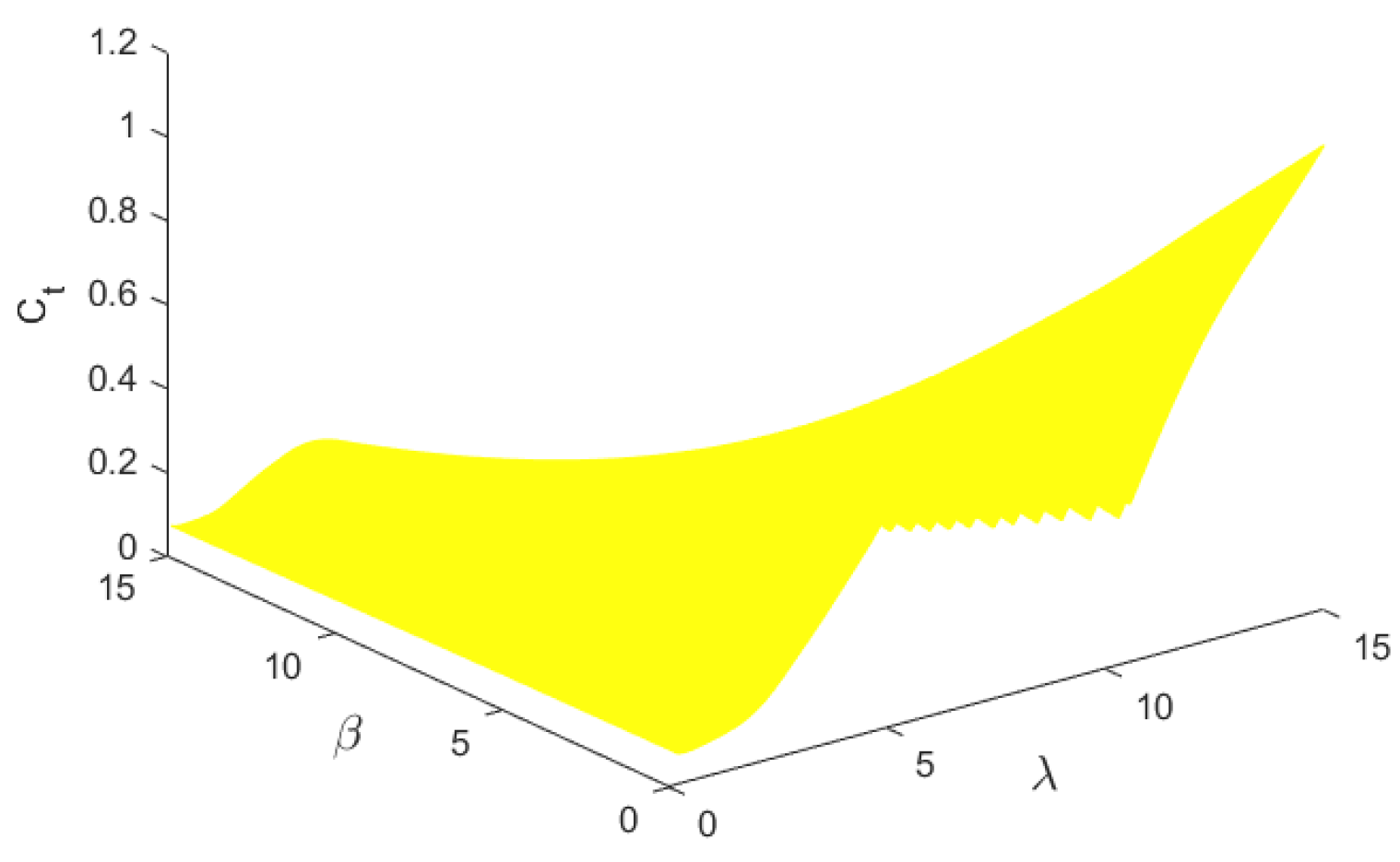
2.1. Wind Turbine Model

The wind energy captured by the wind turbine can be expressed as:
P m = 0.5 ρ π R 2 v 3 C p
T m = p m w r
where ρ is the air density; R is the length of wind turbine blade; v is the current wind speed; C p is the wind energy utilization coefficient, representing wind turbine’s ability to capture power from the wind energy; T m is the torque on the mechanical side; and w r is wind turbine rotor speed. According to Bates formula, the maximum utilization rate of wind energy cannot exceed 0.593, and the classical calculation formula is given in [30]:
C p = 0.5176 ( 116 1 λ 1 0.4 β 5 ) e 21 λ 1 + 0.0068 λ
1 λ 1 = 1 λ + 0.08 β 0.035 β 3 + 1
λ = w r R v
The wind turbine drive system consists of transmission parts and rotating parts. In order to better simulate the transmission shaft, this paper adopts the two-mass model as the transmission system [31]. The drive system model can be expressed as:
{ J m w ˙ r = T m T s T s = K s p ψ + K v i ψ ˙ J e w ˙ e = T s N g e a r T e
where ψ ˙ = w r w e N g e a r . In model (6), T e is the torque on the generator side, and T s is the torque on the intermediate shaft. Fluctuations in T s are considered to characterize the fatigue of the wind turbine drivetrain.
Considering that the electromagnetic transient process of generators is usually measured in milliseconds, the corresponding mathematical model is relatively simple and can be accurately described by the first-order inertial model. The output power can be expressed by:
{ T e + τ e T ˙ e = T e r e f P e = μ w e T e
where τ e is the inertia time of generator, T e r e f is the setpoint of generator torque, and μ is the generator efficiency.
The fatigue load of the wind turbine can be expressed by the mechanical torque T s and the tower bending moment M t [32], where the tower-bending moment can be expressed as:
{ M t = H F t F t = 0.5 ρ π R 2 v 2 C t
Here, H is tower height, F t is the thrust force, C t is thrust coefficient, and is related to pitch angle β and blade tip speed ratio λ, which can be obtained by looking up the lookup table shown in Figure 1.
Based on [33,34], it is generally considered that the fluctuation of the main shaft torque T s and the tower bending moment M t is used to calculate the fatigue load of the wind turbine. In order to better see the change of fatigue load in the operation of wind turbine, the block diagram of fatigue load calculation is shown in Figure 2, where B = ρ π R 2 v 2 .

2.2. Load-Reduction Control

Load-reduction control includes pitch angle control and rotor speed control, which is applicable in all wind speed conditions. It has the advantages of strong regulation ability and wide regulation range and is widely used in wind turbine models, but it is limited by mechanical characteristics: the wind turbine response speed becomes slow and frequent transformation will greatly reduce the operating life of the wind turbine. When operating at low wind speeds, the frequency modulation can only be completed by the rotor speed control. When running at high wind speed, a coordinated control strategy of rotor speed and pitch angle needs to be used for frequency modulation.
The control block diagram of common wind turbine pitch angle control is shown in Figure 3, where w m is the setpoint of the wind turbine speed, w r is the actual speed of generator, β r e f is the setpoint of the pitch angle, and β is the actual pitch angle.

3. Design and Optimization of LADRC

3.1. Active Disturbance Rejection Technology

Active disturbance rejection control does not need to know the specific and detailed model of the controlled plant and the external disturbances, so it can be assumed that the controlled plant is:
y ( n ) ( t ) = b 0 u ( t ) + f
where n and b 0 are the two parameters related to the controlled plant, representing the (relative) order and high-frequency gain of the controlled plant, respectively; f is the combination of unknown disturbance inside the system and external disturbance, called total disturbance.
The basic idea of active disturbance rejection control (ADRC) is to estimate the unknown total disturbances by using an extended state observer. Let
z 1 = y , z 2 = y ˙ , , z n = y ( n 1 ) , z n + 1 = f
If f is differentiable, let f ˙ = h , then (9) can be expressed as:
{ z ˙ = A e z + B e u + E e h y = C e z
where z = [ z 1 z 1 z n z n + 1 ] T ,
A e = [ 0 0 0 0 1 0 0 0 0 1 0 0 0 0 1 0 ] ( n + 1 ) × ( n + 1 )
B e = [ 0 0 b 0 0 ] ( n + 1 ) × 1 T ,
E e = [ 0 0 0 0 ] ( n + 1 ) × 1 T ,
C e = [ 1 0 0 0 ] 1 × ( n + 1 ) .
A full-order observer can be designed for the system:
{ z ^ ˙ = A e z ^ + B e u + L o ( y y ^ ) y ^ = C e z ^
where the observer gain $ L_o $ is
L o = [ β 1 β β n β n + 1 ] T
In the case that the total disturbance f is bounded, with A e L o C e asymptotically stable, z ^ 1 ( t ) , , z ^ n ( t ) will approach the output y ( t ) and its derivatives, and z ^ n + 1 ( t ) will approach f. This shows that the disturbance estimation can be used in control so that the disturbance can be suppressed faster.
Take the following control law:
u ( t ) = k 1 ( r ( t ) z ^ 1 ( t ) ) + + k n ( r ( n 1 ) ( t ) z ^ n ( t ) ) b 0 z ^ n + 1 ( t ) b 0 = K o ( r ^ ( t ) z ^ ( t ) )
where r ^ ( t ) is the generalized reference signal, which consists of the reference signal and its derivatives:
r ^ ( t ) = [ r ( t ) r ˙ ( t ) r ( n 1 ) ( t ) 0 ] T
The state feedback gain K o is defined as:
K o = [ k 1 k 2 k n 1 ] / b 0
The structure of LADRC is shown in Figure 4.
For first-order LADRC controller, the parameters that need to be adjusted are β 1 , β 2 , k 1 , b 0 . It has a simple structure, and with carefully chosen parameters, it can suppress all unknown disturbances f quickly.

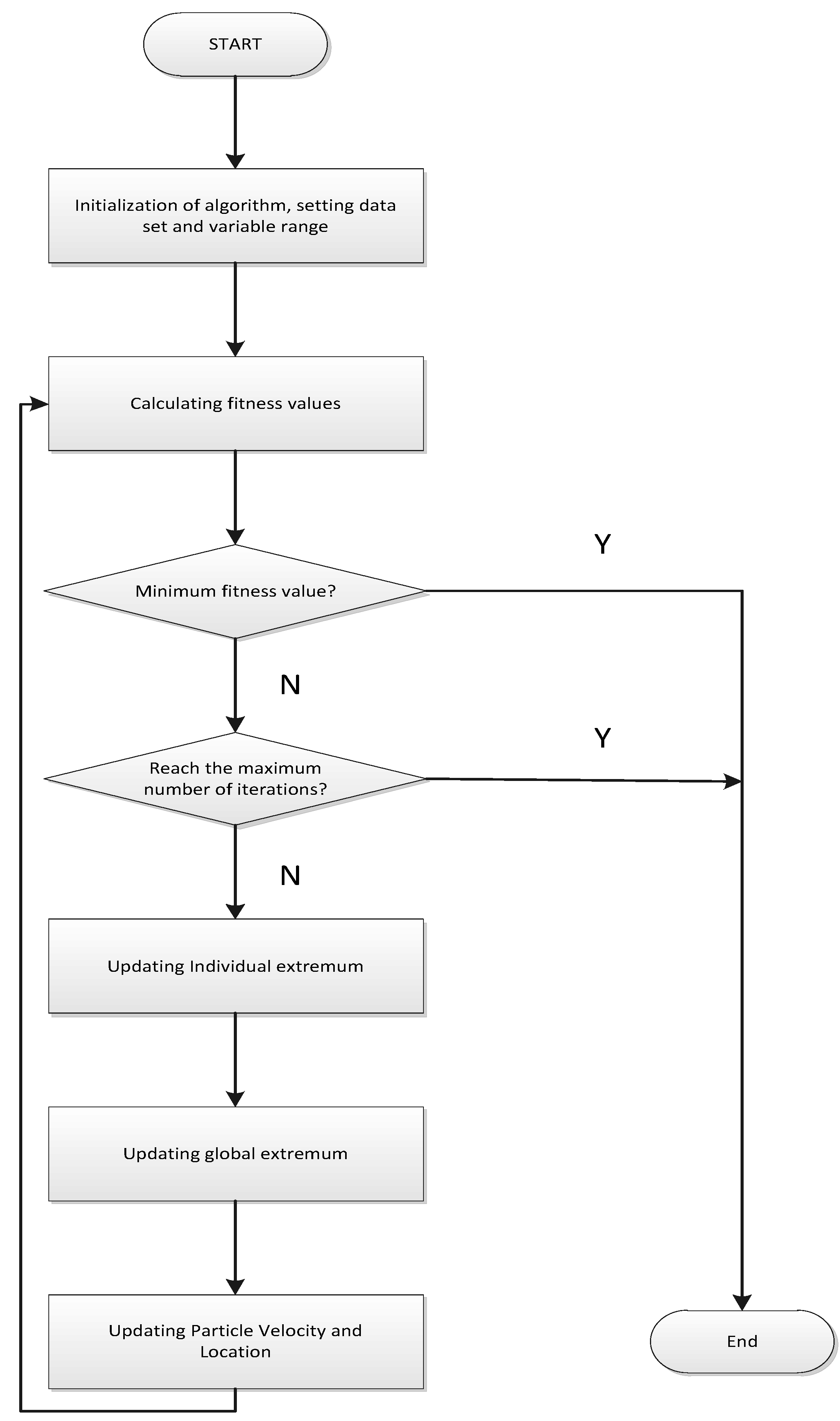
3.2. Optimization of Controller Parameters

This paper discusses the reduction in fatigue loads in wind turbines by using LADRC for pitch angle control. For comparison, PI controllers are also designed using the same index as LADRC. Considering the wind turbine power tracking, fatigue load, and uncertainty in the model, we use the PSO algorithm to optimize the controller performance.
The particle swarm optimization (PSO) technique was proposed by Kennedy and Eberhart [35] in 1995. PSO has several advantages; for instance, the algorithm is stochastic global optimization, parallel optimization, and the algorithm itself is simple and stable, with memory and evolution, and few parameters need to be adjusted. The algorithm is currently not only used in scientific retrieval but also suitable for practical engineering applications. PSO starts with a random solution and iterates to find the optimal solution. In addition, it can also evaluate the quality of the solution based on the fitness of the objective function.
Suppose a dimension space consists of a population of particles. The position of the i-th particle in the n-dimensional space is x i = [ x i 1 , x i 2 , , x i n ] T . The particle speed is v i = [ v i 1 , v i 2 , , v i n ] T , the optimal position of the individual particle is p i = [ p i 1 , p i 2 , , p i n ] T , and the globally optimal position in the entire particle swarm is p g = [ p g 1 , p g 2 , p g n ] T . In the process of algorithm iteration, the velocity and position of particles can be described as:
{ V i d k + 1 = w V i d k + c 1 r 1 ( P i d k X i d k ) + c 2 r 2 ( P g d k X i d k ) X i d k + 1 = X i d k + V i d k + 1
w is the inertial weight; d = 1 , 2 , ; k is the number of algorithm iterations; c 1 and c 2 are the acceleration factors; and both r 1 and r 2 are random numbers ranging [ 0 , 1 ] .
The particle velocity update represented by Equation (17) is divided into three parts: the first part is the speed of the particle at the previous moment; the second part is the distance between the current position of the particle and the current optimal position of the particle; the last part is the distance between the current position of the particle and the globally optimal position of the particle. The algorithm flow is as follows:
  • Initialize the random position and velocity of each particle in the particle swarm within the specified interval.
  • Calculate the fitness function of each particle to determine this globally optimal solution.
  • Update the position and velocity of the particle according to the current globally optimal solution and the historical globally optimal solution.
  • Determine whether the set maximum number of iterations is reached and whether the minimum limit is met. If satisfied, end the iteration; otherwise, repeat steps 2–4.
The block diagram of the PSO optimization algorithm for wind turbine fatigue load is shown in Figure 5.
The involvement of wind turbines in frequency modulation will cause frequent changes in the pitch angle, which increases the fatigue load of the WT. The fatigue load is related to the fluctuations of T s and M t . It can simply be considered that the smaller their fluctuations, the smaller the fatigue loads. That is to say, the smaller the integral of Δ T s 2 and Δ M t 2 , the smaller the fatigue load. Therefore, the objective function of fatigue load and power output can usually be simply described as:
F a t i g u e   L o a d = Δ T s 2 + α   Δ M t 2
C F = ( α 1 (   Δ T s 2 + α   Δ M t 2 ) + ( 1 α 1 )   Δ P o u t 2 ) d t
where α is the weight of the two main fatigue loads ( α = 0.01 in this paper); α 1 is the weight of the objective function, which determines the trade-off of the fatigue load and the power tracking ( α 1 = 0.4 in the paper).
In order to further reduce the fatigue load of the wind turbine, considering the limitation of the fluctuation of T s and M t , the total variation is introduced to the objective function. The total variational is expressed as:
V T = ( α 2 | T s n + 1 T s n | + | M t n + 1 M t n | )
where α 2 is the coefficient of variation of T s and M t . In the study, α 2 = 5 . So, the new objective function can be expressed as:
min C = C F + α 3 V T
where α 3 is the coefficient of the objective function.

4. Simulation Results and Discussions

The wind turbine used in the simulation part of this paper is designed with reference to the full-scale wind turbine model (NREL 5 MW) in the SimWindFarm toolbox. This toolbox was developed by Aalborg University and is capable of simulating the grid-connected operation of wind turbines [36]. The specific parameters of the wind turbine are shown in Table 1.

4.1. Controller Parameters

During parameter optimization, the wind speeds are characteristic wind speeds generated by SimWindFarm [37]. The wind speed was set to 15 m/s average wind speed, 0.1 turbulence intensity, and the wind speed curve of 10 min, as shown in Figure 6. Moreover, wind turbines generate electricity at maximum power. For better control performance, the PSO algorithm adopts the objective function of different parameters α 3 to optimize the controller, where the value of α 3 ranges from 0 to 2000. Considering the randomness of the results of the PSO algorithm, after each change of the objective function, the controller parameters are optimized five times, and the optimal parameters of the controller are obtained by minimizing the objective function. To prove that the obtained controller parameters are optimal, the convergence curve of the PSO algorithm is shown in Figure 7. The optimized results of different parameters are shown in Table 2; as α 3 increases, the cost function decreases. In addition, when α 3 reaches 1500, C F decreases by 16.5% and remains largely unchanged in the future because it is found that the fluctuation of the rotor speed increases. Therefore, this paper adopts the objective function when the parameter is α 3 = 1500 for optimization analysis. The final optimized controller parameters are shown in Table 3.

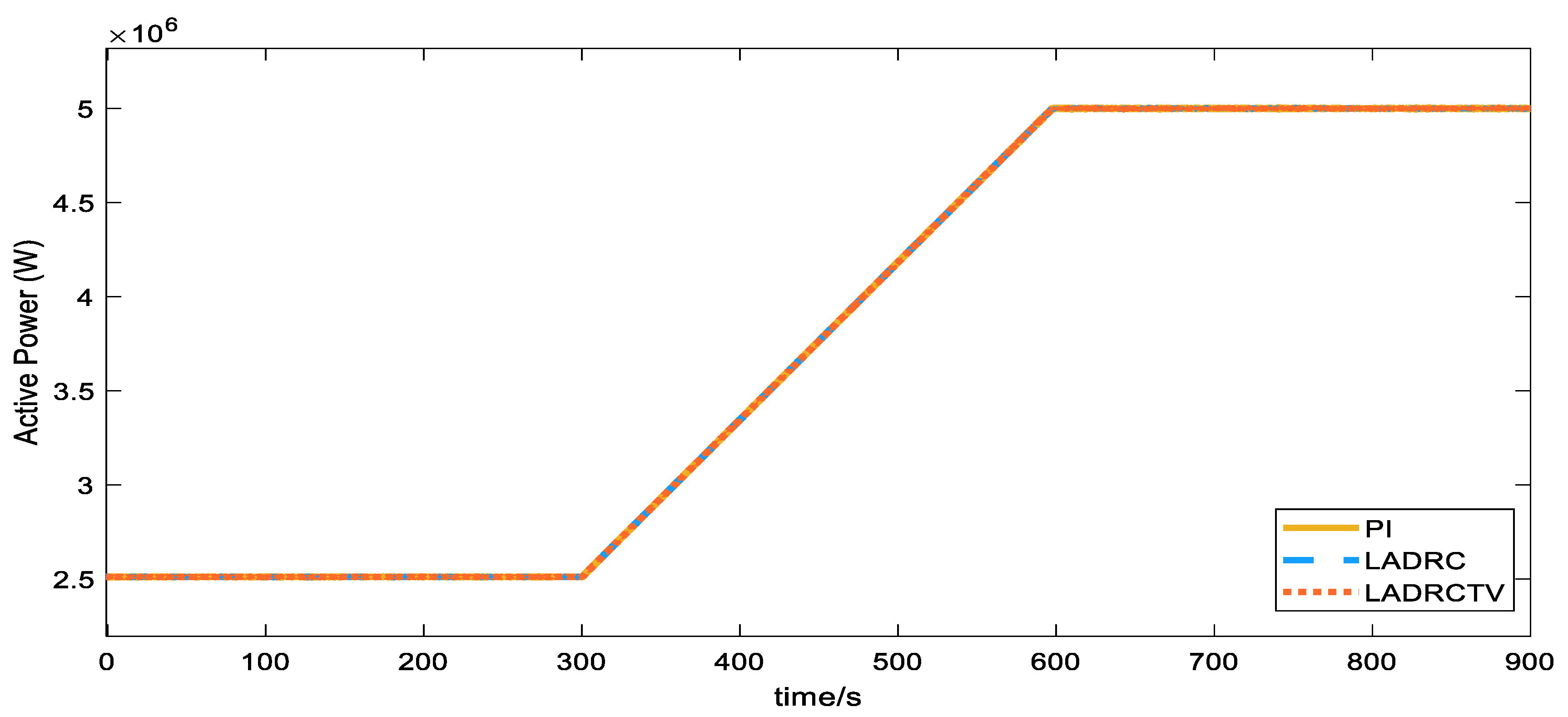
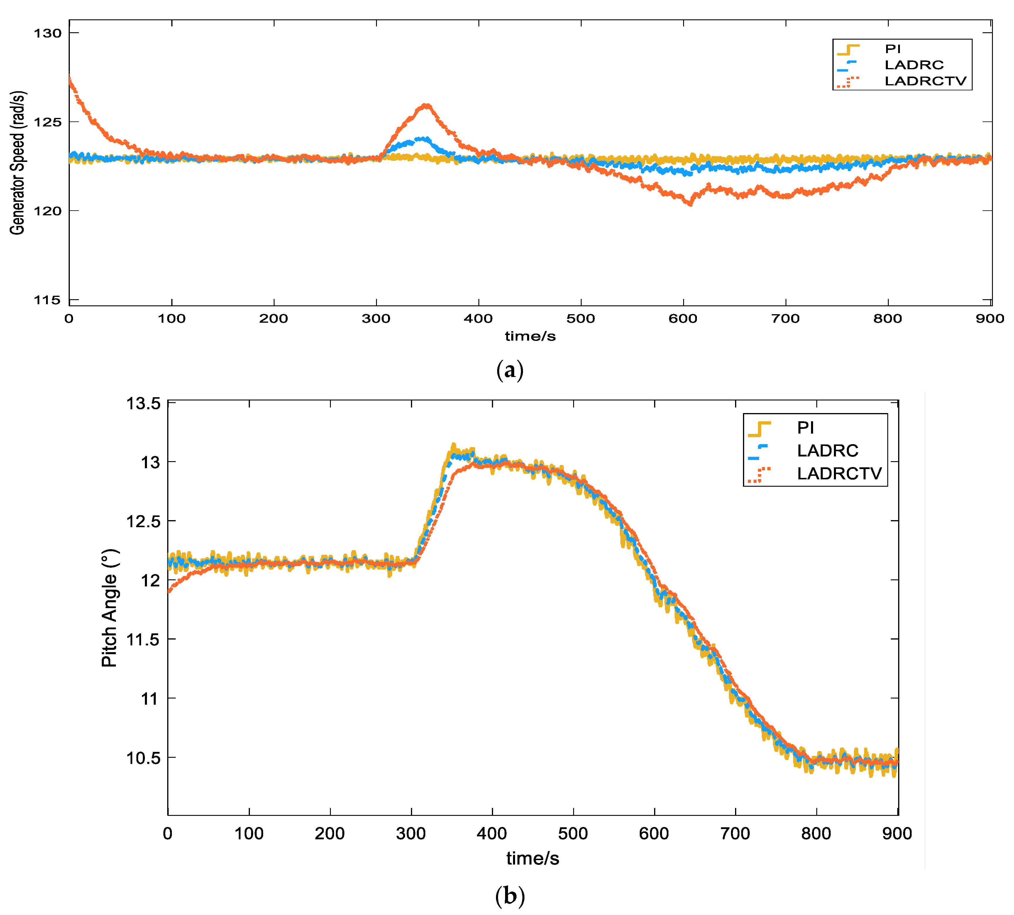
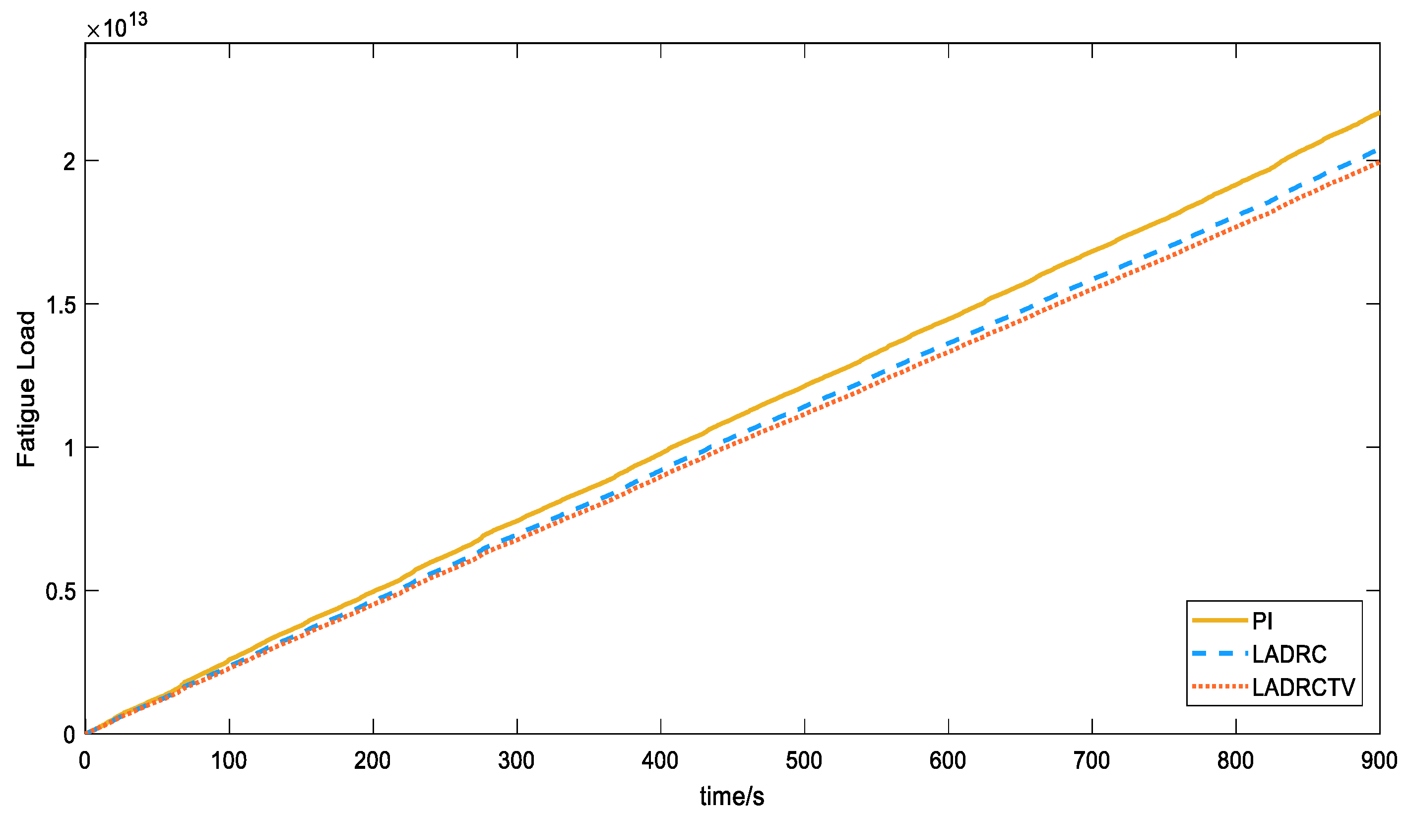
4.2. Analysis Results and Discussion

In order to further verify the effectiveness of the optimized controller, tests are carried out under different operating conditions of the wind turbine. The simulation time of this case is 900 s. In order to prove the superiority of the controller, the experimental part adopts a complex wind speed model, including a basic wind speed of 14 m/s, a gust with an amplitude of 1, a step wind with an amplitude of 1, and a random wind with an amplitude of 2. As shown in Figure 8, a 300 s simulation is carried out for the three common modes in wind turbine operation: delta mode, rate constraint mode, and absolute production constraint mode. The active power results of wind turbines under three different control strategies—proportional–integral controller (PI), Linear Active Disturbance Rejection Controller (LADRC), and Linear Active Disturbance Rejection Controller with Total Variation Optimization (LADRCTV)—are shown in Figure 9.
In Figure 9, the delta mode is used from 0 to 300 s, at which time the wind turbine limits the power to 50% of the maximum output power. From 300 to 600 s, the rate constraint method is adopted, and the power increases slowly with a slope of 0.5 MW/min. During the 600~900 s period, the absolute production limit mode is adopted; at this time, the wind turbine is allowed to operate with a maximum output power of 5 MW. The simulation results show that in the face of complex wind speed conditions, the three control strategies can realize the active power-tracking control of the above modes.
As shown in Figure 10, under more complex wind speed conditions, after adopting the LADRC control strategy, the rotor speed fluctuation range of the wind turbine is wide, there is a small range of fluctuations, and the pitch angle fluctuation is significantly reduced. On this basis, the LADRC control effect after adding total variable optimization is more obvious, and the pitch angle fluctuation is smaller, which effectively reduces the frequent large-scale fluctuation of the wind turbine pitch angle. Therefore, the simulation results of the shaft torque and tower bending moment in Figure 11 show that the designed LADRC controller has a more obvious suppression effect on the fluctuation of these two parameters. In the case of large-scale fluctuations in wind speed, the shaft torque fluctuates slightly, but after reaching a steady state, it has a good tracking performance, as shown in Figure 11a. As for the tower-bending moment, as shown in Figure 11b, the LADRC controller considering the total variation has less fluctuation in the tower-bending moment under various working conditions, which effectively reduces the tower-bending moment. Finally, as shown in Figure 12, the two main factors affecting the fatigue load of the wind turbine are comprehensively considered. During the continuous operation of the wind turbine, the fatigue load of the wind turbine increases with time, and the fatigue load of the wind turbine using the LADRC controller increases slowly. The overall fatigue load of the wind turbine with the LADRC controller is reduced by 6%, and the final fatigue load of the LADRC controller with the total variation is also smaller than the other controllers, which is 3% lower than that of the LADRC controller. This shows that the LADRC controller designed under complex wind speed conditions has a good control effect on tracking the output power of the wind turbine and reducing the fatigue load of the wind turbine.
In the selection of α 3 , it should be noted that with the continuous increase in its value, the fluctuation degree of the shaft torque will increase, which will increase the fatigue load of the wind turbine in a disguised form. Therefore, when facing different objects, it is necessary to further adjust the selection of α 3 to achieve the optimal effect.

5. Conclusions

Aiming at the active power control of wind turbines, this paper proposes a linear active disturbance rejection control and its optimization method considering the total variation of wind turbine shaft torque and tower-bending moment to reduce fatigue load. By designing a linear active disturbance rejection controller, the wind turbine can achieve power reference tracking while reducing the influence of the wind turbine fatigue load. A PSO algorithm considering the fatigue load and the total variation of the wind turbine shaft torque and tower-bending moment is established, which can improve the control effect. For the weight parameter selection problem in the objective function, under the same conditions, the optimal weight of the objective function is obtained through multiple simulation optimizations. The controller parameters optimized multiple times further improve the optimization effect. When is 1500, the wind turbine’s C F were reduced by 16.8%. A case study under complex wind speed conditions shows that the proposed control and optimization method can significantly reduce the pitch angle fluctuation and reduce the fatigue load of the wind turbine. Additionally, the fatigue load of the LADRC controller is reduced by 6%, and LADRCTV is a further 3% lower than that while achieving excellent power tracking performance. The proposed control strategy and optimization method can be applied to reduce the fatigue load of wind turbines with frequent fluctuations. The increase in will increase the shaft torque of the wind turbine to a certain extent. Therefore, when facing different objects, it is necessary to further discuss the value to ensure the best control performance.

Author Contributions

Conceptualization, X.J.; methodology, X.J.; software, X.J.; validation, X.J., Y.Z. and Z.W.; formal analysis, X.J.; investigation, Y.Z.; resources, W.T.; data curation, Y.Z.; writing—original draft preparation, X.J.; writing—review and editing, Y.Z. and W.T.; visualization, Y.Z., X.J. and Z.W.; supervision, W.T.; project administration, W.T.; funding acquisition, W.T. All authors have read and agreed to the published version of the manuscript.

Funding

This research received no external funding.

Institutional Review Board Statement

Not applicable.

Informed Consent Statement

Not applicable.

Data Availability Statement

Data are contained within the article.

Conflicts of Interest

The authors declare no conflict of interest.

References

  1. Datta, U.; Shi, J.; Kalam, A. Primary frequency control of a microgrid with integrated dynamic sectional droop and fuzzy based pitch angle control. Int. J. Electr. Power Energy Syst. 2019, 111, 248–259. [Google Scholar] [CrossRef]
  2. Prasad, S.; Purwar, S.; Kishor, N. Non-linear sliding mode control for frequency regulation with variable-speed wind turbine systems. Int. J. Electr. Power Energy Syst. Accept. 2019, 107, 19–33. [Google Scholar] [CrossRef]
  3. Baccino, F.; Conte, F.; Grillo, S.; Massucco, S.; Silvestro, F. An optimal model-based control technique to improve wind farm participation to frequency regulation. In Proceedings of the 2015 IEEE Power & Energy Society General Meeting, Denver, CO, USA, 26–30 July 2015; pp. 993–1003. [Google Scholar] [CrossRef]
  4. Haces-Fernandez, F.; Li, H.; Ramirez, D. Improving wind farm power output through deactivating selected wind turbines. Energy Convers. Manag. 2020, 187, 407–422. [Google Scholar] [CrossRef]
  5. Liu, Y.; Wang, Y.; Wang, X.; Zhu, J.; Lio, W.H. Active Power Dispatch for Supporting Grid Frequency Regulation in Wind Farms Considering Fatigue Load. Energies 2019, 12, 1508. [Google Scholar] [CrossRef]
  6. Camblong, H.; Nourdine, S.; Vechiu, I.; Tapia, G. Control of wind turbines for fatigue loads reduction and contribution to the grid primary frequency regulation. Energy 2012, 48, 284–291. [Google Scholar] [CrossRef]
  7. Liu, Y.; Gracia, J.R.; King, T.J.; Liu, Y. Frequency Regulation and Oscillation Damping Contributions of Variable-Speed Wind Generators in the U.S. Eastern Interconnection (EI). IEEE Trans. Sustain. Energy 2017, 6, 951–958. [Google Scholar] [CrossRef]
  8. Wang, R.; Xie, Y.; Zhang, H.; Li, C.; Li, W.; Terzija, V. Dynamic Power Flow Algorithm Considering Frequency Regulation of Wind Power Generators. Iet Renew. Power Gener. 2017, 11, 1218–1225. [Google Scholar] [CrossRef]
  9. Xu, Z.; Zha, X.; Yue, S.; Chen, Y. A Frequency Regulation Strategy for Wind Power Based on Limited Over-Speed De-Loading Curve Partitioning. IEEE Access 2018, 6, 22938–22951. [Google Scholar]
  10. Morren, J.; de Haan, S.W.H.; Kling, W.L.; Ferreira, J.A. Wind Turbines Emulating Inertia and Supporting Primary Frequency Control. IEEE Trans. Power Syst. 2006, 21, 433–434. [Google Scholar] [CrossRef]
  11. Qin, S.; Chang, Y.; Xie, Z.; Li, S. Improved Virtual Inertia of PMSG-Based Wind Turbines Based on Multi-Objective Model-Predictive Control. Energies 2021, 14, 3612. [Google Scholar] [CrossRef]
  12. Ekanayake, J.; Jenkins, N. Comparison of the response of doubly fed and fixed-speed induction generator wind turbines to changes in network frequency. IEEE Trans. Energy Convers. 2004, 19, 800–802. [Google Scholar] [CrossRef]
  13. Gonzalez-Longatt, F.; Chikuni, E.; Rashayi, E. Effects of the Synthetic Inertia from wind power on the total system inertia after a frequency disturbance. In Proceedings of the 2013 IEEE International Conference on Industrial Technology (ICIT), Cape Town, South Africa, 25–28 February 2013; pp. 826–832. [Google Scholar]
  14. Huang, L.; Xin, H.; Zhang, L.; Wang, Z.; Wu, K.; Wang, H. Synchronization and Frequency Regulation of DFIG-Based Wind Turbine Generators With Synchronized Control. IEEE Trans. Energy Convers. 2017, 32, 1251–1262. [Google Scholar] [CrossRef]
  15. Bashetty, S.; Guillamon, J.I.; Mutnuri, S.S.; Ozcelik, S. Design of a Robust Adaptive Controller for the Pitch and Torque Control of Wind Turbines. Energies 2020, 13, 1195. [Google Scholar] [CrossRef]
  16. Pathak, D.; Gaur, P. A fractional order fuzzy-proportional-integral-derivative based pitch angle controller for a direct-drive wind energy system. Comput. Electr. Eng. 2019, 78, 420–436. [Google Scholar] [CrossRef]
  17. Xu, B.; Yuan, Y.; Liu, H.; Jiang, P.; Gao, Z.; Shen, X.; Cai, X. A Pitch Angle Controller Based on Novel Fuzzy-PI Control for Wind Turbine Load Reduction. Energies 2020, 13, 6086. [Google Scholar] [CrossRef]
  18. Leith, D.J.; Leithead, W.E. Appropriate realization of gain-scheduled controllers with application to turbine regulation. Int. J. Control 1996, 65, 223–248. [Google Scholar] [CrossRef]
  19. Stol, K.; Rigney, B.; Balas, M. Disturbance Accommodating Control of a variable-speed turbine using a symbolic dynamics structural model. In Proceedings of the ASME Wind Energy Symposium, Reno, NV, USA, 10–13 January 2000. [Google Scholar]
  20. Balas, M.J.; Yuan, Y.; Liu, H.; Jiang, P.; Gao, Z.; Shen, X.; Cai, X. Dynamics and control of horizontal axis wind turbines. In Proceedings of the 2003 American Control Conference, Denver, CO, USA, 4–6 June 2003; IEEE: New York, NY, USA, 2003. [Google Scholar]
  21. Cao, Z.; Wang, X.; Jin, T. Control strategy of large-scale DFIG-based wind farm for power grid frequency regulation. In Proceedings of the 31st Chinese Control Conference IEEE, Hefei, China, 25–27 July 2012. [Google Scholar]
  22. Tielens, P.; de Rijcke, S.; Srivastava, K.; Reza, M.; Marinopoulos, A.; Driesen, J. Frequency Support by Wind Power Plants in Isolated Grids with Varying Generation Mix. In Proceedings of the Power & Energy Society General Meeting IEEE, San Diego, CA, USA, 22–26 July 2012. [Google Scholar]
  23. Yao, Q.; Liu, J.; Hu, Y. Optimized Active Power Dispatching Strategy Considering Fatigue Load of Wind Turbines During De-Loading Operation. IEEE Access 2019, 7, 17439–17449. [Google Scholar] [CrossRef]
  24. Mancinial, S.; Sarzo, F.; Ferrari-Trecate, G. Model Predictive Controllers for Reduction of Mechanical Fatigue in Wind Farms. IEEE Trans. Control. Syst. Technol. 2016, 25, 535–549. [Google Scholar]
  25. Torben, K.; Thomas, B.; Mikael, S. Survey of wind farm control-power and fatigue optimization. Wind Energy 2014, 18, 1333–1351. [Google Scholar]
  26. Buhl, M.L. MCrunch User’s Guide for Version 1.00. 2008; p. 16. Available online: https://www.nrel.gov/wind/nwtc/mcrunch.html (accessed on 15 March 2022).
  27. Han, J. Auto-disturbances-rejection Controller and Its Applications. Control. Decis. 1998, 13, 19–23. [Google Scholar]
  28. Liu, Y.; Liu, J.; Zhou, S. Linear active disturbance rejection control for pressurized water reactor power. Ann. Nucl. Energy 2018, 111, 22–30. [Google Scholar] [CrossRef]
  29. Jonkman, J.M.; Butterfield, S.; Musial, W.; Scott, G. Definition of a 5-MW Reference Wind Turbine for Offshore System Development; National Renewable Energy Lab: Lakewood, CO, USA, 2009. [Google Scholar]
  30. Heier, S. Grid Integration of Wind Energy Conversion Systems; John Wiley&Sons Inc.: Hoboken, NJ, USA, 2006; Available online: https://book.douban.com/subject/2853278/ (accessed on 11 September 2019).
  31. Iov, F. Wind Turbine Blockset in Matlab Simulink; Aalborg University: Aalborg, Denmark, 2004. [Google Scholar]
  32. Spudic, V. Coordinated Optimal Control of Wind Farm Active Power; University of Zagreb: Agram, Croatia, 2012. [Google Scholar]
  33. Zhang, J.; Liu, Y.; Tian, D.; Yan, J. Optimal power dispatch in wind farm based on reduced blade damage and generator losses. Renew. Sustain. Energy Rev. 2015, 44, 64–77. [Google Scholar] [CrossRef]
  34. Biegel, B.; Madjidian, D.; Spudic, V.; Rantzer, A.; Stoustrup, J. Distributed low-complexity controller for wind power plant in derated operation. In Proceedings of the 2013 IEEE International Conference on Control Applications (CCA), Hyderabad, India, 28–30 August 2013; pp. 146–151. [Google Scholar] [CrossRef] [Green Version]
  35. Poli, R.; Kennedy, J.; Blackwell, T. Particle swarm optimization. Swarm Intell 2007, 1, 33–57. [Google Scholar] [CrossRef]
  36. Aalborg University. SimWindFarm Toolbox, n.d. Available online: https://www.ict-aeolus.eu/SimWindFarm/index.html (accessed on 7 March 2022).
  37. Grunnet, J.D.; Soltani, M.; Knudsen, T.; Kragelund, M.N.; Bak, T. Aeolus Toolbox for Dynamics Wind Farm Model, Simulation and Control. In Proceedings of the European Wind Energy Conference&Exhibition, Warsaw, Poland, 2–4 April 2010. [Google Scholar]
Figure 1. C t based on lookup table.
Energies 15 06178 g001
Figure 2. Block diagram of fatigue load.
Energies 15 06178 g002
Figure 3. Block diagram of pitch angle control.
Energies 15 06178 g003
Figure 4. Linear active disturbance rejection controller.
Energies 15 06178 g004
Figure 5. Process for optimizing wind turbine fatigue loads through particle swarm optimization.
Energies 15 06178 g005
Figure 6. Wind speed curve for optimization.
Energies 15 06178 g006
Figure 7. Convergence curve of PSO algorithm when α 3 = 1500 .
Energies 15 06178 g007
Figure 8. The curve of wind speed.
Energies 15 06178 g008
Figure 9. Wind turbine running curve in different modes.
Energies 15 06178 g009
Figure 10. (a) Variations of generator speed; (b) Variations of pitch angle.
Energies 15 06178 g010
Figure 11. (a) Fluctuation of main shaft torque; (b) Fluctuation of tower-bending moment.
Energies 15 06178 g011aEnergies 15 06178 g011b
Figure 12. Fatigue load of wind turbine.
Energies 15 06178 g012
Table 1. Parameters for WT.
ParameterNameValue
ρAir density63 m
RRadius of blade1.22 kg/m3
J m Rotor inertia3.5 × 107 kg · m2
J e Generator inertia5.3 × 102 kg · m2
HTower height87.6 m2
η g Gearbox ratio97
τ e Time inertia of generator0.1
P max Rated power5 MW
Table 2. The cost function when α 3 changes.
α 3 C F Percentage/%
01.3534 × 10120
5001.2866 × 1012−4.94
10001.2204 × 1012−9.83
15001.1303 × 1012−16.5
20001.1078 × 1012−18.2
Table 3. The optimal PI parameters and LADRC parameters for α 3 = 0 , α 3 = 1500 .
Controller K p K I k 1 b 0 β 1 β 2
PI−0.2143−0.0918
LADRC for α 3 = 0 −47.81179.755187.73333.37
LADRC for α 3 = 1500 −18.81261.75823.17139.84
Publisher’s Note: MDPI stays neutral with regard to jurisdictional claims in published maps and institutional affiliations.

