
Comparative Analysis of the Failure Rates of Shearer and Plow Systems—A Case Study


Abstract
:1. Introduction
2. Materials and Methods
- number of days—this value specifies the total number of days during which the system was in operation, [-];
- daily net output—an average coal weight per day, [Mg/d];
- gross output—this value determines the total mass of excavated material, [Mg];
- daily gross output—an average weight of excavated material per day, [Mg/d];
- waste rock output—this value determines the total mass of excavated rock, [Mg];
- daily waste rock output—an average mass of excavated waste rock per day, [Mg/d];
- share of waste rock—wt% of waste rock in gross excavated material, [%].
- the average failure duration was 100.73 min;
- there are an average of 1.74 failures per day;
- the average failure duration per 1000 Mg of gross spoil is 18.94 min;
- the average failure duration per 1000 Mg of net spoil is 26.59 min;
- the average failure duration per 1000 Mg of waste rock is 65.83 min;
- there are an average of 0.19 failures per 1 thous. Mg of gross spoil;
- there are an average of 0.26 failures per 1 thous. Mg of spoil net;
- there are an average of 0.65 failures per 1 thous. Mg of waste rock ore.
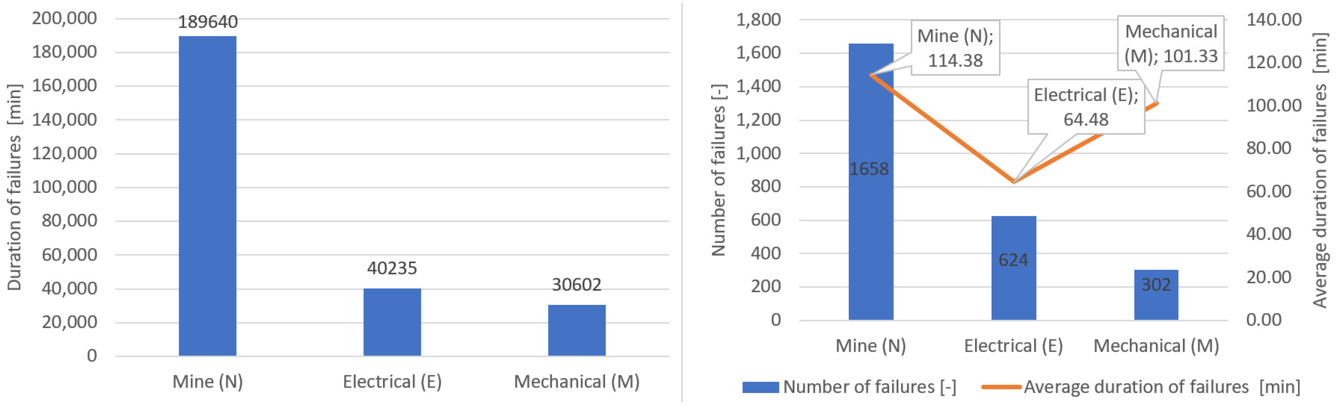
- mining failures—time 189,640 min, the number of failures—1658, average duration of failure—114 min;
- electrical failures—time 40,235 min, the number of failures—624, average duration of failure—64 min;
- mechanical failures—time 30,602 min, the number of failures—302, average duration of failure—101 min.
3. LW Bogdanka S.A. Hard Coal Mine
- overburden with a thickness of ca 700 m;
- almost horizontal deposition of coal and waste rock layers;
- relatively weak rocks accompanying hard coal seams;
- absence of major faults;
- water-filled layers characterised by a high water pressure and a layer of quicksand.
4. Failure Rate by Failure Category
- total number of failures;
- failure time in total;
- number of failures per one day;
- failure time per one day;
- number of failures per 1000 Mg of excavated material;
- failure time per 1000 Mg of excavated material.
5. Analysis of Shearer Longwall Failure Rate
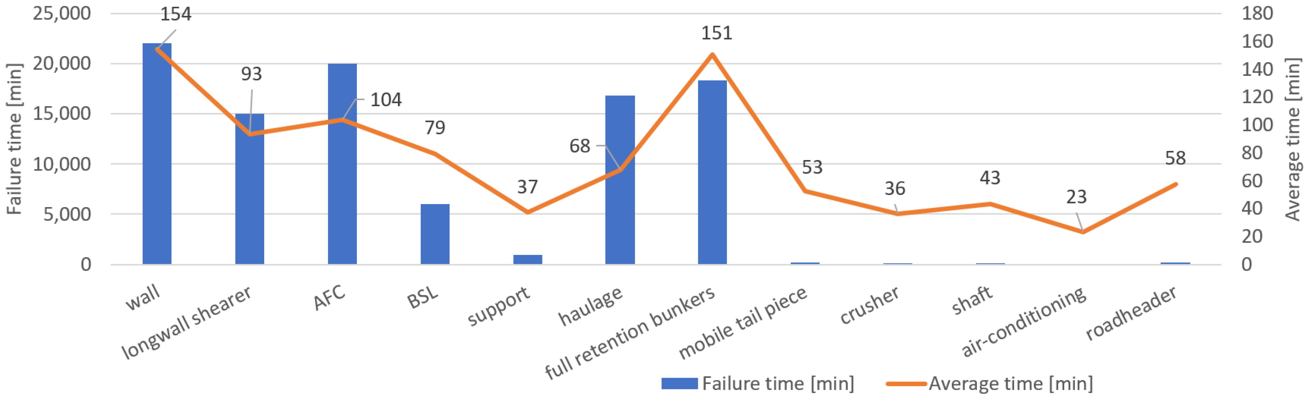
- The failures were most frequently related to haulage, face conveyor, longwall shearer, longwall downtime and full-retention bunkers, accounting for more than 85% of the total number of failures;
- The longest-lasting failures were those related to longwall downtime, face conveyor, full-retention bunkers, haulage and longwall shearer, successively, accounting for more than 90% of all failure duration.
- Among the major failures, on average, the longest-lasting were those related to longwall downtime (154 min), full-retention bunkers (151 min), face conveyor (104 min), longwall shearer (93 min) and haulage (68 min).
- Failures related to longwall shearer accounted for 16% of the number of failures and 5% of failure time.
6. Analysis of Plow Longwall Failure Rate
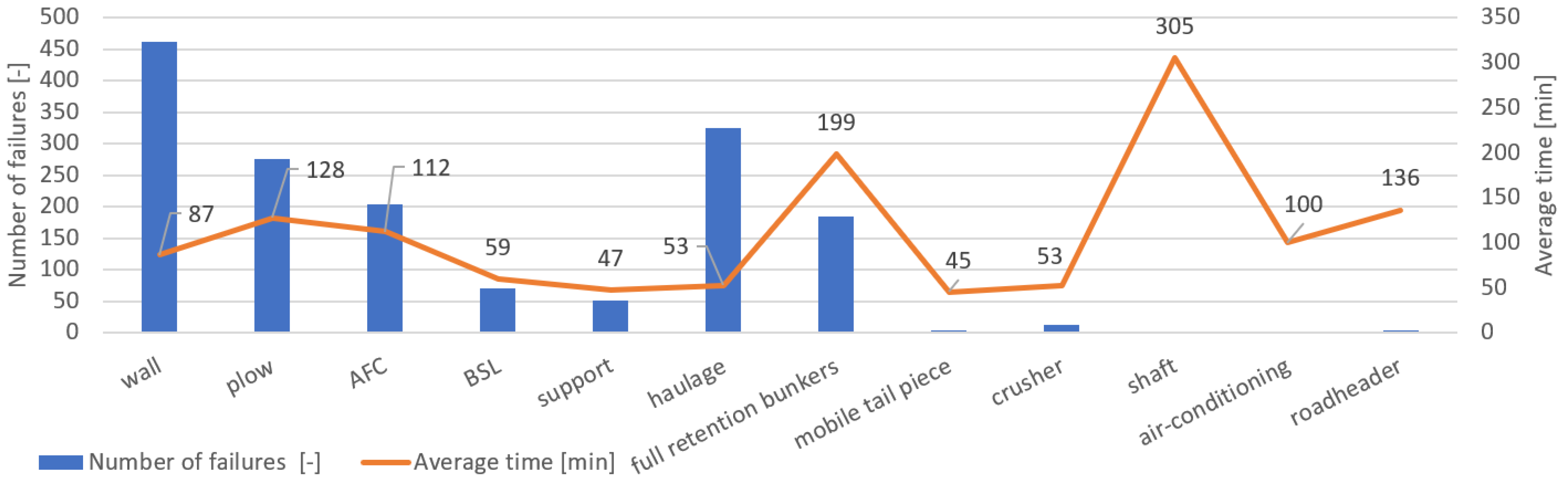
- The failures are most frequently related to longwall downtime, haulage, plow, face conveyor and full-retention bunkers, accounting for more than 90% of all failures;
- The longest-lasting failures were those related to face downtime, full-retention bunkers, plow, longwall conveyor and haulage, accounting for nearly 95% of all failure duration;
- Among the major failures, on average, the longest-lasting were those related to full retention bunkers (199 min), plow (128 min), face conveyor (112 min), longwall downtime (87 min) and haulage (53 min);
- Plow failures account for 17% of failures and 22% of failure time.
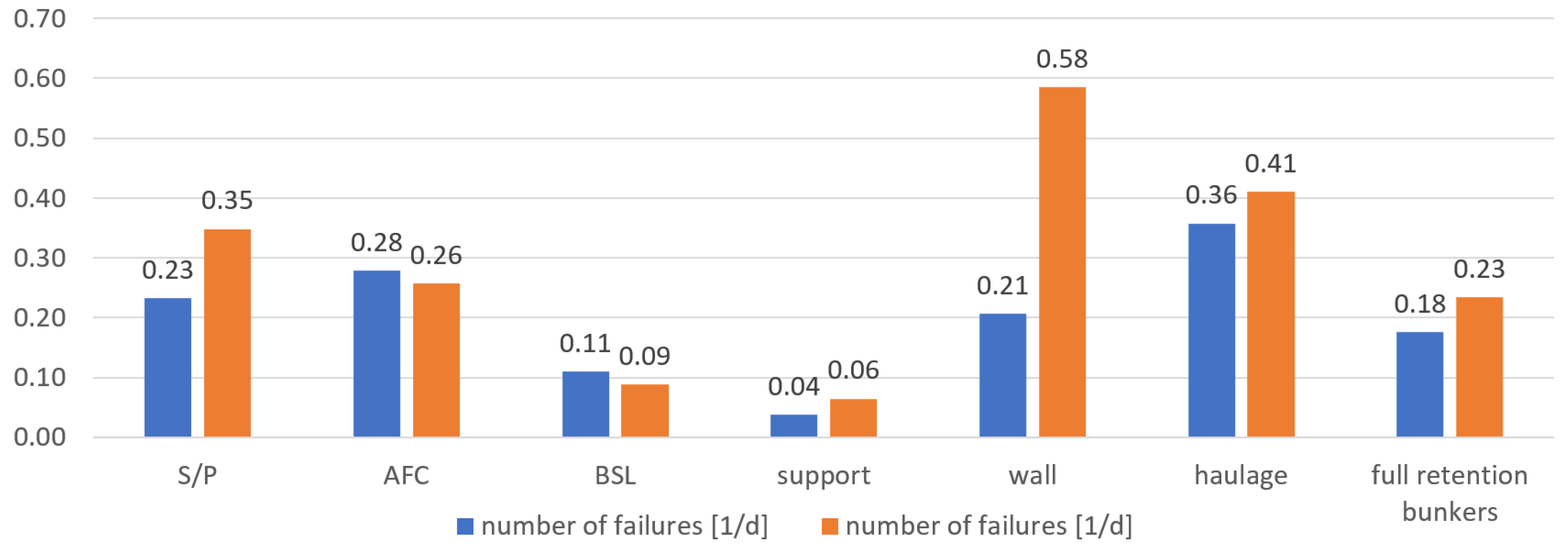
7. Results of Comparison of the Systems Failure Rates
- mining machine: S/P (shearer/plow);
- armoured face conveyor: AFC;
- beam stage loader: BSL;
- support: support;
- longwall downtime: longwall;
- haulage: haulage;
- full-retention bunkers: full-retention bunkers.
8. Conclusions
Author Contributions
Funding
Institutional Review Board Statement
Informed Consent Statement
Data Availability Statement
Acknowledgments
Conflicts of Interest
References
- Bołoz, Ł. Longwall shearers for exploiting thin coal seams as well as thin and highly inclined coal seams. Min. Inform. Autom. Electr. Eng. 2018, 4, 59. [Google Scholar] [CrossRef]
- Bołoz, Ł. Unique project of single-cutting head longwall shearer used for thin coal seams exploitation. Arch. Min. Sci. 2013, 58, 1057–1070. [Google Scholar]
- Bołoz, Ł. Model tests of longwall shearer with string feed system. Arch. Min. Sci. 2018, 63, 61–74. [Google Scholar]
- Bołoz, Ł.; Castañeda, L. Computer-aided support for the rapid creation of parametric models of milling units for longwall shearers. Manag. Syst. Prod. Eng. 2018, 26, 193–199. [Google Scholar] [CrossRef]
- Bołoz, Ł. Interpretation of the results of mechanical rock properties testing with respect to mining methods. Acta Montan. Slovaca 2020, 25, 81–93. [Google Scholar]
- Kotwica, K.; Małkowski, P. Methods of Mechanical Mining of Compact-Rock—A Comparison of Efficiency and Energy Consumption. Energies 2019, 12, 3562. [Google Scholar] [CrossRef]
- Bołoz, Ł.; Biały, W. Automation and Robotization of Underground Mining in Poland. Appl. Sci. 2020, 10, 7221. [Google Scholar] [CrossRef]
- Kozłowski, A.; Bołoz, Ł. Design and Research on Power Systems and Algorithms for Controlling Electric Underground Mining Machines Powered by Batteries. Energies 2021, 14, 4060. [Google Scholar] [CrossRef]
- Bołoz, Ł.; Kozłowski, A. Methodology for Assessing the Stability of Drilling Rigs Based on Analytical Tests. Energies 2021, 14, 8588. [Google Scholar] [CrossRef]
- Hrinov, V.; Khorolskyi, A. Improving the process of coal extraction based on the parameter optimization of mining equipment. E3S Web Conf. 2018, 60, 17. [Google Scholar] [CrossRef]
- Jedliński, Ł.; Syta, A.; Gajewski, J.; Jonak, J. Nonlinear analysis of cylindrical gear dynamics under varying tooth breakage. Measurement 2022, 190, 110721. [Google Scholar] [CrossRef]
- Kotwica, K.; Stopka, G.; Kalita, M.; Bałaga, D.; Siegmund, M. Impact of Geometry of Toothed Segments of the Innovative KOMTRACK Longwall Shearer Haulage System on Load and Slip during the Travel of a Track Wheel. Energies 2021, 14, 2720. [Google Scholar] [CrossRef]
- Małkowski, P.; Ostrowski, Ł.; Stasica, J. Modeling of Floor Heave in Underground Roadways in Dry and Waterlogged Conditions. Energies 2022, 15, 4340. [Google Scholar] [CrossRef]
- Rak, Z.; Stasica, J.; Burtan, Z.; Chlebowski, D. Technical Aspects of Mining Rate Improvement in Steeply Inclined Coal Seams: A Case Study. Resources 2020, 9, 138. [Google Scholar] [CrossRef]
- Szurgacz, D.; Trzop, K.; Gil, J.; Zhironkin, S.; Pokorný, J.; Gondek, H. Numerical Study for Determining the Strength Limits of a Powered Longwall Support. Processes 2022, 10, 527. [Google Scholar] [CrossRef]
- Biały, W. Application of quality management tools for evaluating the failure frequency of cutter-loader and plow mining systems. Arch. Min. Sci. 2017, 62, 243–252. [Google Scholar]
- Skotnicka-Zasadzien, B.; Witold, B. An analysis of possibilities to use a pareto chart for evaluating mining machines’ failure frequency. Maint. Reliab. 2011, 3, 51–55. [Google Scholar]
- Zasadzień, M. Using the Pareto diagram and FMEA (Failure Mode and Effects Analysis) to identify key defects in a product. Manag. Syst. Prod. Eng. 2014, 4, 153–156. [Google Scholar]
- Zasadzien, M.; Midor, K. Innovative application of quality management tools in a hard coal mine. In Proceedings of the Science and Technologies in Geology, Exploration and Mining SGEM 2015, Albena, Bulgaria, 16–25 June 2015; pp. 415–422. [Google Scholar]
- Brodny, J.; Tutak, M. Applying Sensor-Based Information Systems to Identify Unplanned Downtime in Mining Machinery Operation. Sensors 2022, 22, 2127. [Google Scholar] [CrossRef]
- Brodny, J.; Tutak, M.; Michalak, M. The Use of the TGŚP Module as a Database to Identify Breaks in the Work of Mining Machinery. In International Conference: Beyond Databases, Architectures and Structures, in Communications in Computer and Information Science; Springer: Berlin/Heidelberg, Germany, 2017; Volume 716. [Google Scholar]
- Brodny, J.; Tutak, M.; Michalak, M. A Data Warehouse as an Indispensable Tool to Determine the Effectiveness of the Use of the Longwall Shearer. In International Conference: Beyond Databases, Architectures and Structures, in Communications in Computer and Information Science; Springer: Berlin/Heidelberg, Germany, 2017; Volume 716. [Google Scholar]
- Elevli, S.; Elevli, B. Performance Measurement of Mining Equipments by Utilizing OEE. Acta Montan. Slovaca 2010, 15, 95–101. [Google Scholar]
- Lanke, A.A.; Hoseinie, S.H.; Ghodrati, B. Mine production index (MPI)-extension of OEE for bottleneck detection in mining. Int. J. Min. Sci. Technol. 2016, 26, 753–760. [Google Scholar] [CrossRef]
- Paithankar, A.; Chatterjee, S. Forecasting time-to-failure of machine using hybrid Neuro-genetic algorithm—A case study in mining machinery. Int. J. Min. Reclam. Environ. 2018, 32, 182–195. [Google Scholar] [CrossRef]
- Król, R.; Zimroz, R.; Stolarczyk, L. Failure analysis of hydraulic systems used in mining machines operating in copper ore mine KGHM Polska Miedz S.A. Min. Sci. 2009, 128, 127–139. [Google Scholar]
- Antosz, K.; Stadnicka, D. Evaluation measures of machine operation effectiveness in large enterprises: Study results. Maint. Reliab. 2015, 17, 107–117. [Google Scholar] [CrossRef]


| Item | Section | Longwall | Technique | Mining Machine | Deposit Thickness [m] | Longwall Length [m] | Panel Length [m] |
|---|---|---|---|---|---|---|---|
| 1 | G-1 | 3/II/385 | Plow | GH1600 CAT4 | 1.20–1.70 | 314 | 1640 |
| 2 | G-4 | 3/VIII/385 | Plow | GH1600 CAT2 | 1.40–2.00 | 305 | 3395 |
| 3 | G-4 | 4/VII/385 | Plow | GHH1600 CAT3 | 1.35–1.95 | 305 | 4634 |
| 4 | G-6 | 5/VI/385 | Plow | GH1600 CAT3+2 | 1.10–1.80 | 304 | 1820 |
| 5 | G-6 | 6/VI/385 | Plow | GH1600 CAT3+2 | 1.40–2.00 | 305 | 1600 |
| 6 | G-5 | 2/I/385 | Shearer | JOY 4LS3 | 1.40–1.90 | 318 | 1600 |
| 7 | G-5 | 3/I/385 | Shearer | JOY 4LS3 | 1.40–2.10 | 318 | 1640 |
| 8 | G-3 | 3/IV/389 | Shearer | JOY 4LS22 | 1.40–2.70 | 296 | 2410 |
| 9 | G-2 | 3/V/391 | Shearer | JOY 4LS22 | 1.90–2.70 | 310 | 2450 |
| 10 | G-2 | 4/V/391 | Shearer | JOY 4LS22 | 1.90–2.70 | 311 | 1810 |
| Total | Mining | Electrical | Mechanical | |||||
|---|---|---|---|---|---|---|---|---|
| Shearer | Plow | Shearer | Plow | Shearer | Plow | Shearer | Plow | |
| Number of failures [-] | 990 | 1599 | 551 | 1107 | 267 | 354 | 169 | 132 |
| Failure duration [min] | 100,137 | 160,665 | 66,956 | 12,2684 | 17,936 | 22,219 | 15,160 | 15,427 |
| Average duration of failure [min] | 101 | 100 | 122 | 111 | 67 | 63 | 90 | 117 |
| Number of failures [%] | 38.2% | 61.8% | 33.2% | 66.8% | 43.0% | 57.0% | 56.1% | 43.9% |
| Failure time [%] | 38.4% | 61.6% | 35.3% | 64.7% | 44.7% | 55.3% | 49.6% | 50.4% |
| Number of failures [1/d] | 1.43 | 2.02 | 0.79 | 1.40 | 0.38 | 0.45 | 0.24 | 0.17 |
| Failure time [min/d] | 144.3 | 203.4 | 96.5 | 155.3 | 25.8 | 28.1 | 21.8 | 19.5 |
| Number of failures [1/thous. Mg] | 0.137 | 0.245 | 0.076 | 0.170 | 0.037 | 0.054 | 0.023 | 0.020 |
| Failure time [min/thous. Mg] | 13.8 | 24.6 | 9.2 | 18.8 | 2.5 | 3.4 | 2.1 | 2.4 |
| Indicator | Total | Mining | Electrical | Mechanical |
|---|---|---|---|---|
| Number of failures [1/d] | 42% | 76% | 16% | −31% |
| Failure duration [min/d] | 41% | 61% | 9% | −11% |
| Number of failures [1/thous. Mg] | 79% | 123% | 47% | −13% |
| Failure duration [min/thous. Mg] | 78% | 104% | 38% | 13% |
| Wall | Longwall Shearer | AFC | BSL | Support | Haulage | Full Retention Bunkers | Mobile Tail Piece | Crusher | Shaft | Air-Conditioning | Roadheader | |
|---|---|---|---|---|---|---|---|---|---|---|---|---|
| Number of failures [-] | 143 | 161 | 193 | 76 | 26 | 248 | 122 | 4 | 4 | 3 | 3 | 4 |
| Failure time [min] | 22,047 | 15,043 | 20,012 | 6040 | 965 | 16,797 | 18,363 | 210 | 145 | 130 | 70 | 230 |
| Average time [min] | 154 | 93 | 104 | 79 | 37 | 68 | 151 | 53 | 36 | 43 | 23 | 58 |
| Number of failures [%] | 14.5% | 16.3% | 19.6% | 7.7% | 2.6% | 25.1% | 12.4% | 0.4% | 0.4% | 0.3% | 0.3% | 0.4% |
| Failure time [%] | 22.0% | 15.0% | 20.0% | 6.0% | 1.0% | 16.8% | 18.4% | 0.2% | 0.1% | 0.1% | 0.1% | 0.2% |
| Number of failures [1/d] | 0.21 | 0.23 | 0.28 | 0.11 | 0.04 | 0.36 | 0.18 | 0.01 | 0.01 | 0.00 | 0.00 | 0.01 |
| Failure time [min/d] | 31.8 | 21.7 | 28.8 | 8.7 | 1.4 | 24.2 | 26.5 | 0.3 | 0.2 | 0.2 | 0.1 | 0.3 |
| Number of failures [1/thous. Mg] | 0.020 | 0.022 | 0.027 | 0.010 | 0.004 | 0.034 | 0.017 | 0.001 | 0.001 | 0.000 | 0.000 | 0.001 |
| Failure time [min/thous. Mg] | 3.0 | 2.1 | 2.8 | 0.8 | 0.1 | 2.3 | 2.5 | 0.0 | 0.0 | 0.0 | 0.0 | 0.0 |
| Wall | Plow | AFC | BSL | Support | Haulage | Full-Retention Bunkers | Mobile Tail Piece | Crusher | Shaft | Air Conditioning | Roadheader | |
|---|---|---|---|---|---|---|---|---|---|---|---|---|
| Number of failures [-] | 462 | 275 | 203 | 70 | 51 | 324 | 185 | 3 | 13 | 2 | 1 | 4 |
| Failure time [min] | 39,968 | 35,114 | 22,760 | 4160 | 2389 | 17,094 | 36,770 | 135 | 685 | 610 | 100 | 545 |
| Average time [min] | 87 | 128 | 112 | 59 | 47 | 53 | 199 | 45 | 53 | 305 | 100 | 136 |
| Number of failures [%] | 29.0% | 17.3% | 12.7% | 4.4% | 3.2% | 20.3% | 11.6% | 0.2% | 0.8% | 0.1% | 0.1% | 0.3% |
| Failure time [%] | 24.9% | 21.9% | 14.2% | 2.6% | 1.5% | 10.7% | 22.9% | 0.1% | 0.4% | 0.4% | 0.1% | 0.3% |
| Number of failures [1/d] | 0.58 | 0.35 | 0.26 | 0.09 | 0.06 | 0.41 | 0.23 | 0.00 | 0.02 | 0.00 | 0.00 | 0.01 |
| Failure time [min/d] | 50.6 | 44.4 | 28.8 | 5.3 | 3.0 | 21.6 | 46.5 | 0.2 | 0.9 | 0.8 | 0.1 | 0.7 |
| Number of failures [1/thous. Mg] | 0.071 | 0.042 | 0.031 | 0.011 | 0.008 | 0.050 | 0.028 | 0.000 | 0.002 | 0.000 | 0.000 | 0.001 |
| Failure time [min/thous. Mg] | 6.1 | 5.4 | 3.5 | 0.6 | 0.4 | 2.6 | 5.6 | 0.0 | 0.1 | 0.1 | 0.0 | 0.1 |
| S/P | AFC | BSL | Support | Wall | Haulage | Full-Retention Bunkers | ||
|---|---|---|---|---|---|---|---|---|
| Number of failures [1/d] | S | 0.23 | 0.28 | 0.11 | 0.04 | 0.21 | 0.36 | 0.18 |
| P | 0.35 | 0.26 | 0.09 | 0.06 | 0.58 | 0.41 | 0.23 | |
| % | 50% | −8% | −19% | 72% | 184% | 15% | 33% | |
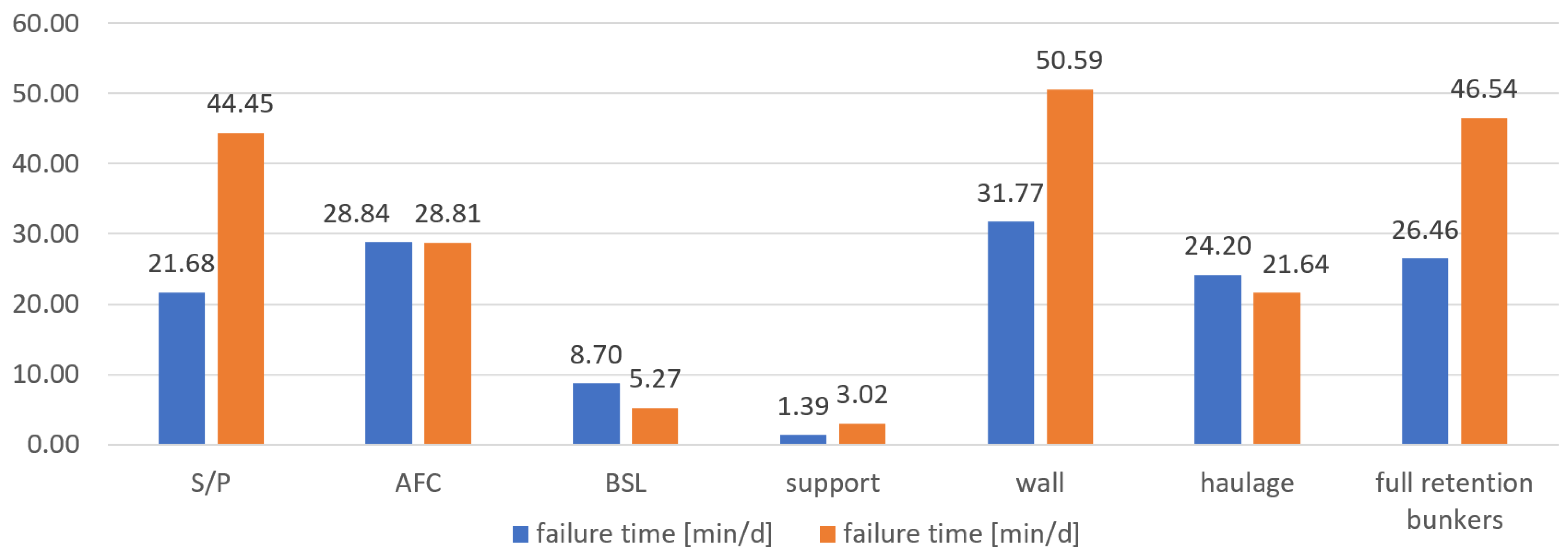
| Failure time [min/d] | S | 21.68 | 28.84 | 8.70 | 1.39 | 31.77 | 24.20 | 26.46 |
| P | 44.45 | 28.81 | 5.27 | 3.02 | 50.59 | 21.64 | 46.54 | |
| % | 105% | 0% | −39% | 117% | 59% | −11% | 76% | |
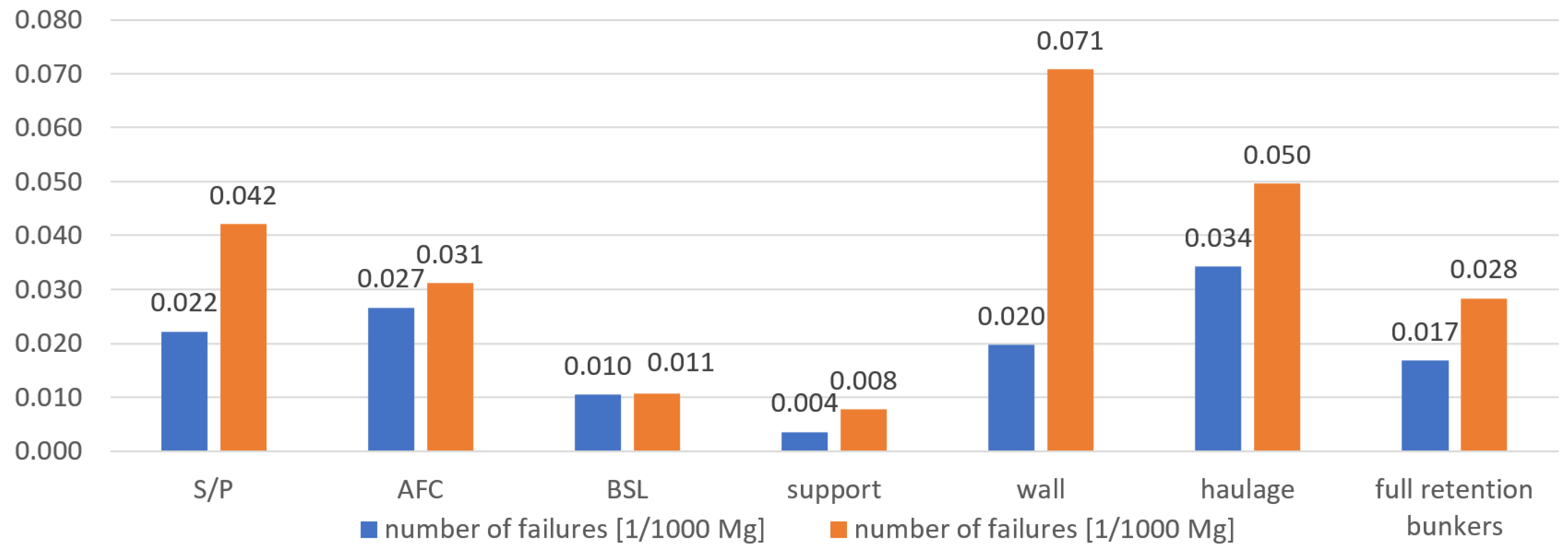
| Number of failures [1/thous. Mg] | S | 0.022 | 0.027 | 0010 | 0.004 | 0.020 | 0.034 | 0.017 |
| P | 0.042 | 0.031 | 0.011 | 0.008 | 0.071 | 0.050 | 0.028 | |
| % | 90% | 17% | 2% | 118% | 259% | 45% | 68% | |
| Failure time [min/thous. Mg] | S | 2.08 | 2.76 | 0.83 | 0.13 | 3.04 | 2.32 | 2.53 |
| P | 5.38 | 3.49 | 0.64 | 0.37 | 6.13 | 2.62 | 5.64 | |
| % | 159% | 26% | −23% | 175% | 101% | 13% | 122% |
Publisher’s Note: MDPI stays neutral with regard to jurisdictional claims in published maps and institutional affiliations. |
© 2022 by the authors. Licensee MDPI, Basel, Switzerland. This article is an open access article distributed under the terms and conditions of the Creative Commons Attribution (CC BY) license (https://creativecommons.org/licenses/by/4.0/).
Share and Cite
Bołoz, Ł.; Rak, Z.; Stasica, J. Comparative Analysis of the Failure Rates of Shearer and Plow Systems—A Case Study. Energies 2022, 15, 6170. https://doi.org/10.3390/en15176170
Bołoz Ł, Rak Z, Stasica J. Comparative Analysis of the Failure Rates of Shearer and Plow Systems—A Case Study. Energies. 2022; 15(17):6170. https://doi.org/10.3390/en15176170
Chicago/Turabian StyleBołoz, Łukasz, Zbigniew Rak, and Jerzy Stasica. 2022. "Comparative Analysis of the Failure Rates of Shearer and Plow Systems—A Case Study" Energies 15, no. 17: 6170. https://doi.org/10.3390/en15176170
APA StyleBołoz, Ł., Rak, Z., & Stasica, J. (2022). Comparative Analysis of the Failure Rates of Shearer and Plow Systems—A Case Study. Energies, 15(17), 6170. https://doi.org/10.3390/en15176170