Article

Variable Weighting Coefficient of EMF-Based Enhanced Sliding Mode Observer for Sensorless PMSM Drives

School of Electrical Engineering and Automation, Harbin Institute of Technology, Harbin 150001, China
*
Author to whom correspondence should be addressed.
Energies 2022, 15(16), 6001; https://doi.org/10.3390/en15166001
Submission received: 11 July 2022 / Revised: 2 August 2022 / Accepted: 10 August 2022 / Published: 18 August 2022
(This article belongs to the Special Issue Advanced Permanent Magnet Machines and Drives)

Abstract

:
In the field of permanent magnet synchronous motor (PMSM) control, the sliding mode observer (SMO)-based sensorless control is widely used; however, the actual control input of the current observation function is asymmetric. It can lead to different velocities of the estimated currents approaching to the actual currents and will make the current and back EMF fluctuations more severe, and result in more skewed angle and speed estimates, especially at a lower carrier ratio. In response to the above problems, this paper proposes a variable weighting coefficient of an EMF-based sliding mode observer (VWC-SMO). Unlike the traditional sliding mode observers, the weighted sliding mode switching variables and their bandpass-filtered values are used as the input of the current observer in the VWC-SMO. Thereby, the asymmetry of the control input in the current observation function can be well-suppressed, and almost the same approaching velocity on the two sides of the sliding surface can be obtained. Therefore, chattering near the sliding surface can also be suppressed. The method is verified on a motor controller experimental platform, and the comparative results shows that the VWC-SMO can reduce chattering of the observed currents and mitigate back EMFs fluctuations and improve the dynamic and steady-state performance.

1. Introduction

Due to the continuous progress and perfection of the utilization of electric energy, the permanent magnet synchronous motors (PMSMs) with many excellent properties have been widely applied in many areas. With more application scenarios and higher demands, much time and effort has been devoted to research in the field of sensorless control since the 1980s [1,2]. Mainstream sensorless control approaches can be divided into two categories: high-frequency injection methods based on detecting the response to this signal [3,4,5] and back electromotive force (EMF) methods based on various machine models [6,7,8,9,10,11,12,13,14,15,16,17,18,19,20,21,22,23,24,25,26,27,28,29].
The first method can only work well in a low-speed range, especially for the interior PMSM (IPMSM), but it has degraded performance for non-salient surface-mounted PMSM (SPMSM). On the contrary, the back EMF method is mainly applied for angle estimation in the technologies of high-speed motor control. At present, the most widely used back EMF methods mainly include the following: model reference adaptive system (MRAS) [6,7], Luenberger observer [8], sliding mode observer (SMO) [9,10,11,12,13,14,15,16,17,18,19,20,21,22], linear extended state observer (LESO) [23], disturbance observer [24], high-order sliding mode approach and nonlinear observer [25], extended Kalman filter (EKF) [26,27], etc. Among the above methods, the sliding mode observer is widely used in the field of sensorless control due to its good dynamic and static characteristics, good anti-disturbance, and other advantages.
In [9,10], the death compensation strategy is raised to reduce the harm of the inverter nonlinearity, so that the error of position estimation can be decreased. In addition, the flux spatial harmonics also affect the accuracy of position estimates [11,12,13,14,15,16,17]. The fifth and seventh harmonics are generally included in the back EMF observation, so that there will be sixth harmonics in the speed and angle estimates. Therefore, the adaptive notch filter (ANF) [11], the second-order generalized integrator (SOGI) [12], the recursive-least-square (RLS) adaptive filter [13], the bilinear recursive least squares (BRLS) adaptive filter [14], the adaptive hybrid generalized integrator (AHGI) [15], the adaptive synchronous filter (ASF) [16], and the frequency-adaptive complex-coefficient filter (FACCF) [17] are proposed, respectively, to extract the back EMF and enhance the accuracy of angle and speed estimation at high speed. For the sensorless control of interior PMSMs, an extended back EMF model is raised in [18], and the SMO is used to calculate the speed and angle in IPMSM drives [18,19].
In addition, the system performance will degrade because of the inherent characteristics of high-frequency vibration of the SMO; therefore, it is indispensable to reduce chattering to enhance the speed estimation accuracy. In order to improve the vibration of the traditional SMO, the saturation and sigmoid function are applied and compared in [20], as well as the super twisting algorithm in [21], which are proposed as the sliding mode switching functions to take the place of the conventional switching function. Additionally, an adaptive adjusting method for the sliding mode gain is proposed in [22]. The chattering can be improved by using such strategies to a certain degree. In recent years, the SMO has been applied in high-power and high-speed occasions, and because of the lower carrier ratio and greater delay of control, the chattering becomes severe and the current harmonics are more intense. A quasi-proportional resonant (QPR) controller-based adaptive observer is proposed in [28], and the discrete-time domain design is proposed in [29] which can enhance the accuracy of angle and speed estimation at a lower carrier ratio.
To suppress the chattering of the traditional sliding mode observer and improve the accuracy of the angle and velocity estimations in the sensorless PMSM drive at a lower carrier ratio, this paper proposes a variable weighting coefficient of an EMF-based sliding mode observer (VWC-SMO). The proposed observer can reduce the asymmetry of the control input in the current observation function by weighting the sliding mode switching variables and their bandpass-filtered values and can obtain almost the same approaching velocity on the two sides of the sliding surface. In this way, the chattering amplitude near the sliding surface can be effectively reduced. Comparative experiments of the proposed VWC-SMO and the traditional SMO under different PWM carrier ratios were carried out in a motor control experimental platform, and the results showed that the VWC-SMO can reduce chattering of the observed currents and back EMFs, so that it can improve the static and dynamic properties. Moreover, the simulation and experimental results showed good dynamic and steady-state performance of the VVC-SMO. In addition, compared with the methods mentioned in [20], the VVC-SMO method is easier to implement and has more advantages in the application of sensorless control.

2. SMO-Based Sensorless Control of PMSM

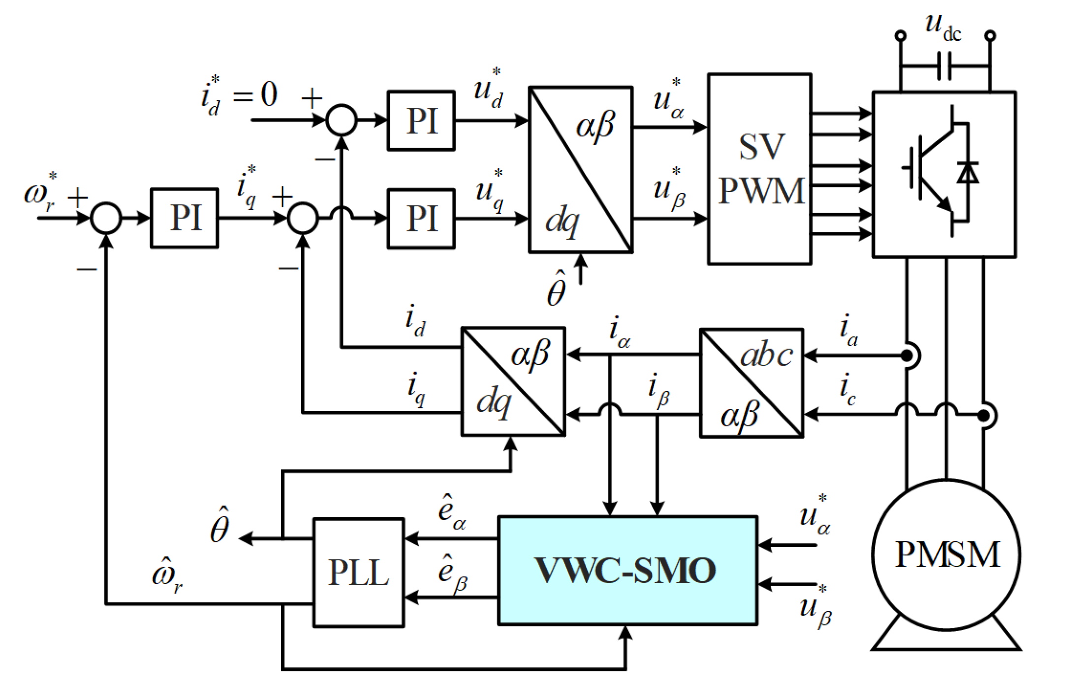
2.1. Field-Oriented Control of Position of Sensorless SPMSM

Figure 1 shows the control structure of sensorless motor control. The VWC-SMO replaces the traditional SMO in this system and uses the same inputs with the traditional SMO. The angle and speed are acquired by the normalized phase locked loop (PLL) based on the back EMFs observed by the VWC-SMO.

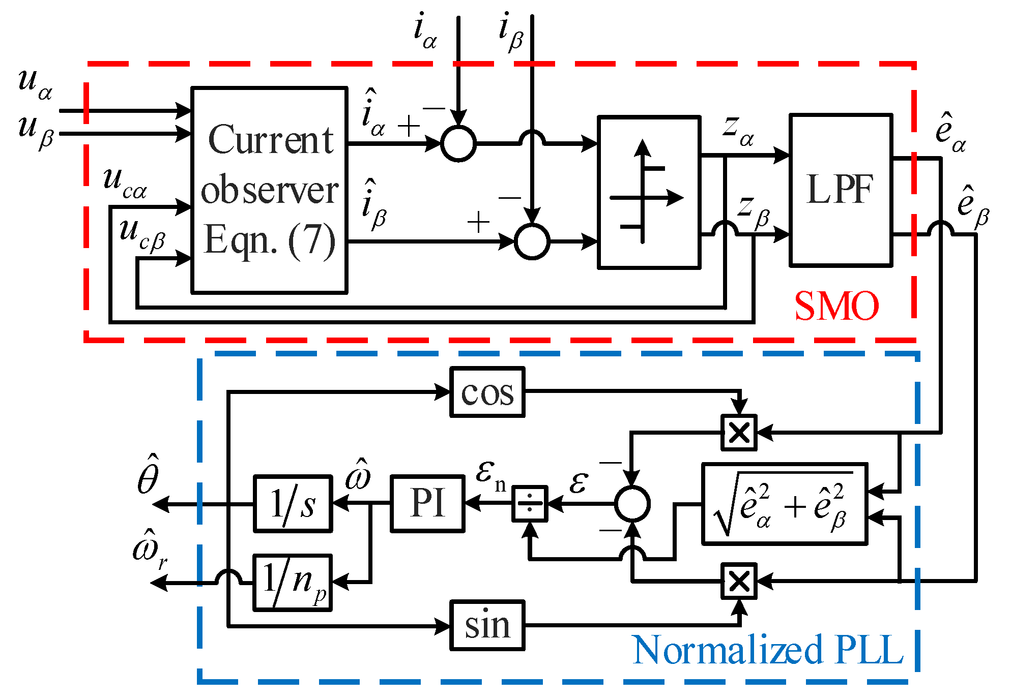
2.2. SMO-Based Position Estimation

Based on the theory of sliding mode variable structure control, the state of a control system as described in (1) can track the sliding surface as shown in (2) when the control input meets the condition of (3).
x ˙ = f ( x , u , t )
s ( x ) = 0
u ( x , t ) = u + ( x , t ) s ( x ) > 0 u ( x , t ) s ( x ) < 0
where x and u are the system state variable and the control variable, respectively. The symbol “·” means derivative of the variables. u+ and u indicate the control functions of both sides of the sliding surface, respectively. Under the action of the two control functions, the system can approach the sliding surface from both sides. That is to say, the system reaches the sliding mode control surface as:
s T s ˙ < 0
As for a SPMSM, the current state function in the α-β frame can be written as:
i ˙ = R L i + 1 L ( u e )
where i = [iα iβ]T is current, u = [uα uβ]T is voltage, e = [eα eβ]T are EMF vectors, and, iα, iβ are currents of α- and β-axis, uα, uβ are voltages, and eα, eβ are back EMFs. R is the stator resistance and L is the inductance.
The back EMFs can be expressed as:
e = e α e β = ω ψ f sin θ cos θ
where ω is the electric angular speed, ψf is the flux linkage, and θ is the rotor angle.
Based on (5), the SMO can be written as:
i ^ ˙ = R L i ^ + 1 L ( u u c )
where the sign “^” represents the estimated current values. uc = [u u]T, and u, u are the functions of sliding mode control of α and β axes, respectively.
According to (5) and (7), the error function can be acquired as:
Δ i ˙ = R L Δ i + 1 L ( e u c )
where Δ i = i ^ i = [ i ^ α i α i ^ β i β ] T = [ Δ i α Δ i β ] T indicates the current error, and it is usually chosen to be the sliding surface function, i.e.,
s = i ^ i = i ^ α i α i ^ β i β = 0
The sliding mode control function can have various control laws. Typically, the sign function as shown below is used as the sliding mode control function:
u c = z = z α z β = k 1 sgn ( i ^ α i α ) sgn ( i ^ β i β )
where sgn() stands for the sign function. k1 is the ratio, and there is k 1 > max e α , e β according to the sliding mode arrival condition as in (11) based on Lyapunov stability theory:
s T s ˙ = Δ i α Δ i ˙ α + Δ i β Δ i ˙ β < 0 , t > 0
Under the action of the control variables, i.e., zα and zβ, the current errors could approach to zero, and there are position and speed information in zα and zβ. Once the system states achieve the sliding surface, it used to be that the current errors were zero, so zα and zβ can be applied to obtain the value of the back EMFS through a low-pass filter, as:
e ^ α = LPF ( z α ) = ω c s + ω c z α e ^ β = LPF ( z β ) = ω c s + ω c z β
where ωc is the cutoff frequency of the LPF. The angle and position information can then be obtained from the back EMFs using the normalized PLL, as shown in Figure 2.

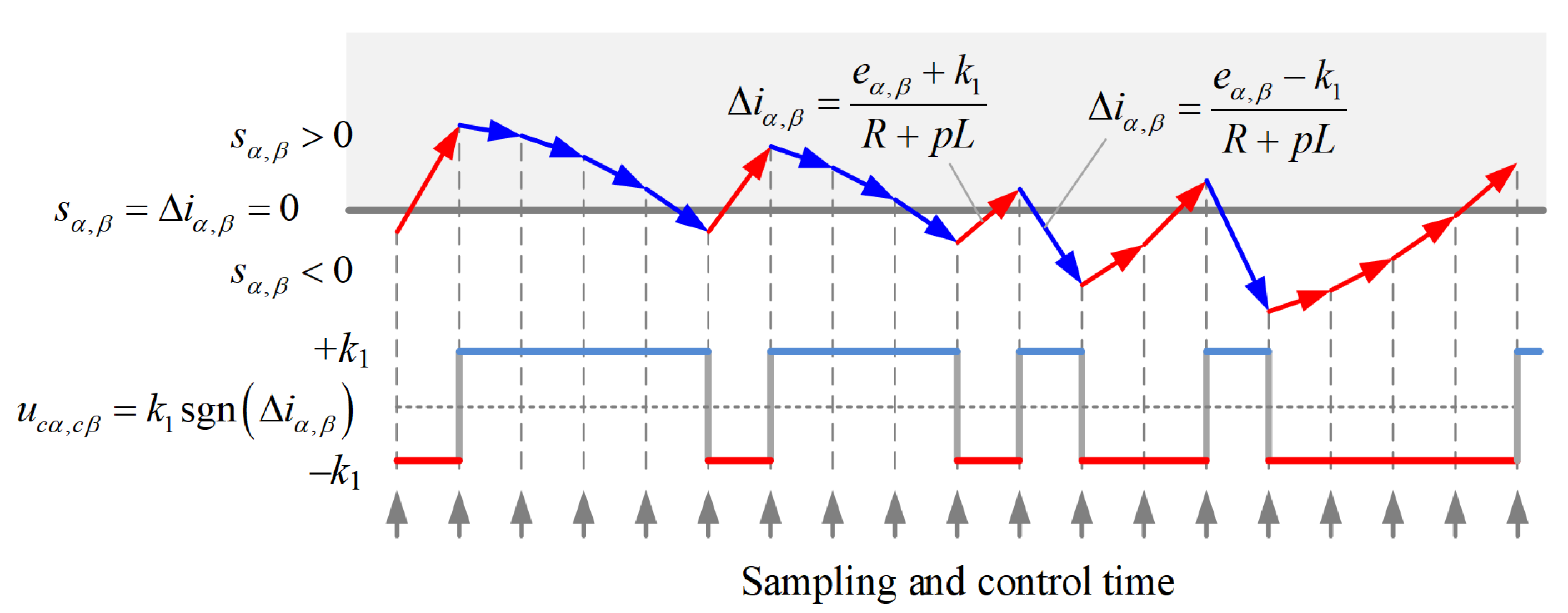
2.3. Asymmetric Approaching Velocity of SMO

According to (8), the sliding surface function can be written as:
s = Δ i = e u c R + p L = 0
where p stands for the differential operator. The current error is with a first-order inertia of the difference between back EMF and the switching function. Therefore, the actual control input is:
u ( x , t ) = e u c = e k 1 sgn ( i ^ i )
The sliding mode control function uc has two symmetric values, k1 or −k1, but the actual control variable u(x, t) has asymmetric values since the back EMF varies when the motor runs. Therefore, the effects on the current evolution are different, which leads to the asymmetric approaching velocity on two sides of the sliding surface. As shown in Figure 3, due to the discrete sampling and control in the actual digital system, the control variable uc will remain constant for the whole period. Thus, when the back EMF has a large positive amplitude, the positive control input (eα,β + k1) is much larger than the negative one (eα,βk1). Then, the current error could increase in the control period of (eα,β + k1) much more than the decrease in the period of (eα,βk1); that is, the current error could deviate even further from the sliding surface. Moreover, the difference of approaching velocity is even greater near the peak point of back EMF, since the actual control variable is severely asymmetric, which leads to more serious chattering at that time.
Figure 4 presents the simulation analysis results of the actual currents, the observed currents, and the practical sliding control variable under 5 and 1 kHz switching frequencies, respectively.
The speed is 600 r/m in Figure 4a. The fundamental frequency is 40 Hz, and the carrier ratio is 125 at this time. The speed is also 600 r/m in Figure 4b. The fundamental frequency is 40 Hz, and the carrier ratio is 25 at this time.
Near the peak of back EMF, the actual control input is far from zero at one side of the sliding surface, so the observed current can cross the actual current in one control cycle, but it cannot recover in a couple of coming control cycles since the control input is near zero at the other side of the sliding surface. The asymmetric approaching velocity increases the chattering of the observed current, and it is more deteriorating when the carrier ratio is reduced, as shown in Figure 4b. Then, the observed current chattering can lead to increased position and speed estimation errors.

3. Improved SMO Based on Variable Weighting Coefficient of Back EMFS
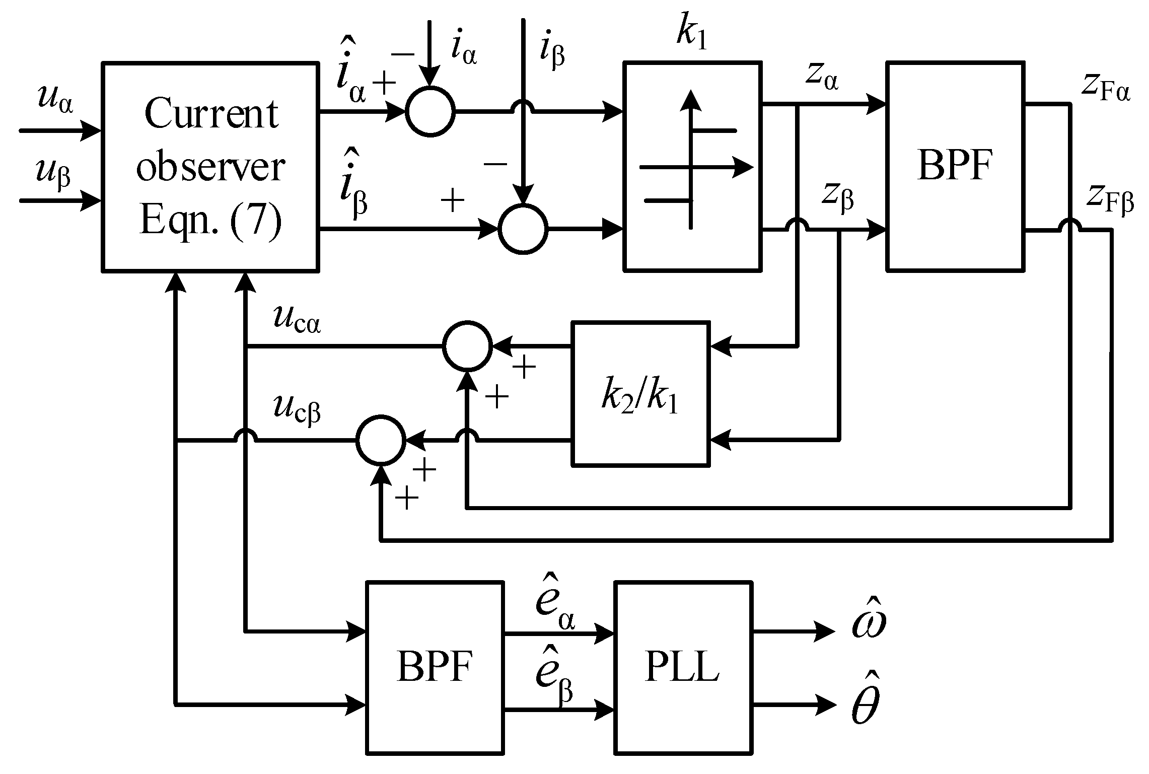
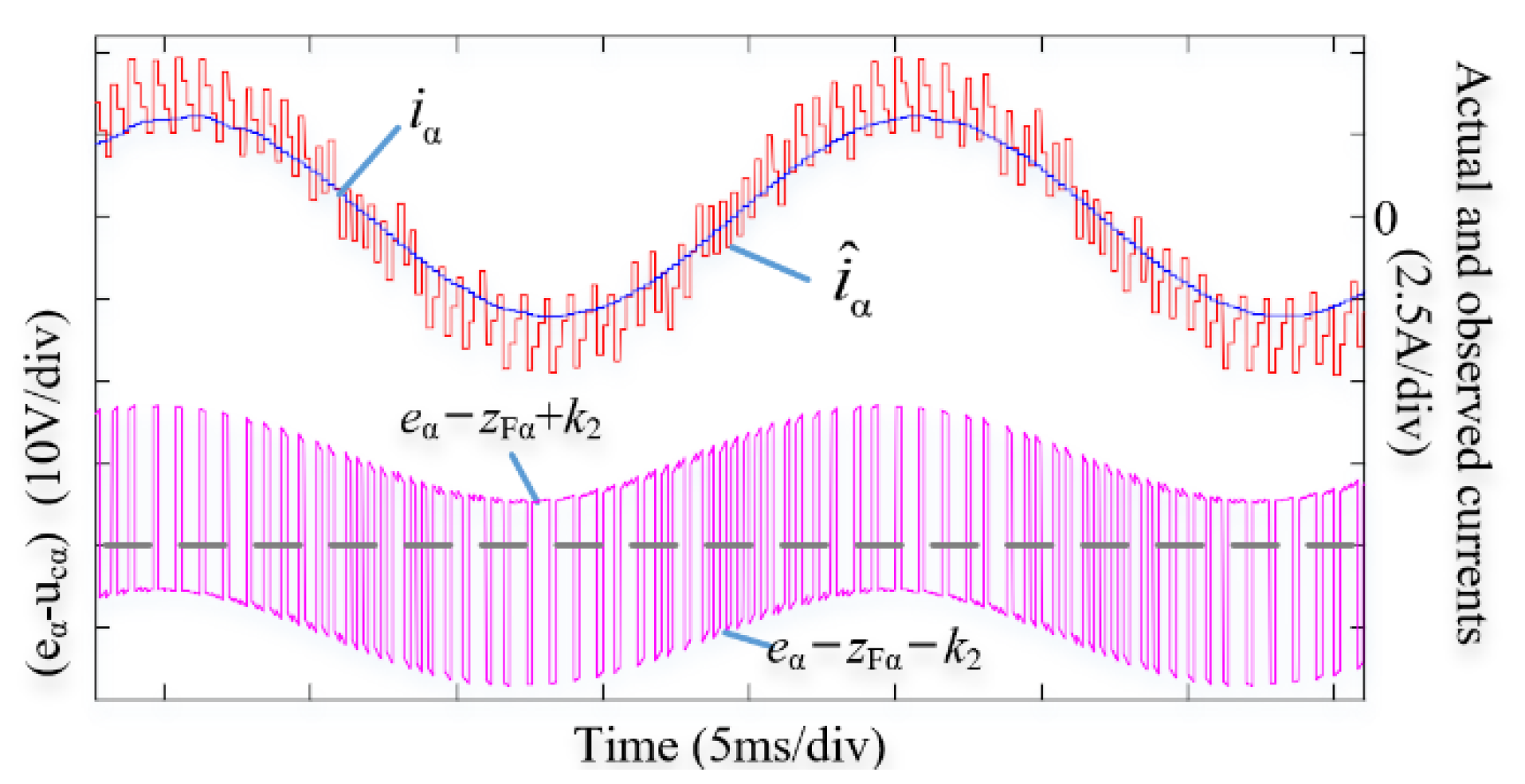
3.1. VWC-SMO

For improving the observed current chattering, the approaching velocity asymmetry on two sides of the sliding surface should be improved. Therefore, the actual control variable u(x, t) is assumed to be another symmetric sign function with gain k2. Thus, the sliding switching function can be written as (15) according to (14):
u c = e u ( x , t ) = e + k 2 sgn ( i ^ i )
In (15), the actual back EMF is unknown, and it can be replaced by the estimated value. To reduce the phase shift and amplitude attenuation of the estimated back EMF, a bandpass filter (BPF) as in (17) was employed instead of the LPF. Thus, the sliding mode switching function can be written as the weighted sum of the expected u(x, t) and the bandpass-filtered z; that is,
u c = k 2 sgn ( i ^ i ) + BPF k 1 sgn ( i ^ i ) = k 2 k 1 z + z F
where zF stands for the bandpass-filtered z. The control model of VWC-SMO is presented in Figure 5. The BPF can be written as:
G BPF ( s ) = 2 k BPF ω 0 s s 2 + 2 k BPF ω 0 s + ω 0 2
where KBPF is the adjustable coefficient of bandwidth and ω0 is the center frequency.

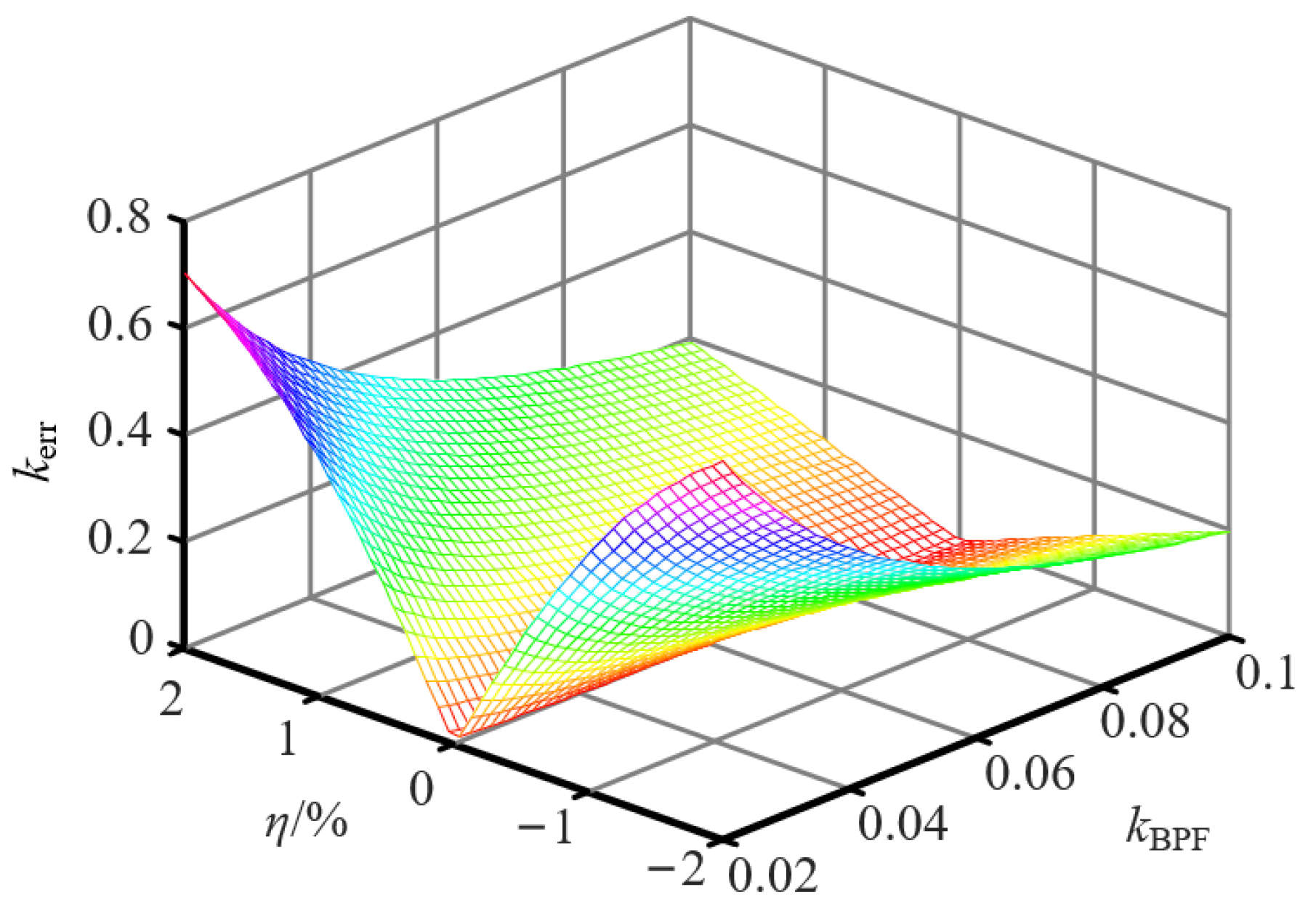
3.2. Parameter Design

In the steady-state condition, the fundamental value can be considered constant before and after filtering, and the control variable uc is equal to the back EMF. According to (16) and Figure 5, there is:
z F = k 1 k 1 + k 2 e
Combining (14), (16), and (18), the actual sliding mode control function and the arrival condition are described as (19) and (20), respectively.
u ( x , t ) = e u c = k 2 k 1 + k 2 e k 2 sgn ( i ^ i )
1 k 1 + k 2 max e α , e β < 1
Under dynamic conditions, considering that there is a back EMF error eerr, (18) can be rewritten as (21) and the sliding arrival condition can be expressed as (22):
z F = k 1 k 1 + k 2 e + e err
1 k 1 + k 2 max e α , e β + 1 k 2 max e err α , e err β < 1
The same as the traditional SMO, k1 is generally a constant bigger than the maximum of the back EMF. Similarly, k2 is designed as:
k 2 = k smo ω ^ ψ f
where ksmo is an adjustable coefficient. Along with the increase of ksmo, the robustness can be improved, but the chattering increases. To reduce the chattering, ksmo should be properly chosen.
The back EMF error is mainly caused by the BPF. When there is an error on the center frequency of the BPF, the back EMF error can be expressed as:
e err = ω ψ f sin θ A BPF sin ( θ φ BPF )
where ABPF and φBPF are the filter gain and phase shift at the real speed, respectively.
If the maximum back EMF error coefficient is defined as:
k err = max ( e err α , e err β ) ω ψ f
the relationship between the back EMF error coefficient Kerr and the BPF bandwidth coefficient KBPF, and speed error ratio η, can be presented in Figure 6. The diagram clearly shows that the error coefficient kerr is 0.707 if kBPF is selected the same as the speed error η. Therefore, kBPF should be selected as larger than the speed error η. Assuming that the speed error is ±2% and kBPF is 0.1, the back EMF error coefficient kerr is 0.198 according to Figure 6, and the parameter ksmo should be selected as 0.3.
The simulation results of the VWC-SMO are shown in Figure 7, and parameters of the SMO are set as above. In the proposed SMO system, the actual control input of axis α state observation function is (eαz ± k2) instead of (eα ± k1), and its asymmetry is reduced. Therefore, the observed current chattering can be suppressed.

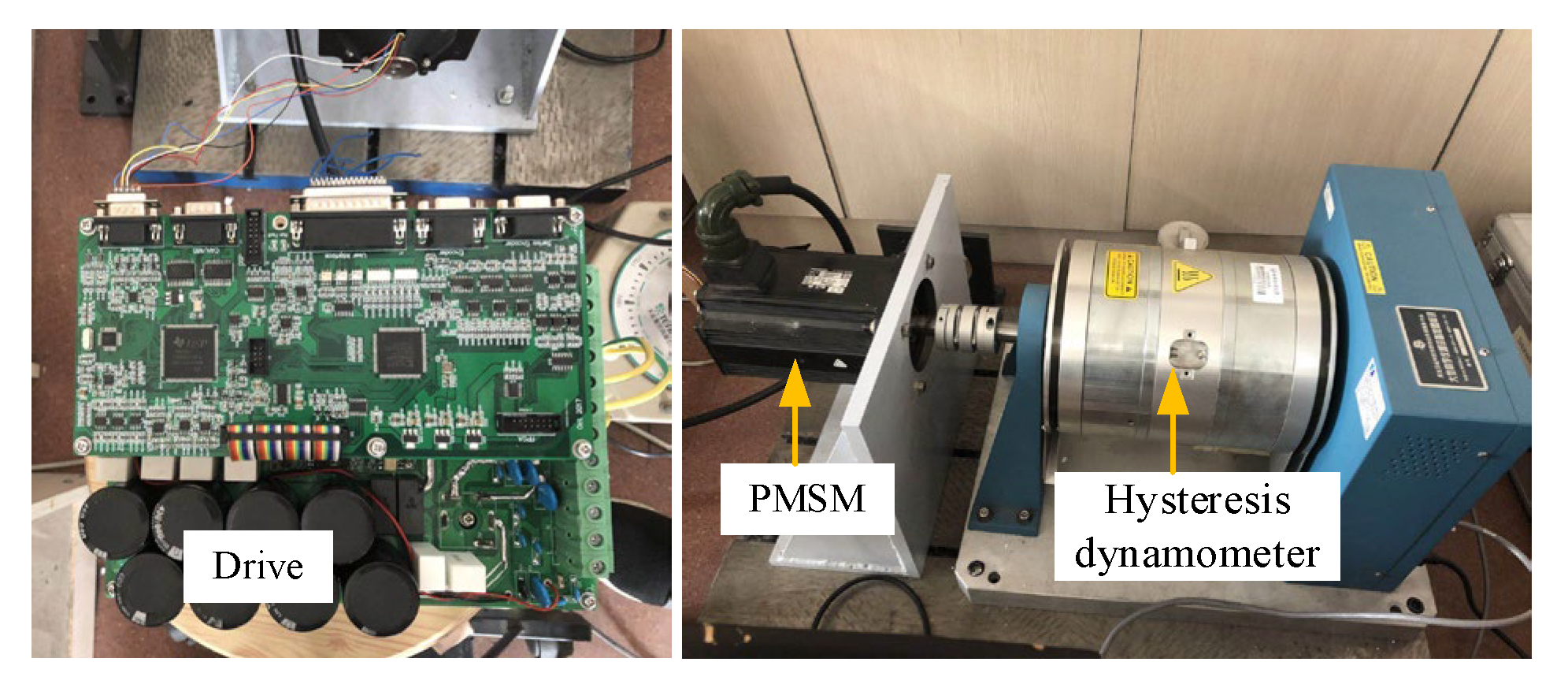
4. Experimental Results

The test platform of the proposed VWC-SMO is shown in Figure 8. The specific parameters of the motor applied in the experimental platform are presented in Table 1. The currents were sampled using the current sensor on the driver, and the rotor angle and speed information was sampled by the resolver installed on the motor and decoded by the decoding chip. The proposed VWC-SMO and the traditional SMO have carried out comparative experiments under high and low carrier ratios, and the dynamic and static performance of the VWC-SMO was also validated by the experiments.

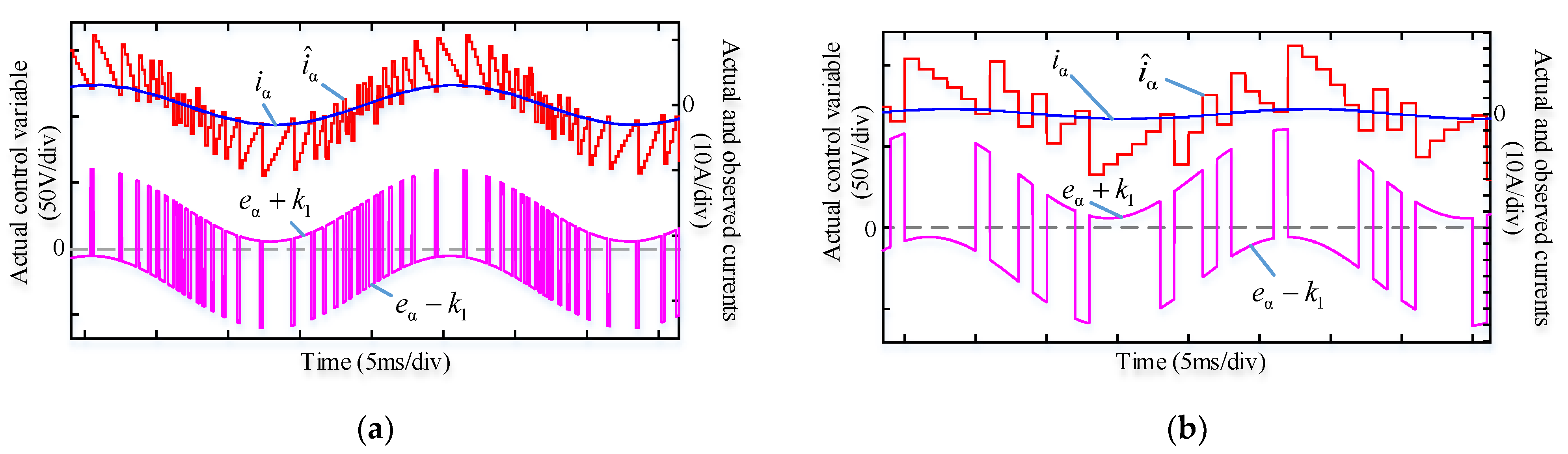
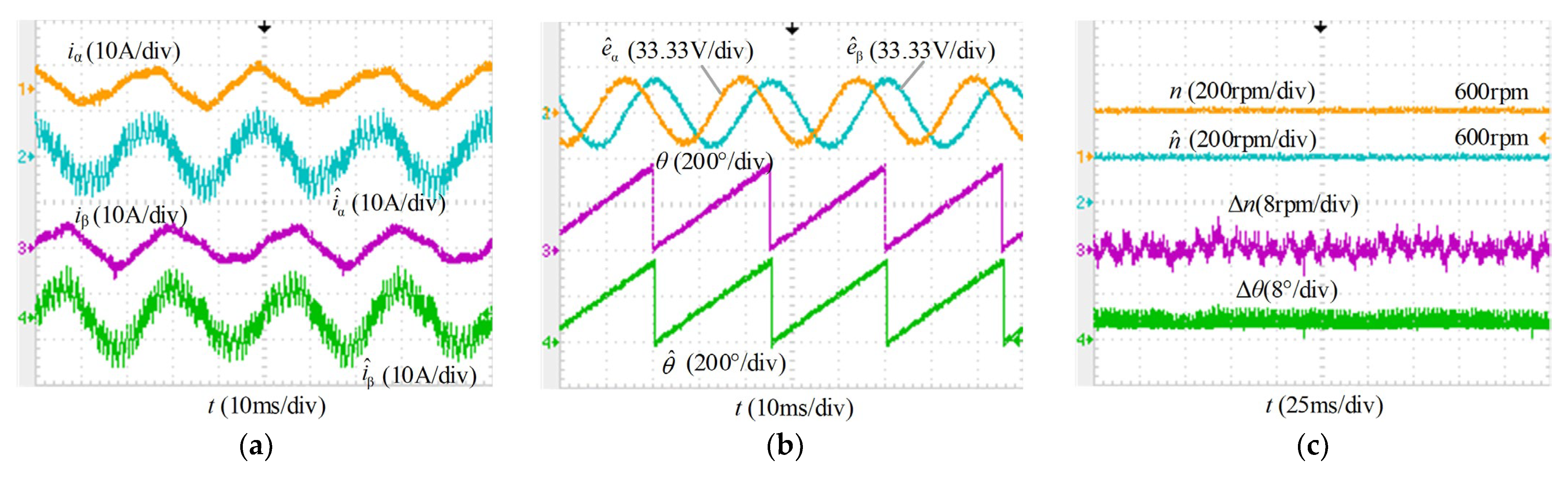
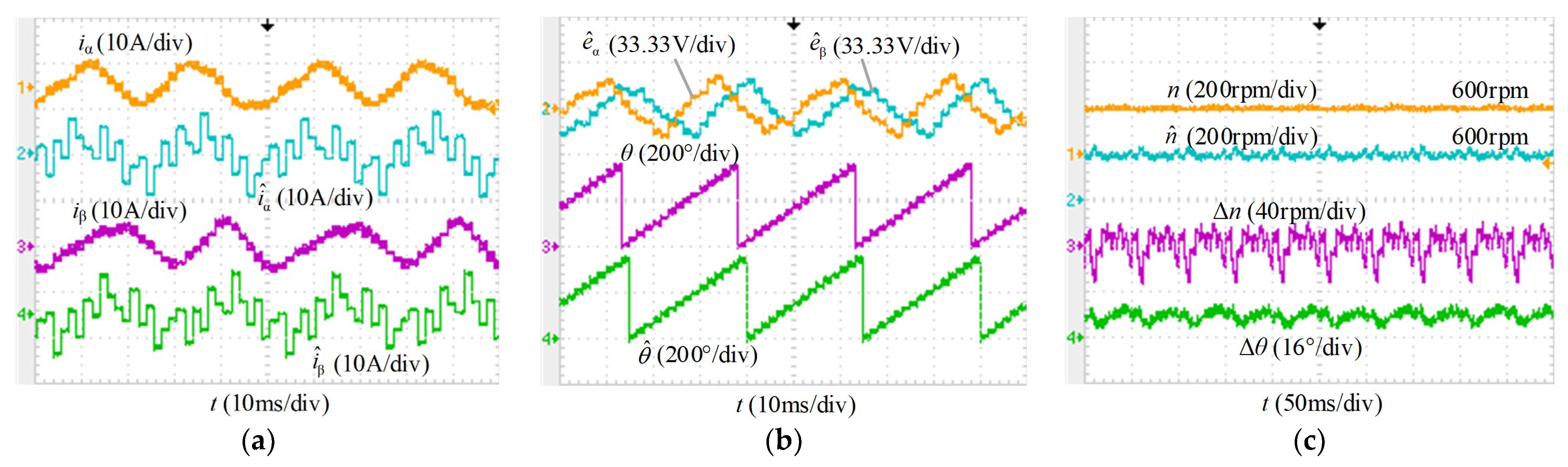
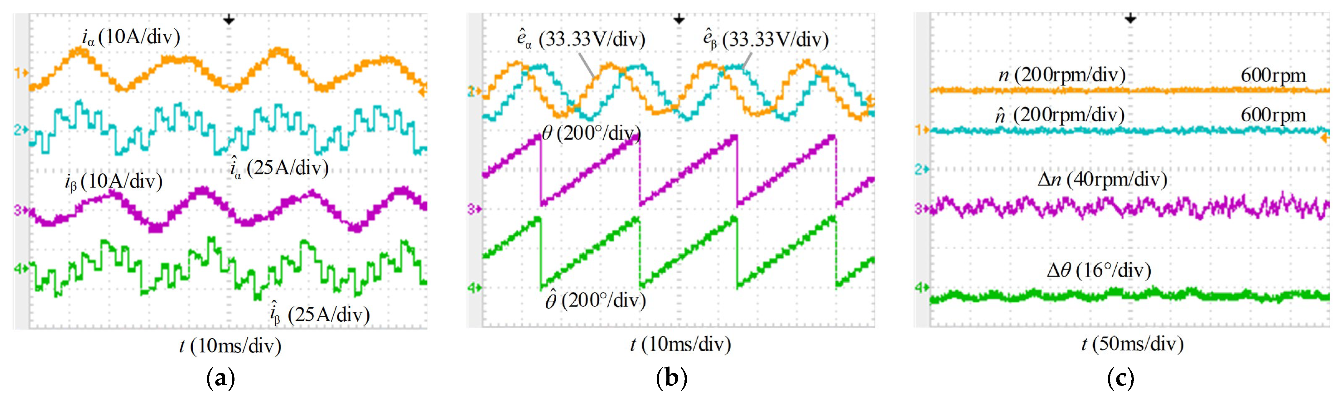
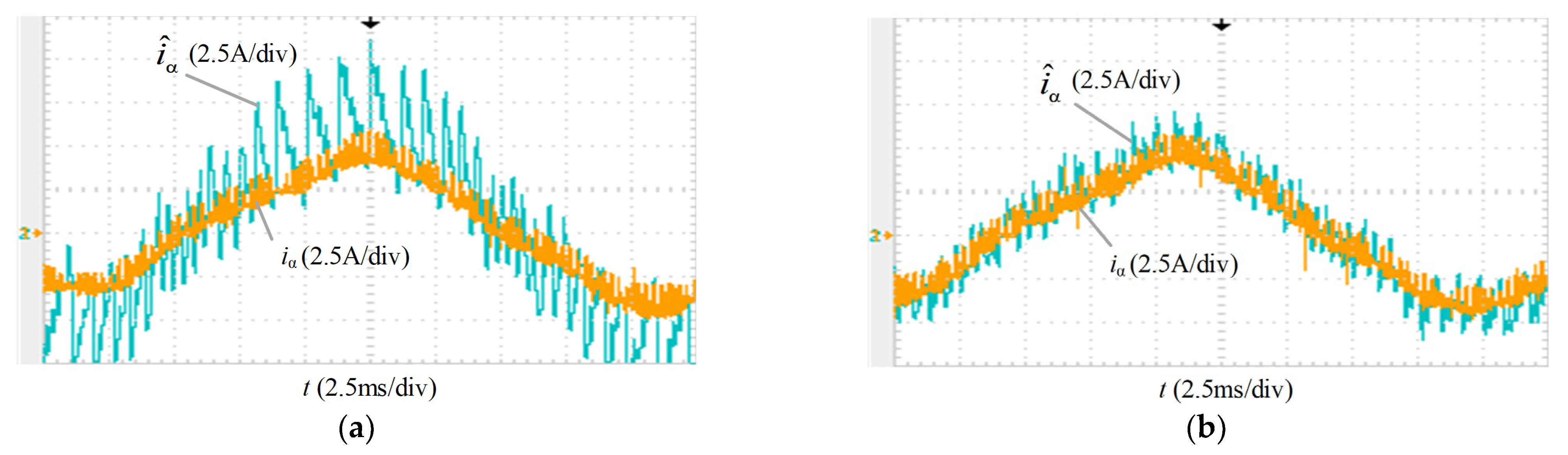
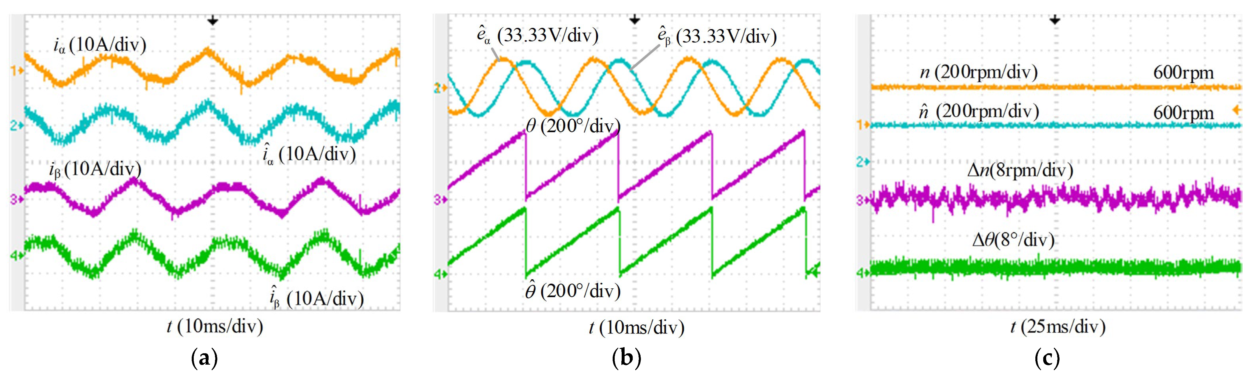
4.1. Steady-State Performance Comparison

Comparative experiments of the VWC-SMO with the traditional SMO were conducted when the speed of the motor was 600 r/min and the torque was 2 N·m. The switching frequencies are set to 5 kHz and 600 Hz, respectively, and the corresponding carrier ratios are 125 and 15, respectively. The actual effects of the traditional SMO are presented in Figure 9 and Figure 10, and the cutoff frequency of the low-pass filter was set to 2 times the motor angular speed. The results of the VWC-SMO are presented in Figure 11 and Figure 12.
The experiment of the traditional SMO at a 5 kHz switching frequency is presented in Figure 9. At this time, the base frequency was 40 Hz, and the carrier ratio was 25 at 600 rpm. Although the currents shown in Figure 9a have harmonics, the rotor information can be well-resolved from the back EMFs in the αβ frame, as shown in Figure 9b. The maximum error between the actual rotor angle and the estimated one was 6.1° and the maximum error of the speed value of the motor was 5.6 r/min, and all the waveforms can be seen in Figure 9c.
The experimental effects of the traditional SMO at a 600 Hz switching frequency are presented in Figure 10. At this time, the carrier ratio was 15. It can be seen from Figure 10a,b that the currents and back EMFs have more severe chattering and harmonics because of the lower carrier ratio. The maximum errors of the rotor angle and the speed reached 12.1°and 32 r/min, respectively, which can be seen in Figure 10c. This larger angle error and speed error have a serious adverse impact during the operation of the motor servo system, which will affect the system performance.
The experiment of the VWC-SMO proposed in this paper with a 5 kHz switching frequency is shown in Figure 11, and the VWC-SMO had an improved performance compared with the traditional SMO. The maximum angle and speed errors of the rotor reached 3.2° and 5.2 r/min, respectively.
The experimental results in Figure 12 show the VWC-SMO under a 600 Hz switching frequency. The chattering of estimated currents and back EMFs was reduced by using the VWC-SMO, as shown in Figure 12a,b. From Figure 12c, because of the lower carrier ratio, the maximum errors of the angle and speed expanded to 6.4° and 11.2 r/min, respectively. From 5 kHz to 600 Hz, it can be seen that although the experiments showed that the lower the carrier ratio, the larger the deviation of the observer estimate, the proposed observer still had good performance.
Figure 13 shows, in detail, the measured and observed currents with the traditional SMO and the VWC-SMO, respectively. In the traditional SMO, the observed current ripples severely near the peak of the current, which is caused by the different approaching velocity on the two sides of the sliding surface. However, the asymmetry of the sliding mode control variables can be reduced by the VWC-SMO and the current ripple can be mitigated, as shown in Figure 13b.

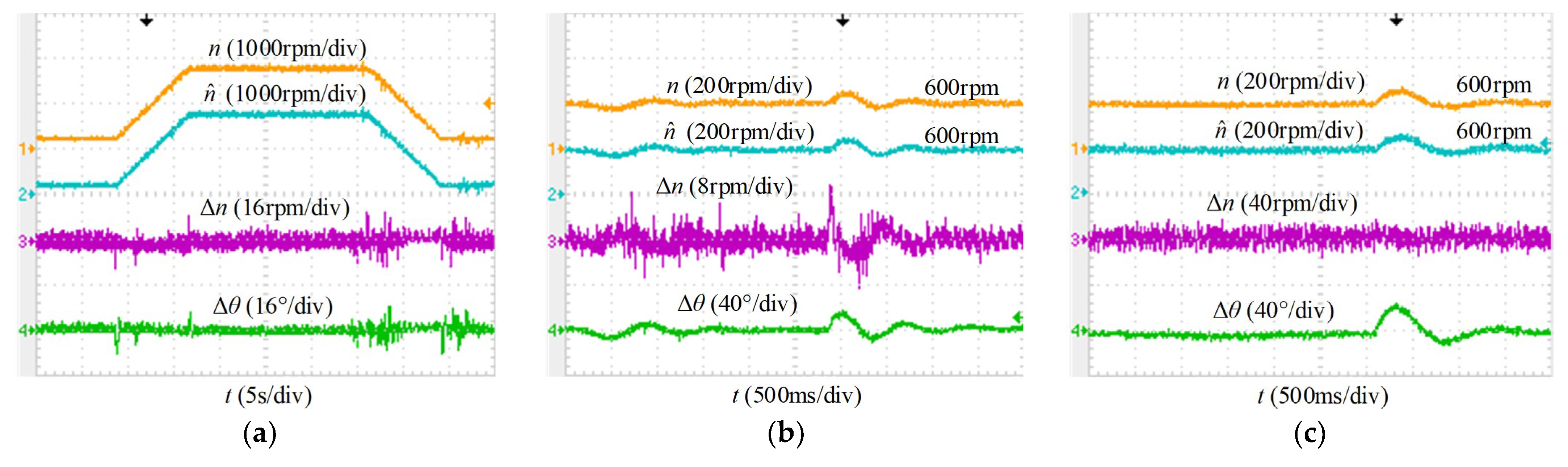
4.2. Dynamic Performance of the Proposed VWC-SMO

To verify the dynamic effect of the proposed VWC-SMO for angle and speed estimations, acceleration, deceleration, and changing load experiments in various states were conducted. Figure 14 shows the results. At a 5 kHz switching frequency, the motor speed was ramped up from 200 to 2000 r/min and then back down to 200 r/min. Figure 14a shows the real speed, estimated speed, and the errors of speed and angle. Obviously, VVC-SMO can track the real-time angle and speed very well when the motor is running. The speed error was less than 10 r/min, and the angle error was no more than 9°.
Figure 14b,c present the results of adding and subtracting the load experiment of the VWC-SMO under 5 kHz and 600 Hz switching frequencies, respectively. The motor first ran smoothly at 600 r/min, and then the load of the motor suddenly changed from 0 to 6 N·m; them, 3 s later, the load was back to 0 N·m again. When the motor was operating with sudden load changes, the speed and angle errors were, respectively, 9.6 r/min and 17° under a 5 kHz switching frequency. Under a 600 Hz switching frequency, the estimated speed and angle were 18 r/min and 22°, respectively. The experimental results for the sudden load of the motor during operation showed that the proposed VWC-SMO can effectively resist torque disturbance.

5. Conclusions

In applications with lower carrier ratios, the performance degradation of SMO makes it impossible to meet engineering needs. For improving the performance of SMO and reducing the estimation errors of angle and speed, this paper proposed a VWC-SMO. The new VWC-SMO can suppress the asymmetry of the sliding mode control variable on the two sides of the sliding surface, and then reduce distortion of the observed current. The experimental results on the experimental platform showed that the proposed method can effectively improve the angle and position estimation accuracy, especially under a low carrier ratio, and can virtually enhance the performance of the PMSM drives.

Author Contributions

Conceptualization, Q.A.; methodology, F.C. and J.Z.; software, J.Z.; validation, F.C.; investigation, M.Z. and S.L.; writing—original draft preparation, F.C.; writing—review and editing, F.C.; funding acquisition, Q.A. All authors have read and agreed to the published version of the manuscript.

Funding

This research received no external funding.

Institutional Review Board Statement

Not applicable.

Informed Consent Statement

Not applicable.

Data Availability Statement

Not applicable.

Conflicts of Interest

The authors declare no conflict of interest.

References

  1. Wang, G.; Valla, M.; Solsona, J. Position Sensorless Permanent Magnet Synchronous Machine Drives—A Review. IEEE Trans. Ind. Electron. 2020, 67, 5830–5842. [Google Scholar] [CrossRef]
  2. Stanica, D.M.; Bizon, N.; Arva, M.C. A brief review of sensorless AC motors control. In Proceedings of the 2021 13th International Conference on Electronics, Computers and Artificial Intelligence (ECAI), Pitesti, Romania, 1–3 July 2021; pp. 1–7. [Google Scholar]
  3. Lu, Q.; Wang, Y.; Mo, L.; Zhang, T. Pulsating High Frequency Voltage Injection Strategy for Sensorless Permanent Magnet Synchronous Motor Drives. IEEE Trans. Appl. Supercond. 2021, 31, 1–4. [Google Scholar] [CrossRef]
  4. Wang, G.; Kuang, J.; Zhao, N.; Zhang, G.; Xu, D. Rotor Position Estimation of PMSM in Low-Speed Region and Standstill Using Zero-Voltage Vector Injection. IEEE Trans. Power Electron. 2018, 33, 7948–7958. [Google Scholar] [CrossRef]
  5. Zhang, G.; Wang, G.; Wang, H.; Xiao, D.; Li, L.; Xu, D. Pseudorandom-Frequency Sinusoidal Injection Based Sensorless IPMSM Drives with Tolerance for System Delays. IEEE Trans. Power Electron. 2019, 34, 3623–3632. [Google Scholar] [CrossRef]
  6. Kivanc, O.C.; Ozturk, S.B. Sensorless PMSM Drive Based on Stator Feedforward Voltage Estimation Improved with MRAS Multiparameter Estimation. IEEE/ASME Trans. Mechatron. 2018, 23, 1326–1337. [Google Scholar] [CrossRef]
  7. Ni, Y.; Shao, D. Research of Improved MRAS Based Sensorless Control of Permanent Magnet Synchronous Motor Considering Parameter Sensitivity. In Proceedings of the 2021 IEEE 4th Advanced Information Management, Communicates, Electronic and Automation Control Conference (IMCEC), Chongqing, China, 18–20 June 2021; pp. 633–638. [Google Scholar]
  8. Andersson, A.; Thiringer, T. Motion Sensorless IPMSM Control Using Linear Moving Horizon Estimation with Luenberger Observer State Feedback. IEEE Trans. Transp. Electrif. 2018, 4, 464–473. [Google Scholar] [CrossRef]
  9. Zhao, Y.; Qiao, W.; Wu, L. Dead-Time Effect Analysis and Compensation for a Sliding-Mode Position Observer-Based Sensorless IPMSM Control System. IEEE Trans. Ind. Appl. 2015, 51, 2528–2535. [Google Scholar] [CrossRef]
  10. Wang, Y.; Xu, Y.; Zou, J. Sliding-Mode Sensorless Control of PMSM With Inverter Nonlinearity Compensation. IEEE Trans. Power Electron. 2019, 34, 10206–10220. [Google Scholar] [CrossRef]
  11. Wang, G.; Zhan, H.; Zhang, G.; Gui, X.; Xu, D. Adaptive Compensation Method of Position Estimation Harmonic Error for EMF-Based Observer in Sensorless IPMSM Drives. IEEE Trans. Power Electron. 2014, 29, 3055–3064. [Google Scholar] [CrossRef]
  12. Sun, S.; Cheng, H.; Wang, W.; Liu, H.; Mi, S.; Zhou, X. Sensorless DPCC of PMLSM Using SOGI-PLL Based High-Order SMO with Cogging Force Feedforward Compensation. In Proceedings of the 2021 13th International Symposium on Linear Drives for Industry Applications (LDIA), Wuhan, China, 1–3 July 2021; pp. 1–7. [Google Scholar]
  13. Wang, G.; Li, T.; Zhang, G.; Gui, X.; Xu, D. Position Estimation Error Reduction Using Recursive-Least-Square Adaptive Filter for Model-Based Sensorless Interior Permanent-Magnet Synchronous Motor Drives. IEEE Trans. Ind. Electron. 2014, 61, 5115–5125. [Google Scholar] [CrossRef]
  14. Wu, X.; Huang, S.; Liu, K.; Lu, K.; Hu, Y.; Pan, W.; Peng, X. Enhanced Position Sensorless Control Using Bilinear Recursive Least Squares Adaptive Filter for Interior Permanent Magnet Synchronous Motor. IEEE Trans. Power Electron. 2020, 35, 681–698. [Google Scholar] [CrossRef]
  15. Kashif, M.; Murshid, S.; Singh, B. Adaptive Hybrid Generalized Integrator Based SMO for Solar PV Array Fed Encoderless PMSM Driven Water Pump. IEEE Trans. Sustain. Energy 2021, 12, 1651–1661. [Google Scholar] [CrossRef]
  16. Jian, H.; Song, W. A sliding mode observer of IPMSM combining adaptive synchronous filter and back EMF estimator. In Proceedings of the 2020 7th International Forum on Electrical Engineering and Automation (IFEEA), Hefei, China, 25–27 September 2020; pp. 121–126. [Google Scholar]
  17. An, Q.; Zhang, J.; An, Q.; Liu, X.; Shamekov, A.; Bi, K. Frequency-Adaptive Complex-Coefficient Filter-Based Enhanced Sliding Mode Observer for Sensorless Control of Permanent Magnet Synchronous Motor Drives. IEEE Trans. Ind. Appl. 2020, 56, 335–343. [Google Scholar] [CrossRef]
  18. Chen, Z.; Zhang, H.; Zhang, Z. EEMF-based Sensorless control for IPMSM Drives with an Optimized Asymmetric Space Vector Modulation. In Proceedings of the 2019 22nd International Conference on Electrical Machines and Systems (ICEMS), Harbin, China, 11–14 August 2019; pp. 1–5. [Google Scholar]
  19. Yin, Z.; Zhang, Y.; Cao, X.; Yuan, D.; Liu, J. Estimated Position Error Suppression Using Novel PLL for IPMSM Sensorless Drives Based on Full-Order SMO. IEEE Trans. Power Electron. 2022, 37, 4463–4474. [Google Scholar] [CrossRef]
  20. Petro, V.; Kyslan, K. A Comparative Study of Different SMO Switching Functions for Sensorless PMSM Control. In Proceedings of the 2021 International Conference on Electrical Drives & Power Electronics (EDPE), Dubrovnik, Croatia, 22–24 September 2021; pp. 102–107. [Google Scholar]
  21. Liang, D.; Li, J.; Qu, R. Sensorless Control of Permanent Magnet Synchronous Machine Based on Second-Order Sliding-Mode Observer with Online Resistance Estimation. IEEE Trans. Ind. Appl. 2017, 53, 3672–3682. [Google Scholar] [CrossRef]
  22. Yang, C.; Ma, T.; Che, Z.; Zhou, L. An Adaptive-Gain Sliding Mode Observer for Sensorless Control of Permanent Magnet Linear Synchronous Motors. IEEE Access 2018, 6, 3469–3478. [Google Scholar] [CrossRef]
  23. Yu, B.; Shen, A.; Chen, B.; Luo, X.; Tang, Q.; Xu, J.; Zhu, M. A Compensation Strategy of Flux Linkage Observer in SPMSM Sensorless Drives Based on Linear Extended State Observer. IEEE Trans. Energy Convers. 2022, 37, 824–831. [Google Scholar] [CrossRef]
  24. Indriawati, K.; Widjiantoro, B.L.; Rachman, N.R.i. Disturbance Observer-Based Speed Estimator for Controlling Speed Sensorless Induction Motor. In Proceedings of the 2020 3rd International Seminar on Research of Information Technology and Intelligent Systems (ISRITI), Yogyakarta, Indonesia, 10 December 2020; pp. 301–305. [Google Scholar]
  25. Belkhier, Y.; Shaw, R.N.; Bures, M.; Islam, M.R.; Bajaj, M.; Albalawi, F.; Alqurashi, A.; Ghoneim, S.S. Robust interconnection and damping assignment energy-based control for a permanent magnet synchronous motor using high order sliding mode approach and nonlinear observer. Energy Rep. 2022, 8, 1731–1740. [Google Scholar] [CrossRef]
  26. Gopinath, G.; Das, S.P. An extended Kalman filter based sensorless permanent magnet synchronous motor drive with improved dynamic performance. In Proceedings of the 2018 IEEE International Conference on Power Electronics, Drives and Energy Systems (PEDES), Chennai, India, 18–21 December 2018; pp. 1–6. [Google Scholar]
  27. Tondpoor, K.; Saghaiannezhad, S.M.; Rashidi, A. Sensorless Control of PMSM Using Simplified Model Based on Extended Kalman Filter. In Proceedings of the 2020 11th Power Electronics, Drive Systems, and Technologies Conference (PEDSTC), Tehran, Iran, 4–6 February 2020; pp. 1–5. [Google Scholar]
  28. An, Q.; Zhang, J.; An, Q.; Shamekov, A. Quasi-Proportional-Resonant Controller Based Adaptive Position Observer for Sensorless Control of PMSM Drives Under Low Carrier Ratio. IEEE Trans. Ind. Electron. 2020, 67, 2564–2573. [Google Scholar] [CrossRef]
  29. Zhang, G.; Wang, G.; Xu, D.; Yu, Y. Discrete-Time Low-Frequency-Ratio Synchronous-Frame Full-Order Observer for Position Sensorless IPMSM Drives. IEEE J. Emerg. Sel. Top. Power Electron. 2017, 5, 870–879. [Google Scholar] [CrossRef]
Figure 1. Position of sensorless field-oriented control of PMSM drive.
Energies 15 06001 g001
Figure 2. SMO and normalized PLL-based angle and speed estimation.
Energies 15 06001 g002
Figure 3. Asymmetric approaching velocity on both sides of the sliding surface in the traditional SMO.
Energies 15 06001 g003
Figure 4. Simulation analysis results of SMO at switching frequencies of (a) 5 and (b) 1 kHz.
Energies 15 06001 g004
Figure 5. Block diagram of the proposed VWC-SMO.
Energies 15 06001 g005
Figure 6. The relationship between kerr and η, and kBPF.
Energies 15 06001 g006
Figure 7. Simulation results of the VWC-SMO at a 5 kHz switching frequency.
Energies 15 06001 g007
Figure 8. Test platform.
Energies 15 06001 g008
Figure 9. Experimental waveforms of the traditional SMO under a 5 kHz switching frequency. (a) Currents. (b) Estimated back EMFs and angle. (c) Speed and angle.
Energies 15 06001 g009
Figure 10. Experimental waveforms of the traditional SMO under a 600 Hz switching frequency. (a) Currents. (b) Estimated back EMFs and angle. (c) Speed and angle.
Energies 15 06001 g010
Figure 11. Experimental waveforms of the VWC-SMO under a 5 kHz switching frequency. (a) Currents. (b) Estimated back EMFs and angle. (c) Speed and angle.
Energies 15 06001 g011
Figure 12. Experimental waveforms of the VWC-SMO at a 600 Hz switching frequency. (a) Currents. (b) Estimated back EMFs and angle. (c) Speed and angle.
Energies 15 06001 g012
Figure 13. Actual and observed currents at a 5 kHz switching frequency. (a) The traditional SMO. (b) The VWC-SMO.
Energies 15 06001 g013
Figure 14. Dynamic experimental waveforms. (a) Speed up and down under a 5 kHz switching frequency. (b) Speed and angle errors in addition and subtraction load under a 5 kHz switching frequency. (c) Speed and angle errors in addition and subtraction load under a 600 Hz switching frequency.
Energies 15 06001 g014
Table 1. Specific parameters of the experimental platform.
ParameterSymbolValue
Rated powerPN (kW)3.0
Rated currentIN (A)17.8
Rated torqueTeN (N·m)14.3
Rated speednN (r/min)2000
Winding resistanceR (Ω)0.1
d-axis inductanceLd (mH)1.5
q-axis inductanceLq (mH)1.5
PM flux linkageψf (Wb)0.11
Number of pole pairsnp4
Rotor inertiaJ (kg·m2)0.00223
DC link voltageUdc (V)300
Dead timeTd (μs)3
Publisher’s Note: MDPI stays neutral with regard to jurisdictional claims in published maps and institutional affiliations.

