Abstract
In this paper, we present a low-cost health assessment system for oil-immersed service transformers using a monitoring device to measure energy in real time. By assessing the important level of transformer components, three indicators, top oil temperature, vibration, and transformer load, were selected as main indicators to investigate the service transformer’s condition. An evaluation system using Fuzzy logic method is also presented in the paper to support monitor transformer health without adding the extra cost of installing expensive sensors. Different testing scenarios with different case studies were carried out on a simulated 50 kVA oil-immersed service transformer to express the feasibility and effectiveness of this low-cost, fast response health assessment system.
1. Introduction
In the power system, transformers are one of the key components [1]. Some of the main reasons for failures include leaking oil, broken insulation, overload, voltage spikes, and unbalanced loading. Consistent failures could shorten transformer life or cause power outages [2,3]. For those reasons, effective methods need to be developed to keep track of the overall transformer’s condition so that the failures and degradation can be proactively mitigated by the operators, helping to increase the reliability of power quality and reduce the operations and maintenance cost for utilities. There are four main types of transformers in the power system, which are shown in Figure 1.
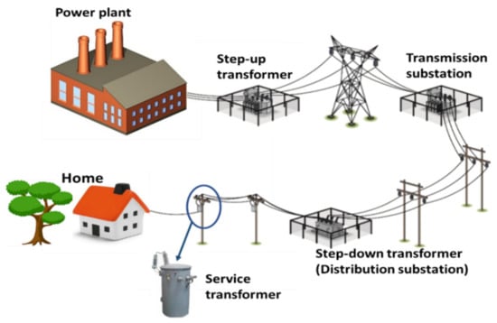
Figure 1.
Location of service transformer in the power system.
- -
- A step-up transformer: the generated energy in power plants has low voltage and high current value. The step-up transformers are usually used in all generating plants to support stepping up the voltage supply from a low level to a higher level for efficient electricity transmission [4].
- -
- Transmission substation is used to connect two or more transmission lines with multiple transmission voltage levels. If all transmission lines have the same voltage, the transmission substation will be used to connect or isolate the transmission lines for fault clearance or maintenance [5,6].
- -
- A step-down transformer or distribution substation is used to convert the high voltage level of the transmission lines to a lower voltage level and adapt it to the distribution grid.
- -
- A service transformer is the final voltage transmission step in the distribution grid. This type of transformer is applied to convert the voltage of the distribution grid level to home level. The nominal power of this type of transformers is usually below 1 MVA.
Transformer health monitoring implemented by utilities is an important process that could help improve the reliability by continuously checking on the most critical transformer’s components and predict the unexpected fault to avoid sudden breakdowns or extend the transformer’s life [7,8,9,10]. Most recent research focuses on the monitoring programs, which are carried out on large power transformers and distribution substations at high voltages [11,12,13]. In [9], three methods of Dissolved Gas Analysis were proposed to evaluate the power transformer health and experiments were presented on 50 MVA transformers. The authors of [14] used 19 diagnostic indicators and 4-years historical data from 1256 132 kV-transmission transformers and 3 single-phase 500 kV transformers in Malaysia to evaluate the tested transformers’ condition. In [15,16], a method was proposed to assess the transformer states based on the health indices regression line, which is plotted from health index data analysis of power transformers’ population. It is obvious that large power transformers are of more interest. These power transformers perform the coordination of large power flows in the whole system; they play an extremely important role. A small fault on a transformer can cause a system-wide outage and affect all adjacent lower voltage levels in the system. There are two kinds of monitoring approaches: offline monitoring and online monitoring. The offline monitoring approach is carried out in routine schedule and requires the full disconnection of the transformer from the grid to preform testing while the online approach can be implemented with the same sensitivity without interrupting the transformer’s operation. Because the online approach could overcome the offline test limitations to enhance the transformer’s operation and reliability with a lower cost, this paper will focus on online monitoring approaches.
While the other substations are huge and expensive to maintenance, the service transformers have a much lower price. It is also because of the low cost that the service transformers are often not regularly maintained, but will be replaced when there is a breakdown. This way of management consumes a lot of equipment replacement costs for the utility side, and sometimes the emergency transformers also cause overvoltage, resulting in damage to the user’s equipment. This explains why not much research on health assessment for low-voltage transformer or service transformer has been carried out. In [17], a method was presented that uses the Artificial Neural Network to estimate the oil temperature from a transformer’s voltages and currents, then estimates the life reduction of a considered 45 kVA vegetable oil distribution transformer. In [18], a remote condition monitoring technique using inputs such as temperature, oil level, transformer loading, and humming sound was carried out to identify the condition of a distribution transformer. In [19], a wireless monitoring program using measured ambient temperature, voltage, and current was proposed to evaluate the distribution transformer condition every 90 s. In [20], a transformer health monitoring system was designed based on five measurable parameters and the image of a 15 kVA/400 V low-voltage transformer. The system requires four sensors on the transformer tank and one camera at the top of transformer. All of the mentioned approaches are still quite complicated, and require the installation of additional sensors on the transformers, which will add extra costs to monitor the low-voltage service transformers.
In this paper, a low-cost health assessment system, an online monitoring health method for an oil-immersed service transformer, is proposed. Instead of using multiple sensor devices to assess the transformer’s conditions, this system uses only one energy measuring device combined with a transformer monitoring program to assess the actual condition and then transmit the final results to the operator. Top oil temperature, vibration, and transformer loading were selected as desired parameters. Fuzzy logic is used to combine various indicators of transformer health into an overall health index. Algorithms are run centrally on the server to scan the operational characteristics and suggest the requirements for maintenance, reconfiguration, or replacement. A simple, low-cost service transformer monitoring program will contribute to reduced damage, increase grid reliability, and help operators better manage transformers and make proper maintenance and replacement decisions in a reasonable way.
Main contribution of the paper:
- -
- Investigate the importance of transformers’ components and then select the most effect indicators to assess the condition of service transformers.
- -
- Propose an online assessment system using the Fuzzy logic evaluation model that responds quickly to the variations of inputs to monitor service transformer health using real measurements without adding expensive sensors and interrupting transformer operation.
The paper is structured in the following sections: Section 2 will introduce the structure of an oil-immersed service transformer and determine the most important monitoring parameters. Section 3 presents the models which are used to estimate the transformer’s inputs. Section 4 will describe the online monitoring system for service transformers. The proposed monitoring system will be applied on a simulated transformer in Section 4. The results will be analyzed to show the effectiveness of the proposed system. Section 5 is the conclusion.
2. Structure of an Oil-Immersed Service Transformer and Selection of Monitoring Indicators
The transformer is used to transfer the electrical power from one circuit to the other circuit without changing the frequency. The main parts of a simple electric transformer include a transformer core and two inductive coils: primary winding and secondary winding, as shown in the Figure 2a. The primary winding is connected to the input power supply and the secondary winding is connected to the load. The transformer core conducts a magnetic flux through the core and links between the primary coil and secondary coil. The transformer core is made using iron, which is a high-magnetic-permeability material. The core of the transformer conducts a magnetic flux through the core and transmits the power in the transformer coils. However, to be safe and more reliable for a wide range of power transformers, the transformer’s core and windings are set in a transformer tank with additional accessories [21]. In this paper, we only consider the oil-immersed transformer.
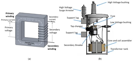
Figure 2.
(a) Transformer structure and (b) structure of a single-phase oil-immersed service transformer.
Different transformers will have different sizes and complexities; however, the working principles and the main parts are the same. The basic structure of an oil-immersed service transformer is shown in Figure 2b. The main additional components are the transformer tank, insulating oil, bushing, and tap changer.
- -
- The transformer tank is the physical component which is used to protect the transformer core and windings. It is also an oil container to cool down the transformer.
- -
- Insulating oil is an insulation for core and windings.
- -
- Bushing is applied to provide insulation when the terminals are routing through the tank to connect the transformer with the electric network.
- -
- The tap changer is applied to adjust the transformer’s output voltage. For low-voltage service transformers, it is impossible to change the when the transformers are energized; the change could be implemented after the transformer is isolated from the grid.
Based on the structure of the transformer, different research investigations are performed to locate the causes of the transformer failures to prevent these breakdowns. In [22], a model is presented that highlights the main failure components as core, insulation, winding, bushing, and transformer tank. The same is stated in [23,24,25,26]. In [27], the overall transformer condition is evaluated based on 15 input parameters; the paper also showed the importance of the insulation parameters in the transformer health assessment process. In [3], the authors focus on the failures that happened the most to the distribution transformers. After reviewing all the research, the importance rank of the various transformer component failures was summarized in Figure 3. It can be seen that the most important components which impact transformer health ideally could be a set of electrical, mechanical, and thermal, and are located inside the transformers. Other components such as the cooling system, tap changer, or lack of maintenance have less of an effect. These critical failures could be hard to locate non-invasively and require expensive sensors to monitor [28,29]. These sensors need to work precisely and are tough to install without interrupting the transformer operations, which is why they have not been deployed previously on the service transformers. Any potential monitoring methodologies which are inexpensive and simple to set up are of immediate interest.
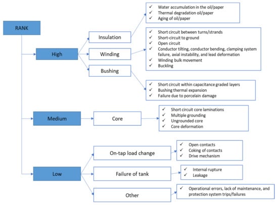
Figure 3.
Ranking of transformer components failures.
3. Assessment Indicators for Service Transformers
After reviewing the literature, the authors selected three main parameters, top oil temperature, vibration, and transformer loading, to assess the service transformer health. Transformer indicators are approximated based on the current, voltage, and ambient temperature at the service transformer and the final health assessment at the central server is sent to the operators. The estimation methods which are applied to approximate the assessment indicators are shown below.
3.1. Top Oil Temperature Estimation
Top oil temperature (θoil) represents the thermal state of the transformer. Usually, a temperature sensor will be installed near the conductor of the transformer to measure the highest temperature of the winding. However, this method is not widely used due to its high cost and difficulty in implementation [30]. The top oil temperature is not measured directly from the service transformer, but is rather determined using an IEEE thermal model based on measured ambient temperature, voltage, and current at the transformer’s energy monitoring device [31]. It can be expressed in the equation below:
where:
- Δθoil is is the rise of the top oil temperature at the current conditions, °C
- Δθoil,R is the rise of the top oil temperature at the rated conditions, °C
- Set R represents the ratio of the core’s heat generation to the winding’s heat generation at rated load
- K represents the load factor
- τTO is the time constant, hour
- n is the oil exponent. The value of n can be in the range from 0.8 to 1. Details of the calculation method can be found in the references [32,33].
3.2. Vibration Estimation
The vibration and noise of the transformer play a critical role in determining the transformer quality [34]. That is why the authors selected vibration as one of the key indicators to evaluate the condition of the service transformer. Vibration is produced mainly at the service transformer’s winding and the core. Normally, vibration for power transformers can be estimated using very complex computational models. In this paper, the monitoring object is a service transformer with small size and power capacity; therefore, the vibration estimation model can be applied in a much simpler way. The electrodynamic forces and the magnetic forces are in proportion to the current squared and voltage squared, respectively [35]. The transformer tank vibration could be estimated using the equation below [22,36]:
where α, β, γ, and δ are coefficients which are determined based on transformer geometry; u is the transformer’s voltage; and i is the transformer’s current.
νtank = (α + β*θoil)*i2 + (γ + δ*θoil)*u2
3.3. Transformer Loading
The loading (TL) of a service transformer is calculated by dividing the measured load to the testing transformer’s nameplate rating power. If the transformer is overloaded in a period of time, the unexpected failures may occur. These failures could break the transformer’s insulation or damage the coils inside the transformer. Therefore, it was chosen as a key parameter to access the transformer conditions.
4. The Online Monitoring System for Service Transformers
To collect the transformer’s indicators, an energy monitoring device needs to be set up to record voltage, current, and ambient temperature every second. The monitoring device consist of a microcontroller that records grid information and estimate assessment indicators then send data to the central gateway device via wireless radio-frequency module. The online monitoring program gathers data from energy monitoring device, detects transformer health index, and then presents results to the operator through a user interface. Figure 4 shows the online monitoring system diagram.
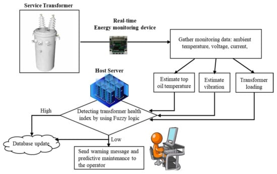
Figure 4.
Scheme diagram of the online monitoring system.
For transformer health assessment, several main techniques are studied such as fuzzy logic, machine learning, and health index calculation. The health index calculation method needs to be integrated with experience parameters, and it is difficult to deliver accurate results [37]. Machine learning could provide high accuracy results but requires large amounts of historical data of the transformer [38]. In this paper, fuzzy logic, which represents vague concepts, was chosen to solve problem where the conventional methods cannot be applied effectively [39,40,41]. The control system of this technique has three steps: fuzzification, inference, and defuzzification [42]. The system model is described in Figure 5. The system’s basic structure is illustrated in Figure 6.
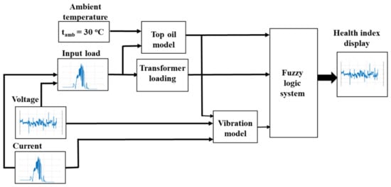
Figure 5.
The model of the assessment system.
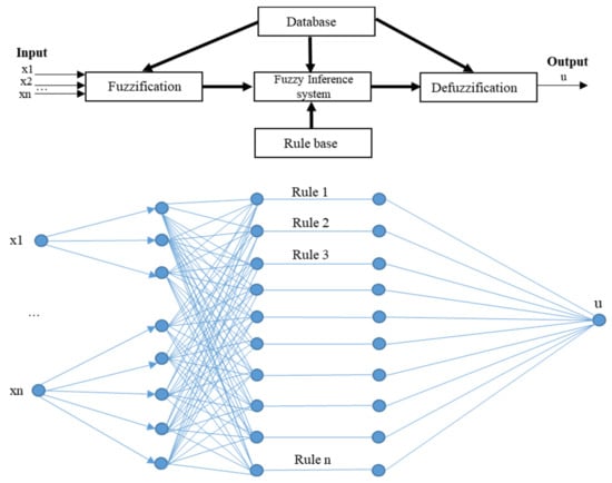
Figure 6.
The basic structure of fuzzy control system.
The Fuzzy’s membership functions are assigned to values of each input, indicating “good”, “average”, “poor”, and “very poor” statements. The respective ranges are described in trapezoidal curves as expert rules. The top-oil temperature is the highest priority, as it is the most important part for assessing the condition of the insulation. Vibration and transformer loading are lower-priority inputs. The final output is the overall transformer condition or health indices (HI). In this paper, the limit ranges of the input parameters are derived from the IEEE and IEC standard [3,32,43]. Table 1 presents fuzzy memberships of input variables including transformer loading, top oil temperature, and vibration. The fuzzy output health indices are also expressed in this table. The expert rules are established as a result of the critical order of inputs to estimate the health condition for the service transformer. The expert rules are shown in Table 2.

Table 1.
Limit Ranges and Fuzzy Memberships.
Table 2.
Fuzzy logic expert rules for assessing health indices.
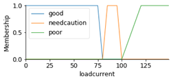
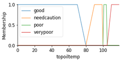
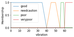
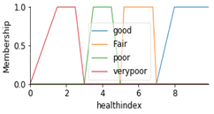
Figure 7 presents an example of how the Fuzzy membership inputs look. In this example, if a transformer is loading 146% transformer capacity, that means the transformer loading is in the “poor” condition (black line in green area of Figure 7a); the estimated top oil temperature at 77 °C indicates the “good” condition (black line in blue area of Figure 7b); the current vibration of the transformer is 45 dB in the “needs caution” condition. Based on the expert rules presented in Table 2, the Fuzzy output—health index can be approximated at six, meaning the transformer is currently in the “fair” condition.
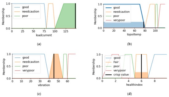
Figure 7.
An example of Fuzzy control system operation. (a) Fuzzy membership inputs of transformer loading; (b) Fuzzy membership inputs of top oil temperature; (c) Fuzzy membership inputs of vibration; (d) Fuzzy membership output of Health index.
The program was executed in the PYTHON environment. The advantage of this system is its quick response to the small variation in the inputs, and the minimal processing burden. The computation time is very fast: just in 0.042 s. To prove that these Fuzzy memberships work properly and evaluate the accuracy of the proposed model, more details can be found in the simulation results section.
5. Simulation Results and Discussion
To show the effectiveness of the service transformer’s monitoring system and the sensitivity of the outputs to the small changes of the transformer’s inputs, a simulated 50 kVA service transformer was tested. Currently, this transformer is rated in “Good” operating condition. At rated load, the top oil temperature rise is 65 °C. The weight of the oil is 105 kg, the transformer core weight is 70 kg, and the transformer tank weight is 165 kg. The load loss of the considered transformer is 870 W and no-load loss is 130 W. Assuming the ambient temperature on all that dates is 30 °C, two test scenarios were implemented:
- -
- Scenario 1: Evaluate the transformer health using 1-day data to evaluate the sensitivity of the monitoring program to the abnormal changes in the transformer. The electrical parameters were aggregated using an energy monitoring device on 1 November 2019. Three sub-cases were implemented in this scenario to compare the results.
- -
- Scenario 2: Evaluate the transformer health using 2-week data. Basically, the assessment of transformer condition requires long-term observation to assess the actual condition of the transformer and not just based on temporary and unstable evaluation results. This is important in making the final decision as to whether to repair or replace the transformer. The electrical conditions on the transformer were measured in December of 2019.
5.1. Evaluate the Transformer Health Using 1-Day Data
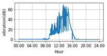
From Equations (1) and (2), it can be seen that all the variation in the transformer loading rate (presented by the transformer’s current and voltage) leads to the changing of the transformer’s top oil temperature and vibration. As mentioned, three sub-cases with different conditions were carried out to investigate the response from the system.
- -
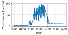
- Case 1: The transformer works at normal condition. The peak transformer load is mostly changing in the range from about 40% to 80% rated capacity of the transformer.
- -
- In case 2 and case 3, the transformer’s load profile is modified to check how the output health index will change in new conditions:
- -
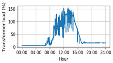
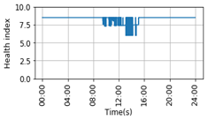
- Case 2: Transformer is assumed to be in “Fair” operating condition. The peak transformer load is simulated to change in the range from about 50% to 150% rated capacity from 12:00 pm to 1:30 pm. The overload doesn’t happen continuously, but it is “on”, “off” in some period of time.
- -
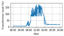
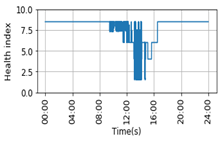
- Case 3: Transformer is assumed to be in “Poor” operating condition. It is worse than case 2 and is worst-case, which could happen to any old transformer. The peak transformer load is simulated to change in the range from about 100% to 150% rated capacity in a longer period of time from 9:00 am to 1:30 pm, equivalent to the operating data of an old transformer.
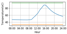
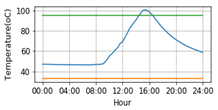
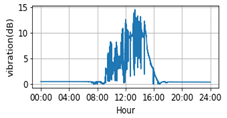
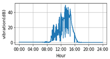
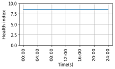
The data in Case 1 are the real recorded data from a power monitoring device. It is hard to collect data of the “Fair” and “Poor” transformers because not all old service transformers are equipped with power monitoring devices or most of those transformers were replaced to ensure the power quality for consumers. Therefore, the data in Case 2 and Case 3 were simulated and adjusted based on the data from Case 1 to see how the proposed monitoring system reacts to the different situations. The test results of three cases are expressed in Table 3. It can be seen that with each different loading profile, the archived profile of top oil temperature and vibration are different. In case 1, the top oil transformer only raised under 70 °C, and vibration is very minor, under 15 dB. For the whole day, the transformer was assessed in the “Good” operating condition, and the health index is stable at 7, equivalent to the “Good” condition, which is matched with the originally given expected condition. Based on the action recommendation in Table 1, the transformer only needs the “Normal maintenance”. In case 2, the top oil temperature obviously increased to 90 °C at around 3:30 PM and vibration increased to over 40 dB when the transformer was over load by almost 150%. This could happen for transformers that have not been designed to match the load capacity or with older transformers due to the weakening of the insulation after a long operation time. The transformer health index went down to six at some points to show that the transformer needs to be observed more carefully or increase diagnostic testing. In case 3, with a long time overloading, the top oil temperature went up to 100 °C, over the IEEE standard limit 95 °C. The vibration was at some point in the “very poor” condition (higher than 60 dB). The health index decreased to two, meaning that the transformer needs to be immediately assessed for risk.
Table 3.
Test results of scenario 1.
Based on the results acquired from the proposed system with the simulated transformer’s condition, it was proved that the applied model has a good response to any changes of inputs and an accurate health assessment was provided to the operator. In case 3, while the assuming condition of transformer is “Poor” condition, at some time step, the system will send a “Very Poor” assessment to the operator. In this case, it is necessary to observe the transformer for a longer time to make sure that the transformer is in “Poor” condition or in “Very Poor” condition. It should be noted that the proposed monitoring program only provides recommendation actions. The final evaluations will be given by the operators after further necessary risk assessments have been performed based on the recommended warning messages sent.
5.2. Evaluate the Transformer Health Using 2-Week Data
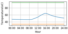
Because the service transformers do not have load tap changers, the transformer’s monitoring results could be directly impacted. Long-term observation for transformer health assessment is necessary. In this part, the author will evaluate the actual condition of the transformer based on 2-week observation data. The same “Good” condition transformer in the 1-day data testing case is applied. The result of the evaluation process is shown in Figure 8.
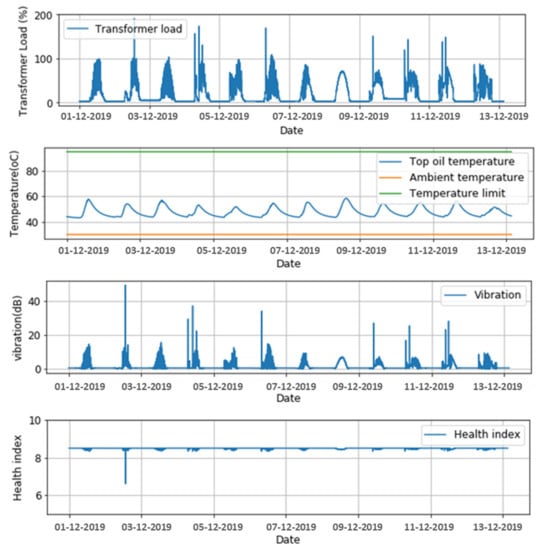
Figure 8.
Test results of Scenario 2.
The HI is stable around 8.5. On 2 December, there an event happened which lead to increased transformer loading to almost 200%, vibration at almost 50 dB, and the top oil temperature remaining under 60 °C and not changing much. The overall heal assessment at that point is “Fair” condition. If the operators only accessed the 1-day evaluation on 2 December, they may have thought that the transformer needed to be taken care of to avoid any accident. However, looking at the whole assessment results in 2 weeks, it can be seen that the event is just an irregular fault which does not happen often. The overall health index in 2 weeks is “Good” condition. No special care is required beyond the regular maintenance in this case.
Service transformers are the final voltage transformation components in the distribution network, which are often quite similar in capacity and size; therefore, this evaluation model can be widely applied to many same-capacity range service transformers in the grid. The transformer condition assessment system is fully automated. The advantages of this model are low costs, simplicity, and ease of use. With the widespread development of the current smart grid, most transformers have synchronous energy-measuring devices, and this will be a good opportunity to apply this evaluation model into practice, enhance the ability to manage service transformers, and save operation costs for power companies.
While other methods take a long time to evaluate and require high costs to install the expensive sensors, the proposed method provides a quick assessment result in as little as 0.042 s and could be tailored according to the needs of the operator. Real-time assessments can provide the fastest visual results to the operator, but it is not required. Because some measuring devices only allow the next day’s measurement data to be collected, the model can be modified to perform daily transformer condition assessment and then update the results to the operator’s data system.
To access the precision of the proposed method, the 67 operating transformers which were managed by Cam Giang Power company (CGC) in Hai Duong, Vietnam were tested for each 30-min period over a 24-h period to check the transformer health conditions. The final calculated health indices by the proposed method and CGC are presented in Table 3. These transformers were installed in the period of time from 2003 to 2021. To derive each transformer health index, CGC implemented a test program for all current operating transformers. Some transformers have the same installation year, but the actual health condition of transformer may be different due to the results of the load pattern or differences in maintenance plans. However, the details of the health calculation indice method was not revealed in their final report. The health indices provided by CGC were divided into three groups: Good (G—for health index value from 8 to 10), Moderate (M—for health index value from 4–7), and Bad (for health index value from 1 to 3).
Since it is impossible to list all the estimated inputs for each 30-min period over a 24-h period, the results obtained by the presented method seen in Table 4 are the results at the time when each transformer condition was the worst and were compared with those provided by CGC. The comparison had to be conducted carefully in order to take into consideration the fact that utility indices were based on crisp numbers, whereas this paper was based on the fuzzy-logic technique, which use linguistic manipulation. It is important to note that the presented method has a different number of health condition categories, good, fair, poor, and very poor, while the utility’s health indices are good, moderate, and bad. To facilitate the comparison, the “Poor” and “Very poor” index conditions produced by the fuzzy-logic method were compared with the bad category from the utility’s calculation.
Table 4.
Health index calculation for transformers 1 to 21 at CGC.
Based on the comparison from Table 5, there are 6 cases in 67 cases where the proposed method’s results are not the same as the CGC’s results, which denotes that the outcomes are a 91.04% match.
Table 5.
Comparison result produced by the proposed method and CGC.
6. Conclusions
In this paper, an online oil-immersed service transformer health monitoring system has been presented using a real-time energy monitoring device. A novel fuzzy logic evaluation model is introduced and tested on a simulated 50 kVA oil-immersed service transformer. The three main parameters selected for transformer health assessment were top oil temperature, transformer load, and vibration. After comparing the evaluation results from the proposed model with the original assumptions, it could be seen that the initiated non-invasive method provides relatively accurate results and fast computation time in the range of less than 1 s, while the investment cost is low with minimal disruption. Therefore, this model is efficient, reliable, and easily implemented by utilities and industrial facilities to obtain the health readings of their transformers, which is an advantage. Significantly, electric vehicles and solar power are being increasingly integrated into the distribution grid. Service transformers are the first to be affected due to the variability and unpredictability. Setting up a low-cost monitoring application will play an important role in this case to help power companies have early suitable upgrade solutions for the rapidly changing grid.
For further work, this model can be applied on different service transformers with different capacities, and high-accuracy sensors for transformer’s oil and windings will be installed on the tested transformer to analyze the sensitivity of the transformer’s indicators and provide the overall validation.
Author Contributions
Conceptualization, Q.T.T. and L.R.; methodology, Q.T.T.; software, Q.T.T.; validation, Q.T.T., B.D.V. and Q.N.N.; writing—original draft preparation, Q.T.T.; writing—review and editing, Q.T.T. and L.R.; project administration, L.R. All authors have read and agreed to the published version of the manuscript.
Funding
This research received no external funding.
Institutional Review Board Statement
Not applicable.
Informed Consent Statement
Not applicable.
Data Availability Statement
Not applicable.
Conflicts of Interest
The authors declare no conflict of interest.
References
- Transformers: Basics, Maintenance, and Diagnostics; Bureau of Reclamation: Denver, CO, USA, 2005.
- Chitnavis, K.; Bhasme, N.R. Review of critical analysis for life estimation of power transformer. In Proceedings of the 2017 4th International Conference on Power, Control & Embedded Systems (ICPCES), Allahabad, India, 9–11 March 2017; pp. 1–6. [Google Scholar]
- Tran, Q.T.; Davies, K.; Roose, L.; Wiriyakitikun, P.; Janjampop, J.; Riva Sanseverino, E.; Zizzo, G. A Review of Health Assessment Techniques for Distribution Transformers in Smart Distribution Grids. Appl. Sci. 2020, 10, 8115. [Google Scholar] [CrossRef]
- Step Up Transformers: How Does it Work? (Formula & Working Principle). Available online: https://www.electrical4u.com/step-up-transformer/ (accessed on 10 June 2022).
- Bardwell, J.C.; Eskandary, M.; Chapman, G.; Howard, J.; Kahanek, B.; Myers, T.; Malone, K.; Nicholson, N.; Rupard, P.; Sloan, G.; et al. Design Guide for Rural Substations; United States Department of Agriculture: Washington, DC, USA, 2001.
- Electrical Substation. 2021. Available online: https://en.wikipedia.org/wiki/Electrical_substation (accessed on 2 June 2022).
- Muthunagai, R.; Rajkumar, S. Remote Monitoring of Distribution Transformer with Power Theft Detection using PLC & SCADA. In Proceedings of the 2020 International Conference on System, Computation, Automation and Networking (ICSCAN), Pondicherry, India, 3–4 July 2020; pp. 1–4. [Google Scholar]
- Saad, M.; Tenyenhuis, E. On-line gas monitoring for increased transformer protection. In Proceedings of the 2017 IEEE Electrical Power and Energy Conference (EPEC), Saskatoon, SK, Canada, 22–25 October 2017; pp. 1–4. [Google Scholar]
- Patel, A.; Sharma, N.K.; Banshwar, A.; Sharma, B.B.; Pathak, M. An Evaluation of Different Health Assessment Methods on 50 MVA Power Transformer: A Case Study. In Proceedings of the 2020 IEEE Students Conference on Engineering & Systems (SCES), Prayagraj, India, 10–12 July 2020; pp. 1–5. [Google Scholar]
- Sacerdotianu, D.; Lăzărescu, F.; Hurezeanu, I.; Maria-Cristina, N.I.; Ancuţa-Mihaela, A.C.; Nicola, M.; Nicola, C.I.; Roman, F.D. Integrated Systems for the Continuous Monitoring of the Technical Condition of Transformer Units. In Proceedings of the 2020 21st International Symposium on Electrical Apparatus & Technologies (SIELA), Bourgas, Bulgaria, 3–6 June 2020; pp. 1–6. [Google Scholar]
- Rosero-Z, L.; Pavas, A.; Durán, I.C. Analysis of Maintenance in Transformers Based on a Fuzzy Logic Method. In Proceedings of the 2018 IEEE PES Transmission & Distribution Conference and Exhibition—Latin America (T&D-LA), Lima, Peru, 18–21 September 2018; pp. 1–5. [Google Scholar]
- Arshad, M.; Islam, S.M. A Novel Fuzzy Logic Technique for Power Transformer Asset Management. In Proceedings of the Conference Record of the 2006 IEEE Industry Applications Conference Forty-First IAS Annual Meeting, Tampa, FL, USA, 8–12 October 2006; pp. 276–286. [Google Scholar]
- Xuewei, Z.; Hanshan, L. Research on transformer fault diagnosis method and calculation model by using fuzzy data fusion in multi-sensor detection system. Optik 2019, 176, 716–723. [Google Scholar] [CrossRef]
- Aman, T.A.; Mokhtar, A.S.; AizamTalib, M. Assessment The Overall Health Condition of Transformer Using Health Index and Critical Index Approach: TNB Grid Case Study. In Proceedings of the 2020 IEEE International Conference on Power and Energy (PECon), Penang, Malaysia, 7–8 December 2020; pp. 235–239. [Google Scholar]
- Tamma, W.R.; Prasojo, R.A.; Suwarno, S. Assessment of High Voltage Power Transformer Aging Condition Based on Health Index Value Considering Its Apparent and Actual Age. In Proceedings of the 2020 12th International Conference on Information Technology and Electrical Engineering (ICITEE), Yogyakarta, Indonesia, 6–8 October 2020; pp. 292–296. [Google Scholar]
- Li, S.; Wu, G.; Dong, H.; Yang, L.; Zhen, X. Probabilistic Health Index-Based Apparent Age Estimation for Power Transformers. IEEE Access 2020, 8, 9692–9701. [Google Scholar] [CrossRef]
- de Freitas, A.A.C.; Santos, W.R.N.; Veras, G.V.O.; Fernandes, E.d.M. Artificial Neural Network Applied in Thermal Process of Distribution Transformers Immersed in Vegetable Oil. In Proceedings of the 2018 13th IEEE International Conference on Industry Applications (INDUSCON), Sao Paulo, Brazil, 12–14 November 2018; pp. 99–104. [Google Scholar]
- Nelson, A.A.; Jaiswal, G.C.; Ballal, M.S.; Tutakne, D.R. Remote condition monitoring system for distribution transformer. In Proceedings of the 2014 Eighteenth National Power Systems Conference (NPSC), Guwahati, India, 18–20 December 2014; pp. 1–5. [Google Scholar]
- Srivastava, D.; Tripathi, M.M. Transformer Health Monitoring System Using Internet of Things. In Proceedings of the 2018 2nd IEEE International Conference on Power Electronics, Intelligent Control and Energy Systems (ICPEICES), Delhi, India, 22–24 October 2018; pp. 903–908. [Google Scholar]
- Jaiswal, G.C.; Ballal, M.S.; Tutakne, D.R.; Vishnu, P. Intelligent condition monitoring system for distribution transformer and health status diagnosis. In Proceedings of the 2018 International Conference on Power, Instrumentation, Control and Computing (PICC), Thrissur, India, 18–20 January 2018; pp. 1–6. [Google Scholar]
- Sing, A.S. Construction and working Principle of Transformer. Available online: https://www.electrically4u.com/construction-and-working-principle-of-transformer/ (accessed on 24 June 2022).
- Rampersad, R.M.; Bahadoorsingh, S.; Sharma, C. Multifactorial Frameworks Modelling Linkages of Power Transformer Failure Modes. In Proceedings of the 2018 IEEE Electrical Insulation Conference (EIC), San Antonio, TX, USA, 17–20 June 2018; pp. 398–402. [Google Scholar]
- Murugan, R.; Ramasamy, R. Understanding the power transformer component failures for health index-based maintenance planning in electric utilities. Eng. Fail. Anal. 2019, 96, 274–288. [Google Scholar] [CrossRef]
- Naderian, A.; Cress, S.; Piercy, R.; Wang, F.; Service, J. An Approach to Determine the Health Index of Power Transformers. In Proceedings of the Conference Record of the 2008 IEEE International Symposium on Electrical Insulation, Vancouver, BC, Canada, 9–12 June 2008; pp. 192–196. [Google Scholar]
- Wattakapaiboon, W.; Pattanadech, N. The new developed Health Index for transformer condition assessment. In Proceedings of the 2016 International Conference on Condition Monitoring and Diagnosis (CMD), Xi’an, China, 25–28 September 2016; pp. 32–35. [Google Scholar]
- Haema, J.; Phadungthin, R. Condition assessment of the health index for power transformer. In Proceedings of the 2012 Power Engineering and Automation Conference, Wuhan, China, 18–20 September 2012; pp. 1–4. [Google Scholar]
- Zeinoddini-Meymand, H.; Kamel, S.; Khan, B. An Efficient Approach With Application of Linear and Nonlinear Models for Evaluation of Power Transformer Health Index. IEEE Access 2021, 9, 150172–150186. [Google Scholar] [CrossRef]
- Chatterjee, S.; Dalai, S.; Chakravorti, S.; Chatterjee, B. Use of chirp excitations for frequency domain spectroscopy measurement of oil-paper insulation. IEEE Trans. Dielectr. Electr. Insul. 2018, 25, 1103–1111. [Google Scholar] [CrossRef]
- Flora, S.D.; Divekar, M.S.; Rajan, J.S. Factors affecting polarization and depolarization current measurements on insulation of transformers. IEEE Trans. Dielectr. Electr. Insul. 2017, 24, 619–629. [Google Scholar] [CrossRef]
- Gezegin, C.; Ozgonenel, O.; Dirik, H. A Monitoring Method for Average Winding and Hot-Spot Temperatures of Single-Phase, Oil-Immersed Transformers. IEEE Trans. Power Deliv. 2021, 36, 3196–3203. [Google Scholar] [CrossRef]
- IEEE Std C57.91-1995/Cor 1-2002; IEEE Guide for Loading Mineral-Oil-Immersed Transformers—Corrigendum 1. IEEE: Piscataway, NJ, USA, 2003; pp. 1–16.
- IEEE Std C57.91-2011 (Revision of IEEE Std C57.91-1995); IEEE Guide for Loading Mineral-Oil-Immersed Transformers and Step-Voltage Regulators. IEEE: Piscataway, NJ, USA, 2012; pp. 1–123.
- Tran, Q.T.T.; Davies, K.; Roose, L.; Doan, B.V.; Nguyen, N.Q. Online distribution service transformer health assessment using real-time grid energy monitor. In Proceedings of the 2020 IEEE Kansas Power and Energy Conference (KPEC), Manhattan, KS, USA, 13–14 July 2020; pp. 1–6. [Google Scholar]
- Girgis, R.; Bernesjö, M. Contributions to Differences Between On-Site and Factory-Measured Noise Levels of Power Transformers. IEEE Trans. Power Deliv. 2015, 30, 82–88. [Google Scholar] [CrossRef]
- Witczak Pawel, Z.; Swiatkowski, M. Magnetic forces applied to the tank walls of a large power transformer. COMPEL Int. J. Comput. Math. Electr. Electron. Eng. 2016, 35, 2087–2094. [Google Scholar] [CrossRef]
- Garcia, B.; Burgos, J.C.; Alonso, A.M. Transformer tank vibration modeling as a method of detecting winding deformations-part I: Theoretical foundation. IEEE Trans. Power Deliv. 2006, 21, 157–163. [Google Scholar] [CrossRef]
- Davidenko, I.V.; Kuzina, T.S. Analysis of the modern methods of the power transformers health index calculation. In Proceedings of the 2017 IEEE Conference of Russian Young Researchers in Electrical and Electronic Engineering (EIConRus), St. Petersburg and Moscow, Russia, 1–3 February 2017; pp. 1491–1495. [Google Scholar]
- Sun, H.-C.; Huang, Y.-C.; Huang, C.-M. Fault Diagnosis of Power Transformers Using Computational Intelligence: A Review. Energy Procedia 2012, 14, 1226–1231. [Google Scholar] [CrossRef]
- Fuzzy Systems: Concepts, Methodologies, Tools, and Applications: Management Association; Information Resources Management Association: Hershey, PA, USA, 2017.
- Saha, T.K. Review of modern diagnostic techniques for assessing insulation condition in aged transformers. IEEE Trans. Dielectr. Electr. Insul. 2003, 10, 903–917. [Google Scholar] [CrossRef]
- Tu Tran, Q.T.; Davies, K.; Roose, L. Building Machine learning datasets for oil-immersed service transformer health assessment using Fuzzy logic method. In Proceedings of the 2021 IEEE/IAS 57th Industrial and Commercial Power Systems Technical Conference (I&CPS), Las Vegas, NV, USA, 27–30 April 2021; pp. 1–5. [Google Scholar] [CrossRef]
- Abdel Ghani, A.; Tahour, A. Application of Fuzzy Logic in Control of Electrical Machines. Fuzzy Log. Control. Concepts Theor. Appl. 2012, 28, 428. [Google Scholar]
- IEC 60422:2013; Mineral Insulating Oils in Electrical Equipment—Supervision and Maintenance Guidance. International Electrotechnical Commission: Geneva, Switzerland, 2013.
Publisher’s Note: MDPI stays neutral with regard to jurisdictional claims in published maps and institutional affiliations. |
© 2022 by the authors. Licensee MDPI, Basel, Switzerland. This article is an open access article distributed under the terms and conditions of the Creative Commons Attribution (CC BY) license (https://creativecommons.org/licenses/by/4.0/).