1. Introduction
The continuous integration of energy sources’ interface through power electronics is significantly changing the fundamental characteristics of electrical power systems. Many different aspects are involved in this transition process, in terms of energy security, stability, grid services, and market. Several studies address the shift towards converter-dominated power systems, outlining challenges and opportunities of the new expected paradigm. In this context, the oscillatory characteristics of the system represent a fundamental aspect that can be radically affected by the progressing evolution process. The oscillatory behaviour of the system has been typically determined by the characteristic of the synchronous machines and of the corresponding controllers (exciters, governors/turbines, and stabilisers). However, synchronous generation is expected to reduce, in favour of increasing shares of non-synchronous generation, that is, energy sources fully interfaced through power converters. With this shift, the dynamics of the system will not be expressed in terms of the torque–speed relationships of synchronous machines; instead, it will be dominated by the voltage–current relationships of inverter-based generation [
1]. In this case, the oscillatory behaviour of the system would be essentially determined by the set of all control systems of the power converters that are connected to the grid. The control structures for power converters can be divided into two main categories, grid-following and grid-forming [
2]. These two control concepts and the related stability challenges have been studied in several works [
3,
4,
5,
6,
7,
8,
9,
10,
11,
12,
13,
14]. The work in [
3] stresses that the controller settings of converter-based resources significantly impact the stability properties of the system. It is also indicated that the combination of synthetic inertia and primary frequency response can positively support the frequency dynamics of the system, even if particular attention must be given to the tuning of controllers in the specific operating conditions, since the dynamic response is highly dependent on the controller parameters. In [
4], it is remarked that new oscillation modes may be introduced by the control loops of the converter-based generation sources, and that the behaviour of the system might become more oscillatory in the presence of converter-based sources controlled with grid-forming. The work in [
5] investigates the interactions between converter-based resources and the power system, considering both a grid-following and a grid-forming control scheme. The results of the study show that the grid-forming control can offer a better oscillatory response than the grid-following control. In this study, however, the comparison between the two control structures has been done under the assumption of the same damping and primary frequency response in the implemented grid-following and grid-forming schemes, but not under the equivalence of the inertial capabilities provided by the two controls, and the considered grid-following control did not include synthetic inertia. In [
6], the stability boundaries of grid-forming and grid-following controls are examined and compared. The two control structures can suffer from stability issues in different conditions: the analysis indicates that grid-following can lose stability by exhibiting a varying damping, whereas grid-forming presents better stability performances. In the article, the grid-following has, however, no frequency support, not including any additional outer control for synthetic inertia or primary frequency reserve. The work in [
7] develops explicit models for grid-forming and grid-following with inertial capabilities, to be used in low-inertia power systems for inertia emulation and fast frequency response. It is demonstrated that both control structures can improve the system performances for a range of disturbances. The results also show that the system robustness does not only depend on the amount of synthetic inertia, but it can also depend on the specific placement of the sources providing the synthetic inertia. The study in [
8] presents a comprehensive analysis of grid-forming and grid-following controls, focusing on the interactions between converter-based resources and synchronous machines. The small-signal analysis shows that grid-forming converters exhibit worse damping than grid-following, especially for local oscillatory modes. Other works [
9,
10,
11] remark that proper modifications applied to the converter’s control structure can enhance the dynamic characteristics offered to the system, both in the case of grid-following and grid-forming control. Few studies address the impact of non-synchronous generation sources on the power-frequency oscillations of the system [
15,
16,
17,
18,
19,
20]. The work in [
15] examines the impact of increasing penetration of converter control-based generators in a large-scale power system. The small-signal stability analysis indicates that a relative low interaction exists between the grid-following sources and synchronous generators in the traditional inter-area electromechanical modes. The article also notes the high sensitivity of the oscillatory modes to control parameters, which can significantly improve damping but also create unstable modes if not tuned properly. In [
16], the impact of high integration of converter-interfaced generation on the electromechanical oscillation of the European system is investigated. The study shows how the spatial distribution of synchronous and non-synchronous generation sources can affect the power-frequency oscillations of the system. In [
17], the impact of non-synchronous generation sources on the low-frequency oscillations and the power exchanged along the transmission lines and corridors is studied. The analysis indicates that the progressive increase of non-synchronous generation can significantly affect the oscillation frequencies in the system, requiring a retuning of the power system stabilisers or alternative location of the controllers. These works, however, consider only conventional grid-following control schemes, with constant power injections and without including any frequency support.
From the literature review, a research need can be recognised, especially regarding the impact of different control strategies for power converters on electromechanical oscillations and inter-area modes of the system. The underlying reason for the different effects of grid-following and grid-forming controls on the power-frequency oscillations of the system is not specifically addressed. Many studies do not consider the swinging dynamics of the system, often representing the grid as an ideal voltage source behind short-circuit impedance. In addition, the majority of these works refer to a standard testing system, and there is a lack of applications to actual case studies of existing complex power systems.
The purpose of this work is to investigate the power-frequency oscillations in systems with different prevalences of grid-following and grid-forming converters. First, specific insights regarding the fundamental traits related to the synchronisation mechanism and inertial capabilities of power converters are addressed from a theoretical point of view. The analysis indicates a definite difference in the relationship between synchronisation unit and inertial capability of the two control structures: this difference is recognised as the fundamental reason for the expected impact of grid-following and grid-forming converters on the oscillatory characteristics of the system. The theoretical considerations are then further elaborated considering an overall systemic point of view for closed-loop dynamics, with comprehensive modal analysis and time-domain simulations of a representative two-area power system. The analysis is performed considering the integration of a high share of non-synchronous generation sources, interfaced to the system through power converters that implement either the grid-following or the grid-forming controls. The considerations regarding the impact of the two control strategies on the electromechanical power-frequency oscillations of the system are finally applied to the case study of an actual power system. The Colombian interconnected national system is taken as case study, considering the expected scenarios involving a large integration of renewable energy sources and noting the possible impact on the oscillatory characteristics of the system, with a predominance of grid-following with synthetic inertia or grid-forming with inherent inertial capabilities.
The main contribution of the work can be then outlined as follows:
The different impact of grid-following and grid-forming controls on the oscillatory characteristics of the system is examined from a theoretical point of view, looking at the underlying reasons for the expected differences and recognizing the relationship between synchronisation mechanism and inertial capability as the main drive of the oscillatory behaviour of the power converter;
The electromechanical oscillations and the inter-area modes in converter-dominated power systems are investigated considering an overall systemic point of view, with closed-loop dynamics and the representation of the equivalent swinging dynamics of the system, verifying the theoretical considerations and offering more specific insights into the phenomena with a comprehensive modal analysis;
The theoretical considerations derived and presented in the work are then applied to the existing Colombian interconnected national grid with the expected integration of renewable energy sources, remarking the different impact of grid-following and grid-forming control strategies on the electromechanical power-frequency oscillations of the system.
The rest of the paper is organised as follows.
Section 2 discusses the theoretical background concerning the synchronisation mechanism and the inertial capabilities of power converters, for both grid-following and grid-forming controls. This discussion refers to fundamental traits of the two control structures, which underlie the reasons why grid-following and grid-forming are expected to have a different impact on the oscillatory characteristics of the system.
Section 3 verifies the theoretical consideration with a simulation-based approach, investigating the low-frequency electromechanical oscillations in converter-dominated power systems with modal analysis and time-domain simulations.
Section 4 considers a case study, with the application of the considerations derived in the paper to the existing national power system of Colombia, noting the different impact of grid-following and grid-forming controls on the oscillatory characteristics of the system. Finally, the conclusions summarise the main results of the work.
2. Synchronisation Mechanism and Inertial Capabilities of Power Converters
Grid-following and grid-forming are two main control strategies for the control of grid-connected power converters. Several variations and extensions of both grid-following and grid-forming have been widely proposed, analysed, and discussed. However, the two categories have some basic traits that are common for all the control schemes falling into the definition either of grid-following or grid-forming. Despite the fact that some similarities can be recognised [
21,
22,
23,
24], the two control structures have fundamental differences and scopes of application. The first and most important distinction is related to the synchronisation mechanism of the power converter with the system [
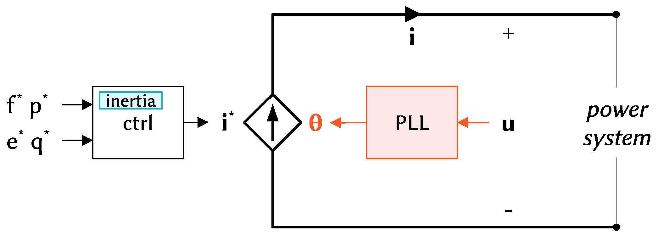
24]. The grid-following control employs a voltage-based synchronisation control, requiring the grid voltage at its terminal (
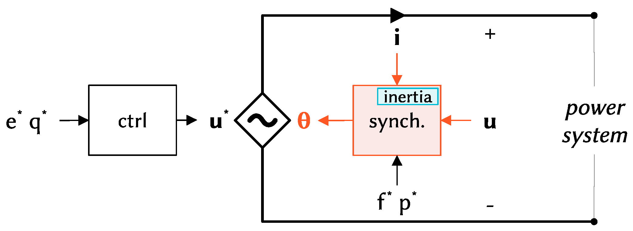
Figure 1). The grid-forming control is based instead on a power-based synchronisation control, providing the grid voltage at its terminal (
Figure 2). A grid-following converter can therefore be regarded as a voltage-based oscillator, while a grid-forming converter is fundamentally a power-based oscillator. In terms of inertia effect and support to the frequency control of the system, both grid-following and grid-forming can provide the corresponding functionalities. However, how a given functionality is realised can make a significant difference for the system. Different implementations of the inertia effect might have completely different impacts on the oscillatory characteristics of the system. This is indeed the case of grid-following and grid-forming control with inertia capabilities. Grid-following can provide inertia to the system with the inclusion of outer loops into the control of the converter (
Figure 1). Grid-forming instead implements an intrinsic inertia effect, directly included in the synchronisation control loop of the converter (
Figure 2). Due to this substantial difference in the realisation of the inertia capability, grid-following and grid-forming converters are expected to have a completely different impact on the oscillatory characteristics of the system. In particular, grid-following implements synthetic inertia with additional outer loops in the control system, without a direct engagement of the synchronisation unit, the phase-locked loop (PLL). Grid-forming instead realises the intrinsic inertia capability directly in the synchronisation unit, involving active power for both synchronisation and the inertia effect. When power-frequency oscillations occur in the system, grid-following with inertial capabilities will participate in the oscillations only marginally, because the unit-determining frequency and angle of the converter is not directly affected by the synthetic inertia control. On the other hand, grid-forming will be significantly engaged in the power-frequency oscillations of the system, because power is directly involved in the unit that is responsible for determining the frequency and angle of the converter. The discussion about the different impact on the system oscillations of grid-following and grid-forming converters can be related to the converse swing characteristics presented by the two control structures. The grid-following control is in fact characterised by a voltage-angle swing, while the grid-forming control is characterised by an active power-angle swing [
21]. It is then straightforward to expect a particular impact of the two control structures on the oscillations of the system, which are predominantly determined by the active power-angle relationships, as known.
The underlying reason for the different oscillatory characteristics expected from grid-following and grid-forming controls can be also illustrated in terms of the delay effect related to the inertia capabilities of the power converter. The inertial effect can ultimately be regarded as an intentional delay in the reaction to a power-frequency transient [
25,
26,
27]. When this delay is added directly within the synchronisation unit, as in the grid-forming control, the converter has a reduction of the damping capabilities, introducing more oscillations into the system. When, instead, the synchronisation control is not affected by the delay related to the inertial effect, as in the grid-following with synthetic inertia, the converter participates less in the oscillations of the system, offering better damping capabilities.
It is essential to acknowledge that different implementations of the converter control scheme can indeed modify the oscillatory characteristics offered by the given control scheme, such as, for instance, the addition of transient damping terms [
28,
29], the implementation of inertial effect and fast frequency response directly with the PLL [
30], or the application of lead-lag filters and phase compensation in the synchronisation loop [
31,
32,
33]. The considerations about the expected different impacts of grid-following and grid-forming converters on the oscillatory characteristics of the system remain valid, however, since they refer to fundamental traits of grid-following and grid-forming common to the different control schemes. These aspects are further investigated in the next section considering the overall point of view of the system for closed-loop dynamics, with comprehensive modal analysis and time-domain simulations. It is worth specifying that the comparison between grid-following with synthetic inertia and grid-forming will be done in all cases under the assumption of the same inertial capabilities offered by the two control strategies. Some further considerations regarding the conditions of this equivalence can be found in [
13]. Since the inertia is acknowledged as a fundamental factor affecting the oscillatory characteristics of the system, the equivalence in the inertial capabilities is assumed in this work as a fair basis for the investigations of the impact of the considered controls on the power-frequency oscillations.
3. Electromechanical Oscillations in Converter-Dominated Power Systems
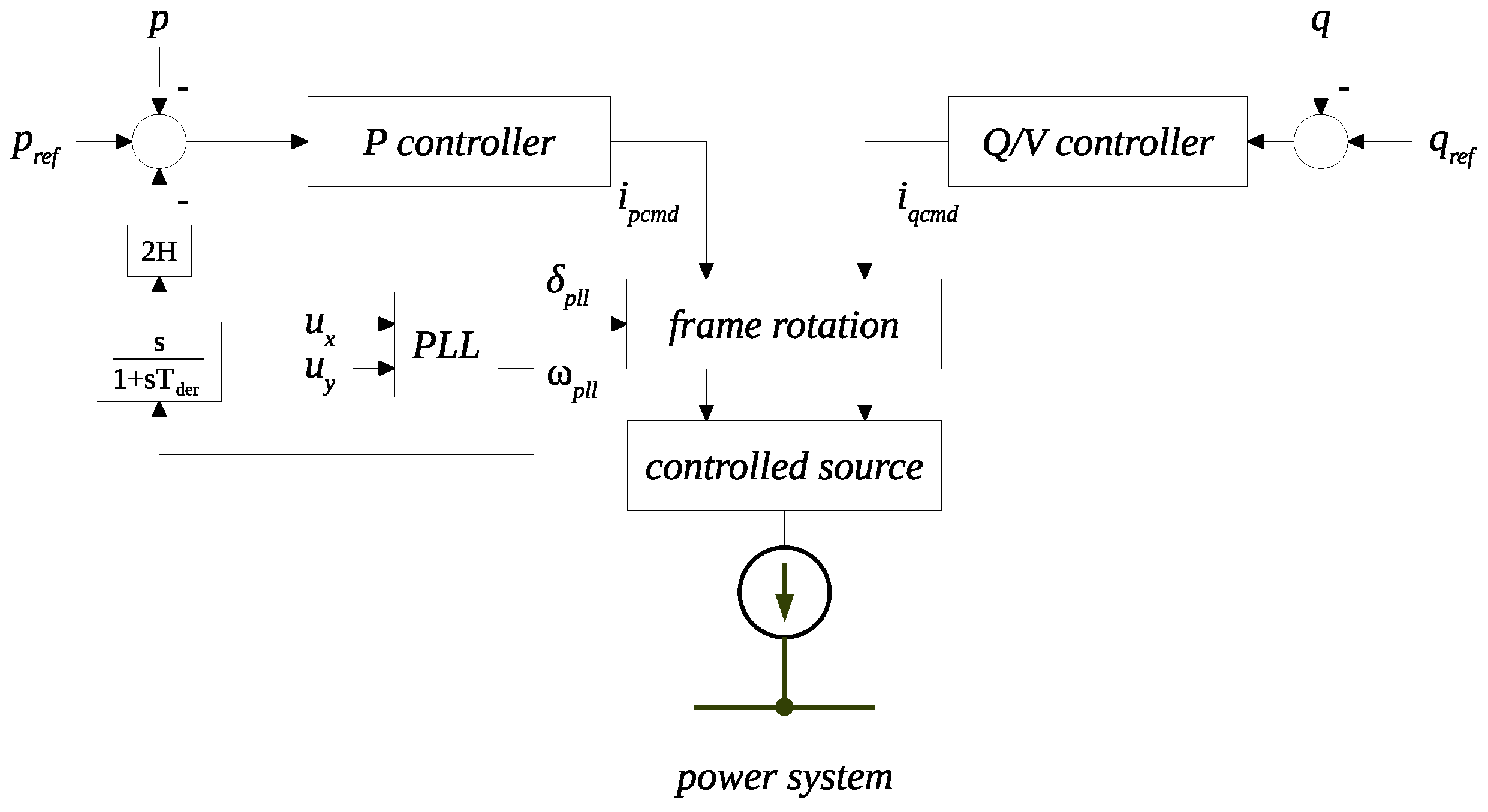
The investigation of low-frequency electromechanical oscillations in converter-dominated power systems is performed with reference to grid-following with synthetic inertia and grid-forming control schemes. The two control structures are considered for integration in the power systems under examination. The block diagrams of the grid-following and grid-forming controls are shown in
Figure 3 and
Figure 4, respectively.
Grid-following implements a conventional current vector control, with the possibility of activating a derivative-based synthetic inertia functionality. For phasor simulations, the element is represented as a complex controlled current source. The model of the grid-following converter for RMS phasor simulations is described by the following set of differential-algebraic equations:
The synchronisation through PLL is implemented with (
3), (
4), (
6), and (
7), where
and
are inputs to the PLL, and they represent the real and imaginary parts of the terminal voltage in the coordinate frame of the system. The voltage
is the imaginary part of the voltage in the local coordinate frame of the converter, and it is obtained by complex rotation of the terminal voltage using the angle
, provided by the PLL. The active and reactive power controllers are described by (
1), (
2), (
11), and (
12), and they implement proportional-integral controls. In the case of the active power controller, the reference power
is given by (
10), including the additional synthetic inertia control. The derivative-based control is modelled with (
5), (
8), and (
9), adopting a filtered derivative implementation. The synthetic inertia control then takes as input the frequency derivative
, computed from the filtered frequency
provided by the PLL. The variables with dot notation
,
,
,
, and
, represent the state variables of the integrators. The command currents
and
, respectively, provided by active and reactive power control, are then transformed from the reference frame of the converter into the coordinate frame of the system. For the transformations, the synchronizing angle
, provided by the PLL, is used. The currents
and
of the controlled source are thus obtained, with (
13) and (
14). The model described by (
1)–(
15) corresponds to a conventional grid-following implementation, with the addition of synthetic inertia control. More details about this standard model can be found in [
34,
35], while the synthetic inertia is a derivative-based control [
36].
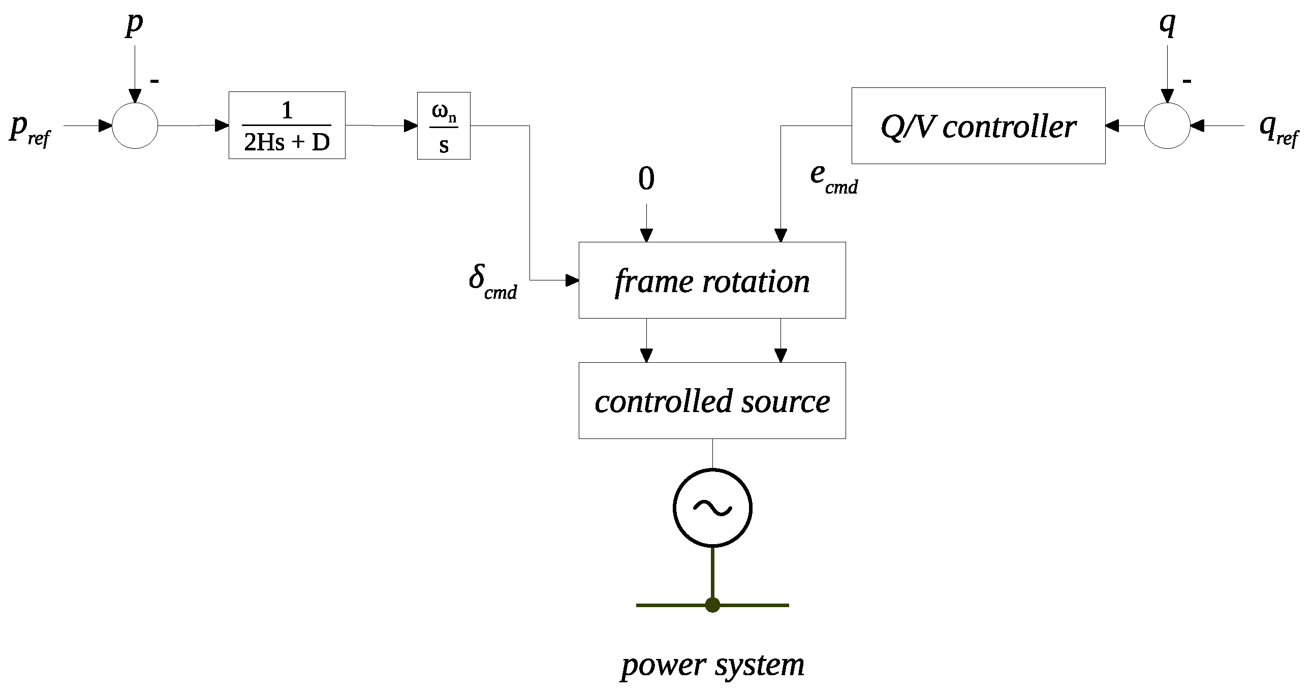
Grid-forming implements a common swing-based virtual synchronous machine instead, with the inherent provision of inertial capabilities within the synchronisation loop. For phasor simulations, the element is represented as a complex controlled voltage source. The model of the grid-forming converter for RMS phasor simulations is described by the following set of differential-algebraic equations:
The synchronisation is performed with a power-based mechanism that emulates the swing equation of synchronous machines, implemented with (
16) and (
17). The magnitude of the voltage is regulated with a proportional integral controller, described by (
18) and (
19). The angle provided by the active power control
is in this case the synchronizing angle. The angle
is obtained by integrating the frequency deviation
multiplied by the nominal angular frequency
. The frequency deviation is calculated by the emulation of the swing equation of synchronous machines, integrating the mismatch between reference and measured active power, considering the friction damping term
and dividing by the time constant
. The variables with dot notation
,
, and
also represent the state variables of the integrators in this case. The command magnitude
and command angle
of the voltage are then used for the transformations from the reference frame of the converter into the coordinate frame of the system. The voltages
and
of the controlled source are thus obtained, with (
20) and (
21). The model described by (
16)–(
22) corresponds to a swing-based grid-forming implementation, basically emulating the swing equation of synchronous machines [
37]. More details about this standard model can be found in [
38,
39].
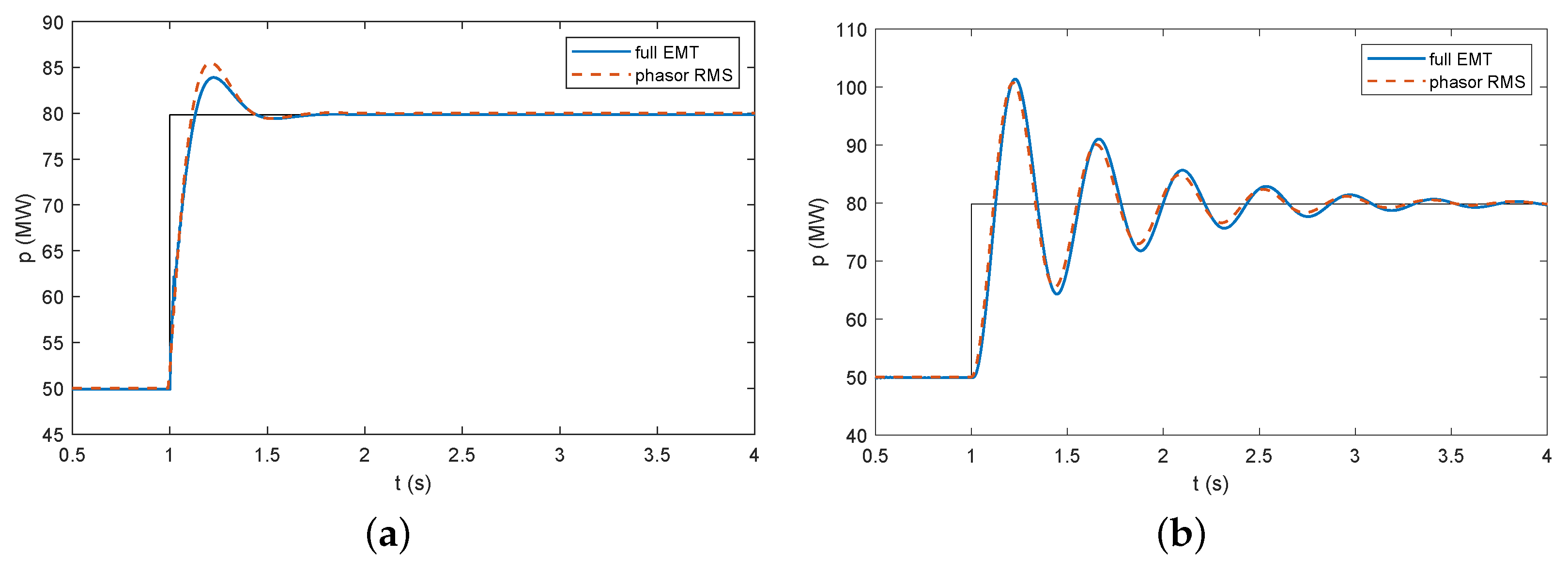
The models introduced above do not represent the DC side of the converter, and they do not include fast inner control loops for current and voltage regulation. These assumptions are verified comparing the phasor RMS models with full detailed EMT models. For both domains, the models are implemented in the Simscape Electrical toolbox of MATLAB/Simulink [
40]. The RMS models essentially implement the equations described before, while the EMT models; implementation includes inner control loops for current and voltage regulation, both for grid-following and grid-forming controls. In the EMT models, only the switching of the electronic devices is neglected, and an average model is considered for the power converter. The models are simulated for a step change in the active power reference of the converter (
Figure 5). The results indicate that the assumptions of neglecting DC side dynamics and inner control loops do not have a significant impact on the frequency dynamics or, generally, on the slow transients of the system [
41], which are the scope of this work. Therefore, these assumptions are assumed in the following analysis. Besides confirming the negligible impact of inner control loops on the dynamic phenomena under examination, the results of the simulations provided before also serve as validation of the RMS models that are used in the work.
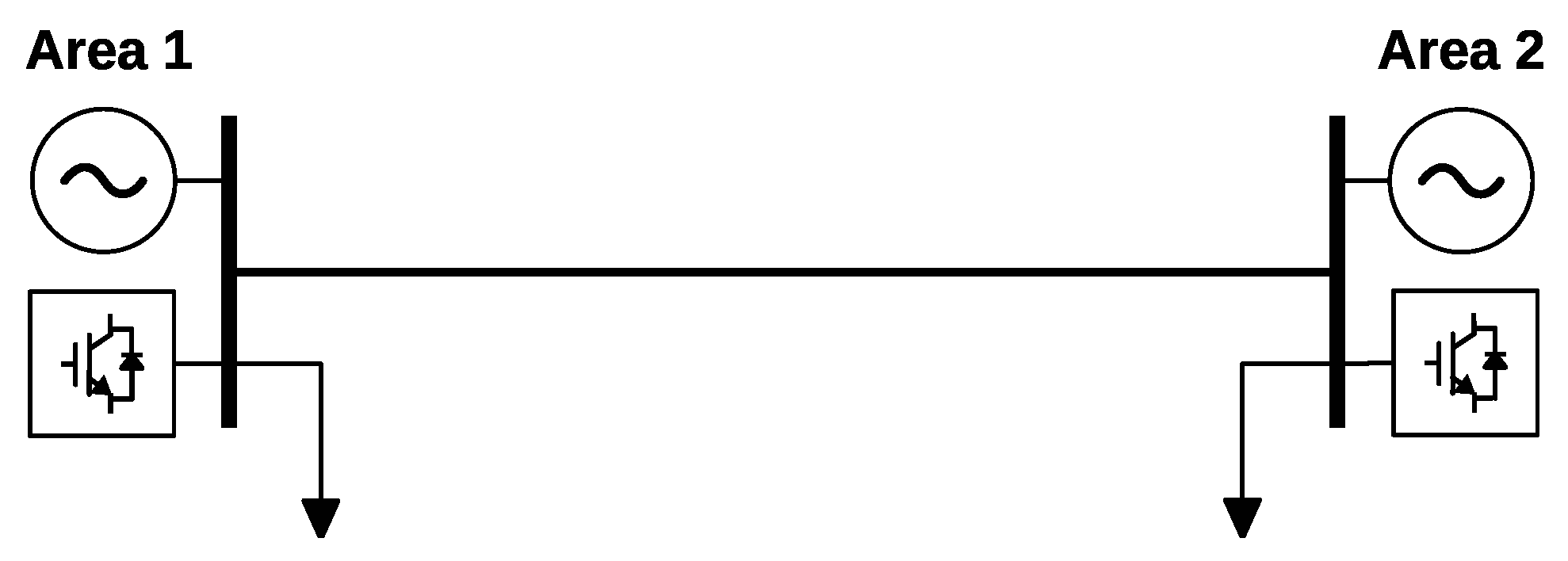
The investigation of low-frequency electromechanical oscillations in converter-dominated power systems is performed using the generic two-area network shown in
Figure 6. For the sake of comparison, the two areas have the same strength, kinetic energy, and primary reserve. The integration of a high share of non-synchronous generation in both areas is assumed. The integrated power converters can be regarded as an aggregation of several converter modules, which can be done according to the methodology detailed in [
42,
43]. The control system of the power converter can implement either the grid-following or the grid-forming control schemes described above.
The simulations are performed using the power systems analysis software NEPLAN [
44]. Both control structures are implemented in the overall mathematical model using custom-built dynamic models. The models of the grid-following and grid-forming converters shown in
Figure 3 and
Figure 4 are developed in SYMDEF (SYMbolic DEFinition), a proprietary modelling language of the software, and they are properly integrated into the initialisation procedure of the overall mathematical model by adding equation-based constraints for load-flow conditions. The fundamental parameters of the user-defined models are reported in
Table 1. All other parameters for the simulation of the converter-interfaced generation sources are taken from [
38,
45]. The parameters of the synchronous generation and the corresponding controllers for voltage and frequency regulations are instead taken from [
46]. The results of the simulations are post-processed using MATLAB [
40]. The handling of the whole process is done with the help of an external application that is written in C#. The application accesses the available APIs of NEPLAN, runs the simulations in an automatic fashion, and then calls MATLAB as COM automation server for the generation of the graphical outputs.
The reference system of
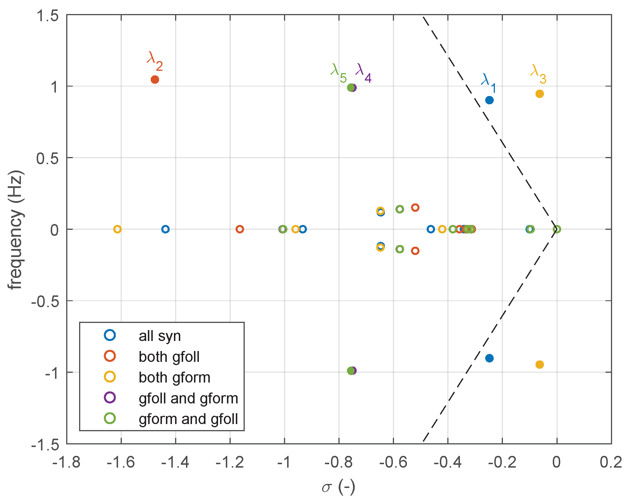
Figure 6 is first examined with a modal analysis. The small-signal stability module of the software is used to compute the eigenvalues of the full non-linear model of the system. The results for the different cases under investigation are reported in
Figure 7. The eigenvalues in the typical region of electromechanical oscillations (1 Hz) are marked with filled circles. The plot also shows a dashed line corresponding to a damping ratio of 5%.
It can be observed that, in the case of both areas with grid-following converters, there is one oscillation mode around 1 Hz, with a relatively big damping ratio (
). This denotes high damping properties of the system and very limited participation of the grid-following with synthetic inertia in the oscillatory characteristics of the power system. In the case of both areas with grid-forming converters, on the other hand, there is an oscillation mode around 1 Hz with rather low damping (
). This denotes a significant involvement of the grid-forming controls in the oscillatory behaviour of the system, and poorly damped oscillations are expected in the transient response to a perturbation. In the case of grid-following predominant in one area and grid-forming predominant in the other one, there is oscillation mode around 1 Hz (
or
). However, the damping is significant in this case, indicating an appropriate oscillatory behaviour of the system. An overview of the oscillation modes for the examined cases is reported in
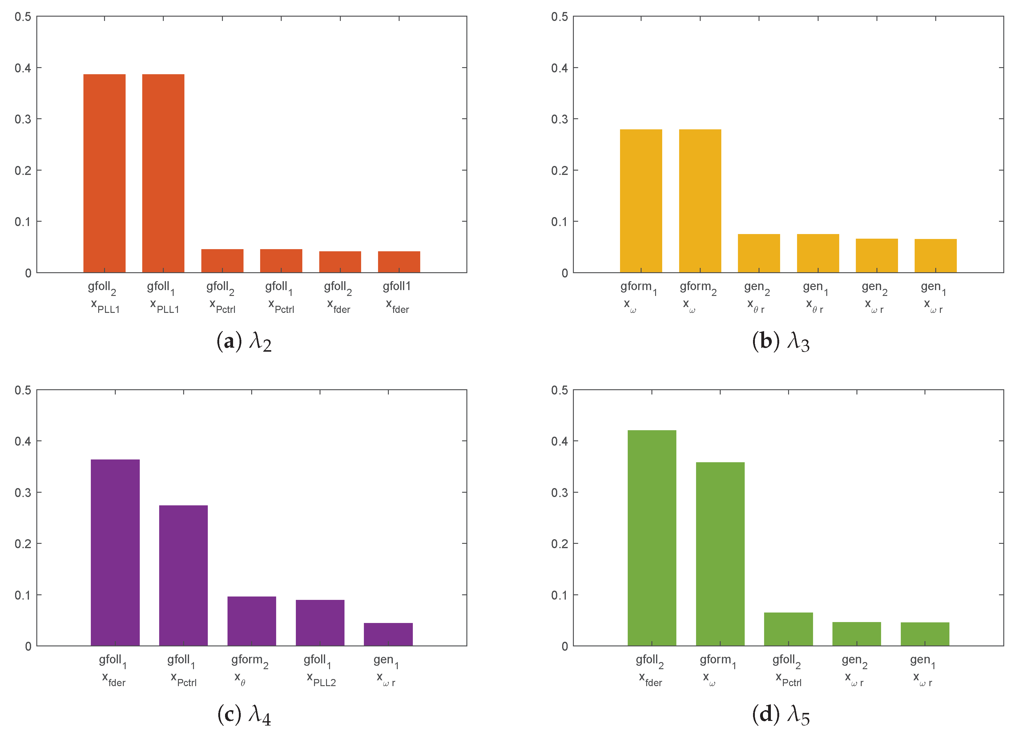
Table 2. The computed participation factors with the most participating state variables are shown in
Figure 8.
The participation factors that are shown in
Figure 8 clearly indicate the elements involved in the electromechanical oscillations of the system. In the case of grid-following converters in both areas, the most participating state variables are the states of the first integrator of the PLL (
Figure 8a). In the case of grid-forming converters in both areas, the state variables participating in the oscillation mode are the states of the second integrator of the synchronisation loop (
Figure 8b). When, instead, grid-following converters are dominant in one area, and grid-forming converters are dominant in the other one, the variables participating in the oscillation mode are the states of the PLL and the synthetic inertia control for the grid-following converters and the states of the synchronisation loop for the grid-forming converters.
The reference system of
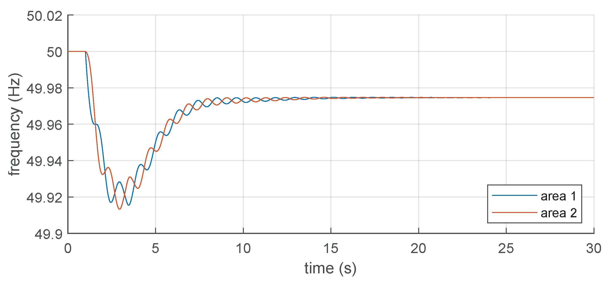
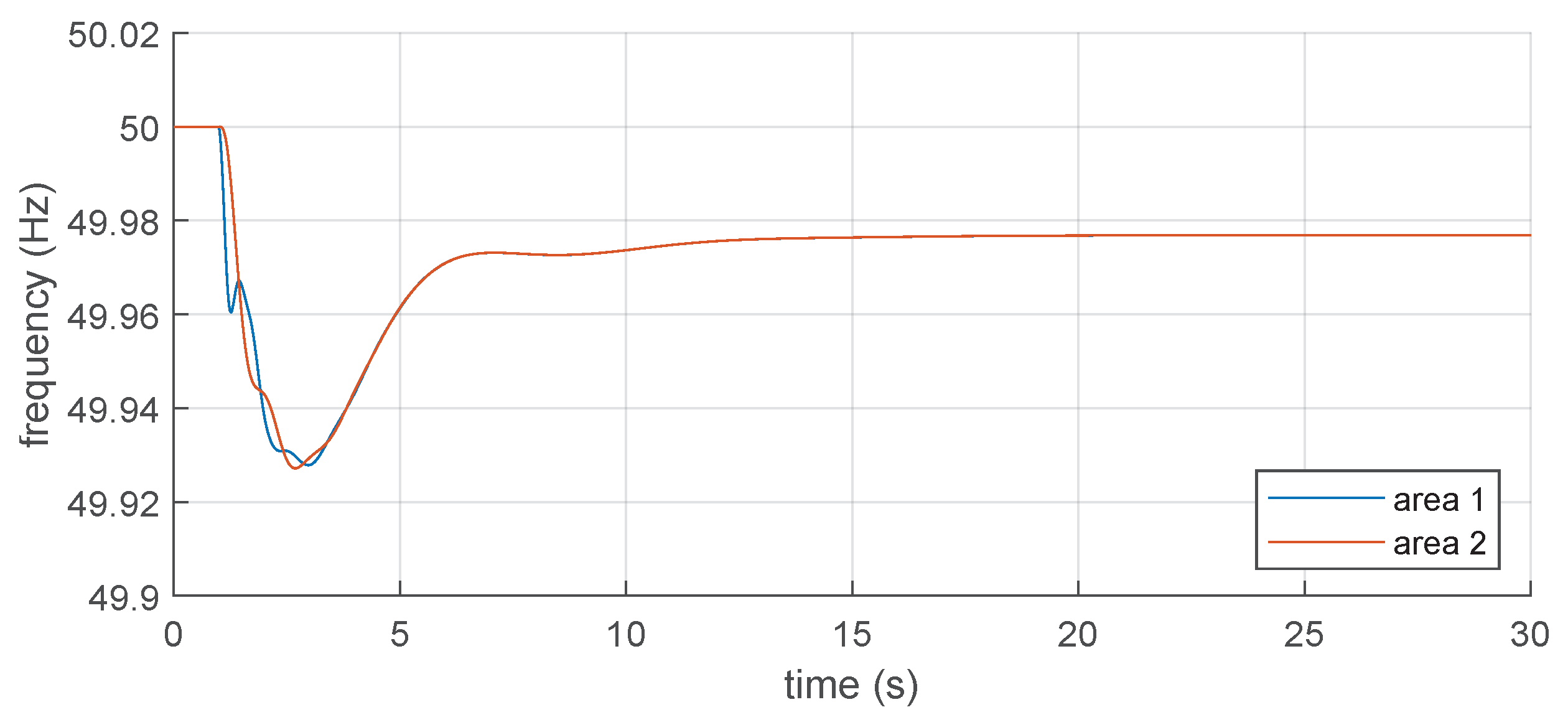
Figure 6 is then examined with time-domain phasor simulations, using the RMS dynamic analysis module of the software. The system is simulated considering a sudden power imbalance
P in Area 1. The results of the dynamic simulations are shown in
Figure 9,
Figure 10,
Figure 11,
Figure 12 and
Figure 13.
It is possible to observe that the impact of the grid-following control with synthetic inertia functionality on the oscillations of the system is almost null (
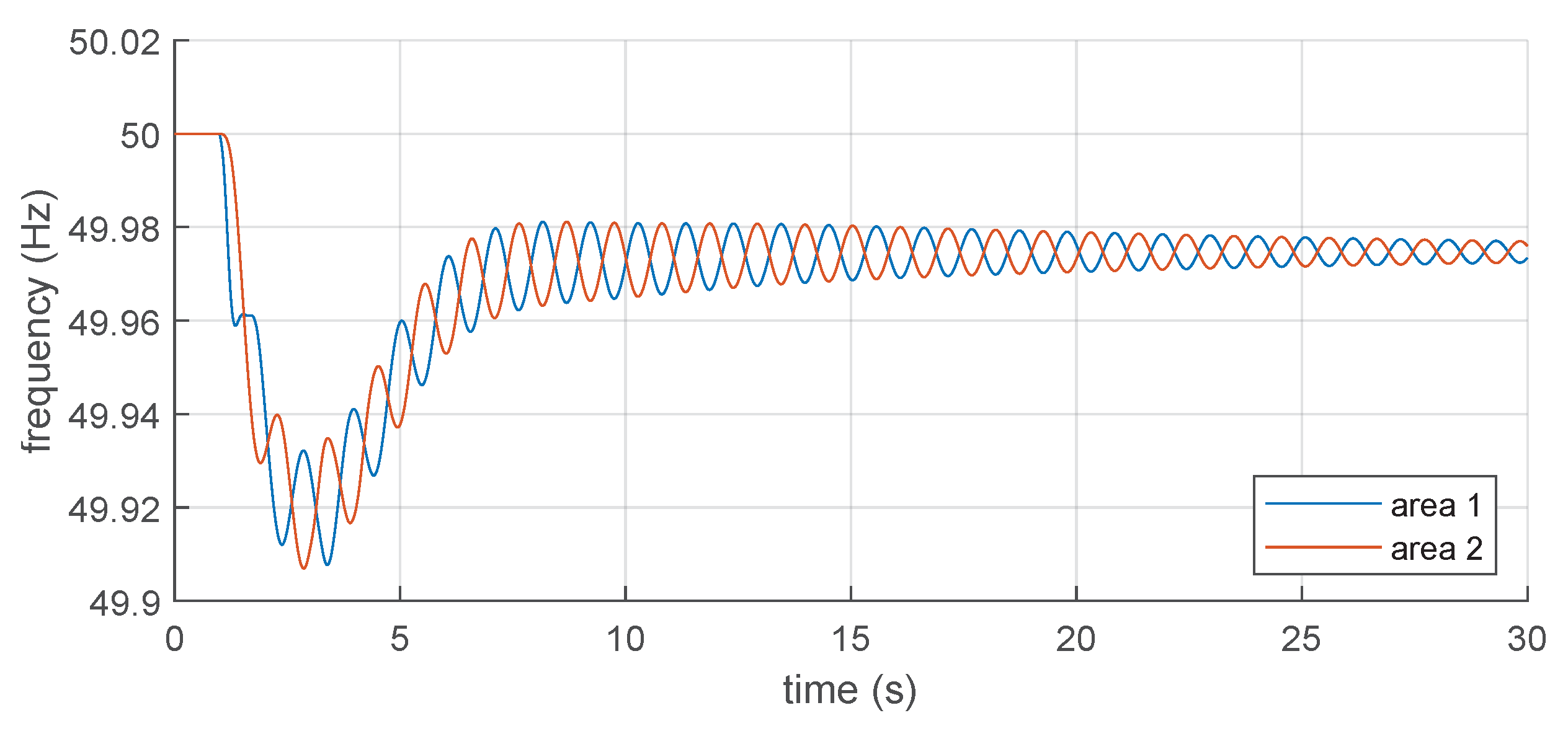
Figure 10), and there are basically no swings in the power-frequency transient. The impact of the grid-forming control on the oscillatory behaviour of the systems is instead significantly more critical (
Figure 11), with the introduction of sustained oscillations in the power-frequency transient. If grid-following is dominant in one area and grid-forming is dominant in the other one, there are some swings between the two areas after the power imbalance (
Figure 12 and
Figure 13), but they are quickly damped in the very first instants of the transient. Small differences between the two cases can be due to the location of the disturbance and different loading conditions.
4. Case Study: The Colombian Interconnected National System
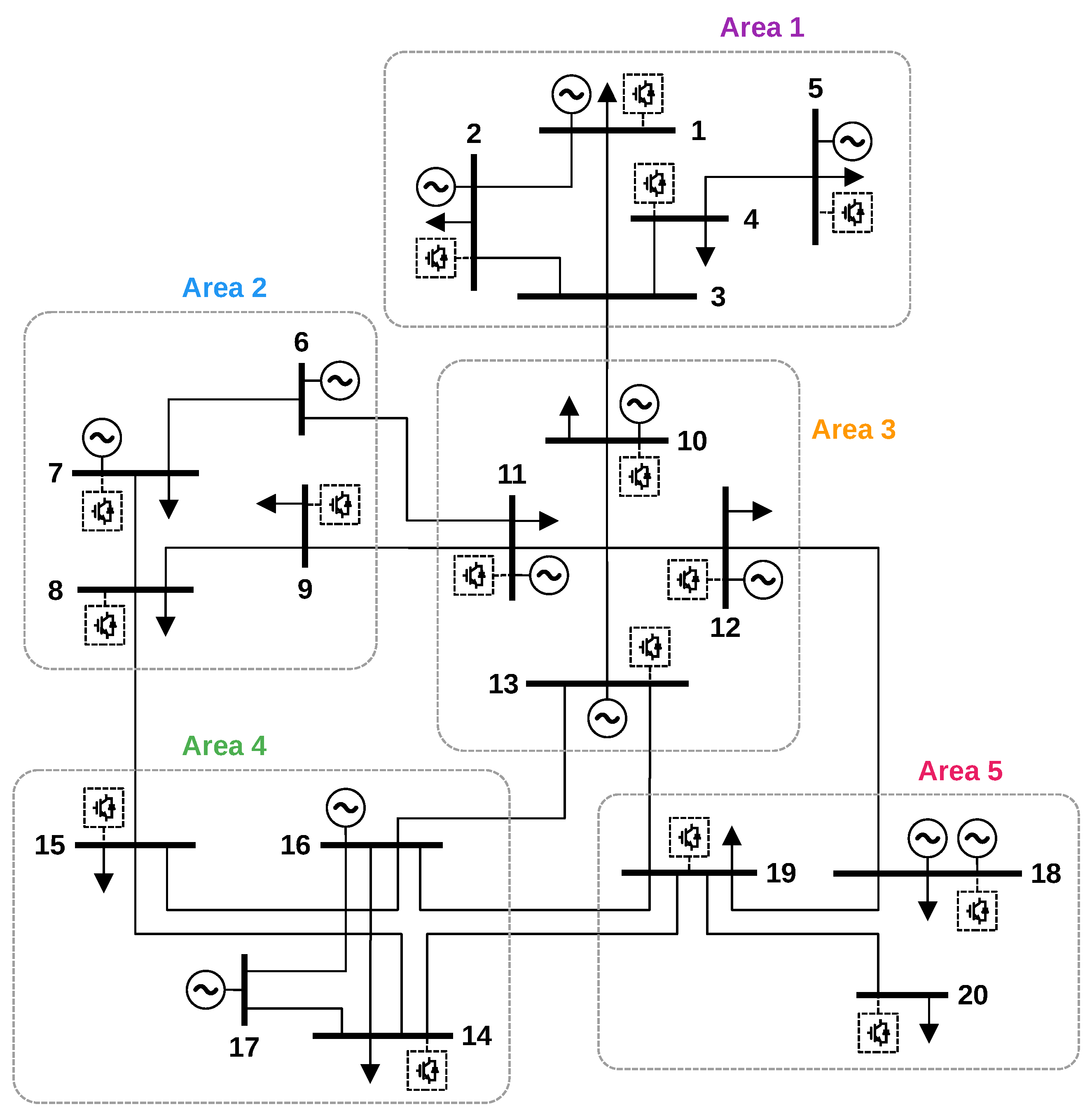
The considerations regarding the impact of different types of non-synchronous generation on the electromechanical oscillations of the system are applied with a case study of the Colombian power system. The National Interconnected System (SIN) is studied here with a simplified network including 20 buses and 13 generators (
Figure 14). Data and configurations of the simplified system are provided in [
47]. The Colombian system is basically divided into five areas. Area 1 is the north of the country, up to a substation called Sabanalarga with voltage levels 500/230 kV. Area 2 is Antioquia, with the San Carlos power plant. In this region, there is a significant amount of hydro generation, since it is a very mountainous area. A new big hydro power plant, Hidroituango, is currently (2022) under construction. Area 3 is the north-east, the border with Venezuela. Here, the generation is predominantly thermal. Area 4 includes the departments of Valle del Cauca and Cauca. In this region, the generation is both thermal and hydro. Area 5 is the south of the country, Nariño Putumayo, the border with Ecuador. Regarding the integration of renewable energy sources, wind generation is mainly concentrated in Area 1, while solar generation is distributed across all areas of the country.
Historically, the electricity demand of the country has been supplied by hydro and thermal generation, with approximately 65% and 35% contributions, respectively [
48]. The Colombian power system is heavily dependent on hydro power plants, and this makes it highly vulnerable to droughts. Given the availability of natural resources, power plants are situated in the north-west and central regions of the country. Some natural resources are also located in the departments of Valle del Cauca and Cauca, playing an important role for the country. However, Colombia also has other abundant renewable energy resources, such as solar and wind, which remain largely unexploited [
49]. The increase of the electricity demand could therefore be satisfied by these resources for a green transition of the Colombian system. The expected trend is, in fact, a significant increase of the generation from variable solar and wind resources [
50,
51]. This will cause a corresponding increase in power electronics in the system. The massive integration of converter-based generation is indeed a main aspect marking the ongoing energy transition in Colombia [
52], and it will have a significant impact on the operation of the system. In scenarios with high penetration of non-synchronous generation, recent studies show that there is a need for synthetic inertia provided by power converters, to avoid the activation of under-frequency load-shedding schemes [
53].
The Colombian system is, therefore, an appropriate case study for the purposes of the article. The location and availability of energy sources in few regions with limited demand poses a strong requirement in terms of the transmission grid, with power transported over long distances to reach the regions where the demand is concentrated. This peculiar aspect makes the Colombian system exposed to power-frequency oscillations in case of incidents. At the same time, the exploitation of available renewable energy sources such as solar and wind will require a significant integration of power converters in the system, with a consequent impact on the oscillatory characteristics and the possibility of implementing different control strategies. The Colombian system is studied with a model of the simplified SIN network, developed and implemented in the software NEPLAN [
44]. The basic scenario is compared with a future scenario characterised by a reduction of synchronous generation, with wind and solar accounting for 50% of the total demand of the country. According to the development plans, these renewable sources are expected to be distributed all across the country. However, wind sources are mainly located in the north (Area 1), while solar power plants are present in all areas. This is reflected in the consideration of all integrated sources as solar plants, except the source connected to node 4, which represents instead a wind plant. The locations of the non-synchronous generation sources in the simulation model are indicated in
Figure 14 with dashed boxes. When these sources are connected to the system, a corresponding amount of synchronous generation is disconnected. The representation of the non-synchronous generation is done with the same methodology as in the analytical section. The control system of the power converter can implement either the grid-following or the grid-forming control scheme described previously in the article. The dynamic models of both control structures are developed as custom-built elements and included in the overall mathematical model of the system built by the software. The analysis is again performed in two parts, modal analysis and time-domain simulations. The main parameters of the simulated dynamic model of the Colombian system are reported in
Table 3. The basic parameters of grid-following and grid-forming controls are the same as in
Table 1, so they are not repeated here.
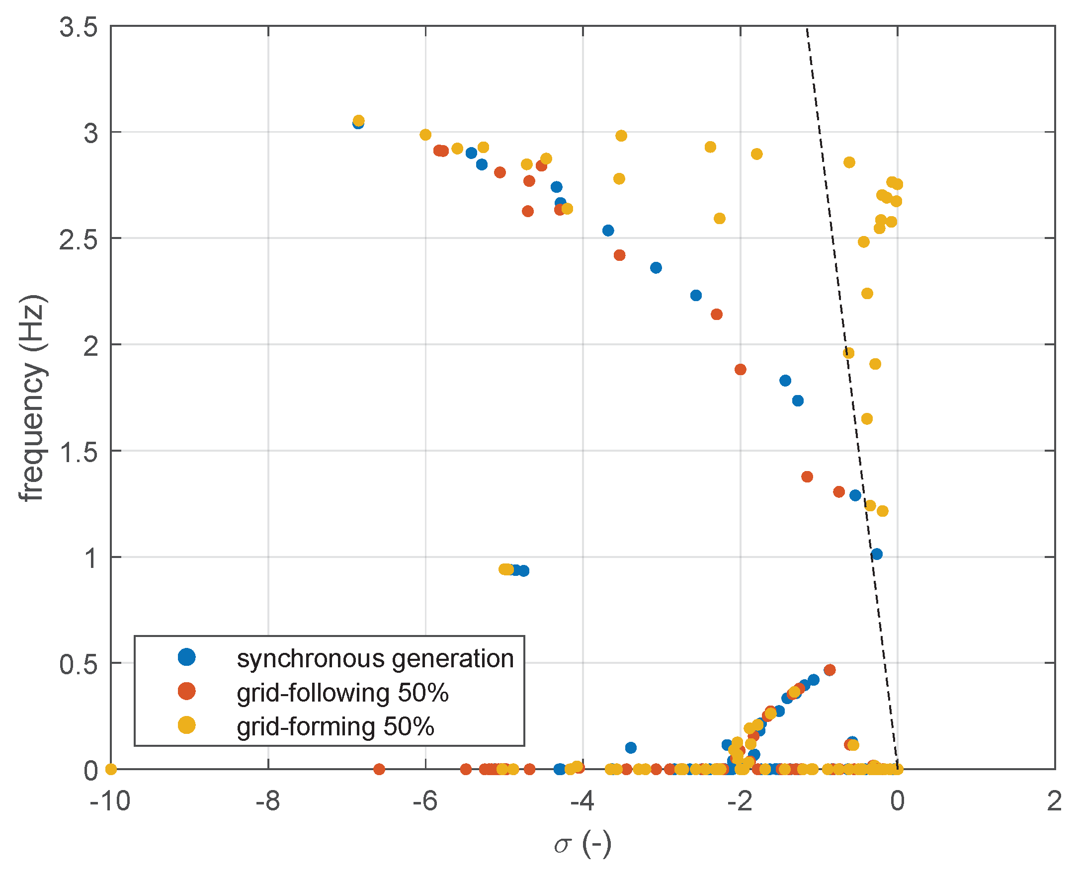
The results of the modal analysis are shown in
Figure 15. It is possible to observe that with 50% integration of grid-following power converters with synthetic inertia control, the oscillation modes of the system shift towards higher values of damping and slightly higher oscillation frequencies (orange circles in
Figure 15). In this case, the analysis indicates that the Colombian system can integrate a large number of grid-following generation sources and at the same time preserve adequate oscillatory characteristics, even when the grid-following converters are required to provide synthetic inertia to the system. When, instead, the system is modified with 50% integration of grid-forming power converters, the oscillatory properties of the system can significantly deteriorate, with a critical reduction of the overall damping (yellow circles in
Figure 15). The analysis indicates that the Colombian system cannot integrate a large number of grid-forming generation sources without jeopardising the oscillatory characteristics at different frequency ranges, in terms of both local and inter-area oscillation modes. The system might be, in this case, dangerously close to oscillatory instability, and the design of the converters controls should be carefully reconsidered.
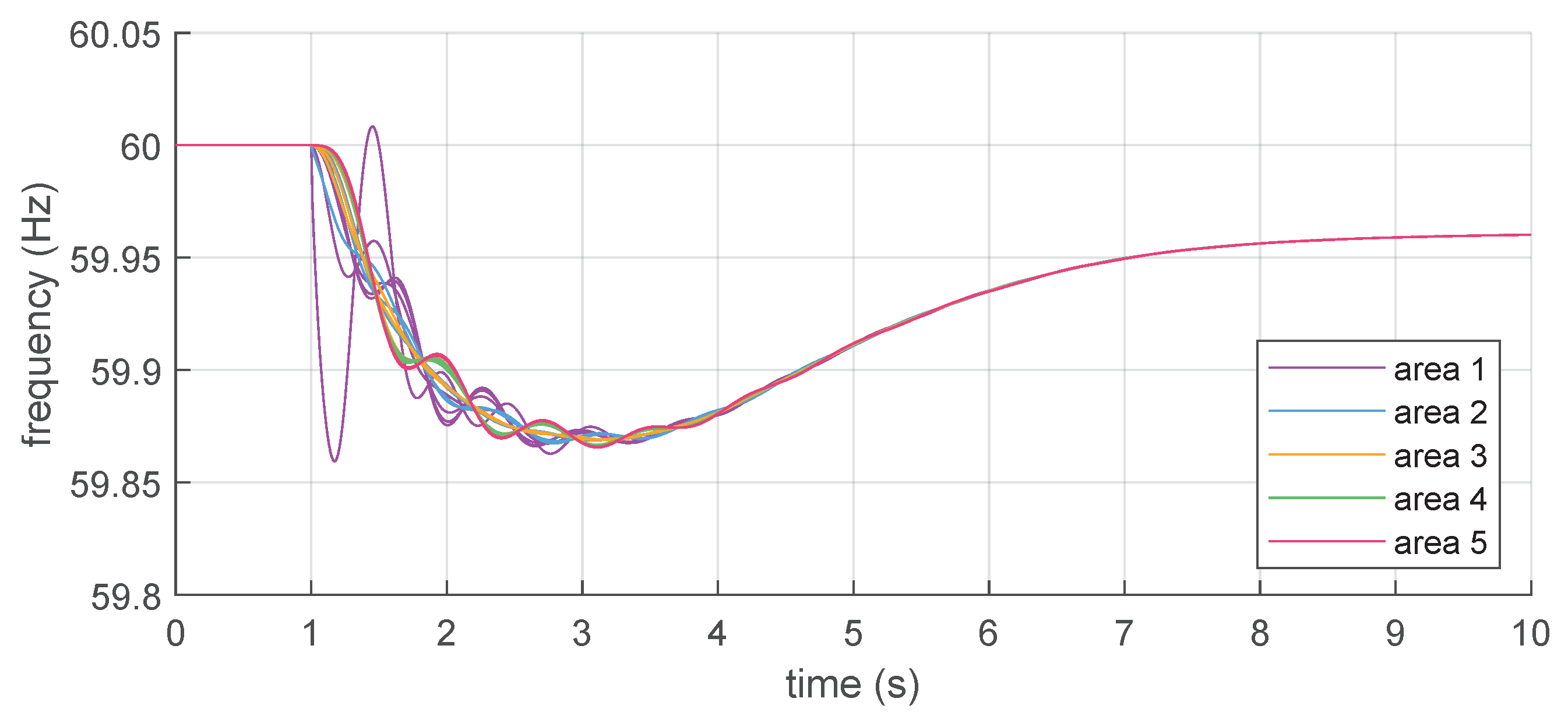
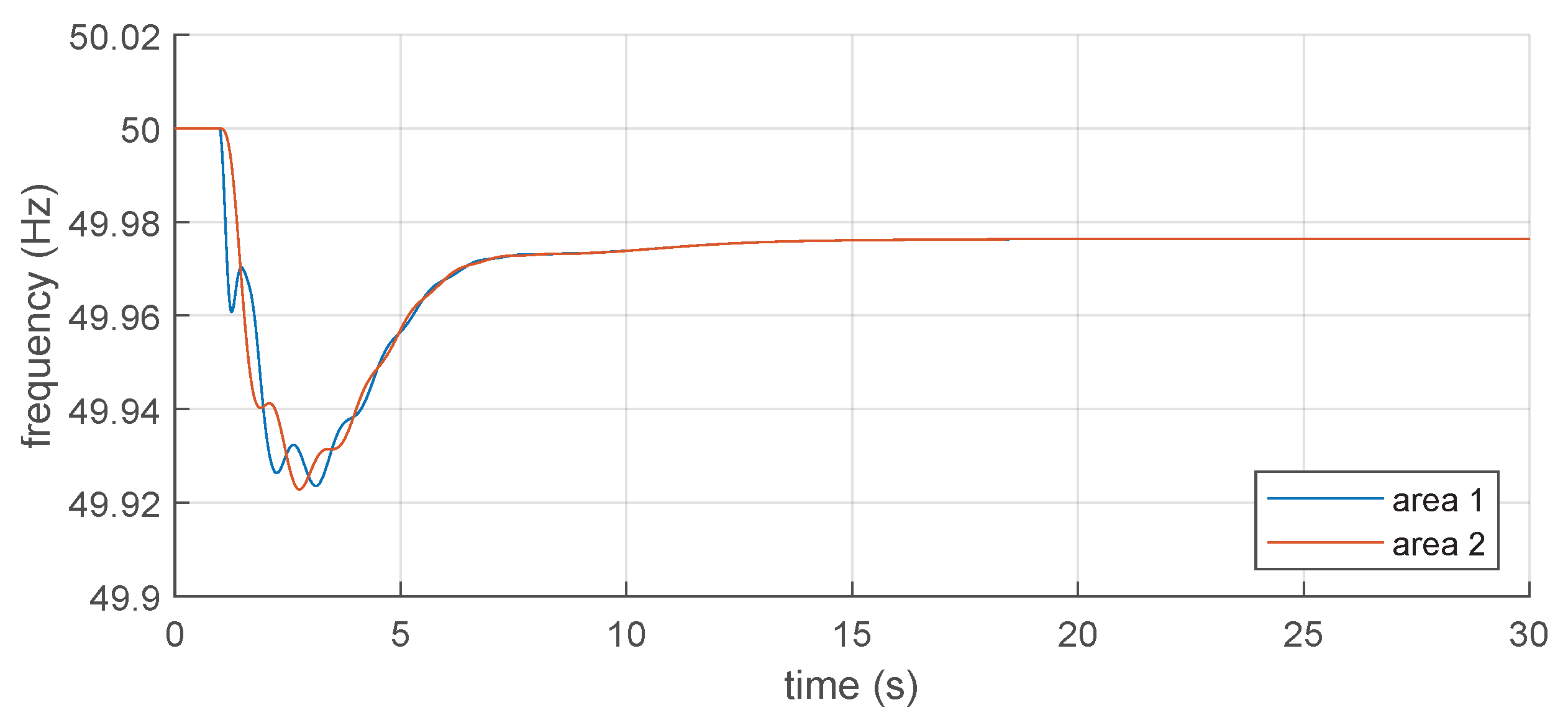
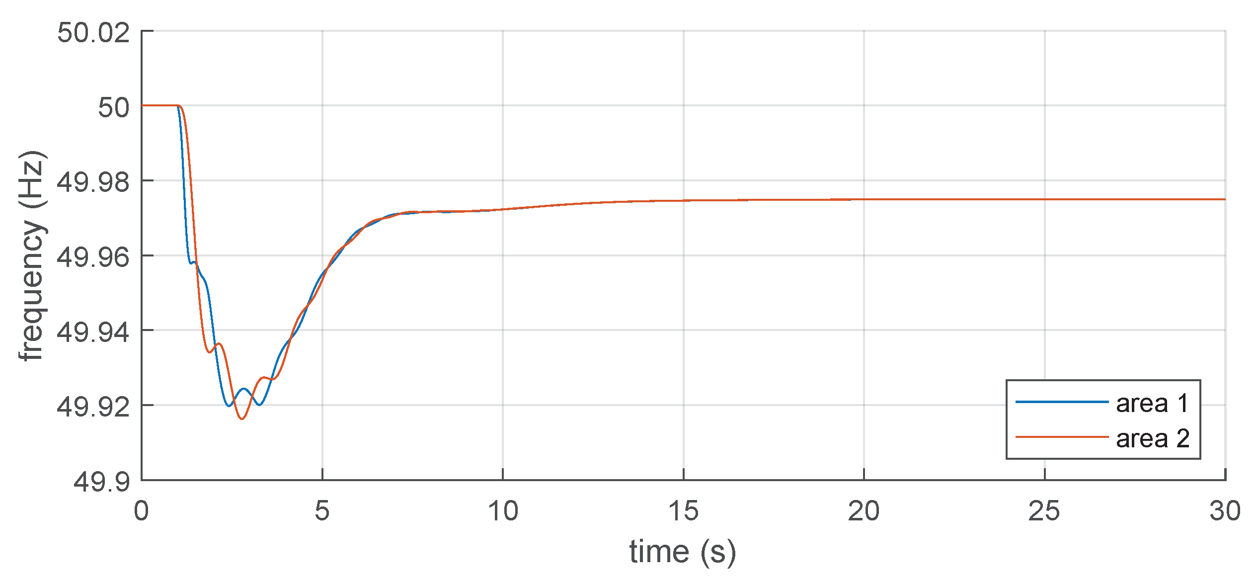
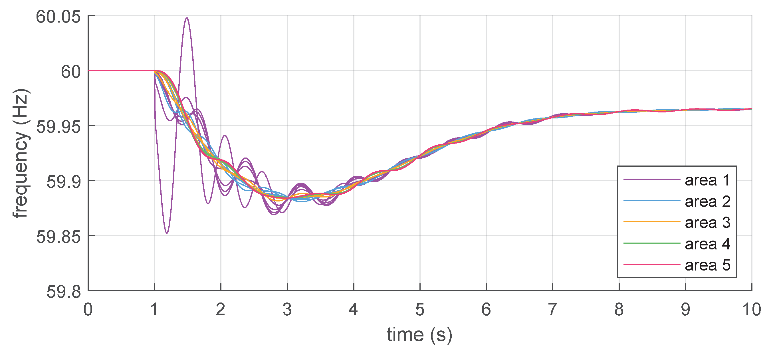
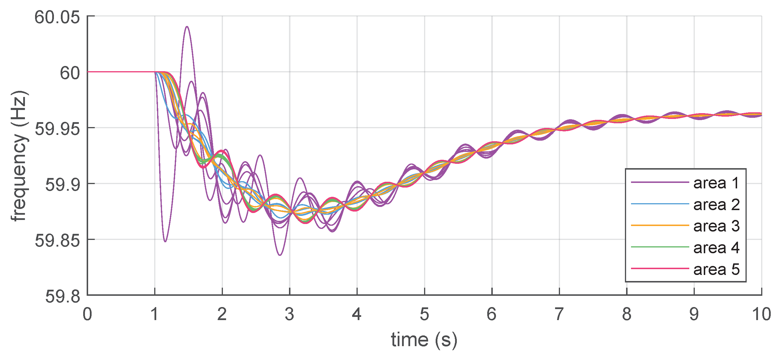
The Colombian system is next analysed with time-domain phasor simulations. The system is simulated for a sudden generation outage in Area 1. The results of the dynamic simulations are shown in
Figure 16,
Figure 17 and
Figure 18. For the considered disturbance, it is possible to observe that the system experiences both local and inter-area oscillations. The nodes closest to the location of the disturbance are significantly affected, with a severe rate of change of frequency and instantaneous frequency deviations, as expected. The system reaches a new steady-state condition after a series of transient power exchanges between generation sources. In the case of 50% grid-following with synthetic inertia, the system shows improved damping capabilities, with limited oscillations during the transient, and also a better coherency between the different areas. In comparison with the reference case of all synchronous generation, it can be noticed that the integration of grid-following generation sources reduces both the power-frequency swings related to local modes and the oscillations associated to the inter-area modes of the system (
Figure 17), even if the power converters are delivering synthetic inertia. The impact on the oscillatory behaviour of the system is therefore beneficial. In the case of 50% grid-forming, the dynamic behaviour of the system is instead clearly affected by prolonged oscillations in the low-frequency region, associated with an intense exchange of active power between the generation sources during the transient. In this case, the integration of grid-forming generation sources determines an increase of the power-frequency swings in the system, especially from the point of view of the inter-area modes (
Figure 18). In comparison with the reference case of all synchronous generation, the oscillations following the power imbalance actually increased, and a poorer coherency between the different areas is observed. The impact on the oscillatory characteristics of the system can therefore be adverse.
The results of the time-simulation agree, therefore, with the considerations derived from the modal analysis. The case study provides an insight concerning power-frequency dynamics of the Colombian power system in different scenarios, basically confirming the expected impact of non-synchronous generation on the electromechanical oscillation of the system, as discussed in the analytical part of the article. It can be then observed that future power systems with a high prevalence of non-synchronous generation sources might experience a reduction of oscillatory stability, depending on the control strategy adopted for the power converters that interface with the non-synchronous sources. It has been also observed that the issues related to power-frequency oscillations can affect both the local and inter-area modes of the system. Proper assessment of the control strategy of the non-synchronous generation sources is therefore necessary from an overall systemic point of view, especially when a grid-forming control is implemented [
4]. In this case, the damping characteristics of the chosen control strategy must be verified and enhanced with available solutions, if necessary, and control schemes that are capable of providing a positive contribution to the oscillatory characteristics of the power system should be preferred.


