Review

A Review of AC and DC Collection Grids for Offshore Renewable Energy with a Qualitative Evaluation for Marine Energy Resources

Department of Electrical Engineering, Division of Electricity, Uppsala University, Box 65, 751 03 Uppsala, Sweden
*
Author to whom correspondence should be addressed.
Energies 2022, 15(16), 5816; https://doi.org/10.3390/en15165816
Submission received: 30 June 2022 / Revised: 5 August 2022 / Accepted: 8 August 2022 / Published: 10 August 2022
(This article belongs to the Section A3: Wind, Wave and Tidal Energy)

Abstract

:
Marine energy resources could be crucial in meeting the increased demand for clean electricity. To enable the use of marine energy resources, developing efficient and durable offshore electrical systems is vital. Currently, there are no large-scale commercial projects with marine energy resources, and the question of how to design such electrical systems is still not settled. A natural starting point in investigating this is to draw on experiences and research from offshore wind power. This article reviews different collection grid topologies and key components for AC and DC grid structures. The review covers aspects such as the type of components, operation and estimated costs of commercially available components. A DC collection grid can be especially suitable for offshore marine energy resources, since the transmission losses are expected to be lower, and the electrical components could possibly be made smaller. Therefore, five DC collection grid topologies are proposed and qualitatively evaluated for marine energy resources using submerged and non-submerged marine energy converters. The properties, advantages and disadvantages of the proposed topologies are discussed, and it is concluded that a suitable electrical system for a marine energy farm will most surely be based on a site-specific techno-economic analysis.

1. Introduction

The global demand for clean and sustainable electricity is growing. As a result, the proportion of renewable energy sources in the grid is increasing. However, the supply of clean electricity cannot keep up with the demand [1]. Marine energy resources, such as wave power and marine current power, can play a crucial role in increasing the level of clean energy in the grid [2]. A necessary requirement for accessing offshore energy resources is an effective and reliable electrical system. As of now, no large farms with either wave power or marine current power have been constructed, and the question of how the electrical system should be constructed for these technologies is still very much not settled.
A natural point to start investigating suitable electrical systems for marine energy resources is to draw on experiences from offshore wind power. How to construct the internal collection grid in a wind farm and how to transmit the power to the shore have been extensively investigated for offshore wind power [3,4,5]. It can be observed that, in early projects, such as Horns Rev in Denmark, both the internal grid in the farm and the transmission to the shore were constructed using AC [6]. However, in recently completed large wind farms located far from the shore, it has been necessary to use high-voltage DC for the transmission of power to the shore [7]. The internal grid in the farms is, however, still based on AC voltage.
The use of DC, not only for transmission to the shore, but also for the internal collection grid, has attracted increasing attention. For wind power, multiple studies have been carried out on the subject and various topologies have been proposed. A feasibility analysis in [8] proposed four different DC collection grid topologies and showed that they had comparable capital costs to conventional AC collection grids. In [9], a series DC collection grid comprising an AC/AC converter, a high-frequency (HF) transformer and a diode bridge rectifier was proposed. The topology was improved in [10,11] by comparing the losses and improving the efficiency by utilizing different power converters and increasing the operating frequency of the transformers. A review paper compared string, cluster and series DC collection topology with conventional AC for offshore wind [12]. Research regarding offshore DC collection grids has primarily been focused on offshore wind applications, and has not often been expanded to marine energy in general.
Although no large farms with marine energy converters have been constructed and the research on the subject is non-extensive, a report [13] has discussed various grid layouts for marine energy resources. In the report, it was noted that the traditional assumption in the design of electrical systems for marine energy resources entailed an analogous application of the technologies used in offshore wind. Therefore, the discussed topologies have often been based on AC collection and transmission, as in [14,15]. It was, however, also observed in [13] that a system solely based on medium-voltage DC for the internal collection of power in a farm and transmission of power to the shore could bring advantages regarding the size and cost of cables. Furthermore, since the use of DC technologies makes it possible to downsize components, it is of interest to study the possibility of using DC collection and DC transmission for marine energy resources.
Previous reviews in the field have focused on, for example, components for collection grids [16] or control strategies [17], whereas this article aims to review topologies of collection grids for marine energy. This article will give an overview of proposed AC and DC collection grids for offshore wind power and, given the possible benefits of DC collection grids, suggest and evaluate five different DC collection grid topologies for marine energy resources. The essential components of these systems will be discussed from different perspectives.

2. Scope of the Paper

The scope of this paper firstly extends to offer a broad review of the AC and DC collection grids proposed in the literature. This is provided in Section 4 and Section 5. These sections present the essential components, state-of-the-art technologies and the range of costs for some commercially available components and systems. Since an important factor in the choice of DC and AC technologies is the possible transmission distances for the technologies, this is investigated in Section 6. Finally, a qualitative evaluation of five different DC collection grid topologies for marine energy resources is presented in Section 7. The qualitative evaluation is limited to a focused discussion on issues such as costs and power losses and on highlighting the advantages and the disadvantages of the five topologies with regards to marine energy resources where the marine energy converter is either mounted directly on the seabed or placed on a platform or floating.

3. Marine Energy Resources

In this article, the term marine energy resource includes wave power and marine current power. The estimated potential of wave energy worldwide is 32 PWh/year [18]. The worldwide potential of marine current power has not been investigated to the same extent; however, one study [18] stated that the worldwide potential of marine current power is around 3 TW [18]. Only a fraction of this is, however, predicted to be utilizable with regards to the technical limitations of accessing the location of the marine currents. Even though the potential of marine energy worldwide is great, the installed generation capacity is only around 500 MW worldwide, of which tidal range generation constitutes about 99% [18].
There are various concepts for wave and marine current energy converters—see, for example, [19,20,21]. A complete discussion of the possible topologies of wave and marine current energy converters falls outside the scope of this article.

4. AC Collection Grids

AC collection grids are the commercial standard in offshore wind farm construction. However, there are no standard AC collection grids for wave or marine current power. By studying the topologies chosen for offshore wind farms, a great deal of knowledge and experience can be obtained to help in designing an AC grid for marine energy systems. In this section, an overview of AC collection grids from the perspective of offshore wind power will be presented.
The four most commonly proposed topologies of AC collection grids for offshore wind farms are the radial topology, the single-sided ring topology, the double-sided ring topology and the star topology [4,5,12,22,23,24]. Beyond these topologies, many different hybrid topologies or combinations of the four topologies have been proposed—see, for example, [5,25]. Other topologies can be found; however, they often share some characteristics or are, in fact, subcategories of the four topologies. Therefore, it should be sufficient to investigate these topologies to give an overview of AC collection grids.
The study of AC collection grids in this paper is focused on the main components of AC systems, such as cables, connectors and transformers. Since many of these components are commercially available, the presentation takes into account, among others, different available technologies and expected costs.

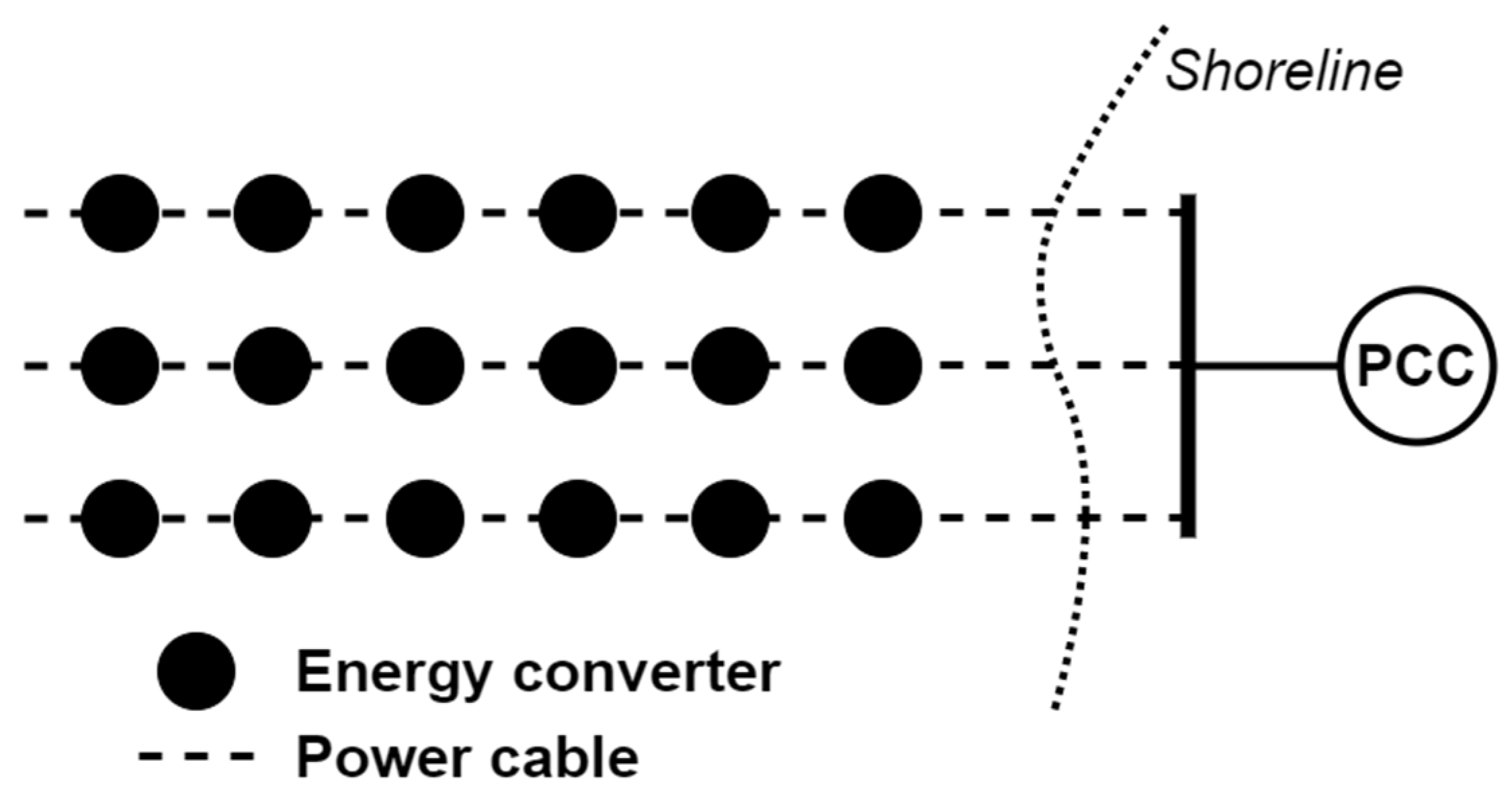
4.1. Radial Topology

In a radial topology, all energy converters in the offshore farm are connected to a single feeder cable. This system is illustrated in Figure 1, where three feeder cables are connected to a bus onshore, which, in turn, is connected to the external distribution system at the point of common coupling (PCC). The radial topology is one of the simplest and most widely used topologies [22]. However, the single cable means that there is no redundancy in case of faults. If a fault were to occur on the cable, all units upstream from the fault would be disconnected from the grid. The number of units that can be connected to one feeder cable is limited by the rating of the cable. The main advantages of the radial topology are that it is easy to control and that it requires less cable, while the main disadvantage is the poor reliability due to the lack of redundancy [23].

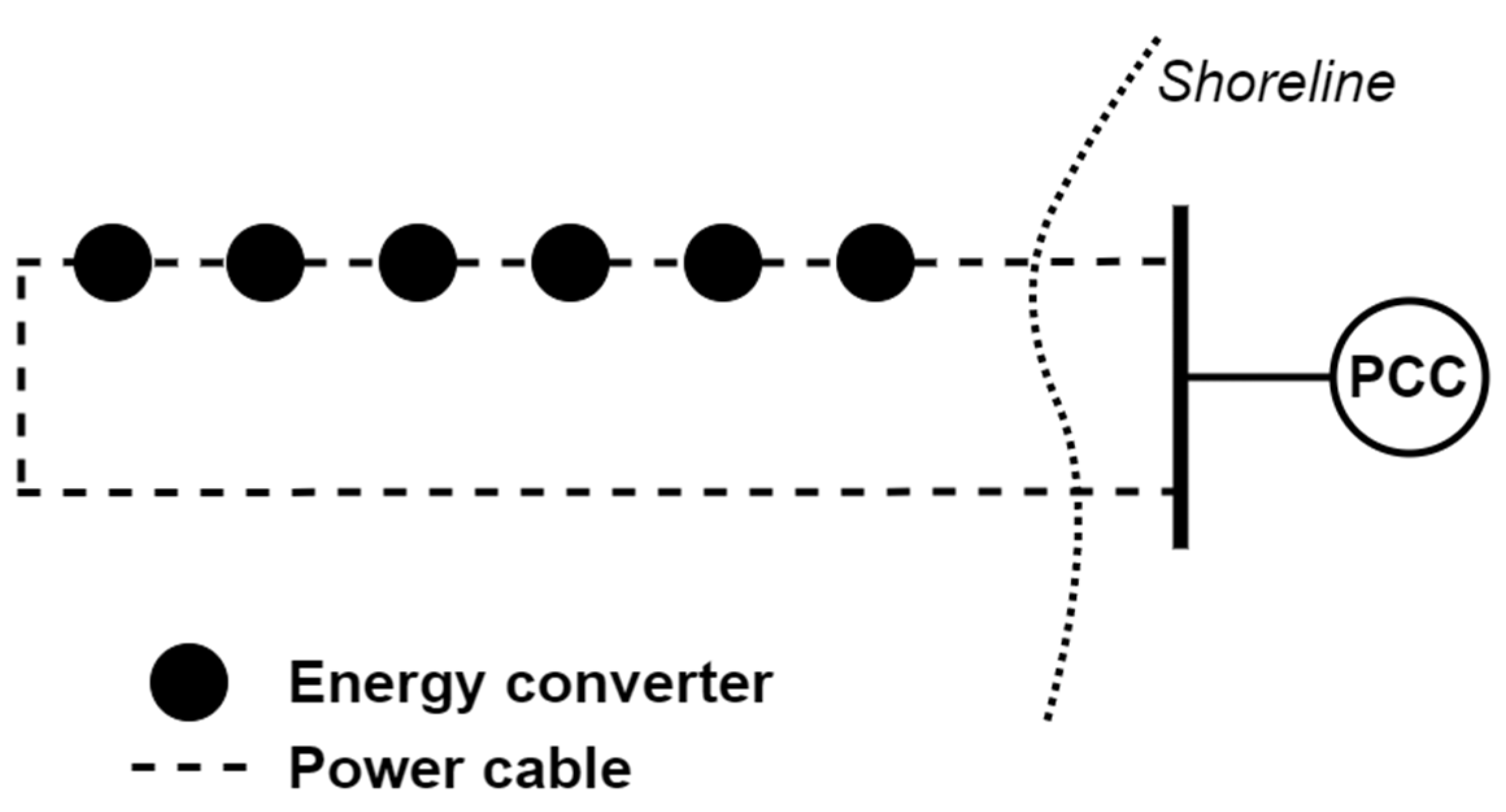
4.2. Single-Sided Ring Topology

The single-sided ring topology is an extension of the radial topology, where the last energy converter in the radial row is connected to the central collection point by an additional cable—see Figure 2. This type of arrangement results in a safer system with redundancy provided by the extra cable; however, the cost of the system is significantly increased [4]. The increase in cost is attributable to the extra cabling and the necessity to have a higher power rating for the cables in the system. The additional return cable must be able to carry the total power of the whole string.

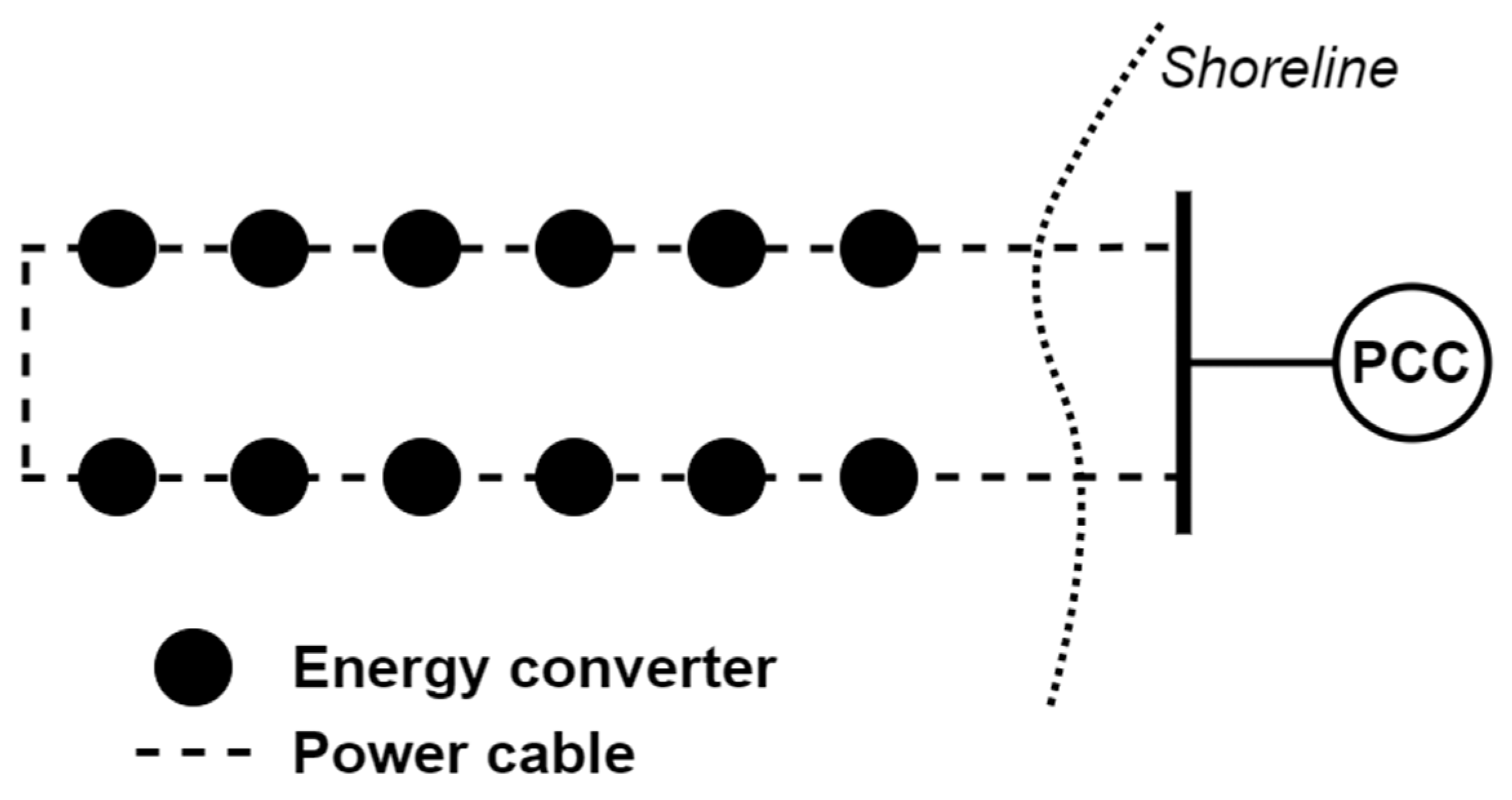
4.3. Double-Sided Ring Topology
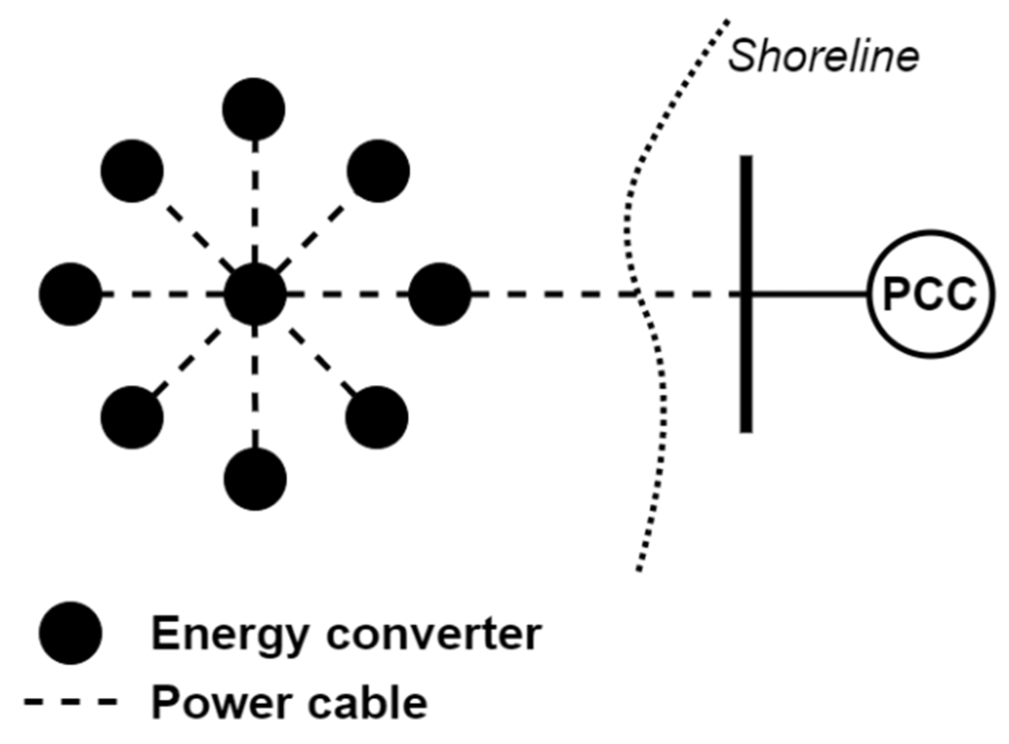
The double-sided ring topology is an attempt to reduce the increased cost of the single-sided ring topology—see Figure 3. Instead of only having an empty cable from the last energy converter to the collection point, energy converters are connected to the return cable. The return cable will, therefore, be utilized more actively and not only primarily for redundancy, as is the case for the single-sided ring topology. This will arguably make the double-sided ring topology less expensive compared with the single-sided ring topology. However, if a fault occurs at either the beginning or the end of one string, the intact side needs to be able to carry the power of all units in the string.

4.4. Star Topology

In the star topology, multiple energy converters are connected to a central energy converter—see Figure 4. The main advantages of the star topology are increased security, improved stability and the possibility of using cables with lower power ratings [4]. Since single energy converters are connected to the central energy converter, the cable from one energy converter to the central unit only needs to be rated for one energy converter, reducing the cost of the cables. The cable from the energy converter in the centre to the collection point onshore, however, needs to be rated for the power level of the whole farm. The single cable from each energy converter gives the system a high degree of redundancy. If one cable fails, the other energy converters will still be able to deliver power to the central collection point. The only way the complete farm can be disconnected is if the cable from the central energy converter to the collection point fails. The voltage regulation of the cables will presumably also be better in this topology, which will improve the stability of the system compared with the other topologies [4]. The star collection grid topology will, however, require more complex switchgear equipment in the central unit, which could significantly increase the cost of the system [4].

4.5. AC Collection Voltage Level

Wave and marine current energy development are still ongoing, and, as of yet, no commercial standards for voltage levels have been established. A trend in the choice of voltage levels can, however, be observed, where most devices produce voltages below 15 kV, and a few designs can produce voltages up to 33 kV [16].

4.6. Cost of AC Collection Grids

In [4], an estimation of the cost of each topology presented above for offshore wind was calculated. The study was more comprehensive than this review paper, but compared the same four topologies. The study estimated the costs of the turbines, generators, switchgear, transformers, hub and installation for a collector system of 33 kV. The study found that the two systems with a ring formation were accompanied by a 2.5–5 times higher capital cost (see Figure 6 in [4]) than the star or radial topologies, but suggested that a lack of redundancy is common practice in smaller offshore wind farms, below 100 MW, to cut down on the installation cost. Another study on electrical wind farm design [22] predicted a slightly smaller increased investment cost for ring topologies, up to 1.58 times greater for a double-sided ring topology than that for a radial topology, and 2.1 times greater for a single-sided ring topology than that for a radial topology.

4.7. AC Cables

The most common subsea cable type for AC transmission in offshore wind farms is cross-linked polyethene (XLPE) insulation with a copper conductor in a 33 kV grid [16]. A report by the Bureau of Ocean Energy Management suggested that the most cost-efficient voltage level for subsea AC transmission below 100 MW is up to 36 kV [26]. The report also described cable type selection and installation considerations in cable design that are not covered in this review.

4.7.1. Static versus Dynamic Power Cables

Once a power cable has been selected for its electrical properties, the amount of protection the cable needs depends on the environment and how much mechanical stress the cable is subject to. In most applications, a cable does not move once deployed and is referred to as a static cable. In ocean energy, the cable installation process is more complex, since the cable will preferably be handled in one long piece and deployed from an ocean vessel. The installation process is one of the most common causes of cable failure [26]. In addition, the cable may have to hang from the energy converter to the bottom of the ocean, subjecting the cable to the movements of ocean currents and waves. The mechanical strength of the cable has to be increased, and it is referred to as a dynamic cable, with the downside of significantly increasing the cost of transmission. One example of increasing the strength is adding more insulation layers [16] to provide more stability during installation and operation. A comparison of prices for static and dynamic cables was conducted in [16] by collecting the cost curve coefficients of several offshore wind farm projects and inserting them into a cost data function to plot the static and dynamic cable prices. From the data in Figure 5 [16], it can, for example, be observed that a dynamic cable is estimated to be 30–60% more expensive for a system voltage of around 36 kV. More information about the design of dynamic cables can be found in [27].

4.7.2. Cost of Cable Installation

The installation of subsea power cables is expensive and risky for the cables. The method used for deploying the cables depends on the type of seabed, as well as obstacles that may determine a special route. The different methods include using a cable plough, remote-operated vehicle (ROV) and excavating a trench, and are described in more detail in [28]. In some cases, a combination of the methods has to be used. The general cost for inner array cable deployment is reported to be EUR 91,000 per day, and on average, 0.3 days are needed per km of cable [28]. For large offshore wind farm projects, the estimated costs of cable deployment were summarized for a range of 150–1000 MW in table E23.37 of appendix E in [29]. The range of possible costs differs extensively depending on the type of cable and installation technique. If, for example, a single cable with a single core is installed in a single trench, the estimated cost is reported to be in the range of GBP 0.3–0.7 M/km.

4.8. Transformers

Transformers are well used in power systems and can have several purposes, including voltage step up or down, measurements, or creating neutral points in three-wire systems. There are many variations that can be tailored for specific applications. Transformers can be produced for both dry and wet environments, as well as utilize different forms of insulation depending on the safety requirements, most commonly oil, called liquid-immersed transformers, or air, called dry-type transformers. For on-land applications, AC transformers of over 1000 MVA and 800 kV are used. For offshore applications, the choice of insulation material is of particular interest, considering the environmental impact of a potential breakdown. Insulation solutions and monitoring for power transformers were reported in [30].
Wet-environment transformers are a commercially available product; however, they have not yet reached the same power and voltage levels as dry-environment transformers. There are several suppliers offering solutions up to 145 kV and 100 MVA [31,32,33]. A wet-environment transformer has the same electrical design as a dry-environment transformer, but is filled with a liquid and pressurized to match the pressure at the depth the transformer will be placed at. The cost of a dry-type transformer is estimated to be 1.3 times higher than that of an equivalent liquid-immersed transformer. In contrast, a wet-environment transformer is up to seven times more expensive than a dry-environment transformer [16].

4.9. Connectors

There are two types of connectors, depending on how and when they are connected, or mated, to the device. Dry-mate connectors are connected above the water’s surface and can then be submerged, while wet-mate connectors can be connected while submerged. Dry-mate connectors are a more mature technology. Hence, the product options come at a higher power rating and lower prices. However, when considering the installation of the devices, dry-mate connectors mean that the installed cable must be longer in order to reach the surface. The extra cost of the cable’s length must be weighed against the reduced cost of a dry connector compared with a wet connector. Most of the connector products were initially developed for the oil and gas (O&G) industry at depths down to 3000 m, but are now extending to include connectors adapted for marine renewables, where 100 m is the usual installation depth.
Dry connectors are commonly used in the O&G sector, with low-voltage and medium-voltage ratings (there are many standards about what constitutes different voltage levels, though a reasonable partition is low-voltage (LV) being below 1 kV, medium-voltage (MV) being between 1 and 35 kV and high-voltage (HV) being anything above 35 kV [16]). According to [16], the highest-rated dry-mate connector on the market is rated at 132 kV and 160 MVA. There are also commercially available connectors with several contacts, for example, with 40 contacts, rated up to 100 A and 3 kV [16].
Wet-mate connectors are mateable using an ROV, diver or a stab-plate (assisted by an ROV), and offer the advantage of connecting the cable directly to the energy converter unit submerged on location. A list of manufacturers of wet-mate connectors can be found in [34]. The report found many suppliers offering power levels of up to 10 MVA and 10 kV, which cover the most common output voltage levels for tidal power units. Wet-mate connectors are mateable for 50–100 connections/reconnections, and most manufacturers offer an expected lifetime of more than 20 years [34], which should cover the expected life span of most renewable energy devices. The costs of wet-mate connectors from four suppliers were estimated to be in the range of GBP 20–250 k for voltages of 6–20 kV in [34] and GBP 100–250 k, or 2–3 times their dry mate equivalent, in [16].
This section has not covered mechanical properties, such as the failure rates or possibilities of adding a fibre-optic cable to the connector (common for wet-mate connectors). This was, however, described in more detail in [34].

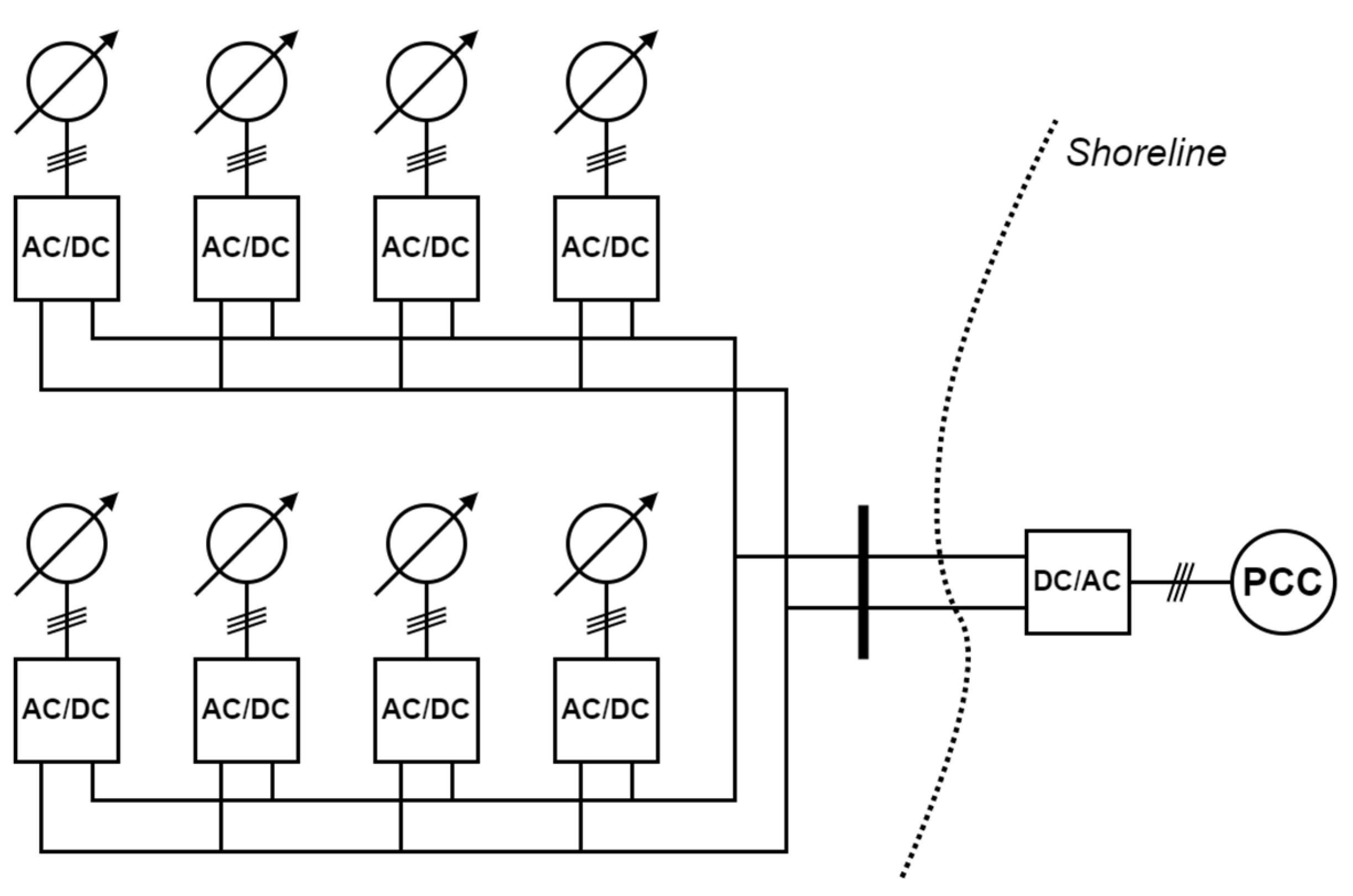
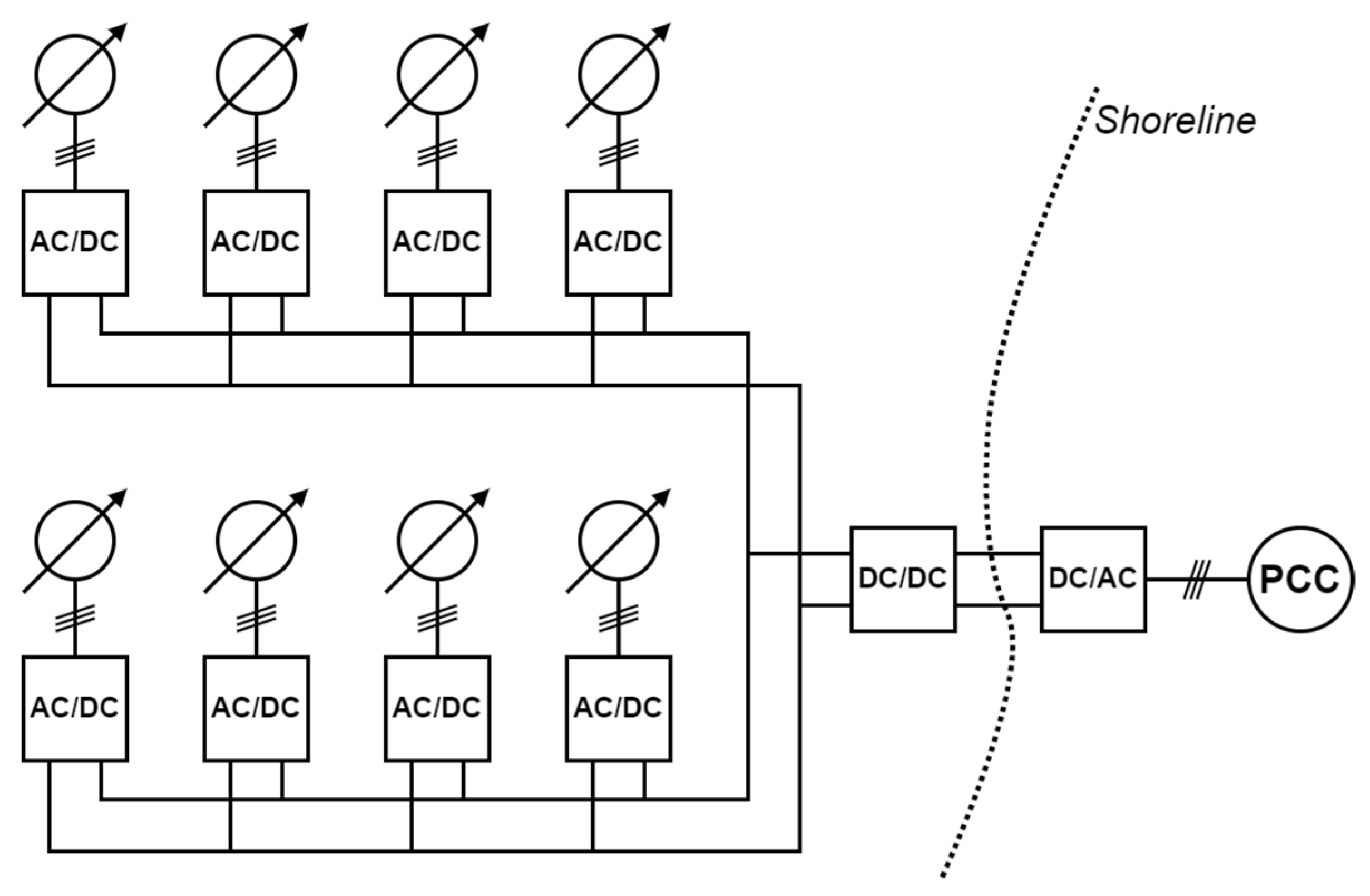
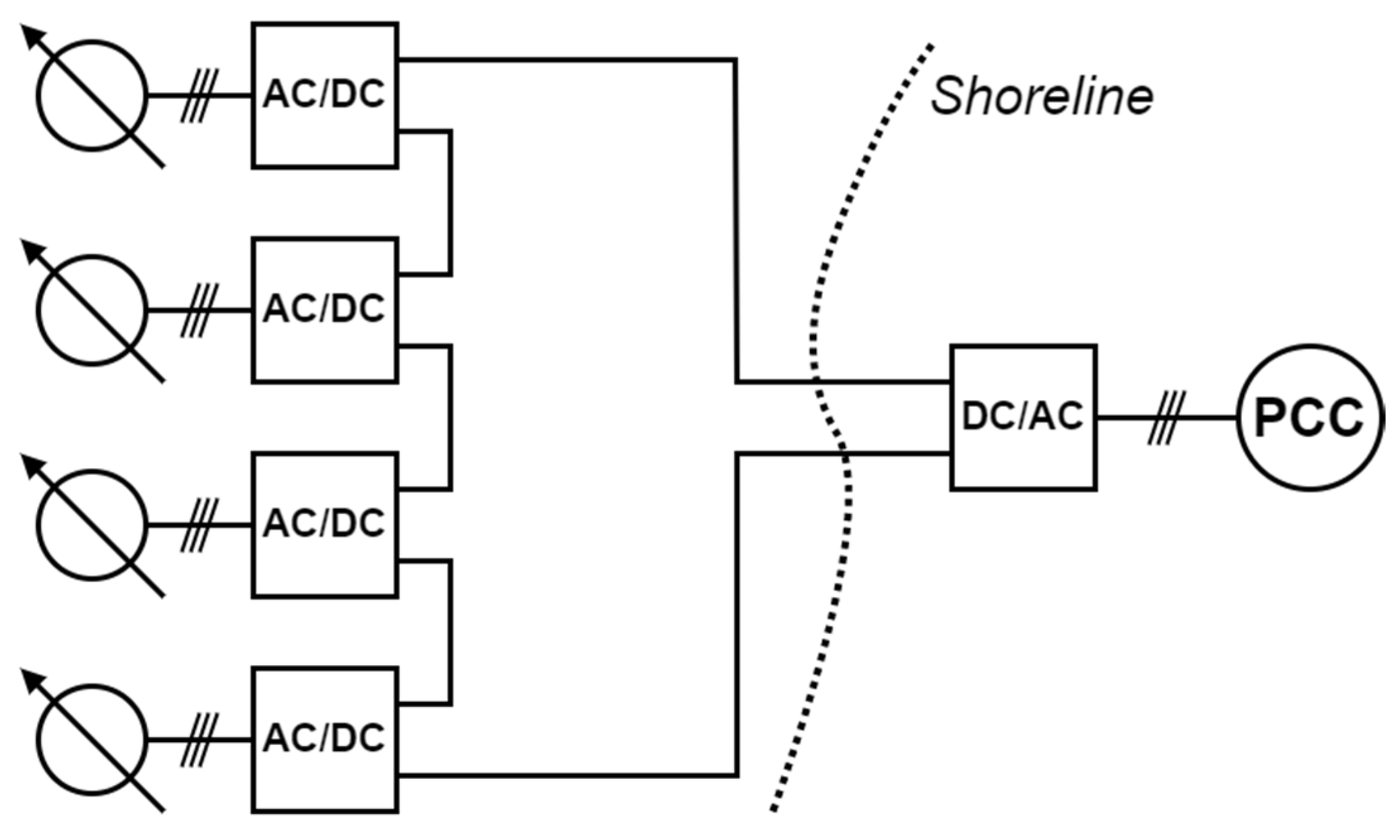
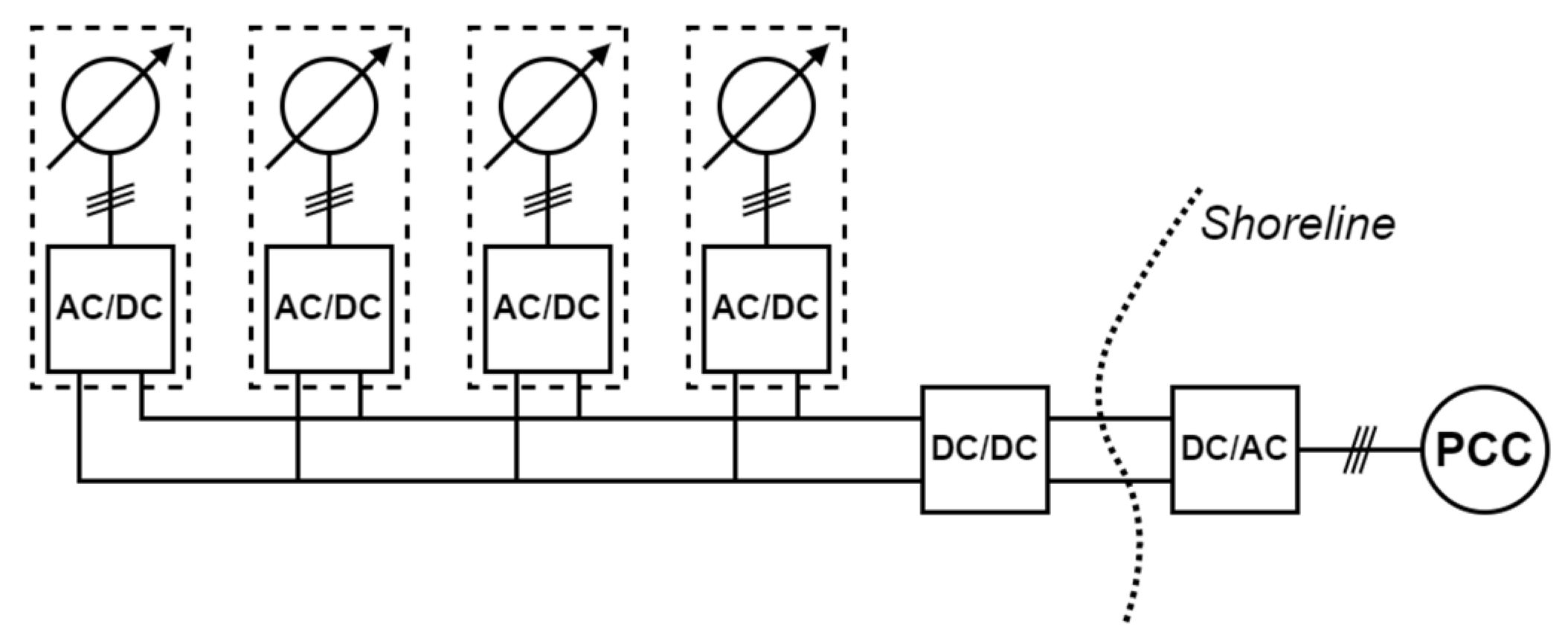
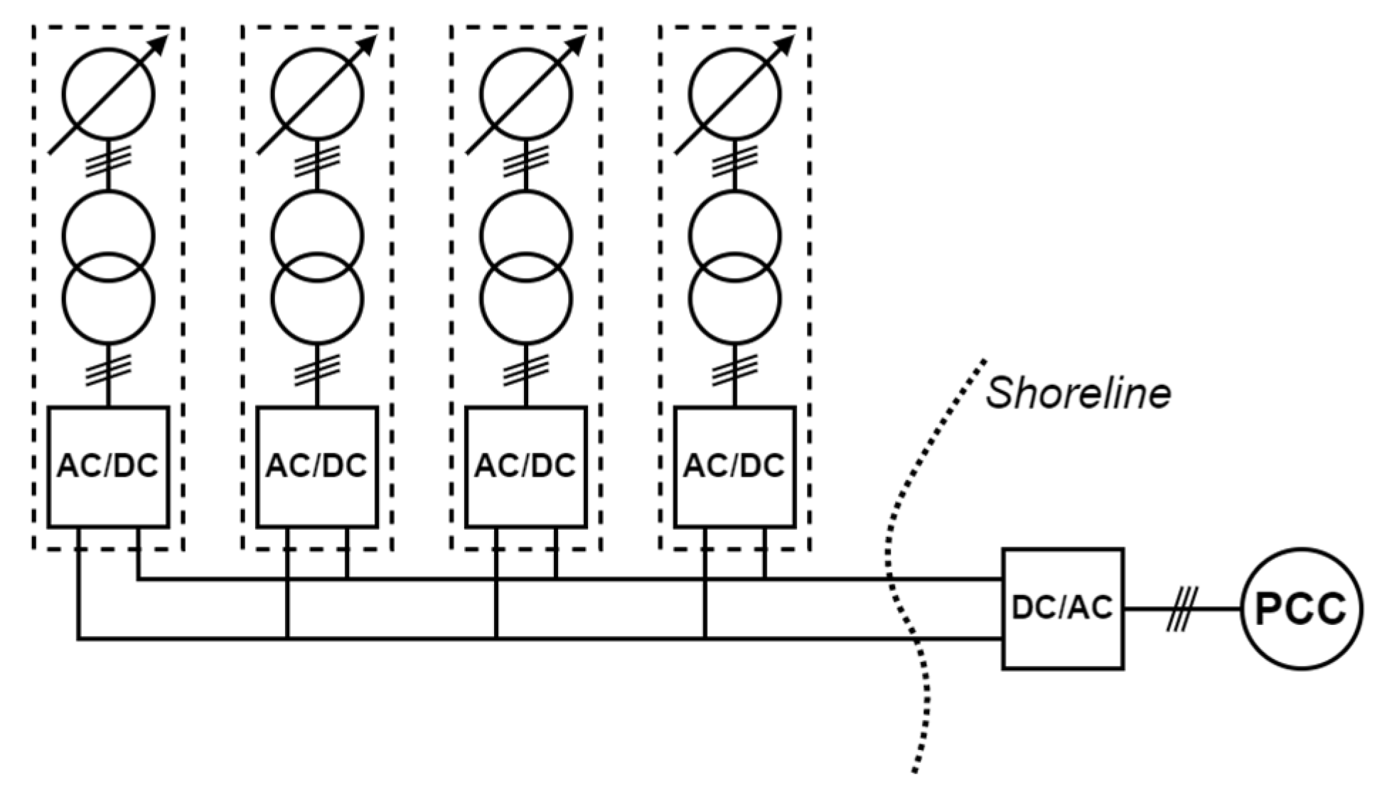
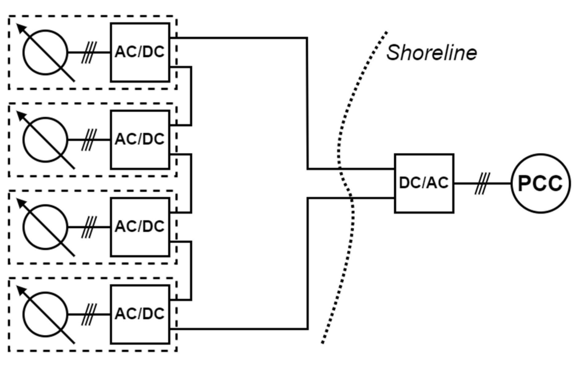
5. DC Collection Grids

In this section, an overview of possible DC collection grid topologies is presented. To the knowledge of the authors, there are no commercial DC collection grids for offshore wind farms. Larger offshore wind farms at a greater distance from the shore are often constructed with HVDC transmission to the shore [16]. The internal collection grid in these farms is, however, still based on AC technologies.
DC collection grids can broadly be divided into two categories: parallel or series topologies. In the parallel topology, the energy converters in the grid are electrically connected in parallel. This means that all energy converters are connected to the same voltage level. In the series topology, the energy converters are electrically connected in series; therefore, the voltage is aggregated over the energy converters in a string. Combinations of parallel and series topologies exist: strings of series-connected energy converters can be parallel-connected, for example. It has also been proposed that the units could be connected individually to a central hub [12]. Extensive reviews and surveys of DC collection grid topologies can be found in [5,12,23,24,35].

5.1. Parallel DC Collection Grids

In the simplest form, parallel DC collection grids have a similar structure to the conventional AC radial topology in Figure 1 [12]. Parallel DC collection grids, therefore, have the same deficiency in redundancy as radial AC collection grids in that, if a fault occurs on the cable, all units on the severed side of the cable will be disconnected. The redundancy can be improved by connecting an extra cable from the last unit in one string to the central collector point in the same manner as the double-sided ring topology [5].
Multiple topologies of parallel DC collection grids can be considered. An important issue is how multiple units are aggregated offshore. In Figure 6, one of the most basic parallel DC collection grid topologies is illustrated. The energy converters are connected radially to a feeder cable, which is connected directly to an onshore inverter. There is no offshore collection point or substation. This topology is characterized by no redundancy due to the use of a single feeder cable. The system is primarily suitable for near-shore applications since there is no central offshore boosting of the voltage before transmission to the shore. This means that every single unit needs to increase the generated voltage to the voltage level of the collection grid. Depending on the technology for generating a DC voltage, this will put various constraints on how much the voltage can be increased from an individual energy converter [36]. The total current transmitted to shore i d c   can simply be expressed, as in Equation (1), as the sum of the currents from each respective energy converter i d o k , where k is the specific unit.
i d c t = k   =   1 k i d o k t
An extension of the single-feeder parallel DC topology is illustrated in Figure 7. In this system, multiple radial feeder strings are connected to a passive offshore connection point (similar systems are discussed in, among others, [8] and [37]). The connection point is a completely passive component and should only act as a busbar with necessary safety, monitoring and control equipment, such as circuit breakers. The substation could be constructed either as a submerged unit, floating unit or a unit on a fixed platform. Since there are multiple feeder cables with energy converters delivering power, the collection system with an offshore connection point offers an improvement in redundancy. If one string were disconnected due to a fault, the other strings could continue to deliver power to the grid. However, if a fault occurred on the cable from the offshore connection point to the onshore inverter, the whole farm would be disconnected from the distribution grid. The cable from the offshore connection point needs to be rated for the power of the complete farm, while the cables in each feeder could be rated at lower power levels. This could be beneficial in large farm systems, where, if the units were connected to the same cable, more high-power cables would be required. Since the voltage level of the whole collection grid is the same, the possible transmission distance will, in the same way as the topology without the connection point, be limited by the power level of the farm and the voltage-boosting capacity of the individual energy converters. For the topology with an offshore connection point, the current transmitted to the shore is the sum of the total currents in each string. This is expressed in Equation (2), where i d c from Equation (1) is summed over all strings n .
i D C t = n   =   1 n i d c n t
If the offshore farm is located far from the shore, it could be necessary to increase the voltage towards HV levels. Therefore, a natural extension of the topology with an offshore connection point in Figure 7 is to include an offshore hub in which the voltage is increased to HV levels. This would enable the farm to be located further from the shore. The topology with an offshore hub is illustrated in Figure 8. The offshore hub is an active component in this topology with power electronics, enabling HV DC/DC conversion. The hub would be constructed on a platform and can be expected to be an expensive and complicated component. In offshore projects with traditional AC collection grids and with HVDC transmission to the shore, the offshore platform is usually one of the single most expensive components [29,38]. HVDC transmission can be necessary to make transmission to the shore possible without too high losses, and it can contribute to improving the redundancy of the farm, since the offshore hub is fed with power from multiple strings with energy converters. The complexity of the system is, however, significantly increased.

5.2. Series DC Collection Grids

In Figure 9, the basic topology of a series DC collection grid is illustrated. The energy converters are connected in series, and the voltage is aggregated over all units. If the voltage output from an energy converter is v d o t , the total voltage from one string is:
v d c t = k   =   1 k v d o k t
In [35], the efficiency of series-connected DC wind farms was evaluated. In comparison with the AC collection and transmission at the Horns Rev offshore wind farm, it was shown that the series-connected DC wind farm could have a lower energy-production cost compared with traditional AC systems, especially for longer transmission lengths. The reason for this is that, since the transmission voltage is the aggregate of the voltage of all energy converters, HVDC transmission can be achieved without an HVDC offshore platform. As noted earlier, the offshore platform can be expected to be one of the single most expensive parts of an offshore wind farm. However, since the transmission voltage is maintained by the individual energy converters, the system needs to be able to handle large power fluctuations or the disconnection of energy converters. In [35], it was shown that the rated voltage of the energy converters needed to be 35% higher than the nominal voltage, where the latter is the transmission voltage level divided by the number of energy converters in one string. Further, the series-connected DC topology will put high stress on insulation. If, for example, the last energy converter in a string (as seen from the ground) is studied, it is obvious that this energy converter needs to be insulated for the full HVDC voltage as referenced to the ground.
A series-connected offshore wind farm topology with an AC/AC converter, a three-phase HF transformer and passive diode rectification was proposed in [9]. It was shown that the concept could be better compared with radial AC systems for energy converters with high power ratings. The concept of a series DC collection grid with HF conversion was further investigated in [10,11], where the emphasis was on evaluating and improving the efficiency of three different AC/AC converters.

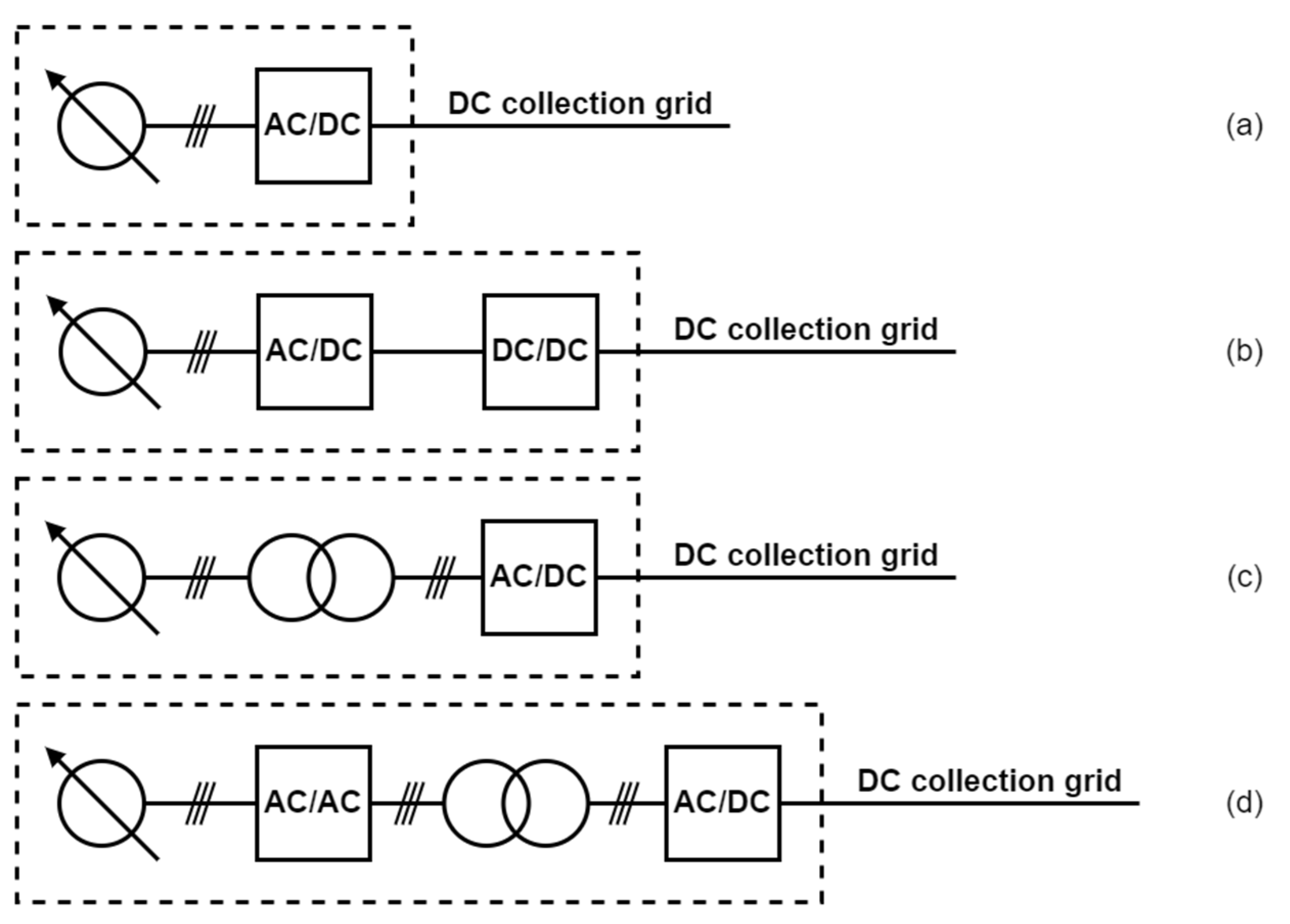
5.3. Technologies for Voltage Conversion from AC to DC

A characteristic of all of the DC collection grid topologies discussed above is the DC voltage output from the energy conversion unit, for example, the wind turbine. The power generation is usually in AC; therefore, an AC to DC conversion step is necessary. This can be achieved in several ways, and an overview of different technologies can be found in [37]. A couple of variants of these strategies are illustrated in Figure 10. The simplest concept is shown in Figure 10a and consists of a one-step rectifier. It could either be an active or passive rectifier. One of the main limitations of this topology is that the output DC voltage from the energy converter is limited by the nominal terminal voltage of the generator [37]. This topology also lacks galvanic isolation.
The topology in Figure 10b offers an extension to the one-step rectification topology. After the AC/DC step, an additional DC/DC converter is included. The DC/DC converter provides the possibility to increase the voltage to higher levels. This DC/DC converter could either be non-isolated or isolated. If an isolated converter is used, the generator will be galvanically isolated from the collection grid.
Another two-stage concept is illustrated in Figure 10c, where a low-frequency (LF) transformer is connected directly to the generator. The transformer increases the voltage, and the AC voltage output from the transformer is rectified at the connection point to the grid. The main benefits of this topology are the high degree of simplicity and the low number of active components. However, an LF transformer can become very large, making the system less appropriate for offshore applications where space limitation is an important consideration.
In Figure 10d, a concept with an AC/AC converter, an HF transformer and a rectifier is illustrated. This is the topology proposed in [9,10,11] for a series-connected DC wind farm. The AC/AC converter enables the use of an HF transformer, which can be produced to be much smaller than an LF transformer. The use of a transformer also increases the security of the system, since the generator will be galvanically isolated from the grid.

5.4. Key Components of a DC Collection Grid

As has been implicitly stated in the previous section, two functions will be necessary if an energy converter is to be connected to a DC collection grid: (1) the AC voltage from the generator needs to be rectified to a DC voltage, and (2) the DC voltage needs to be adjusted to a suitable value for the DC collection grid. Four possible topologies to achieve these goals are discussed in the previous section. The topology that would achieve this in the least disruptive way for the energy converter is the topology with a DC/DC converter in Figure 10b [37]. If active rectification is used, the AC generator can be controlled to achieve optimal power extraction from the energy converter. Further, an isolated DC/DC converter can offer a galvanically isolated boosting capability for higher power levels [39]. Therefore, non-isolated and isolated DC/DC converters will be investigated further in Section 5.4.3. and Section 5.4.4. As the last step in the system, the DC voltage needs to be inverted to AC before the system is connected to the main AC distribution grid. DC/AC converters will, therefore, also be discussed in Section 5.4.2.

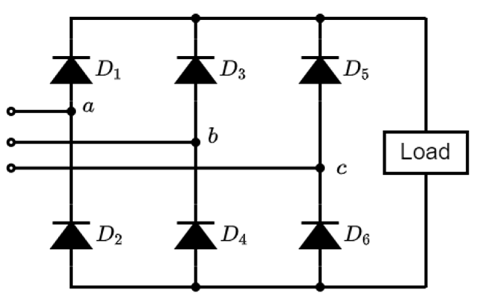
5.4.1. AC/DC Converters

The main function of an AC/DC converter (rectifier) is to transform an AC waveform into a DC waveform. In the most ideal case, the AC waveform is sinusoidal and the DC is a constant value. There are two main categories of AC/DC converters: passive and active rectifiers. A passive rectifier is constructed with passive rectifier diodes, and for a three-phase system, one topology is the three-phase full-bridge rectifier, which is shown in Figure 11 (see, for example, [36]). The phase voltages a , b and c are rectified to the load. The output from the full-bridge rectifier will inherently contain harmonics; therefore, it will, in most applications, be necessary to filter the output. It should also be noted that, with a passive rectifier, there is no active control of the rectification process.
The voltage and power rating of the full-bridge rectifier will mainly be decided by the rating of the rectifier diodes. Power rectifier diodes for applications with higher voltage and power are available for voltage levels from a few hundred volts up to 10 kV and currents ranging from 1 A to 10 kA [40]. These diodes are, however, meant for applications with low frequency. For high-frequency situations, fast-recovery diodes are available, but with lower voltage and current ratings of up to 6 kV and 3 kA and higher expected conduction losses [40]. If a higher voltage and current rating are required, the diodes can be connected in series or in parallel [41].
If controllable switches are used, active control of the rectification process can be achieved. If the rectifier is connected to inductors, for example, the inductance in a generator, the rectifier can be used to increase the voltage. This type of topology is sometimes called a boost rectifier [42]. The active control of the rectifier makes it further possible to implement maximum power point-tracking schemes to optimize the power extraction from the energy converter. In Figure 12, a three-phase rectifier with active switches is shown. The switches here are IGBTs. It is, however, possible to use other types of controllable switches, such as thyristors or MOSFETs. If conventional thyristors, such as silicon-controlled thyristors (SCR), are used, the switch can only be turned ‘on’, and then the current must be commuted for the device to turn off. Most modern thyristors are, however, constructed to be able to switch both ‘on’ and ‘off’ [43]. Achieving ‘turn off’ for a thyristor is, however, a nontrivial task; therefore, manufacturers often incorporate a gate–drive system for this purpose in the switch module. This type of device is called an integrated-gate commuted thyristor (IGCT) [43]. IGBTs and MOSFETs can both be switched ‘on’ and ‘off’.
Thyristors can generally handle larger voltages and currents compared with IGBTs and MOSFETs. The possible switching frequencies of thyristors are, however, usually lower. Conventionally, the MOSFET has not been able to operate in as a high voltage and current region as the IGBT and has, therefore, not been considered for medium- or high-power applications. The development of semiconductor devices is rapid; therefore, the voltage and current ratings are continuously increasing. Typical ratings that can be found are, for IGBTs, 6.5 kV and 750 A; for IGCTs, 6.5 kV and 3.8 kA; and for MOSFETs, 10 kV and 10 A [44]. The choice of switching technology will, therefore, be based on the specific application with regards to factors such as the voltage and power levels, costs, efficiency and reliability. If the voltage or current rating of the available switching devices is not sufficient, a multilevel technology or modular technology has to be considered—see Section 5.4.2.

5.4.2. DC/AC Converters

A large variety of DC/AC converters (inverters) are available—see, for example, [45,46,47]. The basic operation of an inverter is to generate an output voltage with a stepped waveform from a DC input voltage. Increasing the number of voltage levels makes the stepped waveform approach a sinusoidal AC waveform [48]. As an example of a DC/AC converter that could be used in a DC collection grid, a five-level diode-clamped inverter is illustrated in Figure 13. The diodes are used to balance the voltage over the switches, and, for five levels, the required voltage blocking level of the switches is V d c / 4 . The reverse-blocking voltage of the diodes will, however, differ. The diodes D 1 and D 3 need to be able to block 3 V d c / 4 . For larger DC voltages, it will, therefore, be necessary to series-connect multiple diodes. If all diodes are assumed to have the same rating, the number of diodes needed in one phase will be given by m 1 × m 2 , where m is the number of voltage levels of the inverter [47]. The number of diodes is, therefore, increased quadratically with regards to m . This quadratic increase in the number of diodes usually puts a feasibility limit on the number of voltage levels of the converter at five levels [47]. After five levels, the number of diodes needed to be connected in series becomes unmanageable.
If larger voltage and power levels are considered, a more traditional technology, such as the five-level diode-clamped inverter, will probably not be feasible due to the limits of the voltage and power rating of state-of-the-art semiconductor devices. In this case, a modular multilevel converter topology will need to be considered [45]. The basic principle of modular multilevel converters is the series connection of several submodules consisting of, for example, full-bridge or half-bridge converters. The interconnection of multiple devices decreases the voltage over each respective submodule and, if a large number of submodules is used, it is possible to create an AC voltage waveform that is nearly sinusoidal. Even though the modular multilevel converter is a recent invention, with one of the first patents from the early 2000s, it has been widely used in HVDC applications [45]. There has also been a growing interest in using modular multilevel converters in MV applications, for example, microgrids [45]. In [49], different types of modular multilevel converters for HVDC applications were investigated, and the control of voltage source converters was discussed extensively in [50].

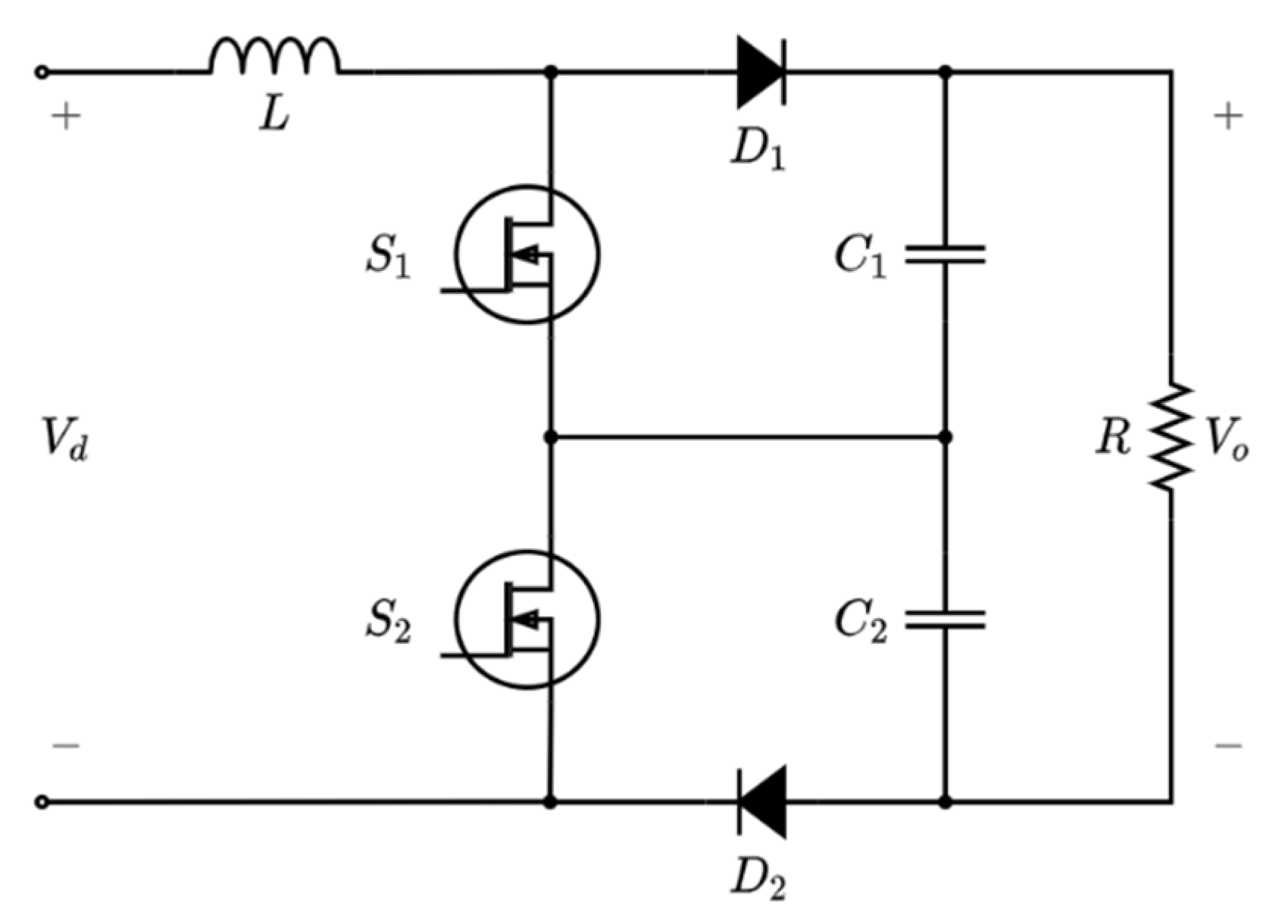
5.4.3. Non-Isolated DC/DC Converters

An extensive overview of different types of DC/DC converters can be found in [39]. The main function of the DC/DC converter is to either increase or decrease a DC voltage. DC/DC converters can be constructed as non-isolated or isolated [39]. In this section, an overview of basic non-isolated DC/DC converters will be presented. In Section 5.4.4., isolated DC/DC converters will be discussed. Since the focus of this article is on DC grids, and one of the main functions of the DC/DC converter is to increase the voltage, primarily DC/DC converters that can step up the voltage will be considered. For information about isolated and non-isolated step-down DC/DC converters, see, for example, [51].
In Figure 14, a conventional non-isolated boost converter is shown. This topology represents one of the simplest approaches to performing a step-up DC/DC conversion. In essence, the circuit consists of three elements: one inductor, one diode and one switch, which is a MOSFET here. Included is also a capacitor to decrease the voltage ripple and a resistive load. The conventional, non-isolated boost converter is generally not suitable for high-power and HV applications [52]. The semiconductor devices need to be rated for the voltage and current injected into the load, which significantly reduces the range of possible output voltages (see Section 5.4.1. for examples of typical ratings for power rectifier diodes and power MOSFETs). Furthermore, due to the issues associated with, among others, the parasitic resistance in the inductor, the efficiency of the boost converter decreases when the step-up in voltage is increased [52]. These factors make the non-isolated boost converter most suitable for applications with low to medium power levels and where a high voltage step-up ratio is not a requirement [52]. These factors can make the conventional boost converter less suitable for marine energy applications. However, the simplistic and, therefore, less expensive design makes this topology an interesting option.
Due to factors such as the simplicity and applicability of the conventional non-isolated boost converter, the technology has been subject to intense research, and many different topologies have been proposed [39]. If a higher output voltage is required, one technology that is used is the non-isolated three-level boost converter shown in Figure 15. In this topology, the output voltage is divided over the semiconductor devices, which decreases the voltage stress of the components by half. It should, however, be noted that, for the same reasons as the conventional non-isolated boost converter, the three-level boost converter is not suitable for high step-up voltages [52]. Regarding the switching frequency, this is mainly a design consideration. Usually, a high switching frequency is preferred, since components, such as the inductor and the capacitor, can be made smaller. However, when the switching frequency is increased, the power losses in the switches are increased. Switching frequencies are typically at least 20 kHz to reduce audible noise [36].
As noted above, many different types of non-isolated DC/DC converters have been developed, and the topologies presented above are only examples of technologies that could possibly be used in marine energy applications. Other established technologies that could be investigated for marine energy applications are the buck-boost converter, which can both step-up and step-down the voltage, the classical Ćuk converter and the SEPIC converter. Furthermore, many different topologies have been proposed for voltage step-up with a wide conversion ratio, for example, the cascaded boost converter. More topologies can be found in the literature—see, for example, [39,52].

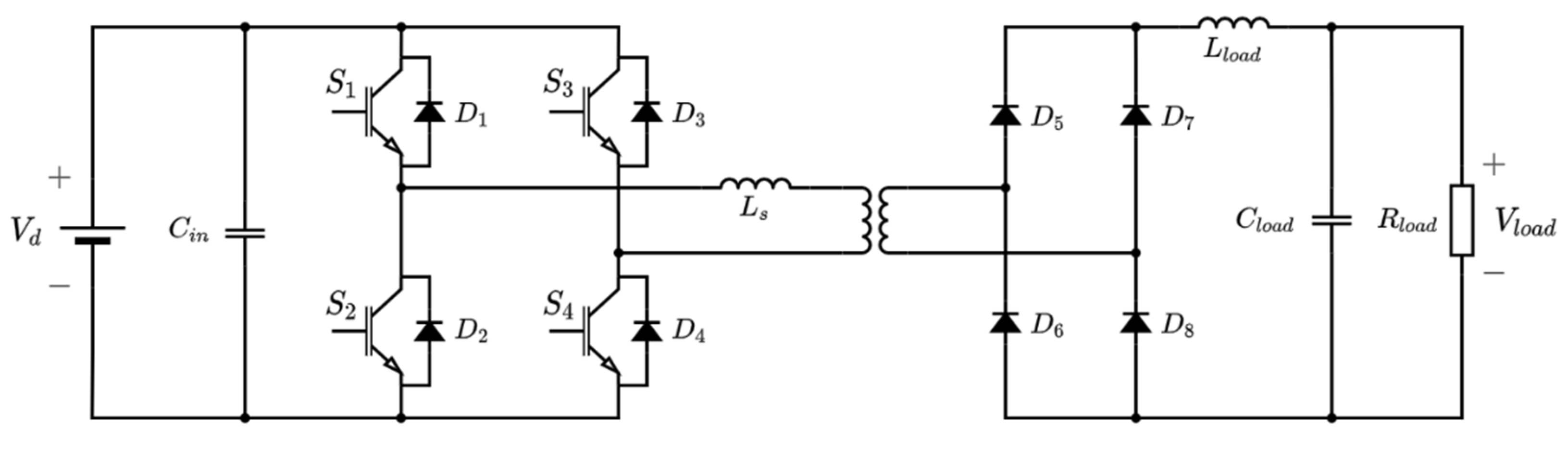
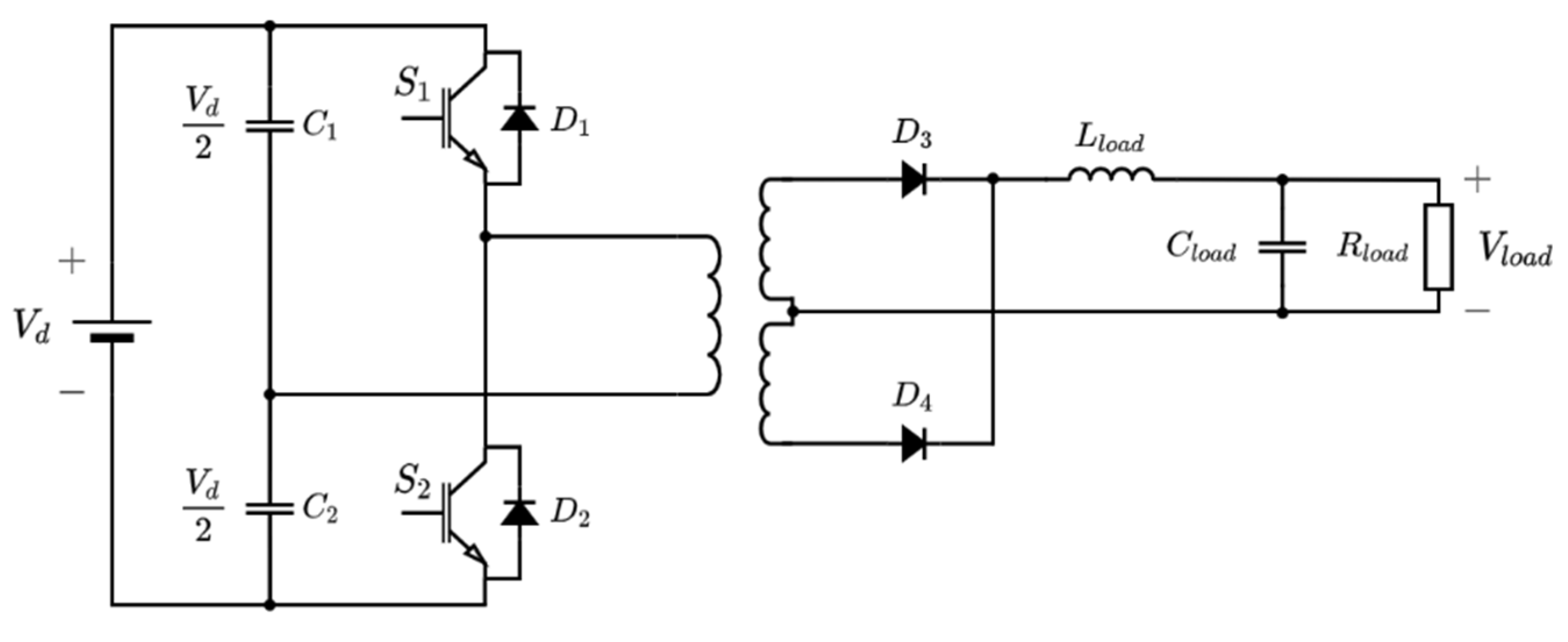
5.4.4. Isolated DC/DC Converters

The obvious benefit of an isolated DC/DC converter is galvanic isolation. In applications with higher power and voltage, it can be necessary to use converters with galvanic isolation to protect the generator against unwanted currents. The use of components with galvanic isolation will, however, require a magnetic coupling, which will increase the size of the components. In high-power systems, it can also be necessary to use magnetic coupling to achieve a high voltage step-up [39]. Furthermore, the use of magnetic coupling can improve both the efficiency and reliability of the system [39]. In [53], three isolated DC/DC converter topologies for a wind farm with a DC collection grid were compared with regard to power losses. Of the three topologies, that is, single active bridge converter, resonant converter and full-bridge converter, the latter topology was shown to have the lowest losses. Further, the full-bridge converter was smaller and had a lower peak voltage and current. However, more rectifier diodes were needed in the full-bridge topology. Since the full-bridge converter has lower losses and can possibly be more space-efficient due to the smaller transformer, the topology will be further investigated below. The more simplistic half-bridge converter will also be discussed.
The circuit of a basic full-bridge converter is shown in Figure 16. In the full-bridge converter, an H-bridge of switches (for example, IGBTs) is used to create an HF square wave, which is fed to an HF transformer. The mass of a transformer is inversely proportional to the frequency of the voltage. Therefore, if the frequency is increased, the size of the DC/DC converter can be reduced. This can be beneficial in offshore applications, where space limitation is an important consideration. The increased voltage is rectified by an H-bridge with passive rectifier diodes, which makes the full-bridge converter unidirectional. Multiple switching strategies of full-bridge converters can be found in the literature [39,53]. An easy and straightforward approach for switching is to use duty cycle control. In this approach, the output voltage from the converter is controlled by modulating the duty cycle of the switches in the active H-bridge. This strategy, however, results in large losses, since the switches are turned ‘off’ at full voltage [53]. The rating of the semiconductor components will be decided by the input and output voltages. If a large output voltage is required, it can be necessary to series-connect multiple diodes. For large input voltages, it can be necessary to series-connect multiple full-bridge converter units or use a modular multilevel technology [54]. Regarding the typical rating of semiconductor devices, see Section 5.4.1.
A simpler version of the full-bridge converter is the half-bridge converter in Figure 17. The half-bridge converter only has two switches (here, IGBTs), and the two other switches are replaced with large-value capacitors. The voltage over the primary side of the transformer is half of that of the full-bridge converter. This means that, for a given power level, the switches must be able to handle twice-as-large currents. Therefore, the half-bridge converter is usually suitable for lower power levels than the full-bridge converter [42]. However, fewer active components imply a more robust and reliable design, which can make the half-bridge converter a feasible option to consider for marine energy applications.

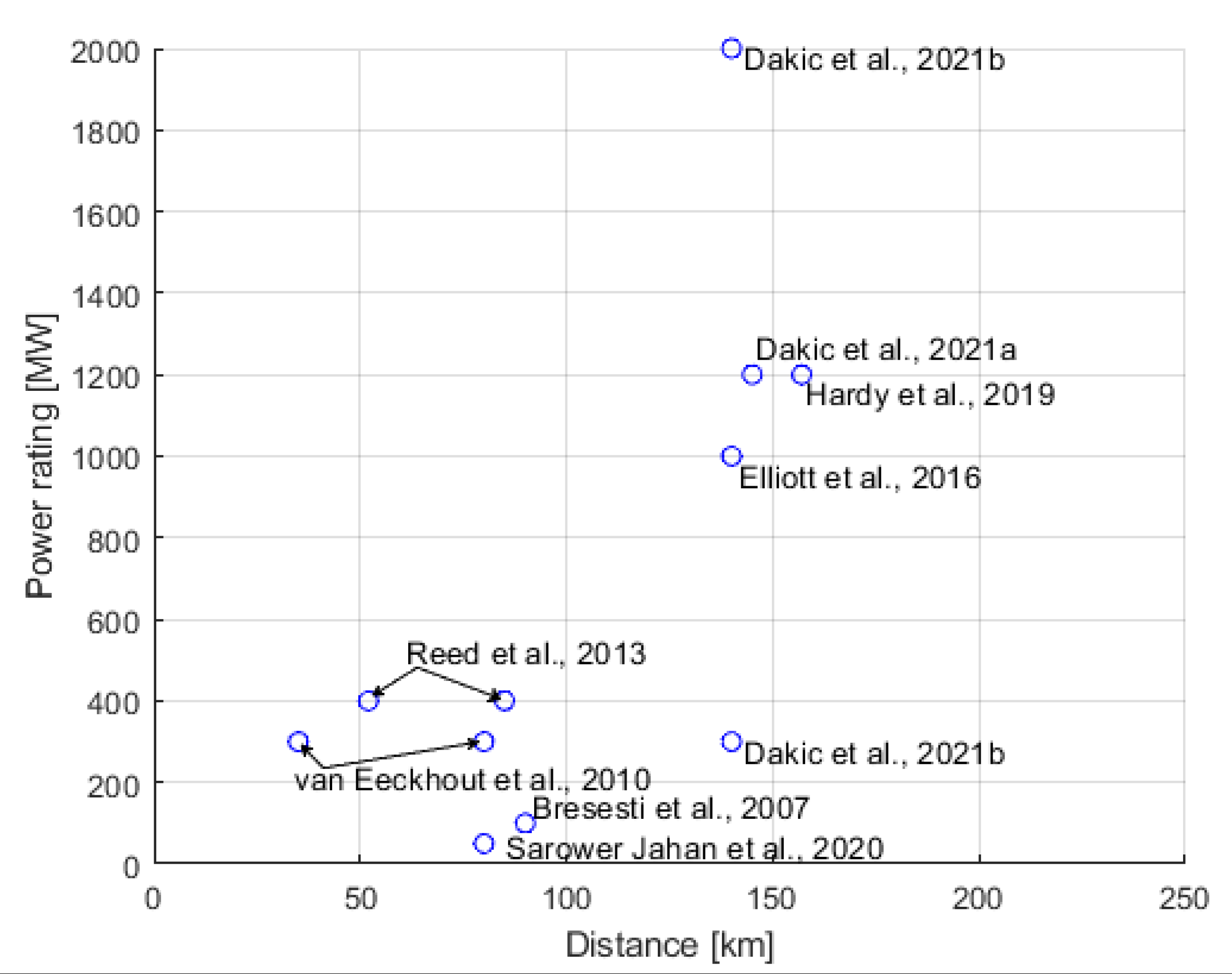
6. AC or DC Transmission in Offshore Applications

To avoid high losses and excessively high current ratings of equipment, large offshore energy farms transmit the generated electrical power to the shore using high-voltage alternating current (HVAC) or high-voltage direct current (HVDC) [55]. In the early large-scale offshore wind power farms, HVAC was used for transmission. However, as both the size of the farms and the distances to the shore have increased, the number of projects using HVDC technology has also increased [6,56].
The reason for using HVAC is mainly due to the possibility of utilizing standard transformers to change the voltage levels and the simple design of protection systems compared with HVDC [57]. HVAC has been used for a long time and is considered a matured technology with a high degree of standardization, which makes the availability of components higher than that for HVDC.
There are mainly two different technologies used for HVDC transmission: line-commutated converter (LCC) HVDC and voltage-source converter (VSC) HVDC. LCC HVDC is based on thyristors as switching elements and can only transfer power between two or more active grids, and would, therefore, need an auxiliary start-up system for marine energy applications [58]. LCC HVDC might be less expensive for power ratings of hundreds of megawatts [6], though it is deemed not suitable for offshore applications due to the high space requirements and susceptibility to AC network disturbances [55]. VSC HVDC has lower space requirements and does not need a separate start-up system, which makes it more suitable for offshore applications [56].

Limitations of HVAC

In submarine HVAC cables, the capacitance is high, which results in both resonance issues and reduced power transmission capacity due to the high charging current. Long cables with high charging current can be compensated using, for example, Static VAR-compensators, which is a difficult and costly task [59]. Ideally, compensation is installed at several points along the cable, but practical limitations often result in possible installation only at the receiving or sending end of the cable. In HVDC cables, there is no or very low charging current, which both reduces losses and voltage drop, but also increases the amount of transferrable power compared with HVAC and eliminates the need for costly compensation units.
An AC system that is synchronously coupled to the grid may experience propagating faults. A fault in one part of the grid will propagate to other parts of the grid. In DC grids, the energy converters will not have a significant impact on the short-circuit current in the main AC grid, since they are not synchronously coupled [60]. Another benefit of HVDC is that, if HVDC is used together with a voltage source converter technology, it is possible to provide ancillary services to the main AC grid through fast control of active and reactive power and frequency response [61].
One disadvantage of HVDC transmission is that HVDC requires more power electronic components compared with traditional HVAC transmission technology, which increases the investment cost. AC/DC and DC/AC converter stations are also costly, which leads to HVDC systems having a higher fixed cost associated with station infrastructure than HVAC [56]. The marginal cost per km of transmission is lower for HVDC, because it requires less cable material and exhibits lower power losses.
As HVDC has higher fixed costs, but lower marginal costs; at a certain distance, HVDC transmission will be the less expensive option compared with HVAC [62]. At what distance the cost for DC transmission and AC transmission is equal has been assessed in multiple studies. Studies discussed in [63] and [3], for example, suggested a break-even distance of 30–50 km, while a techno-economical study in [6] showed that, for a 100 MW wind farm, the break-even distance is 90 km. In [64], the break-even distance for a farm of 1 GW was estimated to be 120–160 km. The aforementioned studies and [65,66,67,68,69] are summarized in Figure 18. At what distance cost parity between HVDC and HVAC transmission occurs depends on factors such as the need for reactive compensation, voltage levels and right of way, and will be more or less unique for every project.

7. Collection Grids for Marine Energy Resources

In this section, five different DC collection grid topologies, based on the DC collection grids and energy conversion topologies presented in Section 5, are discussed from the perspective of marine energy converters. Factors such as size, cost and losses are considered. The topologies are evaluated from the perspective of marine energy converters that are either submerged or placed on a platform or floating. The considered topologies are presented below.
Topology 1 (T1) is a parallel-connected DC collection grid without separate boosting steps. This is the topology illustrated in Figure 19. The dashed box is used to indicate the marine energy converter.
Topology 2 (T2) is also a parallel-connected DC grid. However, an additional DC/DC conversion step is included in the marine energy converter. This topology is illustrated in Figure 20.
In the third case, Topology 3 (T3), the aggregation of power from the WECs is conducted after the rectification in the marine energy converter at a central offshore DC/DC converter. This converter could, for example, be submerged or placed on a floating structure. The third topology is illustrated in Figure 21.
In Topology 4 (T4), a transformer is included directly after the generator, and the AC voltage from the transformer is rectified [70]. This allows the voltage to be increased closer to the generator and the DC/DC converter to be omitted. Topology T4 is illustrated in Figure 22.
In Topology 5 (T5), the marine energy converters are connected in series to a DC collection grid. As discussed in Section 5.2., this enables the transmission voltage to be increased to higher levels without the use of external DC/DC converters. The output voltage from the generator is rectified in the marine energy converter by a single rectifier, and no additional boosting step is utilized. Topology T5 is illustrated in Figure 23.

7.1. Submerged Energy Converter

A submerged marine energy converter would encounter varying differences from a device placed on a platform or floating. One of the significant advantages for all of the five considered topologies in the case of a submerged device is that the device can be moored and allowed to stand on the seabed. This reduces the complexity and cost of platforms or floating structures, which have a very high capital investment [71]. In the case of marine energy resources, it also allows the possibility of exploiting the potential of deep seas with high wave energy availability without significantly increasing the investment cost [72].
The radially connected Topology T1 will probably be one of the least expensive topologies. This is due to an expected lower investment cost, since fewer power electronic converters are required compared with the other topologies. However, due to there being no additional boosting step for the voltage, neither in the marine energy converter nor in an external hub, and the limitation of voltage boosting from an individual marine energy converter using a boost rectifier [37], Topology T1 is expected to have high transmission losses and is limited to near-shore applications.
The disadvantage of the low collection grid and transmission voltage in Topology T1 can be mitigated by adding a DC/DC converter to each marine energy converter. The boosting of the voltage will decrease the collection and transmission losses and enhance the possibility of far-from-shore applications. However, the addition of several DC/DC converters will increase the cost and the number of power electronic components, such as IGBTs and diodes. A system with DC/DC converters will also have significant power losses in the power converters contributable to, for example, switching and conduction losses in the IGBTs. Therefore, the decreased losses for the transmission of power from the marine energy converters to the shore must be weighed against the power losses in the DC/DC converters.
In Topology T3, the investment cost of the system is expected to decrease compared with topology T2. This is because of the reduced cost of only requiring one or a few central DC/DC converters in a hub compared with installing a DC/DC converter in each marine energy converter. Additionally, the individual DC/DC converter must also be rated for a wide spectrum of power levels from a single unit due to varying wave and marine current conditions. On the other hand, the power variability can be decreased with a suitable farm-placement strategy [73]. This reduces the need to rate the DC/DC converter for a wide spectrum of power levels, and hence makes the manufacturing of the component easier and less expensive.
The transmission losses are expected to decrease for Topology T3 compared with Topology T1. However, the technical limitations of the maximum-rated DC/DC converters available on the market limits the rating of the marine energy farm, that is, how many marine energy converters that can be connected to a single DC/DC converter. A medium-frequency (MF) or HF transformer is a core part of an isolated DC/DC converter, for example, a full-bridge converter. The size of the core can be made smaller by increasing the frequency. Since the size of the core can be reduced when the frequency is increased, the smaller core in MF and HF transformers would require less copper wire for the same turns ratio as an LF transformer; therefore, an MF or HF transformer should have lower copper losses [74]. The reduced size of HF or MF transformers also implies that the DC/DC converter could be constructed to be much smaller compared with directly using an LF transformer (compared to Topology T4). This could be a significant advantage in the case of marine energy applications, where space limitation is expected to be a significant constraining factor. However, an MF or HF transformer is expected to have higher eddy current losses [75]. It should also be observed that MF and HF transformers for high-power applications are unconventional designs. Most commonly, transformers are designed for utility grids with a low frequency. Therefore, special attention will be needed when designing a transformer for MF and HF applications [76]. The implication is that, even if the use of a DC/DC converter can contribute to decreasing the size of the marine energy converter and lowering transmission losses, the need for a highly custom-made component can contribute significantly to increasing the investment cost of the system.
Topology T4 utilizes an LF transformer to increase the collection and transmission voltage. This decreases the power losses without the increased complexity of manufacturing DC/DC converters with MF or HF transformers. However, due to the larger size of the LF transformer, the transportation and installation of the marine energy converter at the offshore site are expected to be more complex.
Topology T5 uses the series connection of marine energy converters to increase the transmission voltage, thereby saving the cost of the DC/DC converters or transformers used to increase the voltage for transmission in Topologies T2 and T4, respectively. However, the voltage to the ground for the last marine energy converter device in the series connection will correspond to the total transmission voltage, which can be problematic from the perspective of electrical insulation. To partially overcome this, the ground could be placed in the middle of the series connection to limit the voltage to the ground. Studies have shown that this topology can be preferred for higher-rated wind power generators, where it leads to reduced losses and is possibly economically less expensive [9]. This topology could, therefore, also be preferable for higher-rated marine energy converters.
The submerged system also has a possible advantage with regards to cooling, which applies to all of the topologies discussed above. Seawater can be used as a natural or passive cooling system. The losses in IGBTs and diodes are linearly dependent on the temperature [77]. Hence, the lower temperature of seawater will have a positive effect on the power electronics components leading to lower power losses. This will increase the reliability of the power electronics components and transformer through operation at stable temperatures. It will lead to a decreased need for cooling components and rotating parts, such as fans and heat sinks. The natural cooling system can also reduce the usage of cooling oil, which will be preferred in the offshore environment due to the fear of leakage. Some of the important characteristics of the considered topologies with submerged marine energy converters are summarized in Table 1.

7.2. Energy Converter on Platform or Floating

The weight and size of the power electronic components and carrying capacity of the marine energy converter would determine the necessity of using a platform or placing the components with an already floating marine energy converter [71].
Since Topology T1 consists of fewer power electronic components, it can be possible to place the components in the marine energy converters. The deployment and maintenance costs would be expected to decrease due to the easier access to the electrical components compared to the submerged system. The power losses would also increase due to the higher temperature of electronic components on the platform compared with a submerged system. The thermal conductivity of air is less than that of water. This leads to a linear increase in IGBT and diode losses with respect to temperature [77]. Active cooling needs to be provided for this topology [78].
The electrical components in the topologies would be similar to those in the submerged case. Additional components for cooling could be required for the non-submerged case. However, the total cost for the power electronic components is expected to be unchanged compared with the submerged system.
In the case of Topologies T2 and T3, the possibility of making the DC/DC converter smaller and lighter due to the use of MF or HF transformers can increase the possibility of these components being placed on the marine energy converter. However, the floating marine energy converter must be designed with enough carrying capacity and space to handle these components. The cost and power losses would follow the same trend as the submerged marine energy converter. However, since access to the marine energy converter would be easier in the non-submerged case, the maintenance cost can be expected to be lower compared with the submerged case.
A fixed platform structure would probably be necessary with the inclusion of the LF transformer in Topology T4. This increases the cost significantly and limits the placement of marine energy farms up to a certain distance offshore.
The cost, pros and cons of the power converters would remain similar to the submerged case for all of the topologies due to the unchanged electrical network architecture. Maintenance is easier due to the ease in the reachability of the platform compared with the seabed. However, the losses would probably be expected to increase, as explained above. An active cooling method is most likely required due to the placement of electrical components in a dry/semi-dry atmosphere.
Important characteristics of the considered topologies with non-submerged marine energy converters are summarized in Table 2.

8. Summary and Conclusions

In the present article, an overview of different AC and DC collection grid topologies was provided and limits for long-distance AC and DC transmission were investigated. The radial AC topology is one of the most common layouts of AC grids for wind farms. Multiple different DC collection grid topologies for wind farms have been proposed in the literature. In studies on wind farms, it has been shown that a DC collection grid layout can be more beneficial than traditional AC regarding power losses and investment costs. When evaluating different DC topologies for marine energy resources, it can be observed that the challenges and possibilities are sometimes different depending on whether the energy converter is placed on the seabed or a fixed platform, or is floating. Various advantages and disadvantages can be identified for the different topologies, and, in the end, a site-specific techno-economic assessment will probably determine which topology will be the most beneficial for a specific case.

Author Contributions

Conceptualization, C.F., M.I.U., J.F., E.J., I.T. and K.T.; methodology, C.F., M.I.U., J.F. and E.J.; formal analysis, C.F., M.I.U., J.F. and E.J.; investigation, C.F., M.I.U., J.F. and E.J.; writing—original draft preparation C.F., M.I.U., J.F. and E.J.; writing—review and editing, C.F., M.I.U., J.F. and E.J.; supervision, I.T. and K.T.; project administration, I.T. and K.T.; funding acquisition, I.T. All authors have read and agreed to the published version of the manuscript.

Funding

This research was funded by Uppsala University, Sweden, STandUP for Energy, OESA project, co-financed by the European Union under the European Regional Development Fund (ERDF) within the Interreg North Sea Region Programme 2015–2020, Swedish Energy Agency (PA no. 48347-1), and EU-SCORES project financed by the European Union’s Horizon 2020 and Green Deal Research and Innovation Programme under the grant agreement No. 101036457.

Institutional Review Board Statement

Not applicable.

Informed Consent Statement

Not applicable.

Data Availability Statement

Not applicable.

Conflicts of Interest

The authors declare no conflict of interest. The funders had no role in the design of the study; in the collection, analyses, or interpretation of data; in the writing of the manuscript; or in the decision to publish the results.

References

  1. Lorenczik, S.; Zavala, P.B.; Hungerford, Z. IEA Electricity Market Report July 2021; IEA: Paris, France, 2021. [Google Scholar]
  2. Uihlein, A.; Magagna, D. Wave and Tidal Current Energy-A Review of the Current State of Research beyond Technology. Renew. Sustain. Energy Rev. 2016, 58, 1070–1081. [Google Scholar] [CrossRef]
  3. Green, J.; Bowen, A.; Fingersh, L.J.; Wan, Y. Electrical Collection and Transmission Systems for Offshore Wind Power: Preprint. In Proceedings of the Offshore Technology Conference, Houston, TX, USA, 30 April–3 May 2007. [Google Scholar]
  4. Quinonez-Varela, G.; Ault, G.W.; Anaya-Lara, O.; McDonald, J.R. Electrical Collector System Options for Large Offshore Wind Farms. IET Renew. Power Gener. 2007, 1, 107–114. [Google Scholar] [CrossRef]
  5. Srikakulapu, R.; Vinatha, U. Electrical Collector Topologies for Offshore Wind Power Plants: A Survey. In Proceedings of the 2015 IEEE 10th International Conference on Industrial and Information Systems, ICIIS 2015-Conference Proceedings, Peradeniya, Sri Lanka, 18–20 December 2015; Institute of Electrical and Electronics Engineers Inc.: Piscataway, NJ, USA, 2016; pp. 338–343. [Google Scholar]
  6. Bresesti, P.; Kling, W.L.; Hendriks, R.L.; Vailati, R. HVDC Connection of Offshore Wind Farms to the Transmission System. IEEE Trans. Energy Convers. 2007, 22, 37–43. [Google Scholar] [CrossRef]
  7. Li, Z.; Song, Q.; An, F.; Zhao, B.; Yu, Z.; Zeng, R. Review on DC Transmission Systems for Integrating Large-scale Offshore Wind Farms. Energy Convers. Econ. 2021, 2, 1–14. [Google Scholar] [CrossRef]
  8. de Prada Gil, M.; Domínguez-García, J.L.; Díaz-González, F.; Aragüés-Peñalba, M.; Gomis-Bellmunt, O. Feasibility Analysis of Offshore Wind Power Plants with DC Collectiongrid. Renew. Energy 2015, 78, 467–477. [Google Scholar] [CrossRef] [Green Version]
  9. Holtsmark, N.; Bahirat, H.J.; Molinas, M.; Mork, B.A.; Høidalen, H.K. An All-DC Offshore Wind Farm with Series-Connected Turbines: An Alternative to the Classical Parallel AC Model? IEEE Trans. Ind. Electron. 2013, 60, 2420–2428. [Google Scholar] [CrossRef]
  10. Agheb, E.; Holtsmark, N.; Høidalen, H.K.; Molinas, M. High Frequency Wind Energy Conversion System for Offshore DC Collection Grid-Part I: Comparative Loss Evaluation. Sustain. Energy Grids Netw. 2016, 5, 167–176. [Google Scholar] [CrossRef]
  11. Holtsmark, N.; Agheb, E.; Molinas, M.; Høidalen, H.K. High Frequency Wind Energy Conversion System for Offshore DC Collection Grid-Part II: Efficiency Improvements. Sustain. Energy Grids Netw. 2016, 5, 177–185. [Google Scholar] [CrossRef]
  12. Lakshmanan, P.; Sun, R.; Liang, J. Electrical Collection Systems for Offshore Wind Farms: A Review. CSEE J. Power Energy Syst. 2021, 7, 1078–1092. [Google Scholar]
  13. Mason, A.; Driver, R.; Hay, S.; Hodges, R. Marine Energy Electrical Architecture Report 3: Optimum Electrical Array Architectures; Offshore Renewable Energy (ORE) Catapult: Glasgow, UK, 2015. [Google Scholar]
  14. Trilla, L.; Thiringer, T.; Sahlin, S.; Andersson, T. Wave Energy Park Power Quality Impact and Collection Grid Economic Assessment. IET Renew. Power Gener. 2015, 9, 368–378. [Google Scholar] [CrossRef]
  15. Lee, M.Q.; Lu, C.N.; Huang, H.S. Reliability and Cost Analyses of Electricity Collection Systems of a Marine Current Farm-A Taiwanese Case Study. Renew. Sustain. Energy Rev. 2009, 13, 2012–2021. [Google Scholar] [CrossRef]
  16. Collin, A.J.; Nambiar, A.J.; Bould, D.; Whitby, B.; Moonem, M.A.; Schenkman, B.; Atcitty, S.; Chainho, P.; Kiprakis, A.E. Electrical Components for Marine Renewable Energy Arrays: A Techno-Economic Review. Energies 2017, 10, 1973. [Google Scholar] [CrossRef] [Green Version]
  17. Wang, L.; Isberg, J.; Tedeschi, E. Review of Control Strategies for Wave Energy Conversion Systems and Their Validation: The Wave-to-Wire Approach. Renew. Sustain. Energy Rev. 2018, 81, 366–379. [Google Scholar] [CrossRef]
  18. World Energy Council. World Energy Resources; World Energy Council: London, UK, 2016. [Google Scholar]
  19. Falcão, A.F.D.O. Wave Energy Utilization: A Review of the Technologies. Renew. Sustain. Energy Rev. 2010, 14, 899–918. [Google Scholar] [CrossRef]
  20. Czech, B.; Bauer, P. Wave Energy Converter Concepts: Design Challenges and Classification. IEEE Ind. Electron. Mag. 2012, 6, 4–16. [Google Scholar] [CrossRef]
  21. Jo, C.H.; Hwang, S.J. Review on Tidal Energy Technologies and Research Subjects. China Ocean Eng. 2020, 34, 137–150. [Google Scholar] [CrossRef]
  22. Lumbreras, S.; Ramos, A. Offshore Wind Farm Electrical Design: A Review. Wind Energy 2013, 16, 459–473. [Google Scholar] [CrossRef]
  23. Alagab, S.M.; Tennakoon, S.; Gould, C. Review of Wind Farm Power Collection Schemes. In Proceedings of the Universities Power Engineering Conference, Stoke-on-Trent, UK, 1–4 September 2015; IEEE Computer Society: Washington, DC, USA, 2015; Volume 2015. [Google Scholar]
  24. Bahirat, H.J.; Mork, B.A.; Hoidalen, H.K. Comparison of Wind Farm Topologies for Offshore Applications. In Proceedings of the IEEE Power and Energy Society General Meeting, San Diego, CA, USA, 22–26 July 2012. [Google Scholar]
  25. Madariaga, A.; Martín, J.L.; Zamora, I.; Martínez De Alegría, I.; Ceballos, S. Technological Trends in Electric Topologies for Offshore Wind Power Plants. Renew. Sustain. Energy Rev. 2013, 24, 32–44. [Google Scholar] [CrossRef]
  26. Sharples, M. Offshore Electrical Cable Burial for Wind Farms: State of the Art, Standards and Guidance and Acceptable Burial Depths, Separation Distances and Sand Wave Effect; Bureau of Ocean Energy Management, Regulation and Enforcement—Department of the Interior: Washington, DC, USA, 2011.
  27. Ikhennicheu, M.; Lynch, M.; Doole, S.; Borisade, F.; Wendt, F.; Schwarzkopf, M.-A.; Matha, D.; Vicente, R.D.; Tim, H.; Ramirez, L.; et al. Review of the State of the Art of Dynamic Cable System Design; COREWIND: Brussels, Belgium, 2020. [Google Scholar]
  28. Jalili, S.; Maheri, A.; Ivanovic, A. Cost Modelling For Offshore Wind Farm Decommissioning—DecomTools. 2022. Available online: http://northsearegion.eu/decomtools (accessed on 8 August 2022).
  29. Smith, R. Electricity Ten Year Statement 2015 (ETYS 2015); National Grid: London, UK, 2015. [Google Scholar]
  30. Thiviyanathan, V.A.; Ker, P.J.; Leong, Y.S.; Abdullah, F.; Ismail, A.; Zaini Jamaludin, M. Power Transformer Insulation System: A Review on the Reactions, Fault Detection, Challenges and Future Prospects. Alex. Eng. J. 2022, 61, 7697–7713. [Google Scholar] [CrossRef]
  31. Siemens Energy Subsea Transformers. Available online: https://www.siemens-energy.com/global/en/offerings/industrial-applications/oil-gas/subsea-solutions/subsea-transformers.html (accessed on 13 June 2022).
  32. Hitachi Energy Subsea Transformers. Available online: https://www.hitachienergy.com/offering/product-and-system/transformers/special-application-transformers/subsea-transformers (accessed on 13 June 2022).
  33. Aker Solutions Subsea Power Distribution Systems. Available online: https://www.akersolutions.com/what-we-do/subsea-production-systems-and-lifecycle-services/subsea-power-distribution-systems/ (accessed on 13 June 2022).
  34. Wood Group Kenny. Wet Mate Connector Market Study; Wood Group Kenny: Staines-upon-Thames, UK, 2014. [Google Scholar]
  35. Lundberg, S. Wind Farm Configuration and Energy Efficiency Studies: Series DC versus AC Layouts; Chalmers Tekniska Högskola: Gothenburg, Sweden, 2006. [Google Scholar]
  36. Daniel, W. Hart Power Electronics; McGraw-Hill Education: New York, NY, USA, 2011. [Google Scholar]
  37. Dincan, C.G. High Power Medium Voltage DCDC Converter Technology for DC Wind Turbines; Aalborg University: Aalborg, Denmark, 2018. [Google Scholar]
  38. Smith, R. Electricity Ten Year Statement 2014 (ETYS 2014); National Grid: London, UK, 2014. [Google Scholar]
  39. Forouzesh, M.; Siwakoti, Y.P.; Gorji, S.A.; Blaabjerg, F.; Lehman, B. Step-Up DC-DC Converters: A Comprehensive Review of Voltage-Boosting Techniques, Topologies, and Applications. IEEE Trans. Power Electron. 2017, 32, 9143–9178. [Google Scholar] [CrossRef]
  40. Rashid, M.H. Electric Renewable Energy Systems; Elsevier: Amsterdam, The Netherlands, 2016; ISBN 9780128044483. [Google Scholar]
  41. Mohan, N.; Undeland, T.; Robbins, W.P. Power Electronics: Converters, Applications, and Design, 3rd ed.; John Wiley & Sons: Hoboken, NJ, USA, 2003. [Google Scholar]
  42. Erickson, R.W. Dragan Maksimovic Fundamentals of Power Electronics, 3rd ed.; Springer Nature: Cham, Switzerland, 2020. [Google Scholar]
  43. Hudgins, J.L.; de Doncker, R.W. Power Semiconductor Devices: For Variable Speed Drives. IEEE Ind. Appl. Mag. 2012, 18, 18–25. [Google Scholar] [CrossRef]
  44. Blaabjerg, F.; Ma, K. Wind Energy Systems. Proc. IEEE 2017, 105, 2116–2131. [Google Scholar] [CrossRef] [Green Version]
  45. Perez, M.A.; Ceballos, S.; Konstantinou, G.; Pou, J.; Aguilera, R.P. Modular Multilevel Converters: Recent Achievements and Challenges. IEEE Open J. Ind. Electron. Soc. 2021, 2, 224–239. [Google Scholar] [CrossRef]
  46. Lai, J.S.; Peng, F.Z. Multilevel Converters-A New Breed of Power Converters. IEEE Trans. Ind. Appl. 1996, 32, 509–517. [Google Scholar] [CrossRef]
  47. Rodríguez, J.; Lai, J.S.; Peng, F.Z. Multilevel Inverters: A Survey of Topologies, Controls, and Applications. IEEE Trans. Ind. Electron. 2002, 49, 724–738. [Google Scholar] [CrossRef] [Green Version]
  48. Dijkhuizen, F. Multilevel Converters: Review, Form, Function and Motivation; ABB: Västerås, Sweden, 2012. [Google Scholar]
  49. Nami, A.; Liang, J.; Dijkhuizen, F.; Demetriades, G.D. Modular Multilevel Converters for HVDC Applications: Review on Converter Cells and Functionalities. IEEE Trans. Power Electron. 2015, 30, 18–36. [Google Scholar] [CrossRef]
  50. Yazdani, A.; Iravani, R. Voltage-Sourced Converters in Power Systems Modeling, Control, and Applications; John Wiley & Sons: Hoboken, NJ, USA, 2010. [Google Scholar]
  51. Nayanasiri, D.; Li, Y. Step-Down DC–DC Converters: An Overview and Outlook. Electronics 2022, 11, 1693. [Google Scholar] [CrossRef]
  52. Tofoli, F.L.; de Pereira, D.C.; de Paula, W.J.; Oliveira Júnior, D.d.S. Survey on Non-Isolated High-Voltage Step-up Dc-Dc Topologies Based on the Boost Converter. IET Power Electron. 2015, 8, 2044–2057. [Google Scholar] [CrossRef] [Green Version]
  53. Max, L. Energy Evaluation for DC/DC Converters in DC-Based Wind Farms; Chalmers University of Technology: Gothenburg, Sweden, 2007. [Google Scholar]
  54. Alhurayyis, I.; Elkhateb, A.; Morrow, J. Isolated and Nonisolated DC-to-DC Converters for Medium-Voltage DC Networks: A Review. IEEE J. Emerg. Sel. Top. Power Electron. 2021, 9, 7486–7500. [Google Scholar] [CrossRef]
  55. de Alegría, I.M.; Martín, J.L.; Kortabarria, I.; Andreu, J.; Ereño, P.I. Transmission Alternatives for Offshore Electrical Power. Renew. Sustain. Energy Rev. 2009, 13, 1027–1038. [Google Scholar] [CrossRef]
  56. Alassi, A.; Bañales, S.; Ellabban, O.; Adam, G.; MacIver, C. HVDC Transmission: Technology Review, Market Trends and Future Outlook. Renew. Sustain. Energy Rev. 2019, 112, 530–554. [Google Scholar] [CrossRef]
  57. Bozhko, S.V.; Blasco-Giménez, R.V.; Li, R.; Clare, J.C.; Asher, G.M. Control of Offshore DFIG-Based Wind Farm Grid with Line-Commutated HVDC Connection. IEEE Trans. Energy Convers. 2007, 22, 71–78. [Google Scholar] [CrossRef]
  58. Torres-Olguin, R.E.; Molinas, M.; Undeland, T. Offshore Wind Farm Grid Integration by VSC Technology with LCC-Based HVDC Transmission. IEEE Trans. Sustain. Energy 2012, 3, 899–907. [Google Scholar] [CrossRef]
  59. Reed, G.F.; al Hassan, H.A.; Korytowski, M.J.; Lewis, P.T.; Grainger, B.M. Comparison of HVAC and HVDC Solutions for Offshore Wind Farms with a Procedure for System Economic Evaluation. In Proceedings of the 2013 IEEE Energytech, Energytech 2013, Cleveland, OH, USA, 21–23 May 2013; IEEE Computer Society: Washington, DC, USA, 2013. [Google Scholar]
  60. Max, L. Design and Control of a DC Collection Grid for a Wind Farm; Chalmers University of Technology: Gothenburg, Sweden, 2009; ISBN 9789173853330. [Google Scholar]
  61. Renner, R.H.; van Hertem, D. Ancillary Services in Electric Power Systems with HVDC Grids. IET Gener. Transm. Distrib. 2015, 9, 1179–1185. [Google Scholar] [CrossRef]
  62. Meah, K.; Ula, S. Comparative Evaluation of HVDC and HVAC Transmission Systems. In Proceedings of the 2007 IEEE Power Engineering Society General Meeting, Tampa, FL, USA, 24–28 June 2007. [Google Scholar]
  63. Ackermann, T. Transmission Systems for Offshore Wind Farms. IEEE Power Eng. Rev. 2005, 22, 23–27. [Google Scholar] [CrossRef]
  64. Elliott, D.; Bell, K.R.W.; Finney, S.J.; Adapa, R.; Brozio, C.; Yu, J.; Hussain, K. A Comparison of AC and HVDC Options for the Connection of Offshore Wind Generation in Great Britain. IEEE Trans. Power Deliv. 2016, 31, 798–809. [Google Scholar] [CrossRef] [Green Version]
  65. Hardy, S.; van Brusselen, K.; Hendrix, S.; van Hertem, D. Techno-Economic Analysis of HVAC, HVDC and OFAC Offshore Wind Power Connections. In Proceedings of the 2019 IEEE Milan PowerTech, Milano, Italy, 23–27 June 2019. [Google Scholar]
  66. Dakic, J.; Cheah-Mane, M.; Gomis-Bellmunt, O.; Prieto-Araujo, E. HVAC Transmission System for Offshore Wind Power Plants Including Mid-Cable Reactive Power Compensation: Optimal Design and Comparison to VSC-HVDC Transmission. IEEE Trans. Power Deliv. 2021, 36, 2814–2824. [Google Scholar] [CrossRef]
  67. Sarower Jahan, M.; Hamim, S.J.; Tasrif Imran Bhuiyan, M.; Jaynal Abeadin, M.; Nabid Chowdhury, M. Comparative Cost Analysis of VSC-HVDC and HVAC as Transmission System for a 50 MW Offshore Wind Farm in Hatiya Island. In Proceedings of the 2020 2nd International Conference on Sustainable Technologies for Industry 4.0 (STI), Dhaka, Bangladesh, 19–20 December 2020. [Google Scholar] [CrossRef]
  68. van Eeckhout, B.; van Hertem, D.; Reza, M.; Srivastava, K.; Belmans, R. Economic Comparison of VSC HVDC and HVAC as Transmission System for a 300MW Offshore Wind Farm. Eur. Trans. Electr. Power 2010, 20, 661–671. [Google Scholar] [CrossRef]
  69. Dakic, J.; Cheah-Mane, M.; Gomis-Bellmunt, O.; Prieto-Araujo, E. Low Frequency AC Transmission Systems for Offshore Wind Power Plants: Design, Optimization and Comparison to High Voltage AC and High Voltage DC. Int. J. Electr. Power Energy Syst. 2021, 133, 107273. [Google Scholar] [CrossRef]
  70. Czech, B.; Bauer, P.; Polinder, H.; Zhou, Y.; Korondi, P. Comparing the Electrical Transmission Systems for Archimedes Wave Swing Parks. In Proceedings of the 8th European Wave and Tidal Energy Conference (EWTEC2009), Uppsala, Sweden, 7–9 September 2009. [Google Scholar]
  71. Ghigo, A.; Cottura, L.; Caradonna, R.; Bracco, G.; Mattiazzo, G. Platform Optimization and Cost Analysis in a Floating Offshore Wind Farm. J. Mar. Sci. Eng. 2020, 8, 835. [Google Scholar] [CrossRef]
  72. Clément, A.; Mccullen, P.; Falcão, A.; Fiorentino, A.; Gardner, F.; Hammarlund, K.; Lemonis, G.; Lewis, T.; Nielsen, K.; Petroncini, S.; et al. Wave Energy in Europe: Current Status and Perspectives. Renew. Sustain. Energy Rev. 2002, 6, 405–431. [Google Scholar] [CrossRef]
  73. Neshat, M.; Alexander, B.; Wagner, M. A Hybrid Cooperative Co-Evolution Algorithm Framework for Optimising Power Take off and Placements of Wave Energy Converters. Inf. Sci. 2020, 534, 218–244. [Google Scholar] [CrossRef]
  74. Krishnamoorthy, H.; Daniel, M.; Ramos-Ruiz, J.; Enjeti, P.; Liu, L.; Aeloiza, E. Isolated AC-DC Converter Using Medium Frequency Transformer for Off-Shore Wind Turbine DC Collection Grid. IEEE Trans. Ind. Electron. 2017, 64, 8939–8947. [Google Scholar] [CrossRef]
  75. van den Bossche, A.; Valchev, V.C.; Barudov, S.T. Practical Wide Frequency Approach for Calculating Eddy Current Losses in Transformer Windings. In Proceedings of the IEEE International Symposium on Industrial Electronics, Montreal, QC, Canada, 9–13 July 2006; Volume 2, pp. 1070–1074. [Google Scholar]
  76. She, X.; Burgos, R.; Wang, G.; Wang, F.; Huang, A.Q. Review of Solid State Transformer in the Distribution System: From Components to Field Application. In Proceedings of the 2012 IEEE Energy Conversion Congress and Exposition, ECCE, Raleigh, NC, USA, 15–20 September 2012; pp. 4077–4084. [Google Scholar]
  77. Feix, G.; Dieckerhoff, S.; Allmeling, J.; Schönberger, J. Simple Methods to Calculate IGBT and Diode Conduction and Switching Losses. In Proceedings of the 2009 13th European Conference on Power Electronics and Applications, Barcelona, Spain, 8–10 September 2009. [Google Scholar]
  78. Qian, C.; Gheitaghy, A.M.; Fan, J.; Tang, H.; Sun, B.; Ye, H.; Zhang, G. Thermal Management on IGBT Power Electronic Devices and Modules. IEEE Access 2018, 6, 12868–12884. [Google Scholar] [CrossRef]
Figure 1. Radial topology.
Energies 15 05816 g001
Figure 2. Single-sided ring topology.
Energies 15 05816 g002
Figure 3. Double-sided ring topology.
Energies 15 05816 g003
Figure 4. Star topology.
Energies 15 05816 g004
Figure 5. Cost data for offshore cables, where the number above each curve is the rated voltage in kV: (a) static offshore cable; (b) dynamic offshore cable. Reproduced with permission from [16].
Energies 15 05816 g005
Figure 6. Simple parallel DC collection grid.
Energies 15 05816 g006
Figure 7. Parallel DC collection grid with an offshore connection point.
Energies 15 05816 g007
Figure 8. Parallel DC collection grid with an offshore hub.
Energies 15 05816 g008
Figure 9. Series DC collection grid.
Energies 15 05816 g009
Figure 10. Concepts for AC to DC conversion in energy converters using: (a) only a rectifier; (b) a rectifier and a DC/DC converter to increase to the voltage; (c) a LF transformer to increase the voltage and a rectifier; (d) a AC/AC converter to increase the frequency of the voltage, a HF transformer to increase the voltage level and a rectifier.
Energies 15 05816 g010
Figure 11. Three-phase full-bridge rectifier.
Energies 15 05816 g011
Figure 12. Three-phase rectifier with active switches (IGBTs).
Energies 15 05816 g012
Figure 13. Five-level diode-clamped voltage source converter (1 phase).
Energies 15 05816 g013
Figure 14. Conventional non-isolated DC/DC boost converter.
Energies 15 05816 g014
Figure 15. Non-isolated three-level DC/DC boost converter.
Energies 15 05816 g015
Figure 16. Isolated full-bridge DC/DC converter.
Energies 15 05816 g016
Figure 17. Isolated half-bridge DC/DC converter.
Energies 15 05816 g017
Figure 18. Break-even distances reported in studies [6,59,64,65,66,67,68,69]. Dakic et al. 2021a refers to [66] and Dakic et al. 2021b refers to [69]. Studies appearing twice have analyzed multiple scenarios.
Energies 15 05816 g018
Figure 19. Topology T1. A parallel-connected DC collection grid without separate boosting steps.
Energies 15 05816 g019
Figure 20. Topology T2. A parallel-connected DC collection grid with a separate boosting step in the marine energy converter.
Energies 15 05816 g020
Figure 21. Topology T3. A parallel-connected DC collection grid with rectification in the marine energy converters and DC/DC conversion in a central offshore hub.
Energies 15 05816 g021
Figure 22. Topology T4. A parallel-connected DC collection grid with a transformer and rectification in the marine energy converters.
Energies 15 05816 g022
Figure 23. Topology T5. Series-connected DC collection grid with AC/DC conversion in the marine energy converters and no additional DC/DC step.
Energies 15 05816 g023
Table 1. Important characteristics for Topologies T1–T5 with a submerged marine energy converter.
T1T2T3T4T5
Size and weightSize and weight of the devices are flexible due to the use of the seabed as a base.
CostCost-efficient.Cost increases due to multiple DC/DC converters.Lower cost than topology T2 due to central DC/DC converter.Similar to T1.
Power lossesLow converter losses,
high transmission losses.
High converter losses,
lower transformer losses,
lower collection and transmission losses.
Converter losses similar to Topology T2.Lower converter losses.Converter losses similar to Topology T1.
ProsLow cost and mature technology.Compact converter size and low losses.Similar to Topology T2.Reduced converter losses.Low cost with low transmission losses.
ConsHigh losses and for limited-rated marine energy farms.High cost.Lack of standard DC/DC converters for farms with high power rating.Deployment complexities due to sizeLess reliable and insulation problems.
Table 2. Important characteristics of Topologies T1–T5 with a non-submerged marine energy converter.
T1T2T3T4T5
Size and weightPossible to place the power electronics with the marine energy converters.The compactness of the size and weight of the DC/DC converter due to the MF or HF transformer makes it easier to place.A platform is necessary with the inclusion of the LF transformer.Similar to T1.
CostConverter cost remains the same. However, the deployment and maintenance cost decreases.High cost.Similar to T1.
Power lossesLosses will increase linearly with an increase in temperature.
ProsEase of deployment and maintenance.Ease of deployment compared with submerged.Similar to T1.
ConsSimilar to the submerged case. The need for active cooling is, however, increased.Necessity to construct a fixed platform.Similar to T1.
Publisher’s Note: MDPI stays neutral with regard to jurisdictional claims in published maps and institutional affiliations.

