Article

Thermal and Mechanical Improvement of Filling Mixture for Shallow Geothermal Systems by Recycling of Carbon Fiber Waste

by
Giovanni Floridia
1,
Salvatore Urso
1,*,
Giuseppe Maria Belfiore
2 and
Marco Viccaro
1,2,3
1
Dipartimento di Scienze Biologiche, Geologiche e Ambientali-Sezione di Scienze della Terra, Università degli Studi di Catania, Corso Italia 57, 95125 Catania, Italy
2
EarTherm S.R.L-Via Giorgio Arcoleo 4/B, 95030 Gravina di Catania, Italy
3
Istituto Nazionale di Geofisica e Vulcanologia, Osservatorio Etneo—Sezione di Catania, Piazza Roma 2, 95125 Catania, Italy
*
Author to whom correspondence should be addressed.
Energies 2022, 15(16), 5806; https://doi.org/10.3390/en15165806
Submission received: 5 July 2022 / Revised: 23 July 2022 / Accepted: 8 August 2022 / Published: 10 August 2022
(This article belongs to the Special Issue Shallow Geothermal Energy 2022)

Abstract

:
The reuse of waste materials such as carbon fiber (CF) as filling additive for closed-loop vertical geothermal probes in shallow geothermal systems has been evaluated as a new grout mixture for the improvement of geothermal energy systems efficiency and a sustainable supply of raw materials from special waste. The study evaluates the improvement in both thermal exchange characteristics and mechanical properties of the filling grout for geothermal purposes through the addition of 5% of CF to standard (ST) materials currently on the market. Uniaxial and flexural tests investigating the material response after 14 and 28 days from sample preparation on samples of both standard and mixed grout material as well as non-stationary hot wire method were used to define the thermal conductivity for both the standard and innovative mixtures. The experimental analysis provides evidence for increasing the thermal conductivity by about 3.5% with respect to standard materials. Even the mechanical properties are better in the innovative mixture, being the compressive strength 187% higher and flexural strength 81% higher than standard materials. The obtained results become useful for the optimization of low enthalpy geothermal systems and mostly for the design of the vertical heat exchange system in terms of depth/number of installed probes. Principally, thermal conductivity improvements result in a reduction of about 24% of the geothermal exchanger’s length, affecting the economic advantages in the implementation of the entire system. A simple analysis of the reuse of CF waste shows the reduction of industrial waste and the simultaneous elimination of disposal costs, defining new perspectives for industrial waste management. This research provides essential elements for the development of a circular economy and is well integrated with the European challenges about the End of Waste process and reduction of environmental impact, suggesting new perspectives for economic development and sectorial work.

1. Introduction

The European roadmap for low-carbon and climate-neutral objectives for achieving at least an 80% reduction in greenhouse gas (GHG) emissions below 1990 levels by 2050 [1,2] requires the identification of common strategies for innovation programs. Today, there are several goals identified by the so-called “Green Deal” [3,4]; among these, the zero-pollution ambition based on the supply of clean energy is one of the most important aims. The achievement of the planned paths results in a diversification of the energy supply models. In particular, the greatest influence on the percentage of emissions in Europe is caused by the heating and cooling sector [5]. Energy supply from renewable resources could decrease the environmental impact of heating and cooling systems and is necessary to move toward and ultimately achieve sustainable development. The fight against climate change remains a key objective for the European Commission, which in recent years has dedicated increasing attention to renewable energy, in particular those pertaining to shallow geothermal energy exploitation. The ever-increasing number of studies on the CORDIS platform (https://cordis.europa.eu/ accessed on 1 June 2022) dealing with geothermal energy, both deep and superficial, testifies to the growing attention by players and financiers toward a faster and more efficient development of a potentially revolutionary alternative energy source such as the low enthalpy geothermal systems. Although the levels of funding for geothermal energy are still low compared to other forms such as photovoltaics, solar, wind, solar and biomass, the European funding opportunities allocated are increasing (https://ec.europa.eu/info/research-and-innovation/research-area/energy-research-and-innovation/geothermal-energy_en accessed on 1 June 2022). In this regard, long-term investments in Ground Sources Heat Pump Systems (hereafter GSHP System) can play a leading role [6,7,8]. In this context of the energy transition, and with the most recent need to tackle the growing price of fossil fuels, the potential of geothermal energy is still untapped, and the development of increasingly efficient geothermal technologies can be a crucial motivation to give to the geothermal energy an increasingly central role in the mix of renewable energy adopted by EU countries. Although they are still not largely diffused and exploited in Europe, thanks to their usability in any geographical and geological context, as well as their almost zero environmental impact, geothermal systems can be viewed as useful tools for contributing to the reduction of CO2 emissions [9]. The installed low enthalpy geothermal systems increased in number in the last years [6,10,11]. Low enthalpy geothermal systems characterized by different configuration circuits can be used for both heating and cooling as well as for the supply of domestic hot water, covering the needs during every season. Although the systems currently on the market guarantee excellent performance, many aspects can affect their performance: (1) efficiency of the GSHP, which allows the transfer of heat from the subsoil upward to the surface; (2) efficiency of thermal exchange between probes installed in boreholes and rocks in the subsurface; (3) chemical-physical characteristics of the bentonitic grout to seal probes into boreholes; and (4) efficiency of the heat distribution system into the environment at the surface. Improvement for some of these components results in the optimization of the entire system with subsequent economic savings. Among the components affecting the performance of the whole geothermal system, the chemical-physical characteristics of the filling bentonitic concrete making contact between the surrounding ground and the heat exchangers represent a still little explored issue [12]. It mainly has the function of transmitting heat and responding to specific conditions, like particular geological settings [13,14,15], where it must follow specific characteristics of mechanical resistance, ensuring the waterproof insulation of the system. Excellent thermal conductivity and specific mechanical characteristics are not ensured by standard (hereafter ST) cements currently available on the market. From this arises the needing to assess and identify the best solutions useful for system optimization. For example, Refs. [13,14,15] point out mixtures of aluminum, graphite, bentonite and superplasticizer materials useful for enhancement of the entire system. For instance, results from [14] illustrate how graphite enhances about three times the mechanical and thermal conductivity characteristics of the cement mortar as well as optimizes the efficiency and the consequent cost reduction of the entire plant system. In this context, waste materials from industrial processing can become a resource for developing innovative solutions. As part of the Green Deal, the European Commission has adopted a new action plan for the circular economy, one of the main building blocks of the new European agenda for sustainable growth, which takes measures along the entire life cycle of products to make our economy greener and more circular [3,4,10,11]. Today, only 12% of materials and secondary resources are returned to the economy [16]. Many products that reach the end of life, and cannot be reused, repaired or recycled, are made from non-recyclable materials. There is enormous potential to be exploited for the reuse of such materials, and the development of innovative energy systems could also play a role in the reuse of waste materials. For example, carbon fiber (hereafter CF), due to its workability characteristics, is suitable for use as an additive material to improve the heat exchange characteristics of mortars filling geothermal boreholes in low enthalpy geothermal systems [17,18]. All this involves the development of innovative compounds and a supply chain of new sustainable development materials up to the end of waste to create circularity in the industrial production processes.
This study illustrates the results of the experimentally mechanical and thermal analysis conducted on ST and CF additive filling materials for GSHP systems. The improvements in mechanical and thermal properties result in a very eligible mixture for their use as effective sealing grout into boreholes for geothermal probe installations. Furthermore, this leads to an exponential increase in GSHP system efficiency, minimizing the environmental impact (<CO2 emissions). In addition, potential economic benefits, especially in the recycling process of waste materials and in the development of a circular business model related to the recycling of CF, are investigated.

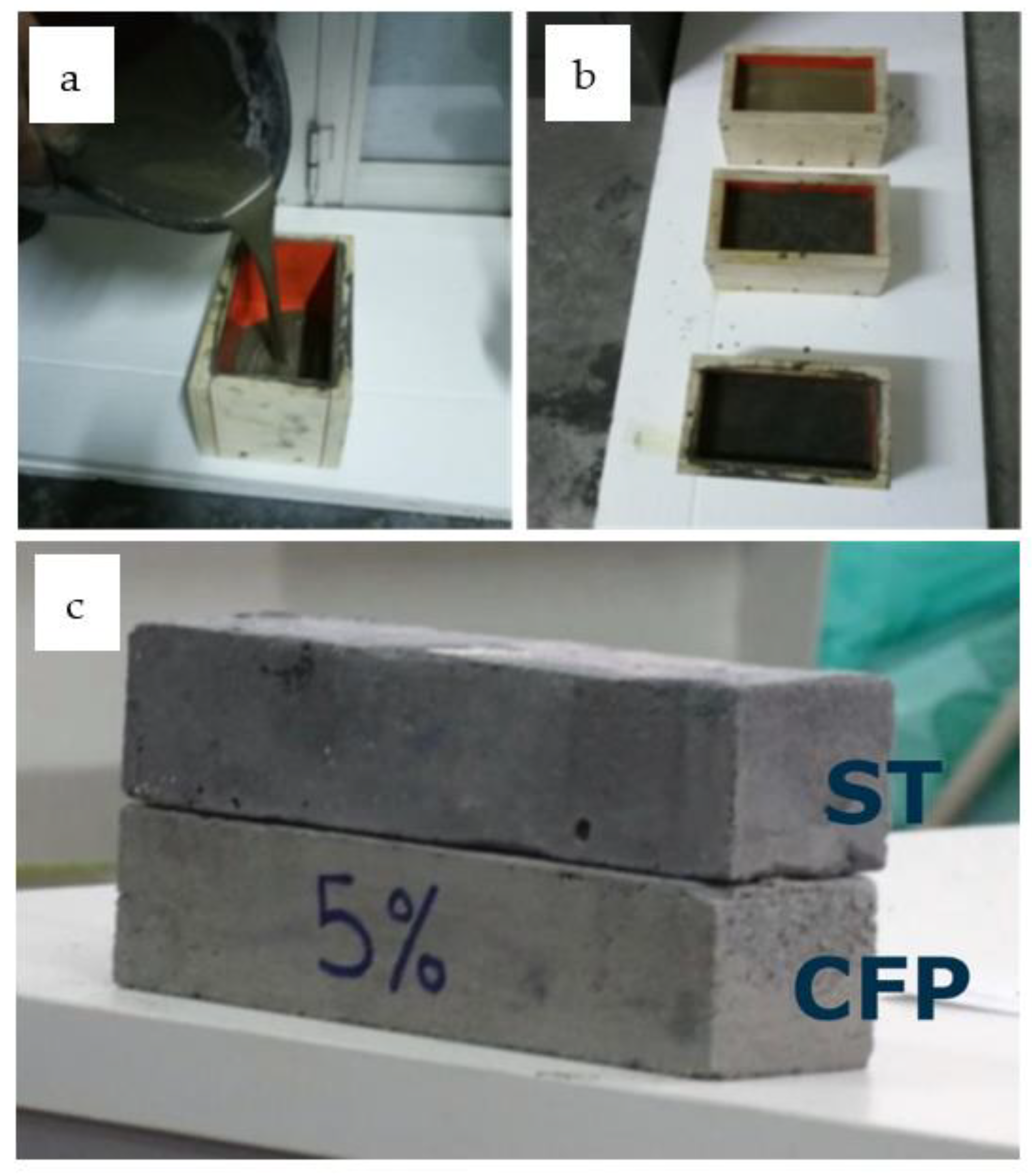
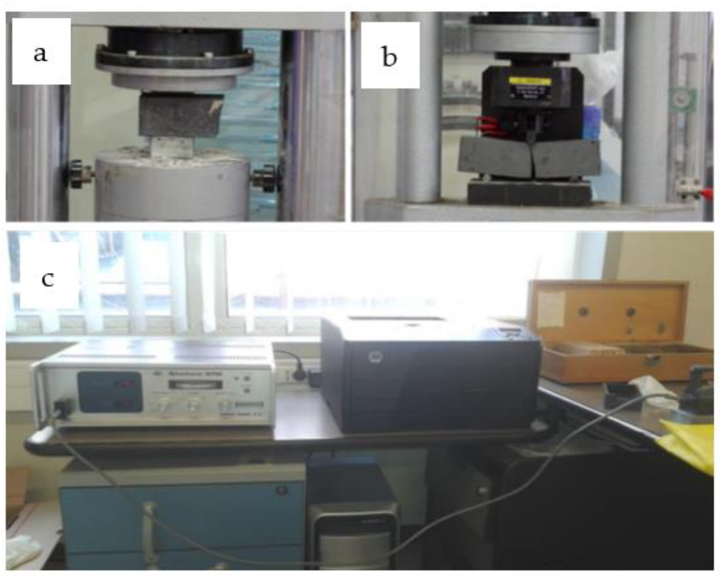
2. Materials and Methods

The performance of the GSHP system generally depends on several aspects in which the ground heat exchanger plays an important role. Borehole space fills often use pure or mixed materials that influence heat transfer efficiency [13,14]. However, standard products often do not provide optimal heat exchange properties, and for this reason, new mixtures should be designed in order to guarantee optimal thermal exchange and efficiency of the entire geothermal system without interfering with the production costs. Solutions in this regard can include realization and sale cost not excessively high so that the final product can be proposed and placed on the market at competitive prices compared to products already present on the market. Although pure materials have no negligible cost [17], their purchase and/or use in a not completely pure form could certainly contribute to decreasing the final costs. In order to avoid high thermal resistances and to facilitate heat transmission, this study proposes the use of mixed grout with CF waste as an additive. The approach appears promising to enhance the thermal and mechanical response in geothermal probes installation [19,20]. The experimental tests have been run using a standard bentonitic grout already on the market as starting material. The grout mixture used is composed of sulfate-resistant cement according to European standards [21] with selected mineral substances. Concerning the declared properties: the bulk density of the standard grout ranges between 1.35 kg/dm3 and 1.79 kg/dm3, depending on the water/solid ratio used to prepare the mixture. The characteristic values for the commercial grout were determined with a high-speed mixer under laboratory conditions with a water/filling binder value of 0.44. Declared fluidity for 1000 mL of suspension is 45 s (Marsh Cone Test with nozzle of 10 mm following the normative for draining [22]). Regarding the mechanical property investigations, technical characteristics specified for the standard mixture report flexural strength ~2 N/mm2 and uniaxial compressive strength ~6 N/mm2 after 28 days (following the testing normative [23]) as well as thermal conductivity ≥2 W/mK. For the experimental mixture, the additive used is carbon fiber powder (hereafter CFP), composed of 60% of pure CF and 40% of resin. The CFP additive shows an estimated thermal conductivity >50 W/mK. Two different mixtures have been used for the mechanical and physical testing phase: (1) pure standard grout; (2) standard grout with 5% of CFP–doped grout. The preparation of the two solutions for the subsequent tests was performed by accredited laboratories according to the standards of [24]. Table 1 shows the proportions used for the different configurations and the conditions of temperature and humidity constantly monitored. Tests were conducted in two different phases: (1) mechanical property tests (uniaxial compressive strength and flexural strength tests); (2) thermal conductivity measurements. For the uniaxial compressive strength and flexural strength tests, automatic equipment has been used. The instrument is equipped with 4 reading channels and a digital dynamometer able to perform tests for compression, flexure, indirect tensile, paving blocks, breaking in load/deformation control, elastic module up to 999 cycles of loading/unloading for evaluations of creeping or ductility of various building materials. According to the UNI EN 196-1:2016 [24], the tests have been performed on 6 prepared samples of standard material and 6 of mixed grout (Figure 1) for uniaxial strength evaluation, and 3 prepared samples of standard material and 3 of mixed grout for flexural strength assessment. The samples have been used for uniaxial (Figure 2a) and flexural tests (Figure 2b), and the obtained measurements were divided as follows: (1) 2 uniaxial strength measurements after 14 days for each sample of standard and doped material; (2) 4 uniaxial strength measurements after 28 days for each sample of standard and doped material; (3) 1 flexural strength measurements after 14 days for each sample of standard and doped material; (4) 2 flexural strength measurements after 28 days for each sample of standard and doped material, as indicated in Table 2.
The uniaxial compressive strength (Rc) was obtained from the equation:
R c = F c a ·   b
where a and b set the surface of the auxiliary plates at 1600 mm2 (40 × 40 mm), while Fc is the maximum value of the load causing the collapse.
The flexural strength (Rf), also known as modulus of rupture, was obtained from the well-known formula of the linear elastic regime:
R f = ( 1.5 F f b 3 ) l
where l = 100 mm represents the distance between the supports; b = 40 mm coincides with the side of the square prism section. Ff is the maximum value of the collapse load measured during the test.
Concerning the second step, experimental determinations of thermal conductivity have been conducted in collaboration with the Technical Physics Lab of the University of Catania by means of a heat flow meter. The measurement process has been performed with a non-stationary hot wire method according to the standards of ASTM E 1530 [25]. The test lasted 180 s (60 s on average) after the heating wire reached the operative temperature condition (temperature < 20 °C in 45 min). During the heat transfer process from the instrument to the sample, the temperature increase is lower than 20 °C without changes in the material properties during tests [14,26,27]. The use of high thermal conductivity materials such as CF mixture results in a good thermal efficiency and improvement of the mechanical and hydraulic qualities such as high shrinkage, waterproof, long-lasting and frost-proof for the insulating of the probe.

3. Results

In this study, we have performed physical-mechanical and thermal tests on standard bentonite grouts and doped grouts with 5% CFP. On the experimental samples, uniaxial compressive and flexural tests were performed, investigating the material response after 14 days and 28 days from sample preparation.

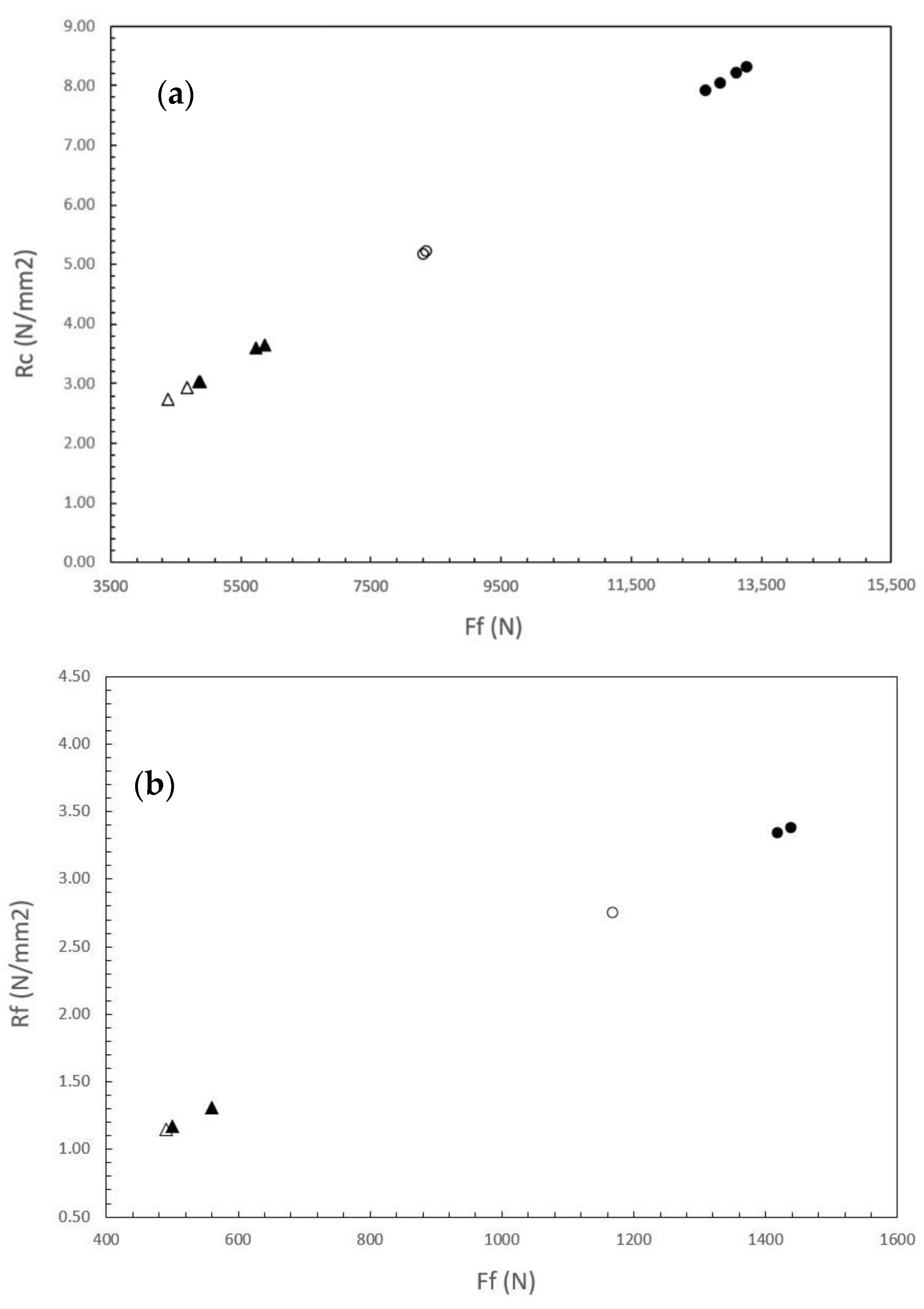
3.1. Compressive Strength Test

The results of the compressive strength tests performed on standard and doped materials are reported in Table 2.
Results in Figure 3a show the significant increase in the breaking load of material with CFP. On the sample at 14 days, we observed an increase of about 84% in uniaxial compression, namely from 2.83 N/mm2 (standard material) up to the value of 5.22 N/mm2 for the doped sample. On the sample at 28 days, a significant increase from 3.33 N/mm2 to 8.11 N/mm2 has also been observed.

3.2. Flexural Strength Test

The values obtained from the flexural strength tests (Ff) carried out on the different grout are reported in Table 3.
As for the uniaxial compression, the tests also show an increase in flexural strength between two configurations. Measurement on the sample as it is at 14 days, the material with additives shows an increase in the strength point from the value of 1.15 N/mm2 and a value of 2.74 N/mm2 for the sample with additives; at 28 days, it is possible to observe a similar adaptation and an increase on average on two measurements performed from 1.24 N/mm2 to 3.35 N/mm2 (Figure 3b).

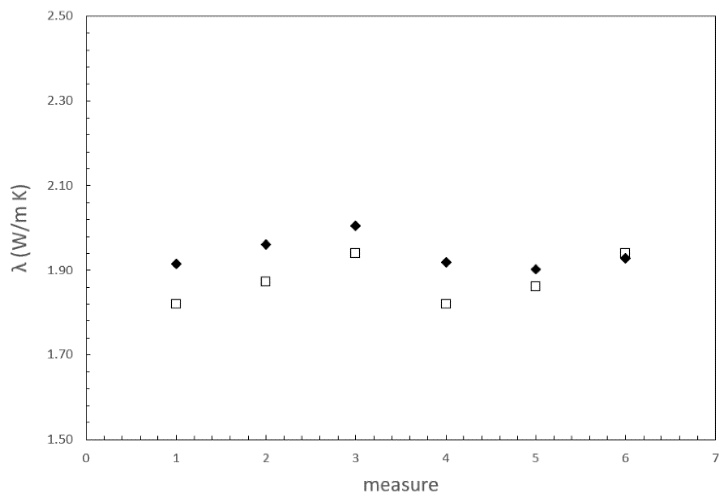
3.3. Thermal Conductivity Tests

In this case, we have performed 6 measurements on the standard and doped samples. The values obtained from the thermal conductivity measurements on the standard material confirm values as declared in technical specifications (values of λ > 1.00 W/m K). Table 4 displays slightly higher values of thermal conductivity compared to the declared values on the technical data sheet of the commercial grout. Concerning the average values on 6 measurements, an increase has been observed from a value of 1.88 N/mm2 (ST sample) compared to a value of 1.94 N/mm2 (CFP doped sample) with an increase of 3.4%.

4. Discussion

Results obtained in this work illustrate how waste materials such as CFP can reenter the manufacturing cycle as raw material and be reused in shallow geothermal systems, improving the mechanical and heat exchange characteristics of the filling grouts. The re-use of these materials allows not only the improvement of the heat exchange efficiency in closed-loop systems but also the reduction of industrial waste. Although the thermal performance of the GSHP system is primarily a function of materials, configuration of probes and the external heat pump, also the grout material filling the space between borehole and probe plays an important role [13,14]. Based on the results obtained by [28] using CFP as an innovative compound for the design of the geothermal probes, which improves the heat exchange between probe and soil, the utilization of thermal properties provided by CFP can be applied to the hybridization of filling grout.
In particular, results highlight the significant improvement of both compressional and flexural strength properties. In detail, it is possible to observe an improvement of about 84% (on average both in regards to a first step at 14 days and an even more significant improvement trend for the analyses performed at 28 days), as shown in the graph in Figure 3a shows. As for the compressive strength, a similar trend is displayed by the flexural strength with significant improvement between the standard and innovative material. The differences between the first (14 days) and the second step (28 days) of measurement could be related to the reduction of water percentages in the samples. Indeed, minor water contents could increase the strength of the sample.
Implications linked to the improvement of the mechanical characteristics through the addition of CFP in grout used in low enthalpy geothermal systems allow obtaining resistance properties useful for accommodating any stresses and guarantee excellent water-resistant properties of the compound in order to eliminate problems associated with leaks of heat transfer fluid resulting in high environmental quality standards material.
The thermal conductivity analysis has also highlighted an evident improvement in the thermal exchange characteristics, as shown in Figure 4. In fact, an improvement of about 3% on average was obtained, with the only exception of the last measured values, attributable to a greater presence of pores or to the presence of greater quantities of resin that decreased the heat exchange capacity by acting as an insulator.
The thermal conductivity improvement suggests that CFP, even in small percentages (5%), can enhance the heat exchange, becoming a good material for the sustainability of the initial investment.

4.1. Implication on Boreholes Dimensioning

Considering the standard normative of ASHRAE (American Society of Heating, Refrigerating and Air-Conditioning Engineers) based on studies of [29,30], the calculation of boreholes length in cooling (Lc) and heating configuration (Lc) could be reduced by acting on the parameter Rb regarding the thermal resistance, in the following Equation (3):
L c / h = Q a R g a + Q g   c / h ( R b + ( P L F m R g m ) + R g d F s c ) T g [ ( T w i T w 0 2 ) ] c / d T p
where Qa is the average heat flux exchanged during 1 year (expressed in W); Rga is the equivalent thermal resistance per length unit of the ground (annual pulse, expressed in m K/W); Qg c/h is the project load at the ground side during the heating (h positive value) and cooling (c negative value) seasons (expressed in W); Rb is the equivalent thermal resistance per length unit of the heat exchanger, corresponding to the thermal exchange between the heat transfer fluid and the borehole surface (expressed in m K/W); PLFm is the monthly part load factors; Rgm is the equivalent thermal resistance per length unit of the ground (monthly pulse expressed in m K/W); Rgd is the equivalent thermal resistance per length unit of the ground (daily pulse expressed in m K/W); Fsc is the loss factor due to possible thermal short-circuits in the exchanger between input/output pipes; Tg is the ground temperature (expressed in °C) not disturbed by the exchanger; Twi and Tw0 is the input and output average temperatures (expressed in °C) of the transfer fluid during the heating and cooling seasons; Tp is the penalty temperature (expressed in °C), which evaluates the interference between exchangers. The borehole thermal resistance Rb can be calculated through several methods. One of the most adopted was proposed by [12]. Assuming a conventional design of the thermal exchange system (borehole and probe diameters), the results presented in this work demonstrate the effect of the changing thermal conductivity of grout in the computation of Rb for: (1) standard probe plus standard grout; (2) standard probe plus innovative grout (5% CFP); (3) innovative probes from [28] plus innovative grout (5% CFP).
Considering the equation:
R b = R p + R g r
where
R p = L p A p λ p
R g r = 1 S b λ g r
where Lp refers to the thickness of probe, Ap refers to the area perpendicular to heat flow (expressed in m2) for the probe, and it is obtained from the relation 2πrh, where r is the probe radius (m), h is the depth (m); λp is the thermal conductivity of the probe (expressed in W/mK), Sb is the short-circuit factor and λgr is the thermal conductivity of the sealing grout (expressed in W/mK).
Concerning the short-circuit factor (Sb), it can be calculated as follows:
S b = β 0 ( d b D p o ) β 1
where β0 and β1 are coefficients depending on the geometry of input/output pipes into the borehole [12], whereas db and Dpo are the borehole (expressed in m) and the pipe (i.e., the probe diameter) diameter (expressed in m). In changing the λgr parameters, the impacts on the total sizing of the low-enthalpy geothermal installation can be therefore assessed in terms of borehole length Equation (3). Indeed, also small variations of the thermal conductivity of the sealing material affect the total heat exchange between the subsoil heat and the geothermal system. Assuming the geometry of the probe pipes, borehole and probe dimension, and a homogeneous subsoil, changes of λgr from 1.82 W/m K (standard grout) up to 2.01 W/m K (innovative CFP grout) can reduce the final Rgr from 0.08 m K/W down to 0.07 m K/W (Table 5). Although few variations of Rb parameter were observed, an important effect in terms of total borehole length can be obtained (Lc/h Equation (3)). From Equation (4), decreasing the thermal resistance of the probe Rp and grout Rgr results in a decrease of 38.5% of the total resistance Rb using the innovative configuration (innovative CFP grout (this study) plus innovative CFP probe from [28]) compared to the standard configuration. Decreasing the equivalent thermal resistance Rb due to the increase of thermal exchange has important effects on the configuration of the SGS system. Indeed, considering Equation (3), a simple calculation to derive Lc/h was done by comparing the different configurations. As an example, a geothermal field made of vertical probes (BHEs) for a residential building complex requiring heating and free cooling was analyzed. The field consists of double U-tube BHEs with a 32 mm diameter pipe, a total BHE diameter of 156 mm and a length of 100 m. Concerning the thermal properties of the soil, the thermal conductivity of 2 W/mK was considered. Table 6 shows the parameters used to calculate the optimal sizing of the geothermal system. From the ASHRAE approach [30,31]. Equation (3), a total length reduction of 600 linear meters is obtained by using the innovative grout and probe CF material system compared to standard grout and standard probe (from 42 BHEs to 36 BHEs—Table 7). This implies a higher economic benefit due to the reduction of the total borehole length in terms of drilling costs or the number of probes to be installed. Indeed, an increase in thermal conductivity results in the optimization of the entire system and therefore provides the same thermal output with a shorter geothermal vertical probes system.

4.2. End of Waste and Economical Implication on Geothermal Applications

Considering the “end of waste” and the subsequent circular economy perspective, it is essential to evaluate how the process of reusing CFP waste from industrial processes can be recovered in the geothermal sector by improving the properties of the filling grout. As previously described, CFP innovative grout allows obtaining improvements in both mechanical and thermal characteristics by optimizing the physical properties and significant improvement of the heat exchange, respectively. One of the most innovative aspects of the reutilization of CFP in geothermal applications is related to the reduction of costs for the implementation of low enthalpy geothermal systems. In addition to the reuse of the CFP as production material instead of waste, the decrease in costs also includes the amount related to the reduction of linear meters of perforation, which represents a significant quota of costs of plant realization. By assuming an average value of 50 Euros per linear meter for perforation (geothermal field of about 40 probes), a cost reduction of about 35,000 Euros from standard to the innovative solution could be envisaged. Table 7 shows a simple analysis of the economic savings in the use of CFP composite materials applied to the example defined above. The use of CFP in the geothermal field guarantees the reuse of material that is an industrial waste for many industrial realities. Furthermore, since the disposal of CFP presents considerable costs, reuse becomes an applicable procedure that allows the CFP to re-enter the market as a raw material. Indeed, considering an amount of CFP of about 5 Kg per geothermal well, a total amount of 171 Kg is necessary for the geothermal field of the case study. In considering a total disposal price, there is a significant saving for companies that usually have to consider and dispose of CFP as waste material. Such savings results in profits since the companies must necessarily re-market CFP as a by-product to be resold. At the same time, commercial grout material producers will be able to make savings, as the cost of CFP is still low compared to the market price of grout material. Although, to date, no common price lists regarding the costs of the CFP are widely spread, in the example treated, an indicative cost of 0.10 cents/kg is considered. Table 8 illustrates the differences in terms of economic impact for the construction of both standard and innovative geothermal plant solutions. Analyzing the overall economic impact (costs and savings in charge to stakeholders in the production chain) and the real economic cost for the geothermal system realization, a saving of approximately 10% is still evident for the realization of a geothermal field probe with an innovative system. Furthermore, by analyzing the costs and savings concerning the non-disposal of CFP, it is clear that supporting a green and circular economy and end-of-waste policies are accompanied by material savings also due to the lack of expenditure connected to disposal of the CFP as a waste. Due to the large variability and the lack of an official pricing list of the waste disposal cost among the European countries, an average value of the Italian cost for waste disposal procedures has been considered in order to maintain geographical conformity on prices for materials used in the experiments. The adopted value is therefore based on the consultation of several specialized Italian companies and administrative local fixed fees, which are 0.50 Euro/Kg for the waste material and about 300 Euros of administrative costs.

5. Conclusions

The study illustrates the results of the experimental tests on mechanical and thermal properties of standard and enhanced bentonitic grouts for geothermal purposes. The experimental results reveal the suitability of industrial waste materials such as CFP for the improvement of mechanical and physical characteristics of geothermal grout. The analyses show significant improvements in enhanced grout with 5% CFP compared to the standard material currently on the market. In detail, improvement of 81% in flexural strength and 187% in compressive strength, as well as an increase of thermal conductivity by 3.5%, are observed. Regarding the improvements of thermal properties, the enhanced grout results in a very eligible mixture for use as sealing grout into probes installations for GSHP systems. The optimization of the obtained grout mixture for renewable installations such as low-enthalpy geothermal systems leads to an exponential increase in the efficiency of geo-probe systems and subsequent environmental benefits. Both financial and ecological benefits are easily demonstrated by results obtained with the application of the described methodology. The overall economic impact and the real economic cost for the geothermal system realization, a saving of approximately 10%, is still evident for the realization of a geothermal field probe with an innovative system. In this regard, the development of a supply chain of new materials is following sustainable growth and represents a circular business model in the industrial CF production processes as well as innovative management for the achievement of the “End of Waste” model promoted by EU policies.

Author Contributions

G.F., S.U. and M.V. conceived and drafted the work; G.F., M.V. and G.M.B. conceived and designed the experiments; G.M.B. performed the experiments and G.F. and S.U. analyzed the data. M.V. gave the final approval of the version to be published. All authors have read and agreed to the published version of the manuscript.

Funding

This work was supported by the funding program PIACERI 2020-22 of the University of Catania (project code 22722132140; principal investigator M.V.).

Institutional Review Board Statement

Not applicable.

Informed Consent Statement

Not applicable.

Data Availability Statement

Not applicable.

Acknowledgments

The authors are grateful to the staff of EarTherm laboratories for providing an opportunity to design and build the innovative solutions and for recording the mechanical and thermal data of the grout.

Conflicts of Interest

The authors declare no conflict of interest.

References

  1. Langsdorf, S. EU Energy Policy: From the ECSC to the Energy Roadmap 2050; Green European Foundation: Brussels, Belgium, 2011. [Google Scholar]
  2. Karlsson, C.; Silander, D.; Pircher, B. Smart, Sustainable and Inclusive Growth: Political Entrepreneurship for a Prosperous Europe; Edward Elgar Publishing: Cheltenham, UK, 2019; ISBN 9781788974080. [Google Scholar]
  3. Fetting, C. “The European Green Deal”, ESDN Report; ESDN Office: Vienna, Austria, 2020. [Google Scholar]
  4. European Commission. The European Green Deal. Communication from the Commission to the European, The European Council, The Council, The European and Social Committee of the Regions; European Commission: Brussels, Belgium, 2011. [Google Scholar]
  5. European Commission. An EU Strategy on Heating and Cooling. Communication from the Commission to the European, The European Council, The Council, The European and Social Committee of the Regions; European Commission: Brussels, Belgium, 2016. [Google Scholar]
  6. Lund, J.W.; Toth, A.N. Direct Utilization of Geothermal Energy 2020 Worldwide Review. Geothermics 2021, 90, 101915. [Google Scholar] [CrossRef]
  7. Banks, D. An Introduction to Thermogeology: Ground Source Heating and Cooling; John and Wiley and Sons: Hoboken, NJ, USA, 2012. [Google Scholar]
  8. Midttømme, K.; Banks, D. Ground-Source Heat Pumps and Underground Thermal Energy Storage: Energy for the Future. NGU Spec. 2008, 11, 93–98. [Google Scholar]
  9. Rybach, L. CO2 Emission Mitigation by Geothermal Development-Especially with Geothermal Heat Pumps. In Proceedings of the World Geothermal Congress, Bali, Indonesia, 25–29 April 2010. [Google Scholar]
  10. European Geothermal Energy Council. EGEC Geothermal Market Report, 2018, 8th ed.; EGEC: Brussels, Belgium, 2019; ISBN 9788578110796. [Google Scholar]
  11. European Geothermal Energy Council. EGEC Geothermal Market Report, 2019, 9th ed.; EGEC: Brussels, Belgium, 2020. [Google Scholar]
  12. Remund, C.P. Borehole thermal resistance: Laboratory and field studies. ASHRAE Trans. 1999, 105, 439. [Google Scholar]
  13. Mahmoud, M.; Ramadan, M.; Pullen, K.; Abdelkareem, M.A.; Wilberforce, T.; Olabi, A.G.; Naher, S. A Review of Grout Materials in Geothermal Energy Applications. Int. J. Thermofluids 2021, 10, 100070. [Google Scholar] [CrossRef]
  14. Viccaro, M. Doped Bentonitic Grouts for Implementing Performances of Low-Enthalpy Geothermal Systems. Geo-Therm. Energy 2018, 6, 4. [Google Scholar] [CrossRef] [Green Version]
  15. Indacoechea-Vega, I.; Pascual-Muñoz, P.; Castro-Fresno, D.; Calzada-Pérez, M.A. Experimental Characterization and Performance Evaluation of Geothermal Grouting Materials Subjected to Heating-Cooling Cycles. Constr. Build. Mater. 2015, 98, 583–592. [Google Scholar] [CrossRef] [Green Version]
  16. European Commission. Changing How We Produce and Consume: New Circular Economy Action Plan Shows the Way to a Climate-Neutral; Competitive Economy of Empowered Consumers: Brussels, Belgium, 2020. [Google Scholar]
  17. Naslain, R. Carbon Fibers From Pan and Pitch. In Advanced Inorganic Fibers: Process-Structure-Properties-Applications; Wallenberger, F.T., Naslain, R., Macchesney, J.B., Ackler, H.D., Wallenberger, F.T., Eds.; Springer: Boston, MA, USA, 2000; pp. 233–264. ISBN 978-1-4419-8722-8. [Google Scholar]
  18. Karaipekli, A.; Sari, A.; Kaygusuz, K. Thermal Conductivity Improvement of Stearic Acid Using Expanded Graphite and Carbon Fiber for Energy Storage Applications. Renew. Energy 2007, 32, 2201–2210. [Google Scholar] [CrossRef]
  19. Macias, J.D.; Bante-Guerra, J.; Cervantes-Alvarez, F.; Rodrìguez-Gattorno, G.; Arés-Muzio, O.; Romero-Paredes, H.; Arancibia-Bulnes, C.; Ramos-Sánchez, V.; Villafán-Vidales, H.I.; Ordonez-Miranda, J.; et al. Thermal Characterization of Carbon Fiber-Reinforced Carbon (C/C). Appl. Compos. Mater. 2019, 26, 321–337. [Google Scholar] [CrossRef]
  20. Zhang, X.; Fujiwara, S.; Fujii, M. Measurements of Thermal Conductivity and Electrical Conductivity of a Single Carbon Fiber. Int. J. Thermophys. 2000, 21, 965–980. [Google Scholar] [CrossRef]
  21. DIN 1164-11; Special Cement—Part 11: Composition, Specification and Conformity Evaluation for Cement with Short Setting Time. European Standards s.r.o.: Pilsen, Czech Republic, 2003.
  22. UNI 11152; Aqueous Suspensions for Injections of Hydraulic Binders—Characteristics and Test Methods. Ente Nazionale Italiano di Unificazione (UNI): Milan, Italy, 2005. (In Italian)
  23. DIN 18136:2003–2011; Soil—Investigation and Testing—Unconfined Compression Test. European Standards s.r.o.: Pilsen, Czech Republic, 2011.
  24. UNI EN 196-1:2016; Methods for Test of Cements—Part 1: Determination of Mechanical Strengths. Ente Nazionale Italiano di Unificazione (UNI): Milan, Italy, 2016.
  25. ASTM E 1530; Standard Test Method for Evaluating the Resistance to Thermal Transmission by the Guarded Heat Flow Meter Technique. ASTM International: West Conshohocken, PA, USA, 2019.
  26. Fukai, J.; Kanou, M.; Kodama, Y.; Miyatake, O. Thermal conductivity enhancement of energy storage media using carbon fibers. Energy Convers. Manag. 2000, 41, 1543–1556. [Google Scholar] [CrossRef]
  27. Lee, C.; Park, M.; Nguyen, T.B.; Sohn, B.; Choi, J.M.; Choi, H. Performance Evaluation of Closed-Loop Vertical Ground Heat Exchangers by Conducting in-Situ Thermal Response Tests. Renew. Energy 2012, 42, 77–83. [Google Scholar] [CrossRef]
  28. Floridia, G.; Blandini, F.; Iuculano, S.; Belfiore, G.M.; Viccaro, M. Innovative Solutions for Improving the Heat Exchange in Closed-Loop Shallow Geothermal Systems. Energies 2020, 14, 108. [Google Scholar] [CrossRef]
  29. Ingersoll, L.R.; Zobel, O.J.; Ingersoll, A.C. Heat Conduction with Engineering, Geological, and Other Applications; University of Wisconsin Press: Madison, WI, USA, 1954. [Google Scholar]
  30. Kavanaugh, S.P.; Rafferty, K.D. ASHRAE Ground-Source Heat Pumps: Design of Geothermal Systems for Commercial and Institutional Buildings; American Society of Heating, Refrigerating and Air-Conditioning Engineers: Atlanta, GA, USA, 1997. [Google Scholar]
  31. American Society of Heating, Refrigerating and Air-Conditioning Engineers. ASHRAE Handbook: Heating, Ventilating, and Air-Conditioning Applications; Tullie Circle, N.E., Ed.; ASHRAE: Atlanta, GA, USA, 2007; ISBN 9781933742144. [Google Scholar]
Figure 1. (a,b) Samples preparation and (c) standard and doped (ST with 5% of CFP) bentonitic grout samples.
Energies 15 05806 g001
Figure 2. (a) Uniaxial (Rc), (b) flexural compressive (Rf) strength tests and (c) thermal conductivity tests on the standard and doped (ST with 5% of CFP) bentonitic grout samples.
Energies 15 05806 g002
Figure 3. (a) Diagram reporting the uniaxial (Rc) and (b) flexural compressive (Rf) strengths at the fracture point for the standard and doped (ST with 5% of CFP) bentonitic grouts as a function of the load applied to the sample (Ff and Fc). Symbols are as follows: triangles for the standard grout; circles for the grout + 5% of CFP. Open symbols are for tests at 14 days, filled symbols for those at 28 days.
Energies 15 05806 g003
Figure 4. Diagram of the repeated measurements of thermal conductivity obtained on the standard and doped (ST with 5% of CFP) bentonitic grouts. Symbols are as follows: squares for the standard grout; diamond for the grout plus 5% of CFP.
Energies 15 05806 g004
Table 1. Components used for the preparation of the bentonitic grout mixtures with CFP as additive.
Component/Weight Pure Material Mixture
ST
Doped Mixture
CFP
Standard material1000 g950 g
CF material050 g
Water440 mL 440 mL
Table 2. Compressive strengths (Rc) at the fracture point obtained on the standard pure material and doped bentonitic grout (ST with 5% of CFP). Ff is the strength applied at the center of prismatic samples.
Pure Standard MaterialFf (N)Rc (N/mm2)
14 days43702.73
14 days46802.93
28 days48503.03
28 days48703.04
28 days58603.66
28 days57403.59
Standard Material + 5% CFPFf (N)Rc (N/mm2)
14 days83505.22
14 days82905.18
28 days12,6407.90
28 days12,8708.04
28 days13,1308.21
28 days13,2808.30
Table 3. Flexural strengths (Rf) at the fracture point obtained of the standard pure material and doped bentonitic grout (+5% of carbon fiber). Ff is the strength applied at the center of prismatic samples.
Pure Standard MaterialFf (N)Rf (N/mm2)
14 days4901.15
28 days5001.17
28 days5601.31
Standard Material + 5% CFFf (N)Rf (N/mm2)
14 days11702.74
28 days14203.33
28 days14403.37
Table 4. Thermal conductivity obtained from measurements on the standard and doped (ST with 5% of CFP) bentonitic grouts.
N of MeasurementsPure Standard Material
ST
Standard Material + 5% CF
λ (W/m K)λ (W/m K)
11.821.92
21.871.96
31.942.01
41.821.92
51.861.90
61.941.93
Table 5. Calculated thermal resistance (Rb) for a 250 m borehole filled with standard and innovative grout.
λgrout
[W/m K]
λprobe
[W/m K]
Rgrout
[m K/W]
Rprobe
[m K/W]
Rb_tot
[m K/W]
ST1.820.450.080.050.13
CFP 5%gr2.010.450.070.050.12
CFP_innovative2.011.300.070.010.08
ST = standard grout plus standard probe; CFP 5%gr = innovative CFP grout (this study) plus standard probe; CFP_innovative = innovative CFP grout (this study) plus innovative CFP probe from [28].
Table 6. Parameters for the geothermal field model following the ASHRAE approach.
STCFP 5%grCFP_Innovative
Qa (W)434043404340
Qh (W)158,000158,000158,000
Rb (mK/W)0.130.080.07
PLFm0.600.600.60
Fsc1.041.041.04
Tg (°C)141414
Tm (°C)444
Table 7. Dimensioning of the geothermal field (probes of 100 m length).
N° Vertical ProbesLinear Meters
ST system424200
STprobe + CFP 5%gr404000
CFP innovative system363600
Table 8. Global economy impact.
ST System
(Euro)
CF Innovative System (Euro)
CFP disposal cost4000
CFP cost018
Commercial Grout cost13021060
Cost of commercial Probe40,1730
Cost of innovative Probe (PE−100)046,486
Cost of geothermal perforation210,000180,000
Total amount251,875227,564
Publisher’s Note: MDPI stays neutral with regard to jurisdictional claims in published maps and institutional affiliations.

