
A Study on the Integrity Evaluation of Cement Sheaths for Deep Wells in Deep Water


Abstract
:1. Introduction
2. Evaluation Method of Cement Sheath Integrity in a Dual-Deep Well
2.1. Domestic and Overseas Research on the Integrity Evaluation of the Cement Sheath
2.2. Integrity Evaluation of the Cement Sheath
2.3. Development of a Cement Sheath Integrity Evaluation Test Device
2.3.1. Design Ideas
- Accurate wellbore simulation:
- 2.
- Error check:
- 3.
- Clear environmental variables:
- 4.
- Check device performance:
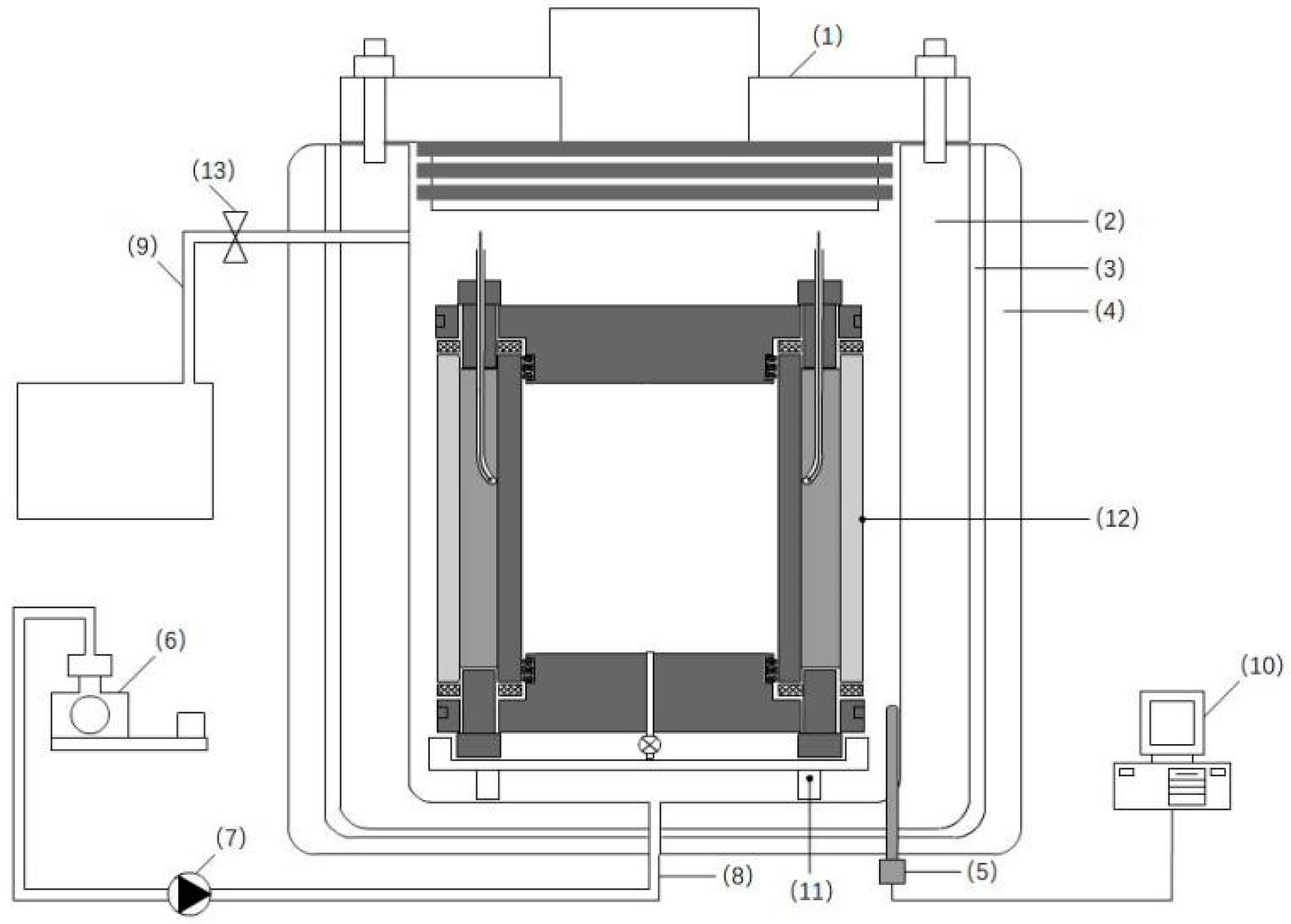
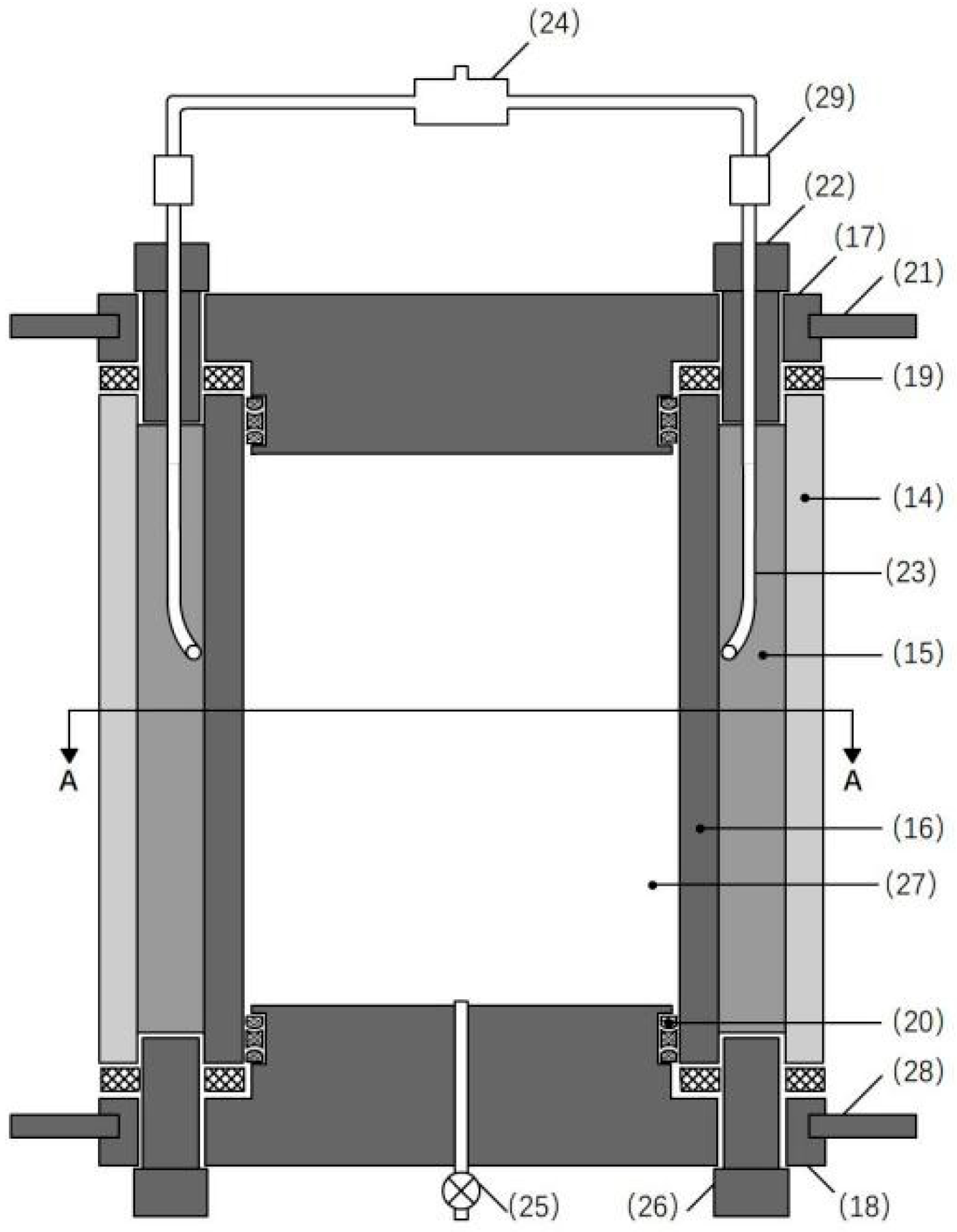
2.3.2. Device Introduction
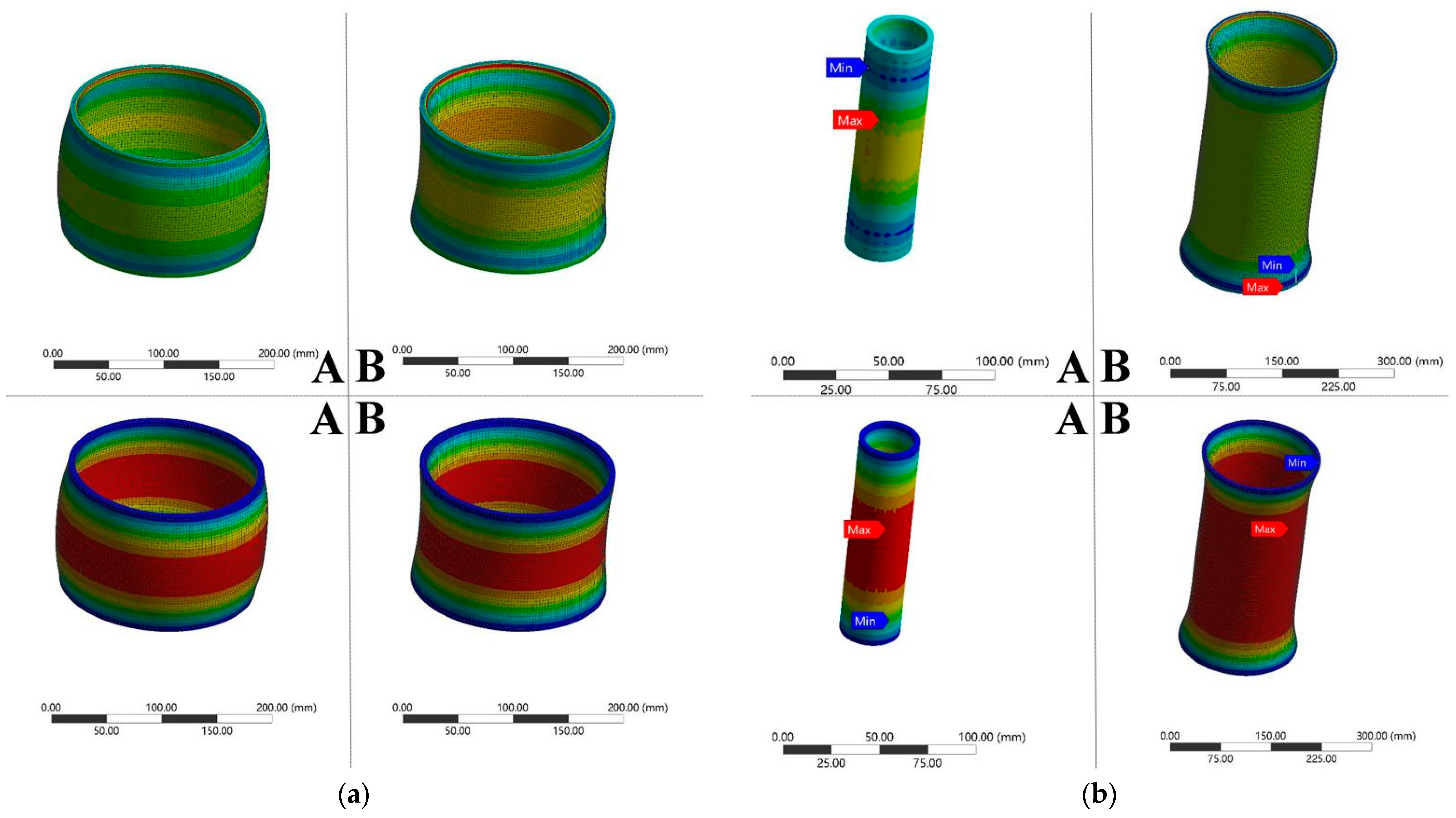
2.3.3. Installation Feasibility Verification
3. Experimental Study on Seal Integrity Evaluation of a Cement Sheath in a Dual-Deep Well
3.1. Basic Information of the Test
3.2. Integrity Test Evaluation Results
3.3. Study on Cement Sheath Seal Integrity Cement Slurry Performance Requirements
4. Microstructure Evaluation of Cement Sheath Integrity in a Dual-Deep Well
4.1. Microstructure Analysis Method
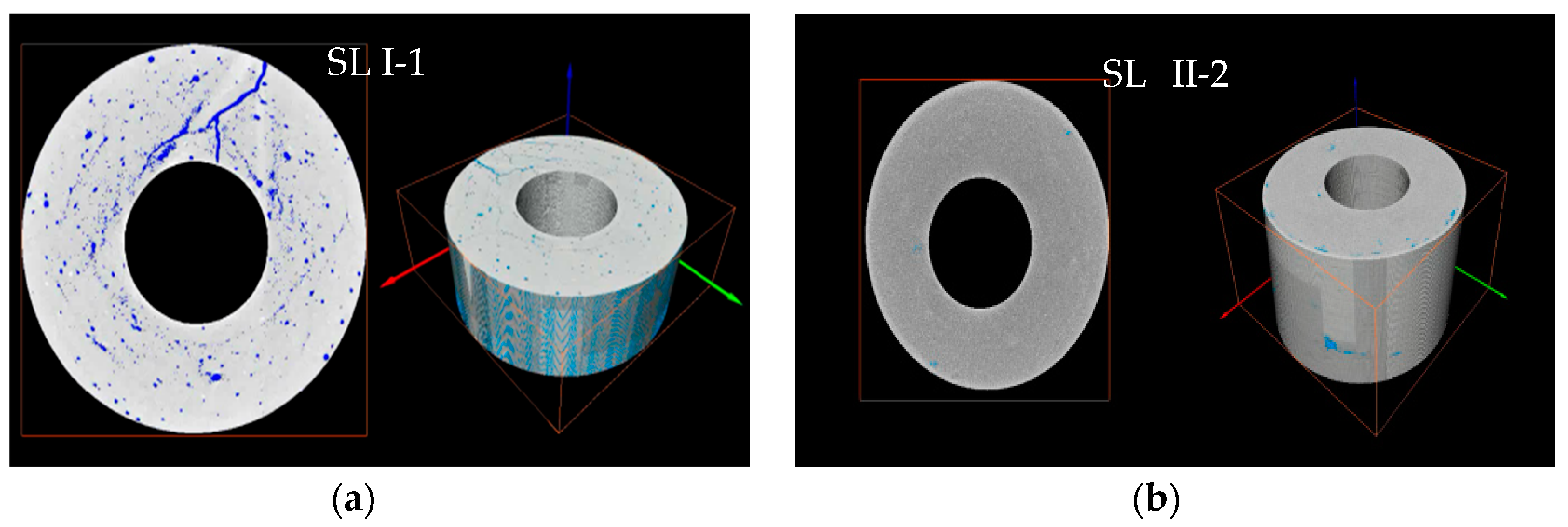
4.1.1. CT Scanning Analysis of Microstructure of the Cement Sheath
- Microstructure analysis
- 2.
- Analysis of interface characteristics
- 3.
- Pore extraction
- 4.
- Pore–throat analysis based on the maximum sphere algorithm
4.1.2. SEM Analysis of Microstructure of the Cement Sheath
4.2. Microstructure Evaluation and Analysis Results
- Microstructure analysis
- 2.
- Analysis of interface characteristics
- 3.
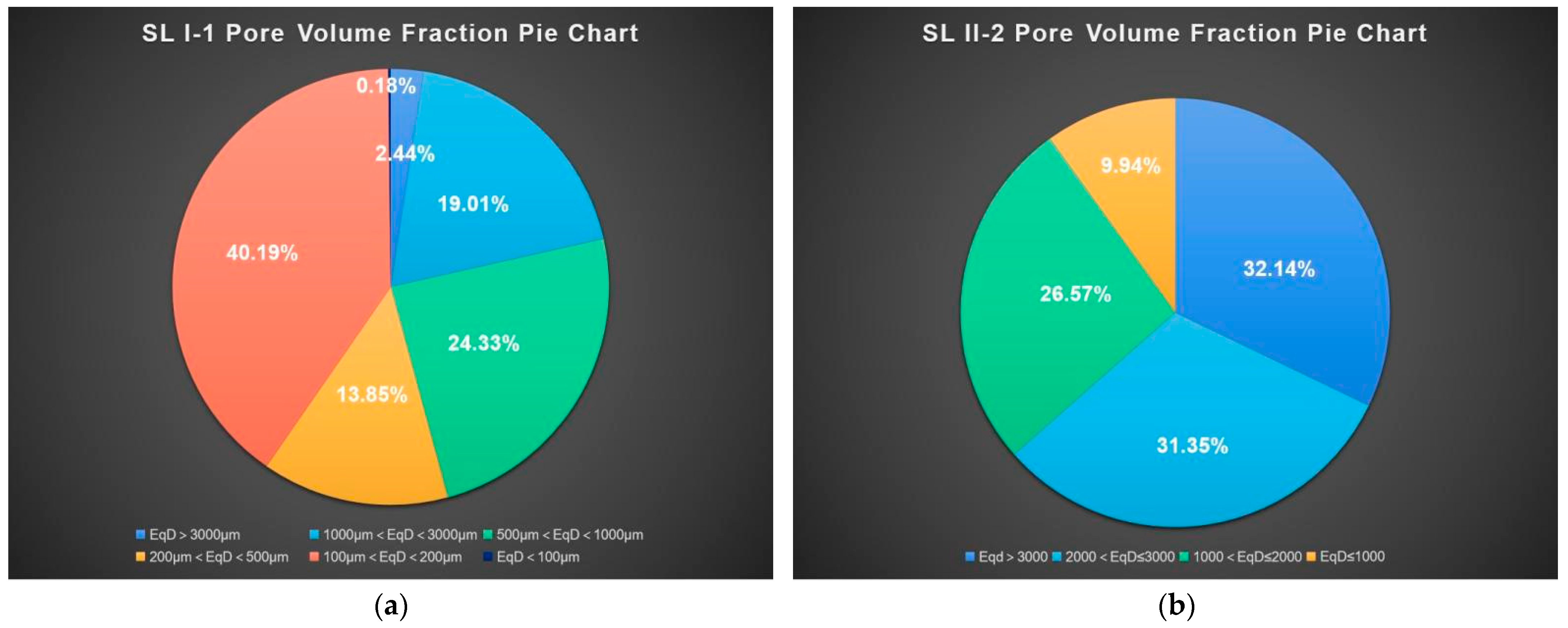
- Pore extraction/pore–throat analysis
- 4.
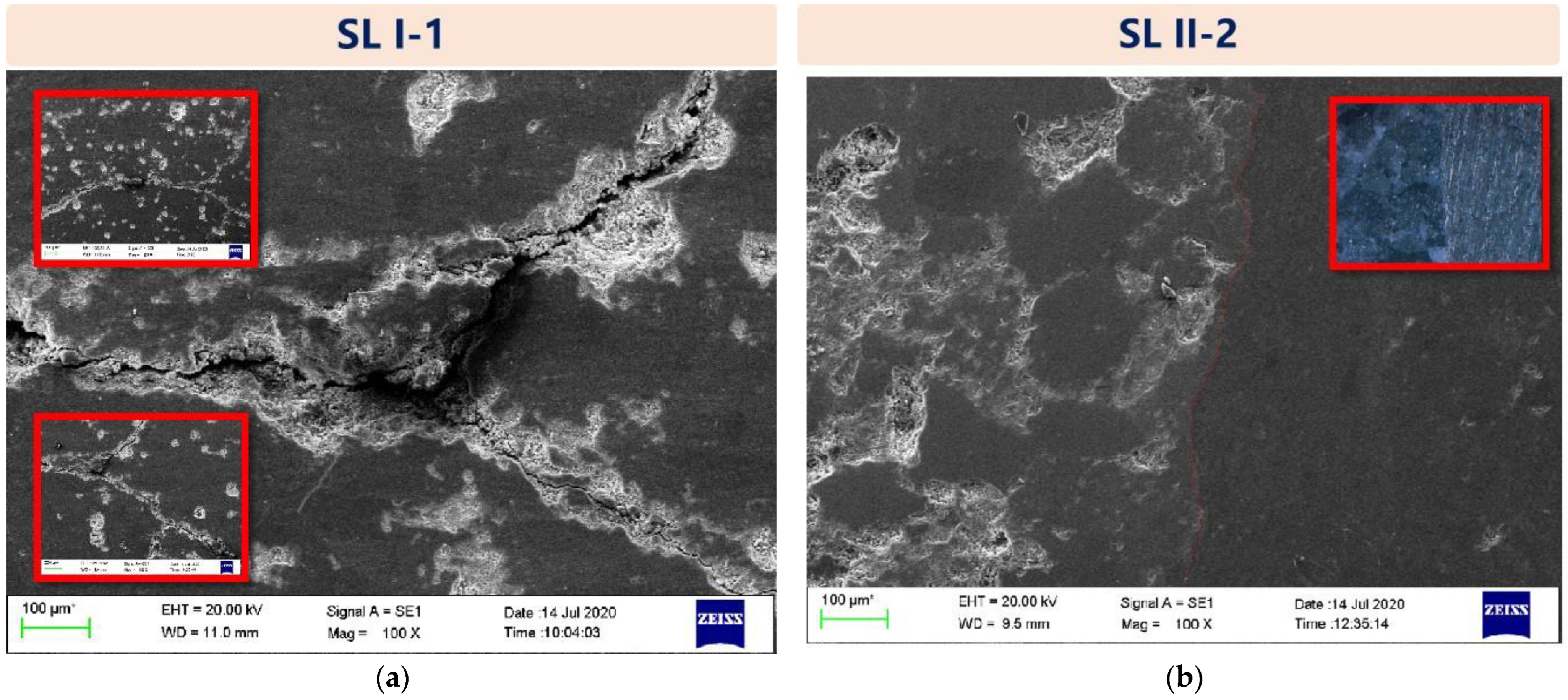
- SEM microscopic morphology analysis
4.3. Study on the Microstructure of Cement Sheath Seal Integrity
5. Conclusions
- A cement sheath seal integrity evaluation device suitable for a dual-deep well was developed.
- The isolation ability and sealing integrity of casing/cement sheath/formation assemblies prepared by five kinds of cement slurry systems were analyzed and evaluated. The experimental results show that on the basis of SD-G, C-DF64L as a defoaming agent, PC-F41L as a dispersant, C-FL80L as a water loss reducing agent, C-GR7 as an anti-gas channeling agent, C-R40L as a retarder, and PC-C82 as a heat stabilizer are optimized. The composite prepared has relatively excellent isolation ability and sealing integrity.
- The microstructure and morphology of composites with differing seal integrity were analyzed and evaluated. It is necessary to ensure sealing ability and seal integrity by strictly controlling the pore and pore throat of and cracks in the cement sheath.
- Future research can further study the cement sheath toughness/flexibility lifting technology, cement sheath performance degradation under deep-well high-frequency vibration, cement sheath quality testing technology, and seal integrity improvement measures.
Author Contributions
Funding
Institutional Review Board Statement
Informed Consent Statement
Data Availability Statement
Acknowledgments
Conflicts of Interest
References
- Wu, Z.Q.; Yue, J.P.; Li, Q.; Wu, Z.Q.; Geng, Y.N.; Liu, S.J.; Zhou, J.L. Experimental study on hydraulic seal integrity evaluation of cemented interface between casing and cement sheath. China Offshore Oil Gas 2018, 30, 129–134. [Google Scholar]
- Wu, Z.Q.; Liu, S.J.; Geng, Y.N.; Yue, J.P.; Zhou, J.L. Evaluation technology for isolation capacity of cement sheath in HTHP high-sulfur gas wells. Oil Drill. Prod. Technol. 2016, 38, 787–790. [Google Scholar]
- Li, Y.J.; Zhang, W.D.; Wu, J.; Yang, Y.H.; Zhang, G.S.; Yang, H.Q. Evaluation experimental study of isolation ability of cement sheath for HTHP gas well. Drill. Prod. Technol. 2020, 43, 23. [Google Scholar]
- Wei, Q. Research on Seal Integrity of Casing Cement Sheath in HTHP Gas Wells. Ph.D. Thesis, Southwest Petroleum University, Chengdu, China, 2019. [Google Scholar]
- Wu, J. Study on Sealing Integrity of Cement Sheath. Ph.D. Thesis, Yangtze University, Jingzhou, China, 2014. [Google Scholar]
- Geng, Y.N.; Qu, L.L.; Yue, J.P.; Huang, Z.Q.; Wu, Z.Q.; Zheng, S.J. Experimental study on the influence of cyclic load on the sealing integrity of cement sheath under complex temperature and pressure conditions. Miner. Explor. 2020, 11, 1066–1072. [Google Scholar]
- Lin, Y.H.; Deng, K.H.; Yi, H.; Zeng, D.Z.; Tang, L.; Wei, Q. Integrity tests of cement sheath for shale gas wells under strong alternating thermal loads. Nat. Gas Ind. 2020, 40, 81–88. [Google Scholar] [CrossRef]
- Wu, Z.Q.; Xing, X.J.; Fan, Z.L.; Cao, Y.F. Study on evaluation of hydraulic breakthrough capability in vertical direction of cementing seal system. J. Chongqing Univ. Sci. Technol. 2018, 20, 12–16. [Google Scholar]
- Liu, N.G.; Zhang, L.H.; Tao, Q.; Zhou, S.M.; Ding, S.D. Experimental study on airtightness of cement sheath under alternating stress. Drill. Fluid Completion Fluid 2016, 33, 74–78. [Google Scholar]
- Yang, Z.J.; Jiang, X.Q.; Wu, Z.Q.; Gao, L.; Zhu, H.T. Research on the simulation and evaluation experiment instrument for cementing integrity. Drill. Fluid Completion Fluid 2013, 30, 9–12. [Google Scholar]


| Name | SL I-1 | SL II-1 | SL II-2 | SL II-3 | SL III-5 |
|---|---|---|---|---|---|
| Cement | SD-G 50.37% | SD-G 46.74% | SD-G 46.97% | SD-G 46.44% | SD-G 47.2% |
| Thermal stabilizer | PC-C82 17.63% | C-Si80S 23.37% | C-Si80S 23.49% | C-Si80S 23.22% | TC-Si70S 23.61% |
| Water | 19.64% | 18.21% | 20.15% | 15.48% | 22.41% |
| Defoaming agent | PC-X66L 0.5% | C-DF64L 0.47% | C-DF64L 0.47% | C-DF64L 0.46% | PC-X61L 0.47% |
| Drop water loss | PC-G80L 1.81% | C-FL80L 1.87% | C-FL80L 3.28% | C-FL80L 1.39% | C-FL80L 3.07% |
| The gas channeling agent | PC-GR5 3.02% | C-GR7 8.41% | C-GR7 4.70% | C-GR7 12.07% | PC-GS12L 8.32% |
| Retarder | C-R40L 0.08% | C-R40L 0.93% | C-R40L 0.94% | C-R40L 0.93% | C-R22L 1.81% |
| Combination | The Surface State and Characteristics of the Combination | The Result of Channeling | Leakage and Seal Integrity |
|---|---|---|---|
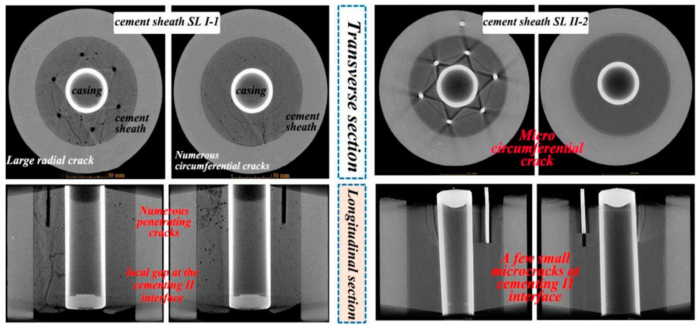
| SL I-1 | Numerous microcracks on the surface | The bubbles all originate from the crack site. | Complete channeling between the body, the cementing I interface, and the cementing II interface; loss of sealing. |
| SL II-1 | Body crack | The channeling pressure is only 0.55 Mpa, and channeling leakage occurs. | The body, the cementing I interface, and the cementing II interface are completely channeling, with almost no sealing. |
| SL II-2 | No obvious microcracks | There is no obvious leakage when the channeling pressure is 1 MPa, there is small channeling leakage when the pressure is 3 Mpa–5 Mpa, and there is discontinuous small channeling leakage when the pressure reaches 10 MPa, which can suppress the pressure. | There are small leakages between the cement body and the cementing I interface and between the cement body and the cementing II interface, which can contain pressure and provide a degree of seal integrity. |
| SL II-3 | Cracks on the surface of the body | There is no obvious leakage when the channeling pressure is 1 MPa, there is small channeling leakage when the pressure is 3 Mpa–5 Mpa, and there is discontinuous small channeling leakage when the pressure reaches 10 MPa, which can suppress the pressure. | There is leakage between the cement sheath body and the cementing I interface and between the cement body and the cementing II interface. Seal integrity is almost lost. |
| SL III-5 | Cracks on the surface of the body | At 1 Mpa–5 Mpa, discontinuous microbubbles appear in local areas, and discontinuous microbubbles appeared at 10 MPa. | There is a channeling between the cement sheath body and the cementing I interface and the cementing II interface, which has a certain degree of isolation ability. |
| Type of Admixture | Impact on Seal Integrity | Suggestions on Selection of Auxiliaries |
|---|---|---|
| Defoaming agent | The number and size of bubbles in the SL II-2 cement sheath were significantly reduced. The isolation capability and seal integrity are superior to that of SL I-1. | C-DF64L > PC-X66L C-DF64L dosage 1% |
| Dispersant | There was no aggregation of white additives in the upper part of SL I-1, and its dispersity was better than that of SL III-5. | PC-F41L > TC-F31L |
| Drop water loss | SL II and SL III-5 can resist certain test channeling pressure and the internal channeling is not complete; their sealing ability is superior to that of SL I. | C-FL80L > PC-G80L C-FL80L dosage 7% |
| The gas channeling agent | SL II series have a certain isolation ability, and their ability to inhibit gas migration and improve the isolation performance is superior to that of SL I series. | C-GR7 > PC-GR5/PC-GS12L C-GR7 dosage 10% |
| Retarder | The thickening time control of SL II and SL III-5 with C-R40L and C-R22L is more reasonable than that of SL I-1 with PC-H21L to achieve the best matching of early/late strength. | C-R40L > C-R22L > PC-H21L C-R40L dosage 2% |
| Thermal stabilizer | SL I-1 had better dispersion than SL II and SL III-5. No white additive was found in the high-temperature Cu sheath. | PC-C82 > C-Si80S PC-C82 dosage 50% |
Publisher’s Note: MDPI stays neutral with regard to jurisdictional claims in published maps and institutional affiliations. |
© 2022 by the authors. Licensee MDPI, Basel, Switzerland. This article is an open access article distributed under the terms and conditions of the Creative Commons Attribution (CC BY) license (https://creativecommons.org/licenses/by/4.0/).
Share and Cite
Wu, Y.; Zhou, J.; Yang, J.; Qin, W.; Zhang, T.; Wu, Z. A Study on the Integrity Evaluation of Cement Sheaths for Deep Wells in Deep Water. Energies 2022, 15, 5814. https://doi.org/10.3390/en15165814
Wu Y, Zhou J, Yang J, Qin W, Zhang T, Wu Z. A Study on the Integrity Evaluation of Cement Sheaths for Deep Wells in Deep Water. Energies. 2022; 15(16):5814. https://doi.org/10.3390/en15165814
Chicago/Turabian StyleWu, Yi, Jianliang Zhou, Jin Yang, Wei Qin, Tianwei Zhang, and Zhiqiang Wu. 2022. "A Study on the Integrity Evaluation of Cement Sheaths for Deep Wells in Deep Water" Energies 15, no. 16: 5814. https://doi.org/10.3390/en15165814
APA StyleWu, Y., Zhou, J., Yang, J., Qin, W., Zhang, T., & Wu, Z. (2022). A Study on the Integrity Evaluation of Cement Sheaths for Deep Wells in Deep Water. Energies, 15(16), 5814. https://doi.org/10.3390/en15165814