Article

Numerical Simulation of Oil Shale Retorting Optimization under In Situ Microwave Heating Considering Electromagnetics, Heat Transfer, and Chemical Reactions Coupling

1
State Key Laboratory of Shale Oil and Gas Enrichment Mechanisms and Effective Development, Beijing 100083, China
2
State Center Research and Development of Oil Shale Exploitation, Beijing 100083, China
3
Petroleum and Natural Gas Engineering, Southwest Petroleum University, Chengdu 610500, China
4
College of Chemistry and Chemical Engineering, Southwest Petroleum University, Chengdu 610500, China
5
Institute of Applied Electromagnetics, Sichuan University, Chengdu 610500, China
*
Author to whom correspondence should be addressed.
Energies 2022, 15(16), 5788; https://doi.org/10.3390/en15165788
Submission received: 8 July 2022 / Revised: 4 August 2022 / Accepted: 5 August 2022 / Published: 9 August 2022

Abstract

:
Oil shale constitutes an important proportion of unconventional resources, and its efficient exploitation helps alleviate the Chinese oil shortage situation. Nowadays, microwave heating is a promising method for in situ development of oil shale. However, the corresponding numerical simulation lacks in guiding the retorting optimization under microwave heating. A novel pseudo three-dimensional model, considering electromagnetics, temperature field, and chemical reactions coupling was developed and implemented to investigate oil shale reservoirs’ retorting performance under microwave heating based on the finite element method (FEM). The effects of microwave power, antenna number, and antenna position were analyzed creatively to optimize the microwave heating parameters. Numerical results showed high microwave power increased the maximum reservoir temperature quickly near the heating well, but the thermal conductivity of oil shale dominated the temperature of distal formation. For a typical case of two antennas at 0.9 m spacing and 500 W, the maximum temperature can reach 443 °C at 100 days, and the kerogen near the wellbore quickly converts to hydrocarbon products. Moreover, increasing antennas can improve the heating rate, and the specific distance between two antennas should be designed based on the microwave power and oil shale properties.

1. Introduction

With the shortage of traditional energy resources and the increasing oil demand, resolving the energy problem has become a big problem of urgency [1,2]. Hence, many countries have started to explore unconventional oil resources [3]. As a substantial proportion of unconventional oil and gas resources, oil shale is a fine-grained sedimentary rock rich in solid organic matter (kerogen) [4]. The oil shale reserves are enormous, storing up to 689 billion tons of shale oil. The United States has oil shale reserves of 530.5 billion tons, while China’s reserves are 47.6 billion tons [5]. As a significant substitutable fuel resource, the efficient and green development and utilization of oil shale are essential, significantly influencing China’s energy security and the strategic reserves of oil and gas resources [6]. As for the utilization method of oil shale, the retorting is more prevalent than directly burning as a fuel such as coal to generate electricity in power stations [7]. In the range of 400 °C to 500 °C at standard pressures, oil shale transforms into shale gas and liquid oil due to the decomposition of kerogen, in a transformation process for oil shale known in industry as retorting [8]. While oil shale retorting methods can be subdivided into surface retorting and in situ retorting, it is noted that surface retorting technology is harmful to the environment and inefficient, hence explaining the great focus of researchers on in situ technologies [9].
At present, many researchers are concentrating on the technology of oil shale in situ retorting to obtain shale oil and gas in many countries [10]. Kang et al. [11] investigated superheated steam injection for oil shale in situ pyrolysis and found this technology exceeded 95% oil-recovery rate in the pyrolysis area. Zhao et al. [12] proposed supercritical carbon dioxide (SC-CO2) as heat-carrying displacement to retort the oil shale reservoir and found the ingredient of aromatic hydrocarbon in shale oil increased under SC-CO2. Wang et al. [13] proposed using double-shell downhole electric heaters to reduce heat loss. Their results indicated the heating efficiency for oil shale retorting increased significantly due to the double-shell structure. While there are now many in situ retorting technologies, they are generally characterized by shortcomings such as high energy consumption, low heating efficiency, and inconvenient heating control.
A novel option that may hold potential for overcoming such issues is Microwave heating, based on its widespread use in other unconventional resources, including oil sands, heavy oil, and methane hydrate. Microwave heating has also been proposed to pyrolyze oil shale through both ex situ retorting and in situ retorting methods. Many laboratory experiment studies have proved its feasibility for retorting oil shale [14,15]. Under microwave irradiation, oil shale particles were converted into oil and gas in a short time [16]. The shale oil was more maltenic and had lower sulfur and nitrogen content than the shale oil obtained by conventional retorting [17]. Neto et al. [18] transformed oil shale using microwave heating and conventional stimulation and found that the overall energy requirements were much lower using microwave irradiation when the yields of liquid products were similar. He et al. [19] compared the microwave and conventional pyrolysis of oil shale and found that microwave heating provided higher average heating rates based on the same input power and higher weight loss at the same temperature compared with conventional pyrolysis. Compared with conventional heating, microwave pyrolysis decreased the activation energy by 13–39% and increased the reaction rate constant by at least 65%.
Although microwave has unique advantages in heating materials, it is challenging to apply experimentally in oil shale reservoirs. Numerical simulation based on high-performance workstations can be an effective tool to predict and evaluate the retorting performance of oil shale during heat treatment so that engineering parameters can be analyzed and optimized when applying microwave. Lee et al. [20] analyzed the effect of heating temperature, the spacing of hydraulic fractures and the position of horizontal production wells on the oil shale transformation during the in situ conversion process [21], Electrofrac [22], and Streamfrac, respectively. Peng et al. [23] established a two-dimensional model based on the FEM numerical model for microwave heating in shale reservoirs. The limitation of this study is considering Maxwell’s equation, mass conservation equation and energy conservation equation. Using a three-dimensional finite element model, Song et al. [24] coupled fluid flow, heat transfer, and chemical reactions to investigate the oil shale in situ conversion process. Xu et al. [25] performed coupled electromagnetic, heat transfer, and mechanical analysis in a three-dimensional geometry using the COMSOL Multiphysics software to investigate the microwave heating and degradation of hard rocks. The finite element model included electromagnetic wave radiation, thermal transfer, mechanical deformation, and damage evolution but was only applied to a laboratory setting that was not in situ. Zhu et al. [8] established a two-dimensional model to simulate the oil shale pyrolysis characteristic subjected to microwave irradiation. However, the three-dimensional model is also essential to reveal the spatial evolution law of electric field, reservoir temperature, and retorting products’ distributions. In summary, there are some remaining difficulties in researching the in situ retorting of oil shale under microwave heating by numerical simulation. The difficulties include the complex multiphysics relationship among many physical and chemical reactions, higher spatial dimensions of a physical model, and the design of antenna situation and number. Considering the demand for engineering applications, the retorting performance of oil shale reservoirs under microwave heating remains to be researched.
The objectives of this study are (1) setting up a numerical model considering electromagnetic excitation, heat transfer, mass transfer, and kerogen decomposition based on the oil shale in situ transformation under microwave heating; (2) investigating the effects of microwave power, antenna number and antenna position on the temperature distribution and retorting performance of a reservoir under microwave heating according to a multi-field coupling numerical model. This study is helpful to learn the mechanism of oil shale retorting under microwave heating, find the regulation between input parameters and retorting performance, and optimize the engineering parameters to obtain high economic benefits. Moreover, this work provides meaningful guidance for the application of microwave heating in unconventional resources development.

2. Mathematical Model

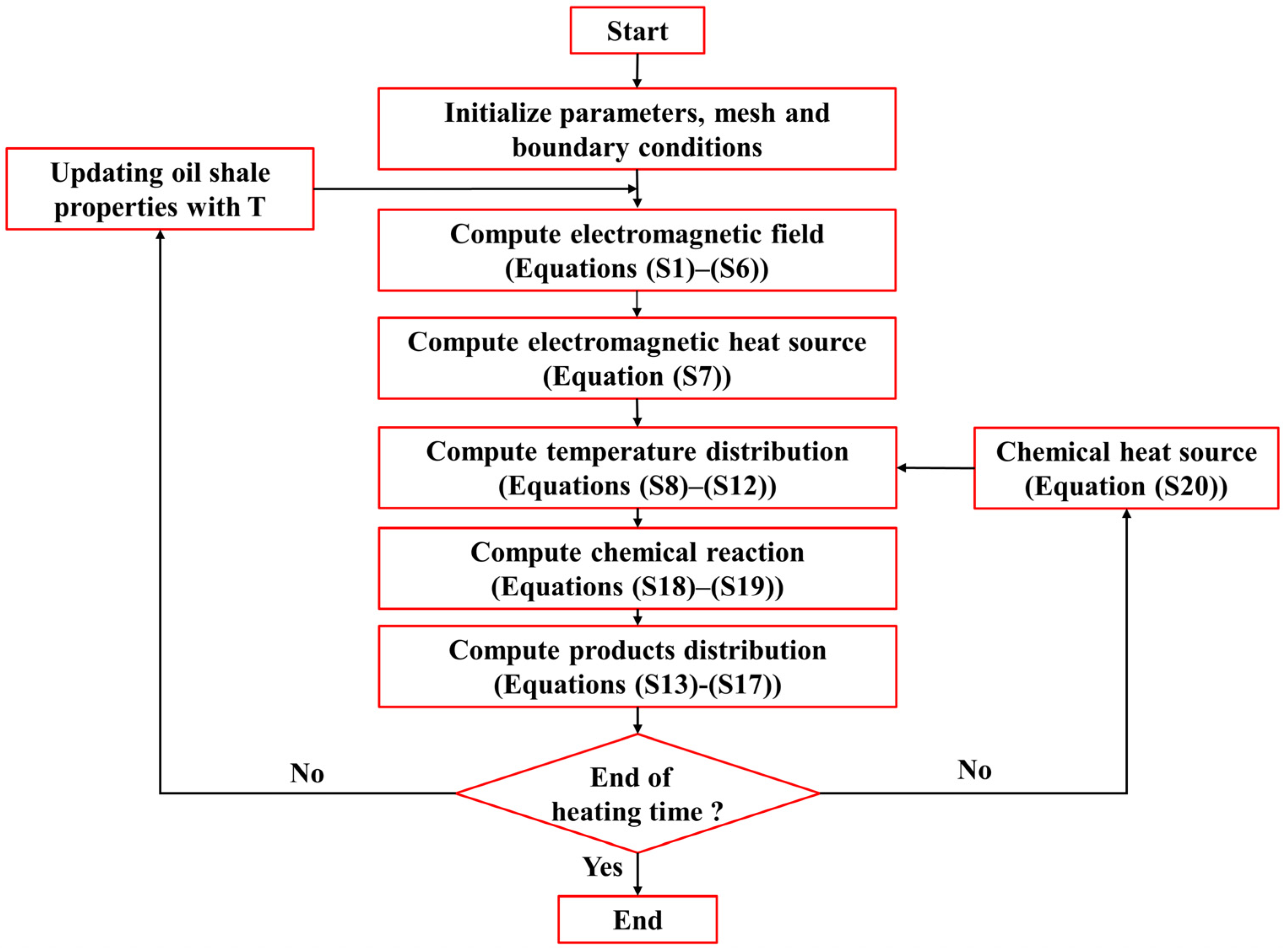
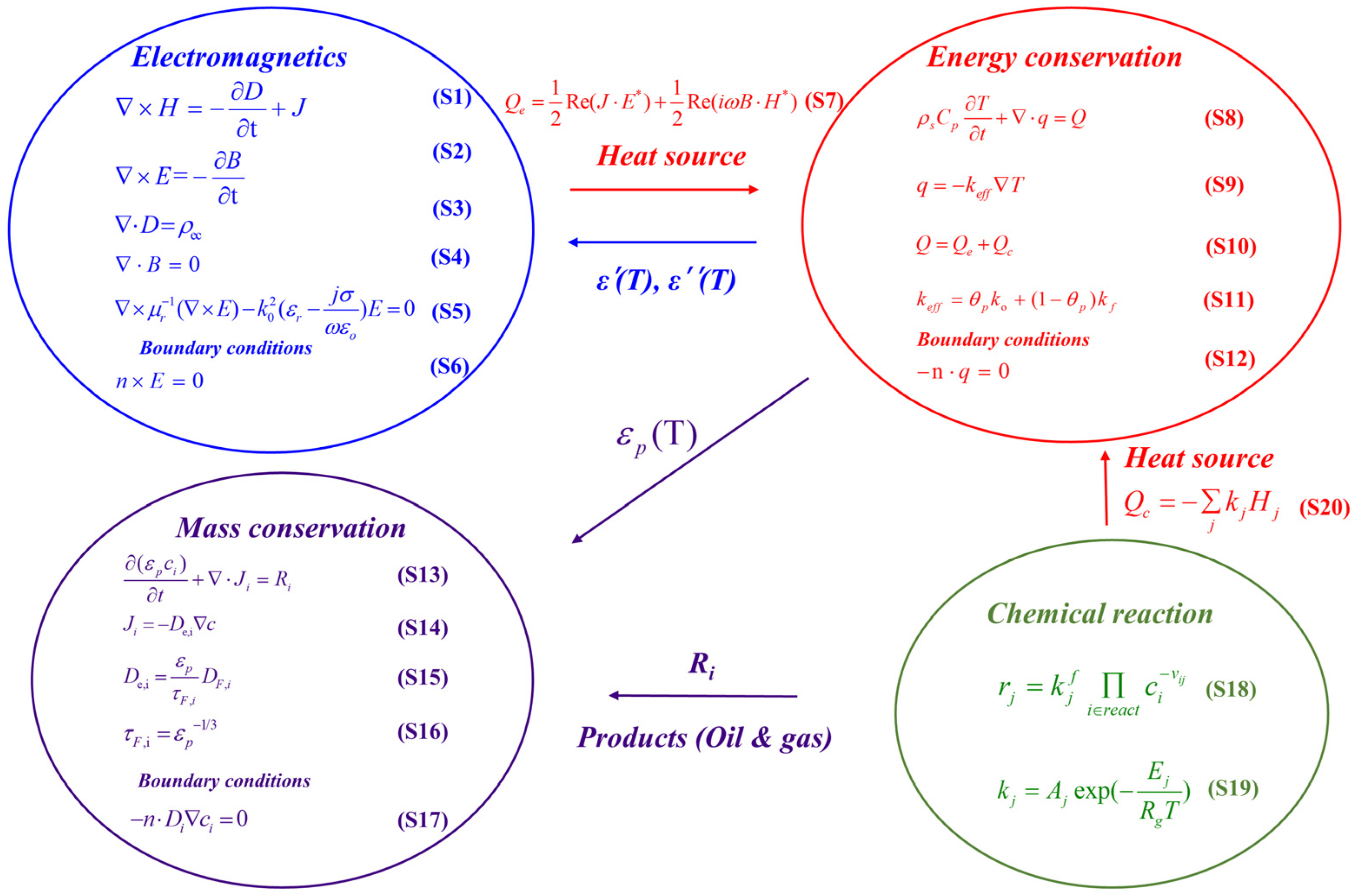
2.1. Multiphysics Coupling

The basis of the mathematical model is multiple physical and chemical processes, collectively described as multiphysics, that are coupled in the bulk phase and at the boundaries of the bulk phase by governing equations, boundary conditions, and constitutive relations. The multiphysics coupling process and corresponding relationships are depicted in Figure 1.

2.2. Electromagnetics

The time-harmonic electromagnetic field distribution within oil shale is obtained through the Maxwell’s Equations (Equations (S1)–(S5)). The heat source from electromagnetic excitation is calculated by Equation (S7). The temperature from energy conservation is coupled with electromagnetic physics through the temperature-dependent characteristics of the oil shale reservoir. The tube is assumed as the perfect electric conductor for setting the boundary condition (Equation (S6)).

2.3. Energy Conservation Equation

The energy conservation Equation (Equations (S8)–(S10)) is applied to describe the temperature distribution within the oil shale reservoir, which includes the energy convection by momentum conservation, heat conduction by temperature gradient, heat source from electromagnetic excitation (Equation (S7)), and exothermic reactions from kerogen decomposition (Equation (S20)). According to heat conduction, the effective thermal conductivity is calculated based on the volume fractions of the matrix and pore volume (Equation (S11)). The walls in the temperature transfer domain of the oil shale reservoir are considered as heat insulation conditions (Equation (S12)).

2.4. Mass Conservation Equation

In the oil shale reservoir, the mass transfer depends on diffusion and chemical reactions (Equations (S13)–(S15)). The diffusion of the products is dominated by the concentration gradient and tortuosity of porous media (Equation (S16)). The convection of the products is determined by the momentum conservation. The perforation location is taken as the outlet of the production well.

2.5. Chemical Reactions

All the chemical reactions, including kerogen decomposition and products cracking, are obtained by the first order rate law and Arrhenius Equation (Equations (S18)–(S19)). The heat from exothermic reaction is acquired by the enthalpy from all the chemical reactions (Equation (S20)). The chemical reactions based on the kinetic data are presented in Table 1. More details about equations can be found in the supporting information.

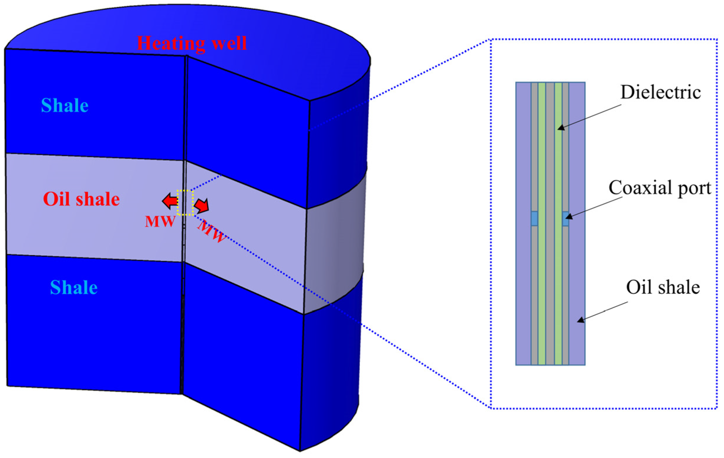
2.6. Model Description

As shown in Figure 2, a simplified pseudo three-dimensional model was built as a two-dimensional model with axial symmetry. The thickness of the model is 10 m, consisting of a central target oil shale formation that is 3 m in thickness, as well as top and bottom shale formations that do not feature kerogen decomposition.

2.7. Input Parameters

Under the high-temperature condition, the properties of oil shale vary with temperature. In this model, to simulate the in situ retorting process more accurately, all the properties of oil shale are considered to depend on the reservoir temperature, including density, specific heat [12], thermal conductivity in the vertical direction and horizontal direction, dielectric constant, loss factor [27], and porosity [3]. Table 2 shows the initial conditions and other parameters in this model. In addition, the ε′ of shale is 3 and the ε″ of shale is 0.2 [28,29]. Some specific parameters are shown in the supporting information. Moreover, the Peng–Robinson gas phase model was introduced to calculate the real-time properties of the mixture fluid.
Although temperature-dependent properties of oil shale are considered in the model, these settings can also increase the nonlinearity of the model during calculation. Before solving the mathematical model, some assumptions were made to simplify the model and save the calculation cost, including: (1) the formation is irradiated at a constant frequency of 2.45 GHz; (2) the phase change in water is negligible due to fast increasing reservoir temperature; (3) the flowing of decomposition products is considered as a single gas phase; and (4) microwave is excited by the coaxial port. Mapped meshing was used for the finite element model to solve these equations. Figure 3 shows the specific calculation process for this model. To accomplish the simulation, COMSOL Multiphysics 5.6 based on FEM was employed. Model development was verified by a grid-independent test to obtain accurate results. Based on that test, a mesh with 33,863 total mesh element number was used for the simulations, and all computations were performed in the same computer with an Intel Core i7-8750 processor and 32 GB random access memory.

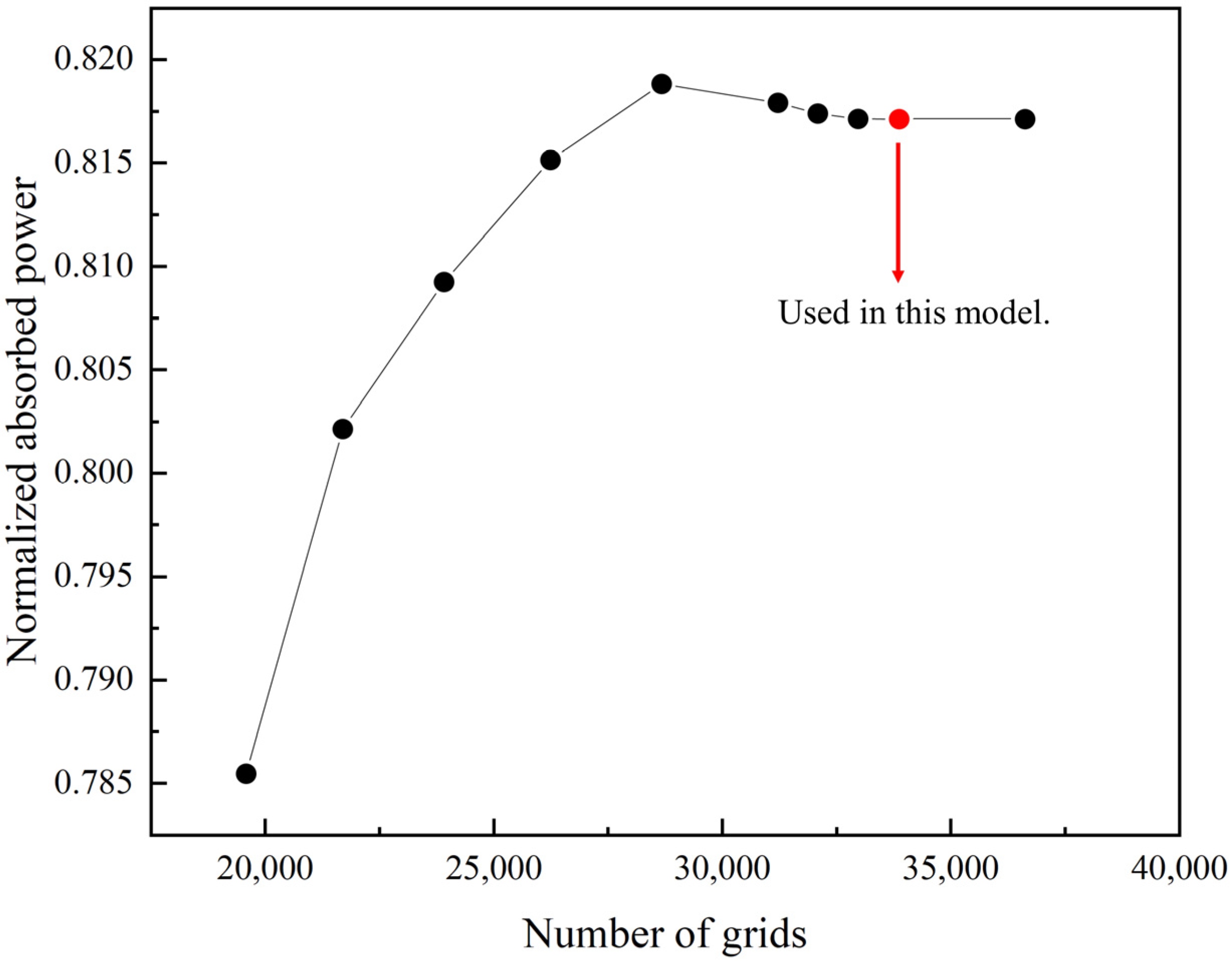
2.8. Grid Size Sensitivity Test

The mesh size has a significant influence on the convergence and accuracy of finite element analysis. To obtain accurate results, it is necessary to prove that the calculated values are independent of the grid size. The normalized absorbed power (NPA), which is defined as the ratio of the average simulated dissipated power in the lossy medium to the effective microwave power, is often used in a mesh-independent study [31]. When the value of NPA does not change with further refining of the time step, then the simulated temperature is considered to the time step. The NPA of the model under various finite mesh numbers is shown in Figure 4. When the grid number exceeds 33863 the NPA is nearly constant with a relative difference not exceeding 0.05% compared with that of the finer grid. The corresponding illustration about grid size sensitivity test was added in the manuscript.

3. Numerical Simulation

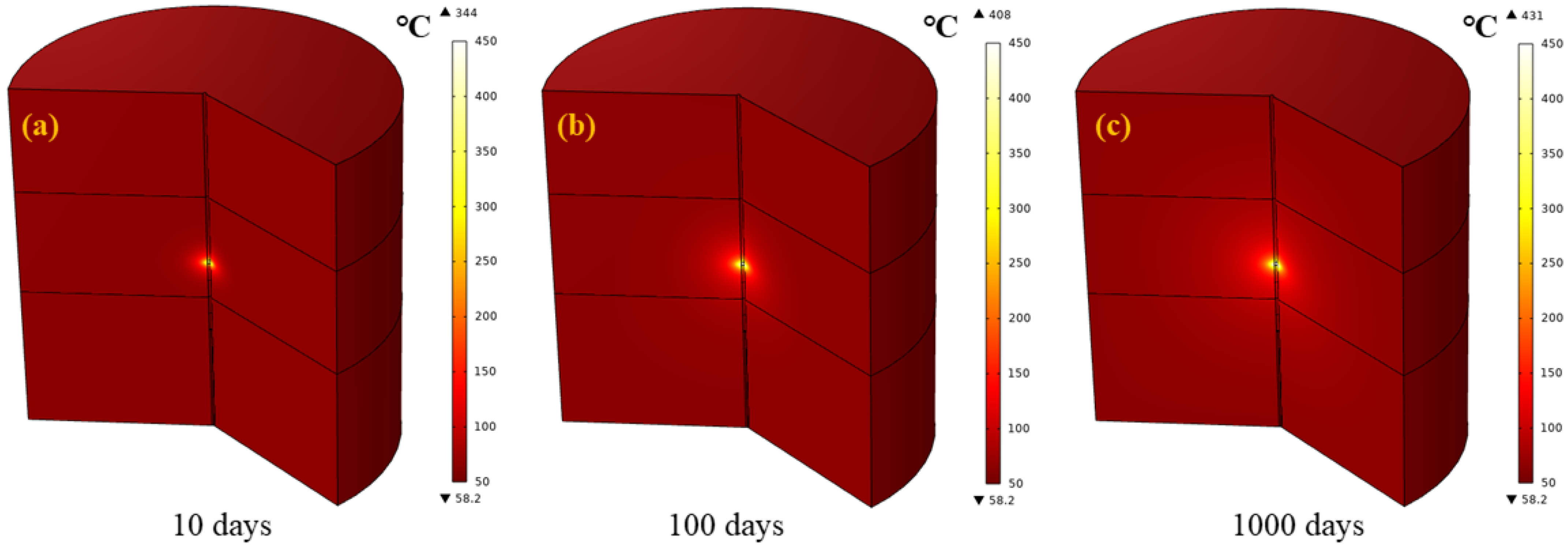
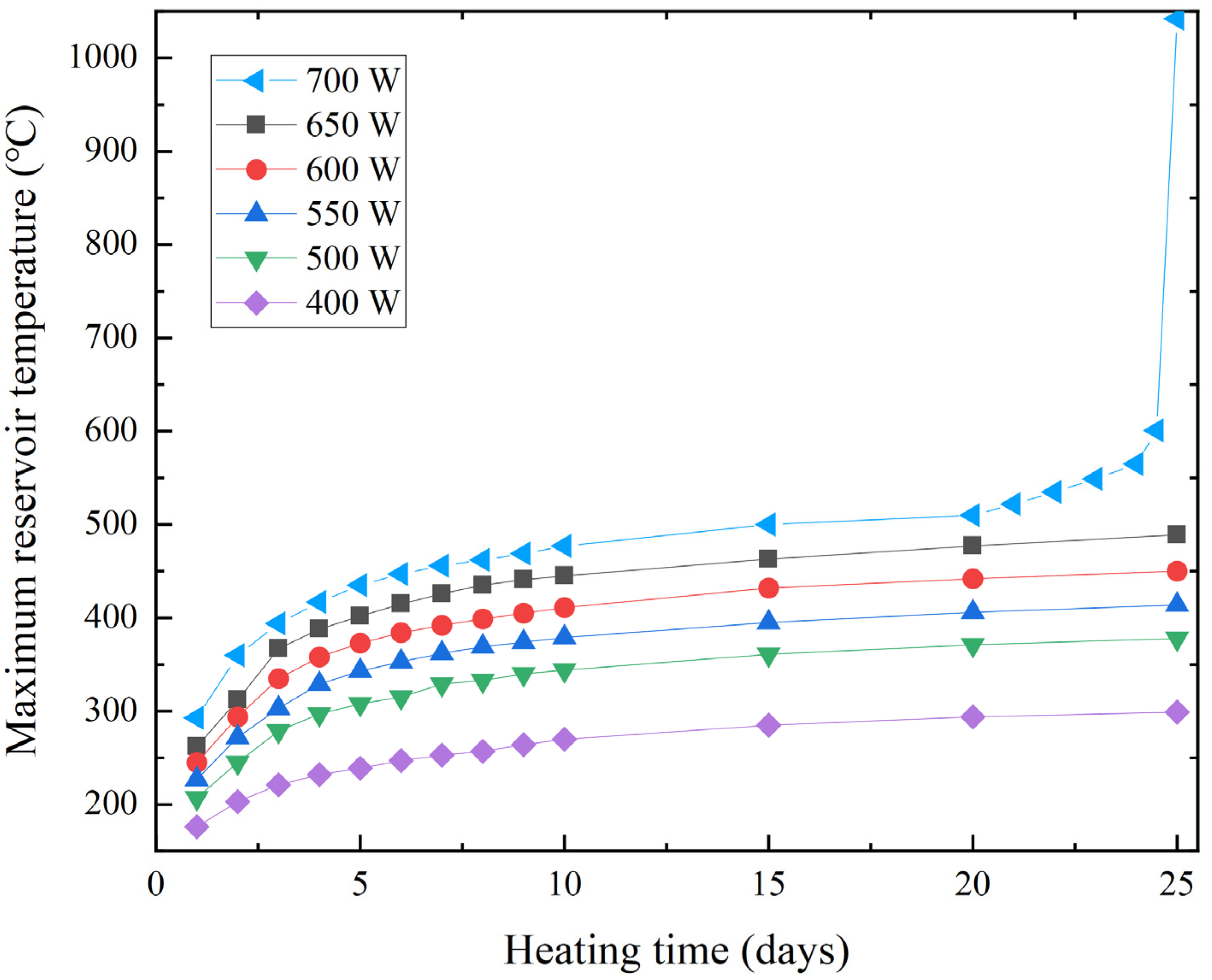
3.1. The Effect of Microwave Power

Many studies have proved that microwave power plays an essential role in influencing heating rate when irradiating material. Based on the coaxial port design, the port excites the microwave and the antenna emits it to the surrounding formation. Since the metal material of the wellbore may influence the propagation of microwaves, researchers found that an open-hole well or changing the material of the casing, such as polytetrafluoroethylene (PTFE), can overcome this problem [32]. Figure 5 shows the reservoir temperature distribution at different stages under 500 W of microwave heating. It is apparent that microwave power can enhance the region’s temperature near the heater in a very short time. In Figure 5a, the maximum reservoir temperature increases to 344 °C within 10 days under that microwave power. However, restricted by the microwave transmission distance, the remote region of the reservoir cannot be irradiated immediately, so thermal conduction is the primary heating mechanism for the remote region. Figure 6 shows the heating mechanism of the oil shale reservoir under microwave irradiation. In region 1, there is a high temperature region benefiting from the fast heating efficiency of microwave irradiation. In region 2, it is close to high-temperature region 1, and the increase in its corresponding temperature is due to thermal conduction. Therefore, thermal conductivity is a significant parameter for all heating methods, including electric heating, steam injection, and microwave heating. In other words, the heating mechanism of microwave is to provide a high-temperature region close to heating well with low energy consumption and fast heating efficiency. In this case, 500 W microwave power leads to the maximum reservoir temperature of oil shale as 431 °C at 1000 days.
In our previous experimental study [16], the heating rate increases with microwave heating power rising. The numerical calculations in the study captured the same phenomenon. As microwave heating is beneficial for increasing reservoir temperature before too long, Figure 7 shows the maximum reservoir temperature variation during 25 days of irradiation under different microwave power. When microwave power is 400 W, the temperature cannot reach the pyrolysis temperature of oil shale after 25 days. However, when microwave power is 700 W, the heating rate is too fast, especially when the maximum temperature accelerates rapidly over 600 °C; the maximum reservoir temperature of oil shale reaches 1000 °C at 24.5 days. This phenomenon demonstrates that the heat generated by the high output power cannot transfer to region 2 immediately as shown in Figure 6; therefore, the super-heat region is formed, which corresponds to region 1. Two aspects lead to this result. One reason is the dielectric properties of oil shale increase with the rising temperature, so that the abilities of oil shale that absorb electromagnetic energy and transfer it to heat are enhanced by high temperature. Moreover, the thermal conductivity of oil shale decreases as the temperature rises due to the decomposition of oil shale, which is responsible for the slower heat transfer rate. These two settings in the model make the excessive temperature form more easily. During the oil shale microwave retorting, uniformity in temperature distribution is a key point because partial high temperature significantly arouses secondary oil cracking and decreases oil production [33]. To avoid the excessive temperature by hot spots, adjusting microwave power is a good solution benefiting from the easy control of microwave power [34].

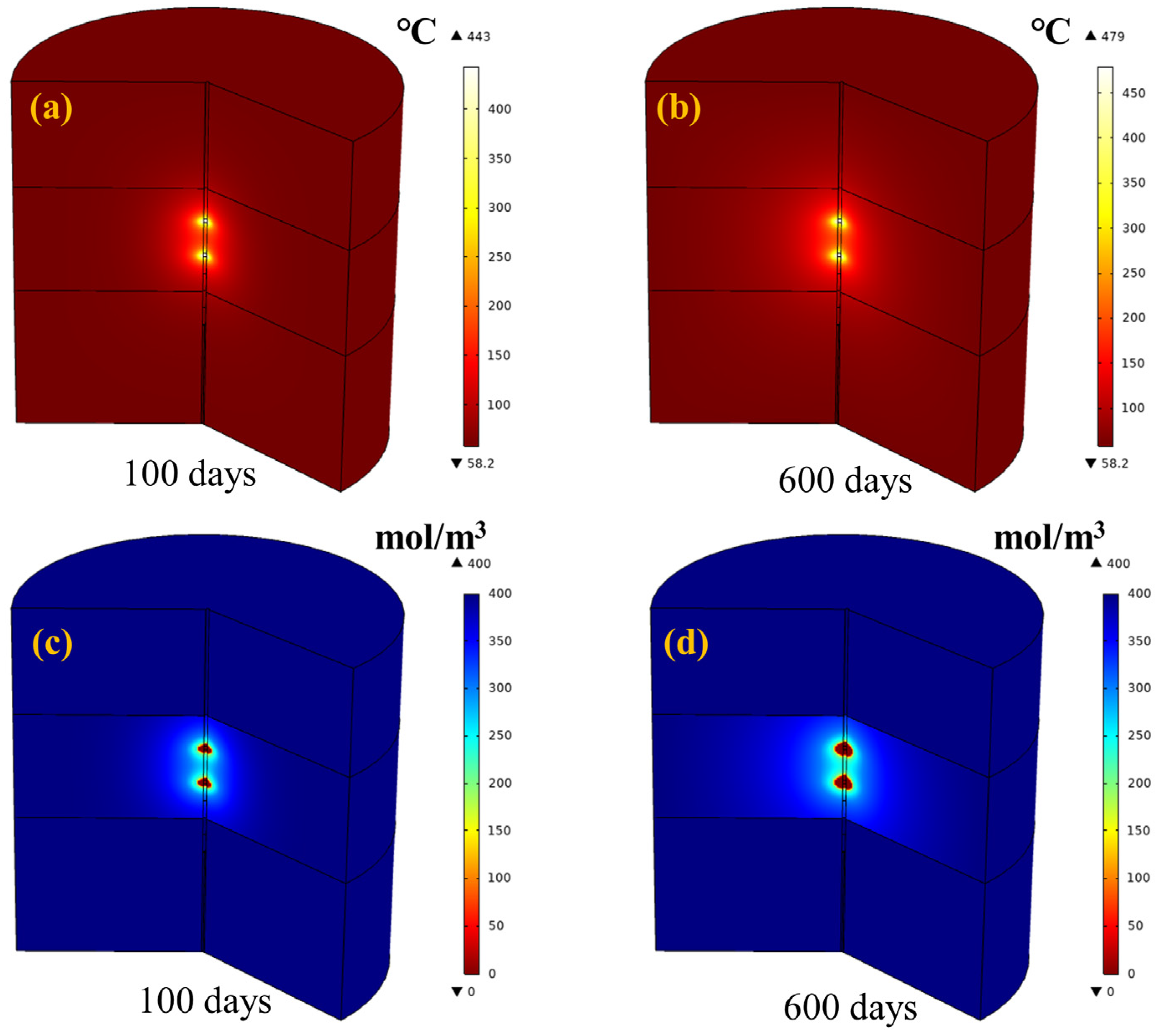
3.2. The Effect of Antenna Number

In Figure 2, the top and bottom layers are not oil shale, and the properties of these two layers are also different. It is needed to consider the location and number of antennas especially when the targeted layer is thin. Although some studies have already studied the in situ microwave heating technology in unconventional resources such as heavy oil [35] and coalbed methane [36] in terms of laboratory experiments and numerical analysis, there has been minimal attention paid to antenna design including antenna number and antenna position. Since the thermal conductivity of a reservoir restricts the heating efficiency of all thermal stimulation methods, increasing antenna number in the vertical well may be a good solution. Figure 8 shows the temperature distribution and kerogen distribution when two antennas irradiate the oil shale at 500 W in the case of the distance between two antennas being set to 0.9 m. The maximum temperature can reach 443 °C at 100 days. Compared with Figure 5b, two antennas help to increase the targeted reservoir temperature more efficiently. Under microwave irradiation, oil shale starts to decompose, and Figure 8c shows that the kerogen near the wellbore quickly converts to hydrocarbon products. Through thermal conduction, kerogen decomposition occurs in distal formation, as shown in Figure 8d.
Figure 9 shows the distribution of retorting products under microwave heating at 500 W with two antennas. The retorting products include not only heavy oil and light oil, which are mainly high-value products, but also methane and other nonhydrocarbon gases. In Figure 9a,b, heavy oil and light oil exhibit distributions similar to a ring. The concentration of light oil is higher than that of heavy oil. This phenomenon is due to the secondary cracking of oil products, as shown in Table 1. Although oil shale is retorted and hydrocarbon products are generated, high-value oil products also undergo thermal decomposition at high temperature. Since the top temperature region approximates the heating well, oil production is reduced by secondary cracking. As shown in Figure 9a, heavy oil converts into micromolecular species, including light oil, methane, and nonhydrocarbon gas. Moreover, light oil would also crack into gases with a smaller molecular weight. Therefore, the maximum concentration of heavy oil and light oil are 3.99 mol/m3 and 27.1 mol/m3 at 600 days, respectively. Conversely, secondary oil cracking generates more gases, including methane and other nonhydrocarbon gas; therefore, the maximum concentration of methane distributed near the wellbore is 4.5 mol/m3. In Figure 9d, the maximum nonhydrocarbon gas reaches 31.8 mol/m3, most of which are CO, CO2, and H2O. Hence, the secondary cracking of oil would be avoided as much as possible.

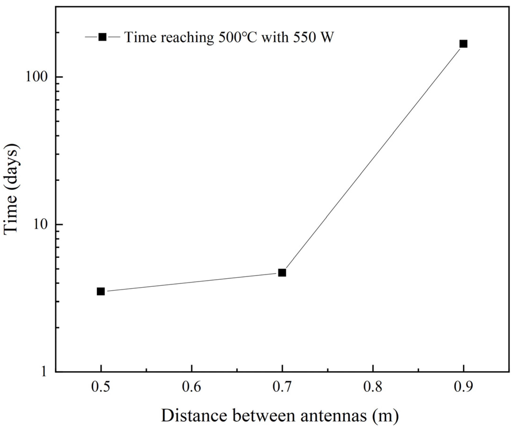
3.3. The Effect of Antenna Position

Although increasing the number of antennas benefits to higher heating rate and more irradiation area under microwave heating, the antenna position also dominates the microwave power and heating mode, especially when the oil shale layer is thin. If the distance between two antennas is too close, it is easier to form the excessive temperature region. During microwave irradiation, the early appearance of the super-heat region should be avoided. This necessitates the adjustment of microwave power.
Figure 10 shows the effect of distance between two antennas on time, reaching the maximum temperature of 500 °C irradiated with 550 W microwave. It can be seen that when the distance is 0.9 m, long continuous irradiation with 167 days results in a high temperature region with the maximum temperature of 500 °C. When reducing the distance between two antennas to 0.7 m, only 3 days of heating lead to the maximum temperature of 500 °C. Further reducing the distance to 0.5 m, less than 3 days heating reaches 500 °C. Although adjusting microwave power can slow down the appearance of excessive temperature regions, it is convenient to apply the continuous microwave with a constant power for a long time especially at the beginning of heating. Therefore, 0.9 m distance between two antennas is more proper in this model.
Apart from studying the time reaching excessive temperature region, the position of the oil shale formation layer should be another aspect to be considered. In other words, for the multiple thin layers of oil shale reservoir, the antennas should try to target the oil shale layer. Since the properties of oil shale also dominate the microwave heating parameters, the specific parameter optimization should be performed according to the specific oil shale reservoir.

4. Conclusions

A pseudo three-dimensional model herein, considering electromagnetics, temperature field, chemical reactions, and product distribution, was developed to analyze the retorting performance of oil shale reservoirs under microwave heating. There are three regions within the oil shale reservoir when subjected to microwave, including the microwave penetration region (region 1), heat transfer region (region 2), and no heating region (region 3). Although the temperature increases rapidly in region 1, excessive temperature would also be formed under high output power. In a typical case of a single antenna and the microwave power of 500 W, the maximum temperature of the oil shale reservoir rapidly increases to 344 °C within 10 days and 431 °C at 1000 days. For region 2, its temperature is dominated by heat transfer, so thermal conductivity is also crucial. In order to overcome the limitation of low thermal conductivity, the case of two antennas with the distance of 0.9 m and the microwave power of 500 W was researched. The result showed that the maximum temperature can reach 443 °C at 100 days irradiated by two antennas at 500 W and the kerogen near the wellbore quickly converts to hydrocarbon products. Under high temperature condition, not only kerogen but also oil products are under decomposition. Therefore, controlling the temperature of region 1 is highly important. Apart from adjusting the microwave power, the distance between two antennas should also be considered since excessive temperature is easily formed in region 1 when the distance is below 0.9 m. This study reveals the microwave retorting mechanism of oil shale reservoirs, and the results elucidate that microwave power and thermal conductivity are equally vital during the in situ retorting of oil shale. In this study, the feasibility of microwave heating in situ pyrolysis of oil shale for oil and hydrocarbon gas production was demonstrated from the perspective of numerical simulation to a certain extent, which explores a new way for the green and efficient development and utilization of oil shale. Based on the modeling process and solving method in this study, the development of the specific oil shale reservoir under microwave heating such as in Guangdong or Xinjiang province can be designed in the future.

Supplementary Materials

The following supporting information can be downloaded at: https://www.mdpi.com/article/10.3390/en15165788/s1, Governing Equations (Equations (S1)–(S20)). Figure S1. The relative permittivity and relative loss factor of oil shale at different temperature.

Author Contributions

Conceptualization, Z.Y., X.L. and J.Z. (Jingyi Zhu); methodology, H.W., J.S. and J.Z. (Jingyi Zhu); software, J.Z. (Jie Zhou); validation, H.W. and J.Z. (Jingyi Zhu); formal analysis, H.W. and J.Z. (Jingyi Zhu); investigation, H.W. and J.S.; resources, J.S. and X.M.; data curation, J.S. and J.Z. (Jingyi Zhu); writing—original draft preparation, H.W.; writing—review and editing, H.W. and J.Z. (Jingyi Zhu); visualization, H.W. and J.Z. (Jingyi Zhu); supervision, J.S. and X.M.; project administration, Z.Y. and J.Z. (Jingyi Zhu); funding acquisition, J.S., X.M. and L.Y. All authors have read and agreed to the published version of the manuscript.

Funding

The authors would like to thank the financial support from State Center for Research and Development of Oil Shale Exploitation (33550000-21-ZC0613-0132), China Postdoctoral Science Foundation (Grant Number: 2020M683361, Grant Number: 2021M700113) and Scientific Research Starting Project of SWPU (Grant Number: 2021QHZ038).

Institutional Review Board Statement

Not applicable.

Informed Consent Statement

Not applicable.

Data Availability Statement

Not applicable.

Acknowledgments

The authors would like to express our appreciation to Li Wei for supplying the computer resources for the numerical simulation calculations.

Conflicts of Interest

The authors declare no conflict of interest.

Nomenclature

EElectric field intensity (V/m)QcChemical reactions heat (W/m3)
BMagnetic flux density (Wb/m2)keffEffective thermal conductivity (W/(m·K))
HMagnetic field intensity (A/m)koThermal conductivity of matrix (W/(m·K))
DElectric flux density (A/m2)kfThermal conductivity of fluid (W/(m·K))
JCurrent density (A/m2)θpSolid volume fraction
ρecElectric charge density (C/m3)rjThe reaction rate (mol/(m3·s))
µrRelative permeabilitykfjForward rate constant (mol/(m3·s))
k0Wave numberciConcentration of component i (mol/m3)
σElectrical conductivity (S/m)vijStoichiometric coefficient
ωAngular frequency (rad/s)AjFrequency factor (1/s)
εrRelative permittivityEjActivation energy of reaction j (J/mol)
ε0Vacuum permittivity (8.854 × 10⁻¹² F/m)RgGas constant (8.314 J/(mol·K))
QeElectromagnetic losses (W/m3)εpPorosity
ε′Relative dielectric constantJiMass flux (mol/(m2·s))
ε″Relative dielectric loss factorRiMass source (mol/(m3·s))
CpHeat capacity (J/(kg·K))De,iEffective diffusion coefficient (m2/s)
TAbsolute temperature (K)DF,iSingle-phase coefficient (m2/s)
ρsDensity (kg/m3)τF,iTortuosity
qConductive heat flux (W/m²)µFluid’s dynamic viscosity (Pa·s)

References

  1. Liu, X.; Pan, H.; Guo, C.; Di, X.; Hu, H. Effect of Double Transition Metal Salt Catalyst on Fushun Oil Shale Pyrolysis. Scanning 2020, 2020, 6685299. [Google Scholar] [CrossRef] [PubMed]
  2. Li, D.; Pan, H.; Di, X.; Liu, X.; Hu, H. Progress in Catalytic Pyrolysis of Oil Shale. Scanning 2021, 2021, 6759176. [Google Scholar] [CrossRef] [PubMed]
  3. Wang, D.; Liu, Y.; Zhang, T.; Christopher, D.H.; Bature, N.S.; Fan, T.; Guo, H. Structural and quantitative evolution of organic matters in oil shale during two different retorting processes. AIChE J. 2021, 67, e17278. [Google Scholar] [CrossRef]
  4. Wang, L.; Yang, D.; Kang, Z. Evolution of permeability and mesostructure of oil shale exposed to high-temperature water vapor. Fuel 2021, 290, 119786. [Google Scholar] [CrossRef]
  5. Kang, Z.; Zhao, Y.; Yang, D. Review of oil shale in-situ conversion technology. Appl. Energy 2020, 269, 115121. [Google Scholar] [CrossRef]
  6. Yang, L.; Li, P. Evolution of the Oil Shale Permeability under Real-Time High-Temperature Triaxial Stress in the Jimusar Area, Xinjiang. Geofluids 2021, 2021, 7068973. [Google Scholar] [CrossRef]
  7. Xu, S.; Sun, Y.; Lü, X.; Yang, Q.; Li, Q.; Wang, Z.; Guo, M. Effects of composition and pore evolution on thermophysical properties of Huadian oil shale in retorting and oxidizing pyrolysis. Fuel 2021, 305, 121565. [Google Scholar] [CrossRef]
  8. Zhu, J.; Yi, L.; Yang, Z.; Li, X. Numerical simulation on the in situ upgrading of oil shale reservoir under microwave heating. Fuel 2021, 287, 119553. [Google Scholar] [CrossRef]
  9. Yang, D.; Wang, L.; Zhao, Y.; Kang, Z. Investigating pilot test of oil shale pyrolysis and oil and gas upgrading by water vapor injection. J. Pet. Sci. Eng. 2021, 196, 108101. [Google Scholar] [CrossRef]
  10. Zhao, J.; Kang, Z. Permeability of Oil Shale Under In Situ Conditions: Fushun Oil Shale (China) Experimental Case Study. Nat. Resour. Res. 2021, 30, 753–763. [Google Scholar] [CrossRef]
  11. Kang, Z.; Zhao, Y.; Yang, D.; Tian, L.; Li, X. A pilot investigation of pyrolysis from oil and gas extraction from oil shale by in-situ superheated steam injection. J. Pet. Sci. Eng. 2020, 186, 106785. [Google Scholar] [CrossRef]
  12. Zhao, S.; Lü, X.; Li, Q.; Sun, Y. Thermal-fluid coupling analysis of oil shale pyrolysis and displacement by heat-carrying supercritical carbon dioxide. Chem. Eng. J. 2020, 394, 125037. [Google Scholar] [CrossRef]
  13. Wang, Z.; Lü, X.; Li, Q.; Sun, Y.; Wang, Y.; Deng, S.; Guo, W. Downhole electric heater with high heating efficiency for oil shale exploitation based on a double-shell structure. Energy 2020, 211, 118539. [Google Scholar] [CrossRef]
  14. Kibodeaux, K.R. Evolution of Porosity Permeability, and Fluid Saturations During Thermal Conversion of Oil Shale. In Proceedings of the SPE Annual Technical Conference and Exhibition, Amsterdam, The Netherlands, 27–29 October 2014. [Google Scholar] [CrossRef]
  15. Hascakir, B.; Akin, S. Recovery of Turkish Oil Shales by Electromagnetic Heating and Determination of the Dielectric Properties of Oil Shales by an Analytical Method. Energy Fuels 2010, 24, 503–509. [Google Scholar] [CrossRef]
  16. Yang, Z.; Zhu, J.; Li, X.; Luo, D.; Qi, S.; Jia, M. Experimental Investigation of the Transformation of Oil Shale with Fracturing Fluids under Microwave Heating in the Presence of Nanoparticles. Energy Fuels 2017, 31, 10348–10357. [Google Scholar] [CrossRef]
  17. El harfi, K.; Mokhlisse, A.; Chanâa, M.B.; Outzourhit, A. Pyrolysis of the Moroccan (Tarfaya) oil shales under microwave irradiation. Fuel 2000, 79, 733–742. [Google Scholar] [CrossRef]
  18. Neto, A.; Thomas, S.; Bond, G.; Thibault-Starzyk, F.; Ribeiro, F.; Henriques, C. The Oil Shale Transformation in the Presence of an Acidic BEA Zeolite under Microwave Irradiation. Energy Fuels 2014, 28, 2365–2377. [Google Scholar] [CrossRef] [Green Version]
  19. He, L.; Ma, Y.; Yue, C.; Li, S.; Tang, X. The heating performance and kinetic behaviour of oil shale during microwave pyrolysis. Energy 2022, 244, 123021. [Google Scholar] [CrossRef]
  20. Lee, K.; Moridis, G.J.; Ehlig-Economides, C.A. A Comprehensive Simulation Model of Kerogen Pyrolysis for the In-situ Upgrading of Oil Shales. SPE J. 2016, 21, 1612–1630. [Google Scholar] [CrossRef] [Green Version]
  21. Brandt, A.R. Converting Oil Shale to Liquid Fuels: Energy Inputs and Greenhouse Gas Emissions of the Shell in Situ Conversion Process. Environ. Sci. Technol. 2008, 42, 7489–7495. [Google Scholar] [CrossRef]
  22. Symington, W.A.; Olgaard, D.L.; Otten, G.A.; Phillips, T.C.; Thomas, M.M.; Yeakel, J.D. ExxonMobil’s Electrofrac Process for In Situ Oil Shale Conversion. In Proceedings of the 26th Oil Shale Symposium, Golden, CO, USA, 16–18 October 2006; Available online: https://www.searchanddiscovery.com/pdfz/documents/2008/08131symington/ndx_symington.pdf.html (accessed on 7 July 2022).
  23. Peng, M.; Li, W.-q.; Tan, H.-f.; Lin, L. Simulation Study on Microwave Heating Mechanism of Shale Oil in Situ. In Proceedings of the International Petroleum and Petrochemical Technology Conference 2020, Shanghai, China, 26–28 August 2020; Springer: Singapore, 2021; pp. 439–455. [Google Scholar] [CrossRef]
  24. Song, X.; Zhang, C.; Shi, Y.; Li, G. Production performance of oil shale in-situ conversion with multilateral wells. Energy 2019, 189, 116145. [Google Scholar] [CrossRef]
  25. Xu, T.; Yuan, Y.; Heap, M.J.; Zhou, G.-L.; Perera, M.S.A.; Ranjith, P.G. Microwave-assisted damage and fracturing of hard rocks and its implications for effective mineral resources recovery. Miner. Eng. 2021, 160, 106663. [Google Scholar] [CrossRef]
  26. Youtsos, M.S.K.; Mastorakos, E.; Cant, R.S. Numerical simulation of thermal and reaction fronts for oil shale upgrading. Chem. Eng. Sci. 2013, 94, 200–213. [Google Scholar] [CrossRef]
  27. Al-Harahsheh, M.; Kingman, S.; Saeid, A.; Robinson, J.; Dimitrakis, G.; Alnawafleh, H. Dielectric properties of Jordanian oil shales. Fuel Processing Technol. 2009, 90, 1259–1264. [Google Scholar] [CrossRef]
  28. Fianu, J.; Gholinezhad, J.; Hassan, M. Thermal simulation of shale gas recovery involving the use of microwave heating. J. Pet. Sci. Eng. 2020, 186, 106768. [Google Scholar] [CrossRef]
  29. Liu, J.; Wang, J.; Leung, C.; Gao, F. A Fully Coupled Numerical Model for Microwave Heating Enhanced Shale Gas Recovery. Energies 2018, 11, 1608. [Google Scholar] [CrossRef] [Green Version]
  30. Wang, Z.; Tang, X.; Yue, G.; Kang, B.; Xie, C.; Li, X. Physical simulation of temperature influence on methane sorption and kinetics in coal: Benefits of temperature under 273.15K. Fuel 2015, 158, 207–216. [Google Scholar] [CrossRef]
  31. Zhou, J.; Yang, X.; Chu, Y.; Li, X.; Yuan, J. A novel algorithm approach for rapid simulated microwave heating of food moving on a conveyor belt. J. Food Eng. 2020, 282, 110029. [Google Scholar] [CrossRef]
  32. Bientinesi, M.; Petarca, L.; Cerutti, A.; Bandinelli, M.; De Simoni, M.; Manotti, M.; Maddinelli, G. A radiofrequency/microwave heating method for thermal heavy oil recovery based on a novel tight-shell conceptual design. J. Pet. Sci. Eng. 2013, 107, 18–30. [Google Scholar] [CrossRef]
  33. Wang, Z.; Gao, D.; Diao, B.; Tan, L.; Zhang, W.; Liu, K. Comparative performance of electric heater vs. RF heating for heavy oil recovery. Appl. Therm. Eng. 2019, 160, 114105. [Google Scholar] [CrossRef]
  34. Eskandari, S.; Jalalalhosseini, S.M.; Mortezazadeh, E. Microwave Heating as an Enhanced Oil Recovery Method—Potentials and Effective Parameters. Energy Sources Part A Recovery Util. Environ. Eff. 2015, 37, 742–749. [Google Scholar] [CrossRef]
  35. Fia, A.Z.; Amorim, J. Heating of biomass in microwave household oven—A numerical study. Energy 2021, 218, 119472. [Google Scholar] [CrossRef]
  36. Lan, W.; Wang, H.; Liu, Q.; Zhang, X.; Chen, J.; Li, Z.; Feng, K.; Chen, S. Investigation on the microwave heating technology for coalbed methane recovery. Energy 2021, 237, 121450. [Google Scholar] [CrossRef]
Figure 1. Mathematical equations and their corresponding relationships.
Energies 15 05788 g001
Figure 2. Pseudo three-dimensional model for the oil shale in situ retorting under microwave irradiation.
Energies 15 05788 g002
Figure 3. Calculation process for oil shale retorting under microwave heating.
Energies 15 05788 g003
Figure 4. Grid-independent validation of the simulation.
Energies 15 05788 g004
Figure 5. Reservoir temperature distribution of oil shale formation under microwave irradiation at 500 W over time: (a) 10 days, (b) 100 days, and (c) 1000 days.
Energies 15 05788 g005
Figure 6. Heating mechanism of oil shale layer subjected to microwave heating.
Energies 15 05788 g006
Figure 7. The maximum reservoir temperature of oil shale under different microwave power levels for 25 days.
Energies 15 05788 g007
Figure 8. The effect of antennas number on the temperature distribution and kerogen decomposition: (a) reservoir temperature at 100 days, (b) reservoir temperature at 600 days, (c) kerogen concentration at 100 days, and (d) kerogen concentration at 600 days.
Energies 15 05788 g008
Figure 9. The distribution of retorting products at 600 days: (a) heavy oil, (b) light oil, (c) methane, and (d) nonhydrocarbon gas.
Energies 15 05788 g009
Figure 10. The effect of the distance between two antennas on time reaching 500 °C at 550 W under microwave heating.
Energies 15 05788 g010
Table 1. Kinetic data for chemical reactions [26].
Decomposition ReactionFrequency Factor
(1/s)
Activation Energy (kJ/mol)Enthalpy
(J/mol)
Kerogen (oil shale) → 0.279 Heavy Oil + 0.143 Light Oil + 0.018 Gas + 0.005 Methane + 0.555 Coke13.0 × 1013225.9−335,000
Heavy Oil → 0.037 Light Oil + 0.156 Gas + 0.03 Methane + 0.441 Coke25.0 × 1011225.9−46,500
Light Oil → 0.595 Gas + 0.115 Methane + 0.29 Coke31.0 × 1013213.4−46,500
Coke1 → 0.031 Gas + 0.033 Methane + 0.936 Coke21.0 × 1013225.9−46,500
Coke2 → 0.003 Gas + 0.033 Methane + 0.964 Coke35.0 × 1011225.9−46,500
Table 2. Initial conditions and parameters of the proposed model.
ParameterSymbolValueSource
Initial temperatureT0323.15 KGiven
Initial pressureP08 MPaGiven
Well diameterdwell0.1 mGiven
Microwave frequencyf2.45 GHzGiven
Microwave powerP400 WGiven
Kerogen concentrationcker400 mol/m3Ref. [26]
Gas diffusion coefficientDgas1 × 10−9 m2/sRef. [30]
Methane diffusion coefficientDch2 × 10−9 m2/sRef. [30]
Publisher’s Note: MDPI stays neutral with regard to jurisdictional claims in published maps and institutional affiliations.

